CN101512018B - Chip and cartridge design configuration for performing micro-fluidic assays - Google Patents
Chip and cartridge design configuration for performing micro-fluidic assays Download PDFInfo
- Publication number
- CN101512018B CN101512018B CN2007800331479A CN200780033147A CN101512018B CN 101512018 B CN101512018 B CN 101512018B CN 2007800331479 A CN2007800331479 A CN 2007800331479A CN 200780033147 A CN200780033147 A CN 200780033147A CN 101512018 B CN101512018 B CN 101512018B
- Authority
- CN
- China
- Prior art keywords
- micro
- fluidic chip
- test case
- microchannel
- assembly
- Prior art date
- Legal status (The legal status is an assumption and is not a legal conclusion. Google has not performed a legal analysis and makes no representation as to the accuracy of the status listed.)
- Expired - Fee Related
Links
Images


Classifications
-
- B—PERFORMING OPERATIONS; TRANSPORTING
- B01—PHYSICAL OR CHEMICAL PROCESSES OR APPARATUS IN GENERAL
- B01L—CHEMICAL OR PHYSICAL LABORATORY APPARATUS FOR GENERAL USE
- B01L3/00—Containers or dishes for laboratory use, e.g. laboratory glassware; Droppers
- B01L3/50—Containers for the purpose of retaining a material to be analysed, e.g. test tubes
- B01L3/502—Containers for the purpose of retaining a material to be analysed, e.g. test tubes with fluid transport, e.g. in multi-compartment structures
- B01L3/5027—Containers for the purpose of retaining a material to be analysed, e.g. test tubes with fluid transport, e.g. in multi-compartment structures by integrated microfluidic structures, i.e. dimensions of channels and chambers are such that surface tension forces are important, e.g. lab-on-a-chip
- B01L3/502715—Containers for the purpose of retaining a material to be analysed, e.g. test tubes with fluid transport, e.g. in multi-compartment structures by integrated microfluidic structures, i.e. dimensions of channels and chambers are such that surface tension forces are important, e.g. lab-on-a-chip characterised by interfacing components, e.g. fluidic, electrical, optical or mechanical interfaces
-
- B—PERFORMING OPERATIONS; TRANSPORTING
- B01—PHYSICAL OR CHEMICAL PROCESSES OR APPARATUS IN GENERAL
- B01F—MIXING, e.g. DISSOLVING, EMULSIFYING OR DISPERSING
- B01F25/00—Flow mixers; Mixers for falling materials, e.g. solid particles
- B01F25/40—Static mixers
- B01F25/42—Static mixers in which the mixing is affected by moving the components jointly in changing directions, e.g. in tubes provided with baffles or obstructions
- B01F25/43—Mixing tubes, e.g. wherein the material is moved in a radial or partly reversed direction
- B01F25/433—Mixing tubes wherein the shape of the tube influences the mixing, e.g. mixing tubes with varying cross-section or provided with inwardly extending profiles
- B01F25/4331—Mixers with bended, curved, coiled, wounded mixing tubes or comprising elements for bending the flow
-
- B—PERFORMING OPERATIONS; TRANSPORTING
- B01—PHYSICAL OR CHEMICAL PROCESSES OR APPARATUS IN GENERAL
- B01F—MIXING, e.g. DISSOLVING, EMULSIFYING OR DISPERSING
- B01F33/00—Other mixers; Mixing plants; Combinations of mixers
- B01F33/30—Micromixers
-
- B—PERFORMING OPERATIONS; TRANSPORTING
- B01—PHYSICAL OR CHEMICAL PROCESSES OR APPARATUS IN GENERAL
- B01L—CHEMICAL OR PHYSICAL LABORATORY APPARATUS FOR GENERAL USE
- B01L7/00—Heating or cooling apparatus; Heat insulating devices
- B01L7/52—Heating or cooling apparatus; Heat insulating devices with provision for submitting samples to a predetermined sequence of different temperatures, e.g. for treating nucleic acid samples
-
- B—PERFORMING OPERATIONS; TRANSPORTING
- B01—PHYSICAL OR CHEMICAL PROCESSES OR APPARATUS IN GENERAL
- B01F—MIXING, e.g. DISSOLVING, EMULSIFYING OR DISPERSING
- B01F25/00—Flow mixers; Mixers for falling materials, e.g. solid particles
- B01F25/40—Static mixers
- B01F25/42—Static mixers in which the mixing is affected by moving the components jointly in changing directions, e.g. in tubes provided with baffles or obstructions
-
- B—PERFORMING OPERATIONS; TRANSPORTING
- B01—PHYSICAL OR CHEMICAL PROCESSES OR APPARATUS IN GENERAL
- B01L—CHEMICAL OR PHYSICAL LABORATORY APPARATUS FOR GENERAL USE
- B01L2200/00—Solutions for specific problems relating to chemical or physical laboratory apparatus
- B01L2200/02—Adapting objects or devices to another
- B01L2200/026—Fluid interfacing between devices or objects, e.g. connectors, inlet details
- B01L2200/027—Fluid interfacing between devices or objects, e.g. connectors, inlet details for microfluidic devices
-
- B—PERFORMING OPERATIONS; TRANSPORTING
- B01—PHYSICAL OR CHEMICAL PROCESSES OR APPARATUS IN GENERAL
- B01L—CHEMICAL OR PHYSICAL LABORATORY APPARATUS FOR GENERAL USE
- B01L2200/00—Solutions for specific problems relating to chemical or physical laboratory apparatus
- B01L2200/04—Exchange or ejection of cartridges, containers or reservoirs
-
- B—PERFORMING OPERATIONS; TRANSPORTING
- B01—PHYSICAL OR CHEMICAL PROCESSES OR APPARATUS IN GENERAL
- B01L—CHEMICAL OR PHYSICAL LABORATORY APPARATUS FOR GENERAL USE
- B01L2200/00—Solutions for specific problems relating to chemical or physical laboratory apparatus
- B01L2200/06—Fluid handling related problems
- B01L2200/0647—Handling flowable solids, e.g. microscopic beads, cells, particles
- B01L2200/0668—Trapping microscopic beads
-
- B—PERFORMING OPERATIONS; TRANSPORTING
- B01—PHYSICAL OR CHEMICAL PROCESSES OR APPARATUS IN GENERAL
- B01L—CHEMICAL OR PHYSICAL LABORATORY APPARATUS FOR GENERAL USE
- B01L2200/00—Solutions for specific problems relating to chemical or physical laboratory apparatus
- B01L2200/16—Reagents, handling or storing thereof
-
- B—PERFORMING OPERATIONS; TRANSPORTING
- B01—PHYSICAL OR CHEMICAL PROCESSES OR APPARATUS IN GENERAL
- B01L—CHEMICAL OR PHYSICAL LABORATORY APPARATUS FOR GENERAL USE
- B01L2300/00—Additional constructional details
- B01L2300/08—Geometry, shape and general structure
- B01L2300/0809—Geometry, shape and general structure rectangular shaped
- B01L2300/0829—Multi-well plates; Microtitration plates
-
- B—PERFORMING OPERATIONS; TRANSPORTING
- B01—PHYSICAL OR CHEMICAL PROCESSES OR APPARATUS IN GENERAL
- B01L—CHEMICAL OR PHYSICAL LABORATORY APPARATUS FOR GENERAL USE
- B01L2300/00—Additional constructional details
- B01L2300/08—Geometry, shape and general structure
- B01L2300/0861—Configuration of multiple channels and/or chambers in a single devices
- B01L2300/0867—Multiple inlets and one sample wells, e.g. mixing, dilution
-
- B—PERFORMING OPERATIONS; TRANSPORTING
- B01—PHYSICAL OR CHEMICAL PROCESSES OR APPARATUS IN GENERAL
- B01L—CHEMICAL OR PHYSICAL LABORATORY APPARATUS FOR GENERAL USE
- B01L2300/00—Additional constructional details
- B01L2300/08—Geometry, shape and general structure
- B01L2300/0861—Configuration of multiple channels and/or chambers in a single devices
- B01L2300/087—Multiple sequential chambers
-
- B—PERFORMING OPERATIONS; TRANSPORTING
- B01—PHYSICAL OR CHEMICAL PROCESSES OR APPARATUS IN GENERAL
- B01L—CHEMICAL OR PHYSICAL LABORATORY APPARATUS FOR GENERAL USE
- B01L2400/00—Moving or stopping fluids
- B01L2400/04—Moving fluids with specific forces or mechanical means
- B01L2400/0475—Moving fluids with specific forces or mechanical means specific mechanical means and fluid pressure
- B01L2400/0487—Moving fluids with specific forces or mechanical means specific mechanical means and fluid pressure fluid pressure, pneumatics
- B01L2400/049—Moving fluids with specific forces or mechanical means specific mechanical means and fluid pressure fluid pressure, pneumatics vacuum
Abstract
An assembly for performing micro-fluidic assays includes a micro-fluidic chip with access ports and micro-channels in communication with the access ports and a fluid cartridge having internal, fluid-containable chambers and a nozzle associated with each internal chamber that is configured to be coupled with an access port. Reaction fluids, such as sample material, buffer, and/or reagent, contained within the cartridge are dispensed from the cartridge into the access ports and micro-channels of the micro-fluidic chip. Embodiments of the invention include a cartridge which includes a waste compartment for receiving used DNA and other reaction fluids from the micro-channel at the conclusion of the assay.
Description
The cross reference of related application
The application requires the U.S. Provisional Application No.60/824 of submission on September 6th, 2006, and 654 right of priority is incorporated herein by reference at this.
Technical field
The present invention relates to a kind of container be used to carrying out the microfluid chemical examination, more particularly, the present invention relates to a kind of test case (cartridge) be used to holding sampling substance and optional laboratory reagent, buffer reagent and waste material, described test case can be connected with the micro-fluidic chip with microchannel (chip), in micro-fluidic chip, the sampling substance that transports in test case is carried out chemical examination such as real-time polymerase chain reaction.
Background technology
Detection of nucleic acids is the breeding of medical science, medical jurisprudence, commercial run, farm crop and animal and the core in many other fields.Ordinary skill for the investigating on the spot of medical diagnosis on disease and prediction, marker assisted selection, crime scene feature, industrial organic fecundity and many other techniques to the detectivity of disease situation (such as cancer), infectivity organism (such as acquired immune deficiency syndrome (AIDS)), genetic pedigree, genetic marker etc.The concern that the nucleic acid globality is measured may be relevant to the pathology of transmissible disease or cancer.Be some or all nucleotide sequences of multiple copies for detection of one of strong and the most basic technology of small quantities of nucleic acids, then analyze the product that amplifies.Polymerase chain reaction (" PCR ") may be the most well-known technology in a large amount of different amplifying techniques.
PCR is a kind of the strongest technology for amplifying short section of DNA.Utilize PCR, people can begin to produce fast DNA replication dna product up to a million from single template DNA molecule.PCR comprises the temperature cycle of three phases: the DNA sex change is strand, base fluid (primer) is annealed to the denatured strand temperature and by heat-resisting archaeal dna polymerase enzyme element, base fluid is extended.Repeat this circulation make have enough for detection of with the replica of analyzing.In principle, each circulation of PCR can make the quantity of replica double.In fact, the rear multiplication factor that obtains of each circulation is always less than 2.And, along with proceeding of PCR circulation, when required reactant concn reduces, finally stop amplifying the formation of PCR product.About total detailed content of PCR referring to Sambrook and Russell, Molecular Cloning--ALaboratory Manual (3rd Ed.), Vols.1-3, Cold Spring HarborLaboratory, Cold Spring Harbor, N.Y. (2000); Current Protocols inMolecular Biology, F.M.Ausubel et al., eds., Current Protocols, ajoint venture between Greene Publishing Associates, Inc.and JohnWiley ﹠amp; Sons, Inc., (supplemented through 2005) and PCR ProtocolsA Guide to Methods and Applications, M.A.Innis et al., eds., AcademicPress Inc.San Diego, Calif. (1990).
PCR in real time relates to one group of developing technology, and wherein a kind of technology is along with reaction process (normally each PCR circulation is measured once) is measured the formation of amplifying the DNA product.The starting point concentration that the accumulation of long-term monitoring product allows people's assaying reaction efficient and estimates the DNA profiling molecule.About total detailed content of PCR referring to Real-Time PCR:An EssentialGuide, K.Edwards et al., eds., Horizon Bioscience, Norwich, U.K. (2004).
There is the real-time detection chemistries of some differences to be used to indicate the existence of amplifying DNA.These great majority that detect in chemistry depend on fluorescent flag, and this fluorescent flag changes character according to the result that PCR processes.In these detection chemistries with good grounds coupling to double-stranded DNA increase fluorescent effect DNA coupling dyestuff (such as
 Green).Other detection chemistries utilizes the Foerster resonance energy to shift (FRET), and according to Foerster resonance energy transfer phenomena, the fluorescent effect of dyestuff greatly depends on it near the degree of another photoabsorption part or quenching agent.These dyestuffs and quenching agent are attached on the probe or base fluid of DNA sequence dna special use usually.Hydrolysis probes or conformation probes are arranged in the detection chemistries based on FRET.Hydrolysis probes (such as
Dark pin) use polymerase enzyme that reporter dye molecules and the quenching agent dye molecule that is attached on nucleotide probe are separated.Conformation probes (such as molecular beacon) utilization is attached to the dyestuff on oligonucleotide, and its fluorescent radiation basis changes with the conformational change of the oligonucleotide of target dna hybridization.
Green).Other detection chemistries utilizes the Foerster resonance energy to shift (FRET), and according to Foerster resonance energy transfer phenomena, the fluorescent effect of dyestuff greatly depends on it near the degree of another photoabsorption part or quenching agent.These dyestuffs and quenching agent are attached on the probe or base fluid of DNA sequence dna special use usually.Hydrolysis probes or conformation probes are arranged in the detection chemistries based on FRET.Hydrolysis probes (such as
Dark pin) use polymerase enzyme that reporter dye molecules and the quenching agent dye molecule that is attached on nucleotide probe are separated.Conformation probes (such as molecular beacon) utilization is attached to the dyestuff on oligonucleotide, and its fluorescent radiation basis changes with the conformational change of the oligonucleotide of target dna hybridization.
Commonly assigned, co-pending, name is called the U. S. application No.11/505 of " PCR in real time in the microchannel ", 358 have described a kind ofly for flowing through microchannel and carry out the method for PCR by the drop of non-reacting fluid (such as the buffer agent solution of the usually said flow maker) discrete droplets of coming separated from one another, are incorporated herein its disclosure with for referencial use.
Cicada is for the device that carries out in the microchannel such as the online chemical examination of PCR for prior art, and described device comprises the micro-fluidic chip that is formed at one or more microchannel in the chemical examination sheet.These chemical examination sheets utilize sample sipper tube and are positioned at the chemical examination uppermost open port of sheet (openport) and receive reagent and sampling substance (for example DNA) and reagent and sampling substance (for example DNA) are transported to the microchannel of chemically examining sheet.Chemical examination sheet platform design is used at the open port place's reception reagent (usually being distributed by pipette) that is positioned at chemical examination sheet top, reagent flows into the microchannel from open port usually under the impact of vacuum, described vacuum is applied to the opposed end place of each microchannel.The DNA sampling is fed to the microchannel from microwell plate via suction pipe, and this suction pipe reaches under the chemical examination sheet and because the vacuum that imposes on the microchannel is aspirated sampling substance by this suction pipe from the hole.
Crossed contamination between contaminated-existing sampling that this open design is easy to and chemical examination has again the experimenter's who is exposed to potential infectivity medicament pollution.Thereby, a kind of improvement container be used to carrying out the microfluid chemical examination need to be arranged.
Summary of the invention
The present invention relates to use test case docking micro-fluidic chip, described test case holds or is suitable for holding reacting fluid or byproduct, and described micro-fluidic chip provides for DNA analysis test and other chemical examinations of carrying out handiness and the easiness used in micro-fluidic chip.Test case holds the DNA sampling and can comprise buffer reagent and/or one or more reagent that will use in chemical examination, this test case also can comprise the waste material accommodating chamber that can form " closure " microfluid system, make DNA sampling and other reaction product turn back to same sampling accommodation box by this " closure " microfluid system, thereby eliminated the needs of independent management harmful organism waste material.Patient's sampling is introduced microfluidic channel (or microchannel) via test case and will chemically examine application specific probe/base fluid and introduce each sampling drop and guarantee keeping advantage online, the consecutive PCR assay process not exist sampling between the patient-sampling to carry secretly simultaneously.
Aspect of the present invention is embodied in a kind of assembly for carrying out the microfluid chemical examination, and this assembly comprises micro-fluidic chip and fluid test case.Micro-fluidic chip has end face and bottom surface and comprises one or more ingress ports and at least one microchannel that is formed on end face, and this at least one microchannel extends through at least a portion micro-fluidic chip from the ingress port that is associated.Each ingress port is communicated with the microchannel that is associated, make the fluid that is assigned to ingress port flow in the microchannel that is associated, the fluid tip that the fluid test case has one or more inner rooms for containing fluid and is associated with each inner room, described nozzle are used for from the chamber distributing fluids that is associated or fluid are sent to the inner room that is associated.Each fluid tip is configured to connect with the ingress port of micro-fluidic chip, thereby fluid is assigned to the ingress port that connects with nozzle from the inner room that is associated, and perhaps fluid is sent to the inner room that is associated from the ingress port with the nozzle connection.
In other embodiments, provide a kind of test case device that is configured to micro-fluidic chip, wherein the test case device comprises conveying chamber and reclaims the chamber.Conveying chamber is communicated with the delivery port fluid and is configured to hold reacting fluid.Delivery port is configured to and micro-fluidic chip.Reclaiming the chamber is communicated with the recovery port fluid and is configured to receive waste material from micro-fluidic chip.Recovery port is configured to and micro-fluidic chip.
Still in other embodiments, a kind of test case device that is configured to micro-fluidic chip is provided, described test case device comprise the reagent conveying chamber that is connected with the reagent delivery port, the buffer reagent conveying chamber that is connected with the buffer reagent delivery port, with sampling delivery port the sampling conveying chamber that is connected and the waste recovery chamber that is connected with the waste recovery port, wherein reagent delivery port, buffer reagent delivery port, the delivery port of sampling and waste recovery port all are configured to and micro-fluidic chip.In this embodiment, micro-fluidic chip comprises one or more microchannel, and one or more in reagent, buffer reagent and/or sampling are from flow through this one or more microchannel and enter described waste recovery chamber of reagent conveying chamber, buffer reagent conveying chamber and/or sampling conveying chamber.
Other aspects of the present invention comprise the mutual relationship of working method, function and the element of structure, in the situation that reference accompanying drawing, the following explanation of consideration and appended claim, to become more apparent, all these contents have formed a part of the present invention, and wherein identical Reference numeral represents corresponding parts in each width figure.
Description of drawings
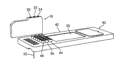
Fig. 1 a is the skeleton view that embodies an embodiment of the micro-fluidic chip of aspect of the present invention and test case, and wherein test case is shown as with micro-fluidic chip and separates;
Fig. 1 b is the skeleton view of the micro-fluidic chip shown in Fig. 1 a and test case, and wherein test case is shown as with micro-fluidic chip and connects;
Fig. 2 a is the skeleton view of the assembly that is made of micro-fluidic chip and test case shown in Fig. 1 b, and wherein assembly operationally is positioned at the microwell plate top;
Fig. 2 b is the side-view of the assembly that is made of micro-fluidic chip and test case shown in Fig. 1 b, and wherein assembly operationally is positioned at the microwell plate top;
Fig. 3 is the microchannel of micro-fluidic chip and the schematic diagram of suction pipe, and wherein suction pipe engages with the hole of microwell plate;
Fig. 4 is the schematic diagram that carries out being contained in the process of microfluid chemical examination the reacting fluid in the microchannel in the microchannel;
Fig. 5 is using the assembly that is made of micro-fluidic chip and test case that operationally is arranged together with the microwell plate shown in Fig. 2 a and 2b to carry out the schema of the step that process is carried out of microfluid chemical examination for explanation;
Fig. 6 is the skeleton view that embodies an alternate embodiment of the micro-fluidic chip of aspect of the present invention and test case, and wherein test case is shown as with micro-fluidic chip and connects;
Fig. 7 is the schematic diagram of microchannel and many suction pipes chemical examination chip architecture;
Fig. 8 is the schematic diagram for the microchannel of the asiphonate micro-fluidic chip of an alternate embodiment of the micro-fluidic chip that embodies aspect of the present invention and test case;
Fig. 9 is the schematic diagram that embodies an alternate embodiment of the asiphonate micro-fluidic chip of aspect of the present invention and test case;
Figure 10 carries out carrying out in the process of microfluid chemical examination the schema of step with the assembly that is made of micro-fluidic chip and test case shown in Fig. 8 or 9;
Figure 11 is the skeleton view that embodies an alternate embodiment of the micro-fluidic chip of aspect of the present invention and a plurality of test cases, and wherein test case is shown as with micro-fluidic chip and connects.
Embodiment
Fig. 1 a and 1b have shown the microfluid of embodiment aspect of the present invention and the first embodiment of test kit structure.This structure comprises the test case 10 that connects with micro-fluidic chip 40.Test case 10 and micro-fluidic chip 40 can be used on a kind of be used to carrying out such as at U. S. application No.11/505, in the system of online, the PCR in real time chemical examination described in 358, are incorporated herein its content with for referencial use.
In one embodiment, test case 10 is formed by suitable preferred inert material injection molding, and this inert material is such as polypropylene, polycarbonate or polystyrene.Test case 10 also can comprise the indoor design feature for preparing (not shown) for fluid containment (being the chamber), fluid conveying, pressure-controlling and sampling.Test case also can be formed by other suitable material structure.
The fluid displacement of each inner room can be at 20 μ L between 5mL, preferably at 50 μ L between 1000 μ L, most preferably at 100 μ L between 500 μ L.Certainly, also can use other chamber volume.If waste compartment and test case design combination, this waste compartment can have up to approximately 5mL or more capacity.
Fig. 3 indicative icon a kind of microchannel 62 that is formed in micro-fluidic chip 40.Microchannel 62 comprises input port 70, and 48 or 46 (or both) of ingress port row of this input port and micro-fluidic chip 40 are corresponding, injects the microchannel from the fluid of test case 10 by this input port.In this embodiment, microchannel 62 also comprises output (waste material) port 72, and the ingress port row 44 of this output port and micro-fluidic chip 40 is corresponding, injects test case 10 from the material of microchannel 62 by this output port.Suction pipe 52 connects with the microchannel by web member 60.In one embodiment, each in the ingress port row 44,46 and 48 of microchannel 62 and micro-fluidic chip 40 is listed a mouthful port in and is associated.Therefore, in embodiment as shown in Figure 1a, micro-fluidic chip 40 will comprise six microchannels, and each row that its each passage and six is listed in mouthful port are associated.
In having an embodiment of single suction pipe 52, suction pipe 52 connects with each microchannel 62 by web member 60, makes the material that is drawn on micro-fluidic chip 40 by suction pipe 52 be given in each microchannel that is included in micro-fluidic chip 40.As represented by dotted line 80 in Fig. 3, micro-fluidic chip 40 and microwell plate 80 move relative to each other, make suction pipe 52 can be placed on a plurality of holes 82 in porous plate 80
1, 82
2, 82
iIn any hole in.
In one embodiment, microchannel 62 comprises the mixing portion 64 of introducing the material of microchannel 62 via port 70 and suction pipe 52 for mixing.Mixing portion 64 can comprise the sinuous part of microchannel or be used for mixing other known devices of the content of microchannel.In other embodiments, microchannel 62 does not comprise mixing portion.
And microchannel 62 also comprises online PCR part 66 and the analysis part 68 of the microchannel part 50 that is positioned at micro-fluidic chip 40.Analysis part 68 can be provided for carrying out the optical analysis of microchannel content, such as detection is added the dye fluorescence in reactive material to or dissolves other analysis of analyzing (HRTm) such as high resolving power.At U. S. application No.11/505, this online PCR and microfluid analysis have been described in 358, incorporate its content into for referencial use at this.In one embodiment, u turn is made in microchannel 62 in micro-fluidic chip 40, thereby turns back to test case 10, makes to complete online PCR and reaction product can be injected in test cases 10 by output port 72 when analyzing waste chambers.In other embodiments, also can use other structures of microchannel.
Structure of the present invention can be used for carrying out a plurality of sequenced chemical examinations, carries out discontinuous chemical examination in the DNA drop in being included in the microchannel or other sampling substance thus.The drop of arranged in sequence can comprise different PCR base fluids or other assay-specific reagents, and the drop of this arranged in sequence can be separated from one another with them by the drop of the nonreactant of so-called flow maker.At commonly assigned, co-pending application No.11/505, the technology of carrying out a plurality of discontinuous chemical examinations in single microchannel of being used for has also been described in 358.
Fig. 4 indicative icon the content of microchannel, wherein carry out a plurality of discontinuous chemical examinations in the discontinuous drop of DNA or other sampling substance according to an embodiment.With reference to Fig. 4, and move from right to left in the drawings, for the fluid that moves from left to right in the microchannel, Reference numeral 108 expressions are initial injects microchannels in order to fill the base fluids (primingfluid) of microchannel.After adding base fluids, the drop or the preparation (bolus) 104 that comprise the control sampling (for example, comprising the sampling of known dna and/or known dna concentration) that mixes with the PCR base fluid are injected into the microchannel.Controlling drop 104 separates by flow maker fluid 106 and base fluids 108.Flow maker 106 can comprise non-reacting fluid, such as, buffer agent solution for example.Reference numeral 100 and 98 represents respectively the first sampling drop and n sampling drop.Each sampling drop usually has about 8 and receives the volume that rises, also can have 2-50 and receive the volume that rises, and comprise DNA or other sampling substance that a certain amount of and specific PCR base fluid or other assay-specific reagents combine, be used for carrying out the chemical examination in each drop and analyze the interior result of laboratory test of each drop.Each in drop 98-100 is separated from each other by flow maker.As shown in Figure 4, controlling drop 104 separates by flow maker 102 and sampling drop 100.Drop is controlled in Reference numeral 94 expressions second, and this second control drop comprises second control sampling or other assay-specific reagents that combines with the PCR base fluid.Controlling drop 94 separates by flow maker 96 and n test droplets 98.
Fig. 4 shown lay respectively at before test droplets 98-100 and afterwards only two control drops 104,94.But it should be understood that to use controls drops greater or less than two, and controls drop and can be placed between test droplets, separates by flow maker and test droplets.Moreover Fig. 4 shown and arranged straight drop, but the microchannel can be non-directional and can for example form as shown in Figure 3 u turn.
Fig. 5 has shown the timing step (timing step) according to the online chemical examination of an embodiment.Usually realize the execution of this timing step under the control of system computer.In step 122, load the microchannel with buffer agent solution.Buffer agent solution can be contained in the interior compartment of test case 10, and perhaps it can be drawn from a hole 82 of porous plate 80 by suction pipe 52.Therebetween, the arrow that passes through as represented in step 120 is connected with every other step, such as the sampling substance of DNA material injects the microchannel continuously from the sampling compartments in test case 10.After loading step 122, in step 124, a certain amount of flow marker buffer material is drawn onto the microchannel.Next, in step 126, negative control sampling and PCR base fluid are drawn onto the microchannel with the formation control test droplets.In step 128, another a certain amount of flow marker buffer solution is drawn onto the microchannel.As above notice, as indicated at step 120, in whole process, the microchannel is injected in the DNA sampling continuously.In step 130, PCR assay primer or other assay-specific reagents are by the hole 82 of suction pipe 52 from porous plate 80
iAbsorption enters the microchannel and mixes with the part that the DNA of continuous flow samples, thereby forms test droplets.In step 132, flow marker buffer is inhaled into microchannel and mixed with the part of the DNA of continuous flow sampling, thereby forms the continued labelling drop so that the test droplets that forms in previous step is separated with test droplets subsequently.In step 134, the actuating logic determining step is to determine whether to have completed all chemical examinations that will carry out sampling substance.If not, process turns back to step 130, and another a certain amount of PCR assay primer or other assay-specific reagents are drawn onto microchannel and mixed with the part of the DNA of continuous flow sampling, thereby forms test droplets subsequently.Next, repeating step 132 is to form another flow marker droplet.When completing all chemical examinations, in step 136, positive regulation drop and PCR base fluid are drawn onto the microchannel to form the second control test droplets.As above notice, yet controlling drop must not need before test droplets and afterwards.And in step 138, the content of microchannel is washed into waste material container.
Fig. 6 has shown a kind of layout, wherein test case 10 with have three suction pipes 142,144 and be connected with the micro-fluidic chip 140 of being connected.In this arrangement, each row in input port row 44,46 and 48 connect microchannels different from three, each microchannel will with three suction pipes 142,144 with are connected in one be connected.Thereby in layout shown in Figure 6, micro-fluidic chip 140 will comprise that 18 microchannels, 3 microchannels are used for 6 each row of listing mouthful port in.This is arranged and allows to increase parallel throughput.For example, in medicine gene (pharmacogenomic) is used, the single DNA sampling can with several PCR base fluid group parallel processing.This parallel construction also can be designed with four or more suction pipe.
Fig. 7 indicative icon the microchannel 62 be formed on micro-fluidic chip 40 in many sipper configuration of Fig. 6 in.Each microchannel 62 is preferably configured as the connection of Fig. 3 as above basically.Yet in this embodiment, each row of input port row 44,46 and 48 connect microchannels different from three, and each microchannel will with three suction pipes 142,144 with are connected in one be connected.
Fig. 8 and 9 has shown an alternative arrangement of the present invention, and it does not comprise suction pipe.In this asiphonate layout, comprise that all substances of buffer reagent, DNA sampling substance and assay-specific reagents may be contained in test case automatically.In this design, test kit provides all functions: DNA sampling preparation, agent delivery, buffer/reagent supply and waste material hold.
Fig. 8 and 9 is the schematic diagram of microchannel 170 that do not comprise the micro-fluidic chip 182 of suction pipe.As shown in Figure 8, microchannel 170 comprises buffer reagent input port 160, and the Continuous Flow of buffer agent solution is injected microchannel 170 by the buffer reagent input port.DNA sampling substance or other sampling substance inject microchannel 170 by DNA input port 162, and PCR base fluid or other assay-specific reagents are injected microchannel 170 by reagent input port 164.The waste compartment that the reaction waste material withdraws from microchannel 170 and enters test case 10 by output port 166.Microchannel 170 can comprise mixing portion 172, online PCR part 174 and analyzed area 176.Material by input port 162 and 164 injects by injection port valve 178 and 180 controls.This valve can be the valve of piezoelectricity or bubble jet type for example.Valve 178 and 180 purpose are for selected interval, sampling substance and the special-purpose sample of chemical examination being injected the Continuous Flow of buffer agent solution to form discontinuous test droplets, for example as shown in Figure 4.
As shown in Figure 9, the nozzle 18 of test case 10 is communicated with the port A of microchannel.Fig. 9 illustrates a kind of structure, and wherein as shown in Figure 8 input port 160 and 162 is combined in this structure, makes the DNA sample material that is contained in test case 10 and the mixture of buffer agent solution injects microchannel 170 by port A effectively.Alternatively, as shown in Figure 8, can be in discrete port inject buffer agent solution from the associated compartment of the 4th nozzle and test case (not shown) or from the external source of buffer agent solution.The nozzle 16 of test case 10 is communicated with input port B, and this input port B is corresponding with the input port 164 of Fig. 8.The nozzle 14 of test case 10 is communicated with the port C of micro-fluidic chip 182, and this port C is corresponding with output port 166 shown in Figure 9.For by microchannel 170 suction DNA sampling substances and reagent and buffer agent solution and the waste compartment that enters test case 10, vacuum source and test case 10 are connected at vacuum ports 24 places.
Such as the reacting fluid of buffer reagent and reagent can be loaded in test case in factory, subsidiary originally with it the information such as lot number and keeping life of test case that preferably is located at.Then, during the user can add the DNA sampling substance to suitable chamber before using test case.Alternatively, can provide the sky test case and also can by the experimenter before being attached to test case on micro-fluidic chip for this test case testing of fluid (for example sampling substance, buffer reagent, reagent) full of hope.
Figure 10 illustrates a timing program, and it is realized with the structure by consisting of without suction pipe test case and micro-fluidic chip as shown in Figure 9.In step 190, apply negative pressure with the 170 interior formation negative pressure in the microchannel to cartridge waste port (being vacuum ports 24).In step 192, DNA and buffer agent solution continuously flow into the microchannel at A point place.In step 194, PCR primer/reagent or other assay-specific reagents locate to inject microfluid stream at B point (being port one 64).In step 196, make reacting fluid to the input time delay of microchannel.In step 198,170 part 174 places carry out thermal cycling (or other assay process) to the material in the microchannel in the microchannel.In step 200,170 part 176 places carry out HRTm test or other analysis to the content of microchannel in the microchannel.In step 202, determine whether to carry out other chemical examinations.If need to further repeat chemical examination, process is returned to step 194, other PCR primer/reagent is injected stream at B point place, delay time subsequently (step 196), PCR thermal cycling (step 198) and measuring or analysis (step 200).When completing institute's chemical examination likely, locate to rinse microchannel 170 to waste compartment in step 204 at port C (output port 164).Except the DNA sampling substance injects microchannels 170 by DNA input port 162 and the PCR base fluid injects microchannel 170 by reagent input port 164, the illustrated timing sequence of Figure 10 is similar to the timing sequence that structure that use as shown in Figure 8 is made of asiphonate test case and micro-fluidic chip is completed.
Figure 11 illustrates an alternate embodiment by the represented micro-fluidic chip of Reference numeral 240.Micro-fluidic chip 240 comprises main body 242 and enters mouthful port 244,246 and 248 micro-channel window 250 with three.A plurality of test cases 210 connect (noticing that the mode that many test cases can be similar to previously described embodiment connects with micro-fluidic chip) with ingress port 244,246 and 248.It is because the microchannel in micro-fluidic chip 240 is not made u turn and do not return for being sent to the waste port of the waste compartment of test case 210 from the microchannel with the reacting fluid of crossing that micro-fluidic chip is different from previously described micro-fluidic chip, but, micro-fluidic chip 240 comprises vacuum tightness port 224, and this vacuum ports is located at from ingress port 244,246 and 248 to come on the main body 240 of looking glass 259 opposite sides.Can have the dedicated vacuum port 224 for each microchannel, perhaps one or more vacuum ports can connect with two or more (or owning) microchannels.
In the process of using embodiment shown in Figure 11, the external vacuum source (not shown) can be connected with port 224 with the microchannel pumping fluid by micro-fluidic chip 240, replaces vacuum ports is attached to being used on test case 210 fluid is drawn into the waste compartment that is included in test case.Also relevant with the present embodiment is that from being sent in the waste compartment that is communicated with microchannel (not shown) fluid with reacting fluid excessively of microchannel, this waste compartment is not included in test case 210.
Although the disclosure by some preferred embodiment describes in detail and has shown the present invention,, those skilled in the art will be easy to expect other embodiment of the present invention.Thereby the present invention is believed to comprise all modifications and the modification in the spirit and scope of appending claims subsequently.
Claims (25)
1. one kind is used for carrying out the assembly that microfluid is chemically examined, and comprising:
Micro-fluidic chip, it has end face and bottom surface and comprises:
Be formed on the one or more ingress ports in described end face; With
At least one microchannel, described at least one microchannel extends through the described micro-fluidic chip of at least a portion from the ingress port that is associated, each ingress port is communicated with the microchannel that is associated so that be assigned to the microchannel that the fluid inflow of described ingress port is associated thus, and wherein said micro-fluidic chip also comprises DNA magnification region and analyzed area; With
The fluid test case, the fluid tip that it has one or more inner rooms for containing fluid and is associated with each inner room, described fluid tip is used for from the chamber distributing fluids that is associated or fluid is sent to the inner room that is associated, each fluid tip is configured to detachably connect with the ingress port of described micro-fluidic chip, thus with fluid from the inner room that is associated be assigned to the ingress port that detachably connects with nozzle or with fluid from being sent to ingress port that nozzle detachably connects the inner room that is associated.
2. assembly as claimed in claim 1, wherein test case comprises three inner rooms and three nozzles.
3. assembly as claimed in claim 1, at least one in wherein said nozzle and ingress port is configured with the monodirectional locking web member, so that nozzle is with after the ingress port of micro-fluidic chip connects, after this nozzle can not separate with ingress port.
4. assembly as claimed in claim 1, wherein test case is that injection molding forms.
5. assembly as claimed in claim 4, wherein test case is to be formed by the material injection molding that is selected from the group that comprises polypropylene, polycarbonate and polystyrene.
6. at least one inner room in assembly as claimed in claim 1, wherein said test case comprises reacting fluid.
7. assembly as claimed in claim 6, wherein said reacting fluid are the fluids that is selected from two or more the group of mixture that comprises in DNA sampling substance, buffer agent solution, reagent or described DNA sampling substance, buffer agent solution and these fluids of reagent.
8. assembly as claimed in claim 7, wherein said reagent comprises the PCR base fluid.
9. assembly as claimed in claim 1, wherein said micro-fluidic chip comprise a plurality of ingress ports that are arranged to three rows.
10. assembly as claimed in claim 9, wherein test case comprises three nozzles, the ingress port that described three nozzle structure Cheng Yusan enter three alignings of row in mouthful port coordinates.
11. assembly as claimed in claim 1, wherein said micro-fluidic chip comprise the one or more suction pipes that stretch out from the bottom surface of described micro-fluidic chip, each described suction pipe is communicated with at least one microchannel.
12. assembly as claimed in claim 11, wherein said micro-fluidic chip comprises two or more suction pipes.
13. assembly as claimed in claim 1, wherein said micro-fluidic chip comprises one or more vacuum ports, and each vacuum ports is communicated with at least one microchannel.
14. assembly as claimed in claim 1, wherein each microchannel is stretched out and is configured to end at another different ingress port from ingress port.
15. assembly as claimed in claim 1, wherein test case comprises the vacuum ports that is communicated with nozzle.
16. assembly as claimed in claim 1, wherein at least one inner room in test case is waste material container, and described waste material container is configured to hold the reacting fluid from described at least one microchannel.
17. assembly as claimed in claim 1, the described microchannel that wherein is arranged in described micro-fluidic chip has U-shaped structure basically.
18. one kind be configured to assembly as claimed in claim 1 in the test case device that detachably docks of micro-fluidic chip, comprising:
Conveying chamber, described conveying chamber are in fluid with delivery port and are communicated with, and wherein said conveying chamber is configured to hold reacting fluid, and described delivery port is configured to detachably dock with the micro-fluidic chip that comprises DNA magnification region and analyzed area; With
Reclaim the chamber, described recovery chamber is in fluid with recovery port and is communicated with, and wherein said recovery chamber is configured to receive the waste material from described micro-fluidic chip, and described recovery port is configured to detachably dock with described micro-fluidic chip.
19. test case device as claimed in claim 18, wherein test case is droppable.
20. test case device as claimed in claim 18, wherein said micro-fluidic chip are combined with suction pipe reagent is drawn onto in the chemical examination sheet.
21. one kind be configured to assembly as claimed in claim 1 in the test case device that detachably docks of micro-fluidic chip, comprising:
The reagent conveying chamber, wherein said reagent conveying chamber is connected with the reagent delivery port;
The buffer reagent conveying chamber, wherein said buffer reagent conveying chamber is connected with the buffer reagent delivery port;
The sampling conveying chamber, wherein said sampling conveying chamber is connected with the sampling delivery port;
The waste recovery chamber, wherein said waste recovery chamber is connected with the waste recovery port; And
Wherein, described reagent delivery port, described buffer reagent delivery port, described sampling delivery port become with described micro-fluidic chip with described waste recovery port configuration and detachably dock.
22. test case device as claimed in claim 21, wherein test case is droppable.
23. test case device as claimed in claim 21, wherein said micro-fluidic chip are combined with suction pipe reagent is drawn onto in the chemical examination sheet.
24. test case device as claimed in claim 21, wherein said micro-fluidic chip comprises one or more microchannel, and one or more in reagent, buffer reagent and/or sampling are from flow through described one or more microchannel and enter described waste recovery chamber of described reagent conveying chamber, buffer reagent conveying chamber and/or sampling conveying chamber.
25. micro-fluidic chip with DNA magnification region and analyzed area of using at assembly as claimed in claim 1 that is used for that DNA analysis uses, wherein control by negative pressure, the DNA sampling is introduced via test case and PCR reagent is introduced by the suction pipe that is connected with microwell plate.
Applications Claiming Priority (3)
| Application Number | Priority Date | Filing Date | Title |
|---|---|---|---|
| US82465406P | 2006-09-06 | 2006-09-06 | |
| US60/824,654 | 2006-09-06 | ||
| PCT/US2007/019304 WO2008030433A2 (en) | 2006-09-06 | 2007-09-05 | Chip and cartridge design configuration for performing micro-fluidic assays |
Publications (2)
| Publication Number | Publication Date |
|---|---|
| CN101512018A CN101512018A (en) | 2009-08-19 |
| CN101512018B true CN101512018B (en) | 2013-06-19 |
Family
ID=39157794
Family Applications (1)
| Application Number | Title | Priority Date | Filing Date |
|---|---|---|---|
| CN2007800331479A Expired - Fee Related CN101512018B (en) | 2006-09-06 | 2007-09-05 | Chip and cartridge design configuration for performing micro-fluidic assays |
Country Status (5)
| Country | Link |
|---|---|
| US (2) | US9278321B2 (en) |
| EP (1) | EP2064346B1 (en) |
| JP (1) | JP5553602B2 (en) |
| CN (1) | CN101512018B (en) |
| WO (1) | WO2008030433A2 (en) |
Families Citing this family (157)
| Publication number | Priority date | Publication date | Assignee | Title |
|---|---|---|---|---|
| US6048734A (en) | 1995-09-15 | 2000-04-11 | The Regents Of The University Of Michigan | Thermal microvalves in a fluid flow method |
| US6692700B2 (en) | 2001-02-14 | 2004-02-17 | Handylab, Inc. | Heat-reduction methods and systems related to microfluidic devices |
| US7323140B2 (en) * | 2001-03-28 | 2008-01-29 | Handylab, Inc. | Moving microdroplets in a microfluidic device |
| US7010391B2 (en) | 2001-03-28 | 2006-03-07 | Handylab, Inc. | Methods and systems for control of microfluidic devices |
| US8895311B1 (en) | 2001-03-28 | 2014-11-25 | Handylab, Inc. | Methods and systems for control of general purpose microfluidic devices |
| US7829025B2 (en) | 2001-03-28 | 2010-11-09 | Venture Lending & Leasing Iv, Inc. | Systems and methods for thermal actuation of microfluidic devices |
| EP1654066B1 (en) * | 2003-07-31 | 2014-11-12 | Handylab, Inc. | Processing particle-containing samples |
| US8470586B2 (en) | 2004-05-03 | 2013-06-25 | Handylab, Inc. | Processing polynucleotide-containing samples |
| US8852862B2 (en) | 2004-05-03 | 2014-10-07 | Handylab, Inc. | Method for processing polynucleotide-containing samples |
| US10900066B2 (en) | 2006-03-24 | 2021-01-26 | Handylab, Inc. | Microfluidic system for amplifying and detecting polynucleotides in parallel |
| US8883490B2 (en) | 2006-03-24 | 2014-11-11 | Handylab, Inc. | Fluorescence detector for microfluidic diagnostic system |
| US11806718B2 (en) | 2006-03-24 | 2023-11-07 | Handylab, Inc. | Fluorescence detector for microfluidic diagnostic system |
| US7998708B2 (en) | 2006-03-24 | 2011-08-16 | Handylab, Inc. | Microfluidic system for amplifying and detecting polynucleotides in parallel |
| DK2001990T3 (en) | 2006-03-24 | 2016-10-03 | Handylab Inc | Integrated microfluidic sample processing system and method for its use |
| WO2008061165A2 (en) | 2006-11-14 | 2008-05-22 | Handylab, Inc. | Microfluidic cartridge and method of making same |
| US8182763B2 (en) | 2007-07-13 | 2012-05-22 | Handylab, Inc. | Rack for sample tubes and reagent holders |
| USD621060S1 (en) * | 2008-07-14 | 2010-08-03 | Handylab, Inc. | Microfluidic cartridge |
| US9618139B2 (en) | 2007-07-13 | 2017-04-11 | Handylab, Inc. | Integrated heater and magnetic separator |
| WO2009012185A1 (en) | 2007-07-13 | 2009-01-22 | Handylab, Inc. | Polynucleotide capture materials, and methods of using same |
| US8287820B2 (en) | 2007-07-13 | 2012-10-16 | Handylab, Inc. | Automated pipetting apparatus having a combined liquid pump and pipette head system |
| US8133671B2 (en) | 2007-07-13 | 2012-03-13 | Handylab, Inc. | Integrated apparatus for performing nucleic acid extraction and diagnostic testing on multiple biological samples |
| US9186677B2 (en) | 2007-07-13 | 2015-11-17 | Handylab, Inc. | Integrated apparatus for performing nucleic acid extraction and diagnostic testing on multiple biological samples |
| US20090136385A1 (en) * | 2007-07-13 | 2009-05-28 | Handylab, Inc. | Reagent Tube |
| US8105783B2 (en) | 2007-07-13 | 2012-01-31 | Handylab, Inc. | Microfluidic cartridge |
| US8122901B2 (en) * | 2008-06-30 | 2012-02-28 | Canon U.S. Life Sciences, Inc. | System and method for microfluidic flow control |
| USD618820S1 (en) | 2008-07-11 | 2010-06-29 | Handylab, Inc. | Reagent holder |
| USD787087S1 (en) | 2008-07-14 | 2017-05-16 | Handylab, Inc. | Housing |
| WO2010009426A2 (en) * | 2008-07-17 | 2010-01-21 | Life Technologies Corporation | Devices and methods for reagent delivery |
| US11130128B2 (en) | 2008-09-23 | 2021-09-28 | Bio-Rad Laboratories, Inc. | Detection method for a target nucleic acid |
| WO2011120024A1 (en) | 2010-03-25 | 2011-09-29 | Quantalife, Inc. | Droplet generation for droplet-based assays |
| US10512910B2 (en) | 2008-09-23 | 2019-12-24 | Bio-Rad Laboratories, Inc. | Droplet-based analysis method |
| US9156010B2 (en) | 2008-09-23 | 2015-10-13 | Bio-Rad Laboratories, Inc. | Droplet-based assay system |
| WO2010110740A1 (en) * | 2009-03-25 | 2010-09-30 | Haiqing Gong | A fluidic apparatus and/or method for differentiating viable cells |
| US8354080B2 (en) * | 2009-04-10 | 2013-01-15 | Canon U.S. Life Sciences, Inc. | Fluid interface cartridge for a microfluidic chip |
| WO2011150675A1 (en) * | 2010-06-01 | 2011-12-08 | 厦门大学 | Biochip comprising multiple microchannels |
| US9132422B2 (en) | 2010-06-03 | 2015-09-15 | Spinomix, S.A. | Fluidic interfacing system and assembly |
| WO2012018741A2 (en) * | 2010-08-02 | 2012-02-09 | Weight Brent L | Pressurizable cartridge for polymerase chain reactions |
| USD669594S1 (en) * | 2010-08-31 | 2012-10-23 | Canon U.S. Life Sciences, Inc. | Cartridge assembly |
| US8951781B2 (en) | 2011-01-10 | 2015-02-10 | Illumina, Inc. | Systems, methods, and apparatuses to image a sample for biological or chemical analysis |
| CA2833262C (en) | 2011-04-15 | 2020-08-18 | Becton, Dickinson And Company | Scanning real-time microfluidic thermocycler and methods for synchronized thermocycling and scanning optical detection |
| USD692162S1 (en) | 2011-09-30 | 2013-10-22 | Becton, Dickinson And Company | Single piece reagent holder |
| EP2761305B1 (en) | 2011-09-30 | 2017-08-16 | Becton, Dickinson and Company | Unitized reagent strip |
| CN104040238B (en) | 2011-11-04 | 2017-06-27 | 汉迪拉布公司 | Polynucleotides sample preparation apparatus |
| USD702364S1 (en) * | 2011-12-20 | 2014-04-08 | SYFR, Inc. | Auto-staining cartridge |
| AU2013214849B2 (en) | 2012-02-03 | 2016-09-01 | Becton, Dickinson And Company | External files for distribution of molecular diagnostic tests and determination of compatibility between tests |
| KR102168912B1 (en) | 2012-03-16 | 2020-10-23 | 스타트-다이아그노스티카 앤드 이노베이션, 에스.엘. | A test cartridge with integrated transfer module |
| US9562271B2 (en) | 2012-04-20 | 2017-02-07 | T2 Biosystems, Inc. | Compositions and methods for detection of Candida species |
| CN111748607A (en) | 2012-08-14 | 2020-10-09 | 10X基因组学有限公司 | Microcapsule compositions and methods |
| US10323279B2 (en) | 2012-08-14 | 2019-06-18 | 10X Genomics, Inc. | Methods and systems for processing polynucleotides |
| US9701998B2 (en) | 2012-12-14 | 2017-07-11 | 10X Genomics, Inc. | Methods and systems for processing polynucleotides |
| US10400280B2 (en) | 2012-08-14 | 2019-09-03 | 10X Genomics, Inc. | Methods and systems for processing polynucleotides |
| US11591637B2 (en) | 2012-08-14 | 2023-02-28 | 10X Genomics, Inc. | Compositions and methods for sample processing |
| US9957553B2 (en) | 2012-10-24 | 2018-05-01 | Genmark Diagnostics, Inc. | Integrated multiplex target analysis |
| US20140322706A1 (en) | 2012-10-24 | 2014-10-30 | Jon Faiz Kayyem | Integrated multipelx target analysis |
| US10533221B2 (en) | 2012-12-14 | 2020-01-14 | 10X Genomics, Inc. | Methods and systems for processing polynucleotides |
| KR101984699B1 (en) * | 2013-01-24 | 2019-05-31 | 삼성전자주식회사 | Micro-fluidic system for analysis of nucleic acid |
| CA2900543C (en) | 2013-02-08 | 2023-01-31 | 10X Genomics, Inc. | Partitioning and processing of analytes and other species |
| US9535082B2 (en) | 2013-03-13 | 2017-01-03 | Abbott Laboratories | Methods and apparatus to agitate a liquid |
| USD978375S1 (en) | 2013-03-13 | 2023-02-14 | Abbott Laboratories | Reagent container |
| US10058866B2 (en) | 2013-03-13 | 2018-08-28 | Abbott Laboratories | Methods and apparatus to mitigate bubble formation in a liquid |
| USD962471S1 (en) | 2013-03-13 | 2022-08-30 | Abbott Laboratories | Reagent container |
| USD758372S1 (en) * | 2013-03-13 | 2016-06-07 | Nagrastar Llc | Smart card interface |
| US9888283B2 (en) | 2013-03-13 | 2018-02-06 | Nagrastar Llc | Systems and methods for performing transport I/O |
| US9453613B2 (en) | 2013-03-15 | 2016-09-27 | Genmark Diagnostics, Inc. | Apparatus, devices, and methods for manipulating deformable fluid vessels |
| US20160136646A1 (en) * | 2013-06-26 | 2016-05-19 | President And Fellows Of Harvard College | Interconnect Adaptor |
| BR112016000456B1 (en) | 2013-08-08 | 2021-06-01 | Illumina, Inc | REAGENTS REUSE SYSTEM AND METHOD |
| US9498778B2 (en) | 2014-11-11 | 2016-11-22 | Genmark Diagnostics, Inc. | Instrument for processing cartridge for performing assays in a closed sample preparation and reaction system |
| USD881409S1 (en) * | 2013-10-24 | 2020-04-14 | Genmark Diagnostics, Inc. | Biochip cartridge |
| US9824068B2 (en) | 2013-12-16 | 2017-11-21 | 10X Genomics, Inc. | Methods and apparatus for sorting data |
| MX2016013156A (en) | 2014-04-10 | 2017-02-14 | 10X Genomics Inc | Fluidic devices, systems, and methods for encapsulating and partitioning reagents, and applications of same. |
| EP3594360B1 (en) | 2014-04-24 | 2021-06-23 | Lucira Health, Inc. | Colorimetric detection of nucleic acid amplification |
| KR102531677B1 (en) | 2014-06-26 | 2023-05-10 | 10엑스 제노믹스, 인크. | Methods of analyzing nucleic acids from individual cells or cell populations |
| CN104568537A (en) * | 2014-11-05 | 2015-04-29 | 华文蔚 | Method for treating biological micro-fluidic sample |
| US9975122B2 (en) | 2014-11-05 | 2018-05-22 | 10X Genomics, Inc. | Instrument systems for integrated sample processing |
| USD767782S1 (en) * | 2014-11-13 | 2016-09-27 | Canon U.S. Life Sciences, Inc. | Cartridge assembly |
| MX367432B (en) | 2015-01-12 | 2019-08-08 | 10X Genomics Inc | Processes and systems for preparing nucleic acid sequencing libraries and libraries prepared using same. |
| USD864968S1 (en) | 2015-04-30 | 2019-10-29 | Echostar Technologies L.L.C. | Smart card interface |
| USD782063S1 (en) * | 2015-06-25 | 2017-03-21 | Abbott Laboratories | Reagent kit with multiple bottles |
| USD782060S1 (en) * | 2015-06-25 | 2017-03-21 | Abbott Laboratories | Reagent kit with multiple bottles |
| USD782061S1 (en) * | 2015-06-25 | 2017-03-21 | Abbott Laboratories | Reagent kit with multiple bottles |
| USD782062S1 (en) * | 2015-06-25 | 2017-03-21 | Abbott Laboratories | Reagent kit with multiple bottles |
| USD804682S1 (en) * | 2015-08-10 | 2017-12-05 | Opko Diagnostics, Llc | Multi-layered sample cassette |
| CA2996000C (en) * | 2015-08-26 | 2019-12-10 | EMULATE, Inc. | Perfusion manifold assembly |
| US11371094B2 (en) | 2015-11-19 | 2022-06-28 | 10X Genomics, Inc. | Systems and methods for nucleic acid processing using degenerate nucleotides |
| WO2017112911A1 (en) | 2015-12-22 | 2017-06-29 | Canon U.S. Life Sciences, Inc | Sample-to-answer system for microorganism detection featuring target enrichment, amplification and detection |
| JP2019512208A (en) | 2016-01-21 | 2019-05-16 | ティー2 バイオシステムズ,インコーポレーテッド | NMR method and system for detecting bacteria quickly |
| WO2017138984A1 (en) | 2016-02-11 | 2017-08-17 | 10X Genomics, Inc. | Systems, methods, and media for de novo assembly of whole genome sequence data |
| US11123736B2 (en) * | 2016-03-14 | 2021-09-21 | Lucira Health, Inc. | Systems and methods for performing biological assays |
| EP3429543A4 (en) | 2016-03-14 | 2019-11-06 | Lucira Health, Inc. | Selectively vented biological assay devices and associated methods |
| EP3430372A4 (en) | 2016-03-14 | 2019-10-16 | Lucira Health, Inc. | Devices and methods for biological assay sample preparation and delivery |
| WO2017197338A1 (en) | 2016-05-13 | 2017-11-16 | 10X Genomics, Inc. | Microfluidic systems and methods of use |
| USD800335S1 (en) * | 2016-07-13 | 2017-10-17 | Precision Nanosystems Inc. | Microfluidic chip |
| USD843009S1 (en) * | 2016-10-14 | 2019-03-12 | Illumina, Inc. | Sample preparation cartridge |
| US10815525B2 (en) | 2016-12-22 | 2020-10-27 | 10X Genomics, Inc. | Methods and systems for processing polynucleotides |
| US10550429B2 (en) | 2016-12-22 | 2020-02-04 | 10X Genomics, Inc. | Methods and systems for processing polynucleotides |
| WO2018140966A1 (en) | 2017-01-30 | 2018-08-02 | 10X Genomics, Inc. | Methods and systems for droplet-based single cell barcoding |
| US10995333B2 (en) | 2017-02-06 | 2021-05-04 | 10X Genomics, Inc. | Systems and methods for nucleic acid preparation |
| US11080848B2 (en) | 2017-04-06 | 2021-08-03 | Lucira Health, Inc. | Image-based disease diagnostics using a mobile device |
| USD849265S1 (en) * | 2017-04-21 | 2019-05-21 | Precision Nanosystems Inc | Microfluidic chip |
| WO2018213643A1 (en) | 2017-05-18 | 2018-11-22 | 10X Genomics, Inc. | Methods and systems for sorting droplets and beads |
| US10544413B2 (en) | 2017-05-18 | 2020-01-28 | 10X Genomics, Inc. | Methods and systems for sorting droplets and beads |
| CN107213928B (en) * | 2017-05-31 | 2019-06-11 | 深圳市海拓华擎生物科技有限公司 | A kind of micro-fluidic chip and preparation method thereof |
| US10610865B2 (en) | 2017-08-22 | 2020-04-07 | 10X Genomics, Inc. | Droplet forming devices and system with differential surface properties |
| US10549275B2 (en) | 2017-09-14 | 2020-02-04 | Lucira Health, Inc. | Multiplexed biological assay device with electronic readout |
| EP3459632A1 (en) * | 2017-09-26 | 2019-03-27 | Lunaphore Technologies SA | Microfluidic cartrige with built-in sampling device |
| US10837047B2 (en) | 2017-10-04 | 2020-11-17 | 10X Genomics, Inc. | Compositions, methods, and systems for bead formation using improved polymers |
| JP2019070615A (en) * | 2017-10-11 | 2019-05-09 | 積水化学工業株式会社 | Micro fluid device and cartridge |
| WO2019083852A1 (en) | 2017-10-26 | 2019-05-02 | 10X Genomics, Inc. | Microfluidic channel networks for partitioning |
| WO2019084043A1 (en) | 2017-10-26 | 2019-05-02 | 10X Genomics, Inc. | Methods and systems for nuclecic acid preparation and chromatin analysis |
| WO2019084165A1 (en) | 2017-10-27 | 2019-05-02 | 10X Genomics, Inc. | Methods and systems for sample preparation and analysis |
| CN111051523B (en) | 2017-11-15 | 2024-03-19 | 10X基因组学有限公司 | Functionalized gel beads |
| CN107723210B (en) * | 2017-11-19 | 2021-05-04 | 杭州安弼晟生物科技有限公司 | Novel micro-fluidic chip device for nucleic acid detection |
| CN108160125A (en) * | 2017-11-27 | 2018-06-15 | 深圳华炎微测医疗科技有限公司 | Biochemistry detection micro-fluidic chip and biochemistry detection micro-fluidic chip system and their application |
| WO2019108851A1 (en) | 2017-11-30 | 2019-06-06 | 10X Genomics, Inc. | Systems and methods for nucleic acid preparation and analysis |
| USD901715S1 (en) | 2018-01-19 | 2020-11-10 | Hamamatsu Photonics K.K. | Sample holder for ionized sample analysis |
| JP1614536S (en) | 2018-01-19 | 2018-09-25 | ||
| USD895832S1 (en) | 2018-01-19 | 2020-09-08 | Hamamatsu Photonics K.K. | Sample holder for ionized sample analysis |
| JP1619171S (en) | 2018-01-19 | 2018-11-26 | ||
| USD891635S1 (en) | 2018-01-19 | 2020-07-28 | Hamamatsu Photonics K.K. | Sample holder for ionized sample analysis |
| JP1614365S (en) | 2018-01-19 | 2018-09-25 | ||
| JP1614535S (en) | 2018-01-19 | 2018-09-25 | ||
| JP1614542S (en) | 2018-01-19 | 2018-09-25 | ||
| USD894421S1 (en) | 2018-01-19 | 2020-08-25 | Hamamatsu Photonics K.K. | Sample holder for ionized sample analysis |
| USD898940S1 (en) | 2018-01-19 | 2020-10-13 | Hamamatsu Photonics K.K. | Sample holder for ionized sample analysis |
| JP1614538S (en) | 2018-01-19 | 2018-09-25 | ||
| JP1619173S (en) * | 2018-01-19 | 2018-11-26 | ||
| USD895835S1 (en) | 2018-01-19 | 2020-09-08 | Hamamatsu Photonics K.K. | Sample holder for ionized sample analysis |
| USD895142S1 (en) | 2018-01-19 | 2020-09-01 | Hamamatsu Photonics K.K. | Sample holder for ionized sample analysis |
| JP1614369S (en) * | 2018-01-19 | 2018-09-25 | ||
| WO2019151972A1 (en) | 2018-01-30 | 2019-08-08 | Hewlett-Packard Development Company, L.P. | Fluid ejections in nanowells |
| US20200353471A1 (en) * | 2018-01-31 | 2020-11-12 | Enplas Corporation | Cartridge and fluid handling system including same |
| WO2019157529A1 (en) | 2018-02-12 | 2019-08-15 | 10X Genomics, Inc. | Methods characterizing multiple analytes from individual cells or cell populations |
| US11639928B2 (en) | 2018-02-22 | 2023-05-02 | 10X Genomics, Inc. | Methods and systems for characterizing analytes from individual cells or cell populations |
| CN108485909A (en) * | 2018-03-21 | 2018-09-04 | 苏州锐讯生物科技有限公司 | Micro-fluidic chip and its application |
| EP3775271A1 (en) | 2018-04-06 | 2021-02-17 | 10X Genomics, Inc. | Systems and methods for quality control in single cell processing |
| TWI714069B (en) * | 2018-05-04 | 2020-12-21 | 美商伊路米納有限公司 | Flow cell with integrated manifold |
| US11932899B2 (en) | 2018-06-07 | 2024-03-19 | 10X Genomics, Inc. | Methods and systems for characterizing nucleic acid molecules |
| US11703427B2 (en) | 2018-06-25 | 2023-07-18 | 10X Genomics, Inc. | Methods and systems for cell and bead processing |
| GB201812192D0 (en) | 2018-07-26 | 2018-09-12 | Ttp Plc | Variable temperature reactor, heater and control circuit for the same |
| US20200032335A1 (en) | 2018-07-27 | 2020-01-30 | 10X Genomics, Inc. | Systems and methods for metabolome analysis |
| WO2020030090A1 (en) * | 2018-08-09 | 2020-02-13 | Versitech Limited | Systems for automated handling of fluid samples into microfluidic droplets for in vitro diagnostic |
| CN110819522B (en) * | 2018-08-13 | 2023-09-22 | 上海新微技术研发中心有限公司 | Digital PCR system and digital PCR liquid drop forming method |
| AU2019392932B2 (en) | 2018-12-07 | 2023-11-02 | Element Biosciences, Inc. | Flow cell device and use thereof |
| US11459607B1 (en) | 2018-12-10 | 2022-10-04 | 10X Genomics, Inc. | Systems and methods for processing-nucleic acid molecules from a single cell using sequential co-partitioning and composite barcodes |
| USD907232S1 (en) | 2018-12-21 | 2021-01-05 | Lucira Health, Inc. | Medical testing device |
| US11845983B1 (en) | 2019-01-09 | 2023-12-19 | 10X Genomics, Inc. | Methods and systems for multiplexing of droplet based assays |
| JP2020125915A (en) * | 2019-02-01 | 2020-08-20 | 株式会社エンプラス | Fluid handling system and cartridge |
| WO2020161674A1 (en) * | 2019-02-08 | 2020-08-13 | Illumina, Inc. | Methods and devices for mixing in a microfluidic system |
| NL2023366B1 (en) * | 2019-02-08 | 2020-08-19 | Illumina Inc | Methods and devices for mixing in a microfluidic system |
| EP3924505A1 (en) | 2019-02-12 | 2021-12-22 | 10X Genomics, Inc. | Methods for processing nucleic acid molecules |
| US11467153B2 (en) | 2019-02-12 | 2022-10-11 | 10X Genomics, Inc. | Methods for processing nucleic acid molecules |
| US11851683B1 (en) | 2019-02-12 | 2023-12-26 | 10X Genomics, Inc. | Methods and systems for selective analysis of cellular samples |
| US11655499B1 (en) | 2019-02-25 | 2023-05-23 | 10X Genomics, Inc. | Detection of sequence elements in nucleic acid molecules |
| CN113767178A (en) | 2019-03-11 | 2021-12-07 | 10X基因组学有限公司 | Systems and methods for processing optically labeled beads |
| USD953561S1 (en) | 2020-05-05 | 2022-05-31 | Lucira Health, Inc. | Diagnostic device with LED display |
| US11851700B1 (en) | 2020-05-13 | 2023-12-26 | 10X Genomics, Inc. | Methods, kits, and compositions for processing extracellular molecules |
| USD962470S1 (en) | 2020-06-03 | 2022-08-30 | Lucira Health, Inc. | Assay device with LCD display |
Citations (1)
| Publication number | Priority date | Publication date | Assignee | Title |
|---|---|---|---|---|
| US20080189311A1 (en) * | 2007-02-01 | 2008-08-07 | Microsoft Corporation | Visual controls for stored procedure and object relational class development |
Family Cites Families (29)
| Publication number | Priority date | Publication date | Assignee | Title |
|---|---|---|---|---|
| US5603351A (en) * | 1995-06-07 | 1997-02-18 | David Sarnoff Research Center, Inc. | Method and system for inhibiting cross-contamination in fluids of combinatorial chemistry device |
| US6033544A (en) * | 1996-10-11 | 2000-03-07 | Sarnoff Corporation | Liquid distribution system |
| US5863801A (en) * | 1996-06-14 | 1999-01-26 | Sarnoff Corporation | Automated nucleic acid isolation |
| EP0972082A4 (en) | 1997-04-04 | 2007-04-25 | Caliper Life Sciences Inc | Closed-loop biochemical analyzers |
| US6391622B1 (en) * | 1997-04-04 | 2002-05-21 | Caliper Technologies Corp. | Closed-loop biochemical analyzers |
| JP3481828B2 (en) * | 1997-08-26 | 2003-12-22 | 株式会社日立製作所 | Electrophoresis analyzer, electrophoresis analysis method, and sample container used therefor |
| US6780617B2 (en) * | 2000-12-29 | 2004-08-24 | Chen & Chen, Llc | Sample processing device and method |
| US6149787A (en) * | 1998-10-14 | 2000-11-21 | Caliper Technologies Corp. | External material accession systems and methods |
| US6086740A (en) | 1998-10-29 | 2000-07-11 | Caliper Technologies Corp. | Multiplexed microfluidic devices and systems |
| US6729196B2 (en) * | 1999-03-10 | 2004-05-04 | Mesosystems Technology, Inc. | Biological individual sampler |
| US6951147B2 (en) * | 1999-03-10 | 2005-10-04 | Mesosystems Technology, Inc. | Optimizing rotary impact collectors |
| US20040053290A1 (en) * | 2000-01-11 | 2004-03-18 | Terbrueggen Robert Henry | Devices and methods for biochip multiplexing |
| DE19928412C2 (en) * | 1999-06-22 | 2002-03-21 | Agilent Technologies Inc | Supply element for a laboratory microchip |
| US7396444B2 (en) * | 1999-06-22 | 2008-07-08 | Agilent Technologies Inc. | Device to operate a laboratory microchip |
| US6811668B1 (en) * | 1999-06-22 | 2004-11-02 | Caliper Life Sciences, Inc. | Apparatus for the operation of a microfluidic device |
| WO2001077640A2 (en) * | 2000-04-05 | 2001-10-18 | Alexion Pharmaceuticals, Inc. | Methods and devices for storing and dispensing liquids |
| US6374684B1 (en) * | 2000-08-25 | 2002-04-23 | Cepheid | Fluid control and processing system |
| US6977163B1 (en) * | 2001-06-13 | 2005-12-20 | Caliper Life Sciences, Inc. | Methods and systems for performing multiple reactions by interfacial mixing |
| US20030087309A1 (en) * | 2001-08-27 | 2003-05-08 | Shiping Chen | Desktop drug screening system |
| JP2003139783A (en) * | 2001-11-01 | 2003-05-14 | Fuji Photo Film Co Ltd | Biochemical analyzing system and biochemical analyzing unit handling device used in the same |
| US20030230488A1 (en) * | 2002-06-13 | 2003-12-18 | Lawrence Lee | Microfluidic device preparation system |
| US7422911B2 (en) | 2002-10-31 | 2008-09-09 | Agilent Technologies, Inc. | Composite flexible array substrate having flexible support |
| EP2711415B1 (en) * | 2002-12-26 | 2022-02-16 | Meso Scale Technologies, LLC. | Assay cartridges and methods of using the same |
| US20040253141A1 (en) | 2003-06-16 | 2004-12-16 | Schembri Carol T. | Apparatus and method for nucleic acid spatial ordering |
| US20070048194A1 (en) * | 2003-07-04 | 2007-03-01 | November Aktiengesellschaft | Use of a disposable container, microfluidic device and method for processing molecules |
| US7396677B2 (en) | 2003-11-07 | 2008-07-08 | Nanosphere, Inc. | Method of preparing nucleic acids for detection |
| US8496875B2 (en) * | 2004-05-21 | 2013-07-30 | Caliper Life Sciences, Inc. | Automated system for handling microfluidic devices |
| GB0502556D0 (en) * | 2005-02-08 | 2005-03-16 | Lab901 Ltd | Analysis instrument |
| WO2006116455A2 (en) * | 2005-04-26 | 2006-11-02 | Applera Corporation | System for genetic surveillance and analysis |
-
2007
- 2007-09-05 EP EP07837703.3A patent/EP2064346B1/en not_active Not-in-force
- 2007-09-05 JP JP2009527383A patent/JP5553602B2/en not_active Expired - Fee Related
- 2007-09-05 WO PCT/US2007/019304 patent/WO2008030433A2/en active Application Filing
- 2007-09-05 CN CN2007800331479A patent/CN101512018B/en not_active Expired - Fee Related
- 2007-09-05 US US11/850,229 patent/US9278321B2/en not_active Expired - Fee Related
-
2016
- 2016-03-07 US US15/062,830 patent/US20160325280A1/en not_active Abandoned
Patent Citations (1)
| Publication number | Priority date | Publication date | Assignee | Title |
|---|---|---|---|---|
| US20080189311A1 (en) * | 2007-02-01 | 2008-08-07 | Microsoft Corporation | Visual controls for stored procedure and object relational class development |
Also Published As
| Publication number | Publication date |
|---|---|
| EP2064346B1 (en) | 2013-11-06 |
| EP2064346A2 (en) | 2009-06-03 |
| EP2064346A4 (en) | 2010-08-11 |
| WO2008030433A3 (en) | 2008-06-19 |
| US20080056948A1 (en) | 2008-03-06 |
| US20160325280A1 (en) | 2016-11-10 |
| JP5553602B2 (en) | 2014-07-16 |
| US9278321B2 (en) | 2016-03-08 |
| CN101512018A (en) | 2009-08-19 |
| JP2010502217A (en) | 2010-01-28 |
| WO2008030433A2 (en) | 2008-03-13 |
Similar Documents
| Publication | Publication Date | Title |
|---|---|---|
| CN101512018B (en) | Chip and cartridge design configuration for performing micro-fluidic assays | |
| US9243288B2 (en) | Cartridge with lysis chamber and droplet generator | |
| RU2432205C2 (en) | Cartridge, system and method of automated medical diagnostics | |
| CN101990516B (en) | Multiplex sample preparation system and the use in integrated analysis system thereof | |
| US8778696B2 (en) | Processing units and methods for the processing of liquid samples | |
| US20090061450A1 (en) | System and method for diagnosis of infectious diseases | |
| US7906318B2 (en) | Testing microreactor, testing device and testing method | |
| US8940249B2 (en) | System for the analysis of liquid samples | |
| US7837943B2 (en) | Device and method for pre-treating and injecting liquid specimen | |
| US20160375438A1 (en) | Microfluidic cartridge for molecular diagnosis, docking station using a microfluidic cartridge, and process for analyzing a biological sample | |
| US20090011417A1 (en) | Testing Device | |
| EP4047367A1 (en) | Method for detecting target analytes with droplet libraries | |
| US20070003443A1 (en) | Thermal-cycling pipette tip | |
| WO2007106552A2 (en) | System and method for diagnosis of infectious diseases | |
| US20210237050A1 (en) | Disposable bioassay cartridge and method of performing multiple assay steps and fluid transfer within the cartridge | |
| KR20210102324A (en) | Microfluidic Arrays for Sample Digitization | |
| CN111363664B (en) | LAMP detection chip based on three-layer microchip detection and control method thereof | |
| CN212128127U (en) | LAMP detection chip based on three-layer microchip detection | |
| Gärtner et al. | A microfluidic toolbox approach to CBRNE sensing |
Legal Events
| Date | Code | Title | Description |
|---|---|---|---|
| C06 | Publication | ||
| PB01 | Publication | ||
| C10 | Entry into substantive examination | ||
| SE01 | Entry into force of request for substantive examination | ||
| C14 | Grant of patent or utility model | ||
| GR01 | Patent grant | ||
| CF01 | Termination of patent right due to non-payment of annual fee | ||
| CF01 | Termination of patent right due to non-payment of annual fee |
Granted publication date: 20130619 Termination date: 20190905 |