EP0075302A1 - Sensor for measuring distances using ultrasonic echos - Google Patents
Sensor for measuring distances using ultrasonic echos Download PDFInfo
- Publication number
- EP0075302A1 EP0075302A1 EP82108653A EP82108653A EP0075302A1 EP 0075302 A1 EP0075302 A1 EP 0075302A1 EP 82108653 A EP82108653 A EP 82108653A EP 82108653 A EP82108653 A EP 82108653A EP 0075302 A1 EP0075302 A1 EP 0075302A1
- Authority
- EP
- European Patent Office
- Prior art keywords
- transducer
- ultrasound
- transmitter
- sensor
- housing
- Prior art date
- Legal status (The legal status is an assumption and is not a legal conclusion. Google has not performed a legal analysis and makes no representation as to the accuracy of the status listed.)
- Granted
Links
- 238000002592 echocardiography Methods 0.000 title 1
- 238000002604 ultrasonography Methods 0.000 claims abstract description 16
- 239000000463 material Substances 0.000 claims abstract description 5
- 238000013016 damping Methods 0.000 claims description 8
- 238000005259 measurement Methods 0.000 claims description 3
- 238000007493 shaping process Methods 0.000 claims description 2
- 239000012528 membrane Substances 0.000 abstract description 5
- 239000000919 ceramic Substances 0.000 abstract 1
- 230000035945 sensitivity Effects 0.000 description 4
- 230000005540 biological transmission Effects 0.000 description 3
- 238000013461 design Methods 0.000 description 3
- 230000000694 effects Effects 0.000 description 3
- 238000009434 installation Methods 0.000 description 3
- 230000005284 excitation Effects 0.000 description 2
- 230000002452 interceptive effect Effects 0.000 description 2
- 238000000034 method Methods 0.000 description 2
- 238000013459 approach Methods 0.000 description 1
- 230000008878 coupling Effects 0.000 description 1
- 238000010168 coupling process Methods 0.000 description 1
- 238000005859 coupling reaction Methods 0.000 description 1
- 238000002474 experimental method Methods 0.000 description 1
- 230000002349 favourable effect Effects 0.000 description 1
- 230000036039 immunity Effects 0.000 description 1
- 239000004033 plastic Substances 0.000 description 1
- 238000012360 testing method Methods 0.000 description 1
Images


Classifications
-
- G—PHYSICS
- G10—MUSICAL INSTRUMENTS; ACOUSTICS
- G10K—SOUND-PRODUCING DEVICES; METHODS OR DEVICES FOR PROTECTING AGAINST, OR FOR DAMPING, NOISE OR OTHER ACOUSTIC WAVES IN GENERAL; ACOUSTICS NOT OTHERWISE PROVIDED FOR
- G10K11/00—Methods or devices for transmitting, conducting or directing sound in general; Methods or devices for protecting against, or for damping, noise or other acoustic waves in general
- G10K11/002—Devices for damping, suppressing, obstructing or conducting sound in acoustic devices
-
- B—PERFORMING OPERATIONS; TRANSPORTING
- B06—GENERATING OR TRANSMITTING MECHANICAL VIBRATIONS IN GENERAL
- B06B—METHODS OR APPARATUS FOR GENERATING OR TRANSMITTING MECHANICAL VIBRATIONS OF INFRASONIC, SONIC, OR ULTRASONIC FREQUENCY, e.g. FOR PERFORMING MECHANICAL WORK IN GENERAL
- B06B1/00—Methods or apparatus for generating mechanical vibrations of infrasonic, sonic, or ultrasonic frequency
- B06B1/02—Methods or apparatus for generating mechanical vibrations of infrasonic, sonic, or ultrasonic frequency making use of electrical energy
- B06B1/06—Methods or apparatus for generating mechanical vibrations of infrasonic, sonic, or ultrasonic frequency making use of electrical energy operating with piezoelectric effect or with electrostriction
- B06B1/0644—Methods or apparatus for generating mechanical vibrations of infrasonic, sonic, or ultrasonic frequency making use of electrical energy operating with piezoelectric effect or with electrostriction using a single piezoelectric element
- B06B1/0662—Methods or apparatus for generating mechanical vibrations of infrasonic, sonic, or ultrasonic frequency making use of electrical energy operating with piezoelectric effect or with electrostriction using a single piezoelectric element with an electrode on the sensitive surface
- B06B1/0674—Methods or apparatus for generating mechanical vibrations of infrasonic, sonic, or ultrasonic frequency making use of electrical energy operating with piezoelectric effect or with electrostriction using a single piezoelectric element with an electrode on the sensitive surface and a low impedance backing, e.g. air
-
- G—PHYSICS
- G10—MUSICAL INSTRUMENTS; ACOUSTICS
- G10K—SOUND-PRODUCING DEVICES; METHODS OR DEVICES FOR PROTECTING AGAINST, OR FOR DAMPING, NOISE OR OTHER ACOUSTIC WAVES IN GENERAL; ACOUSTICS NOT OTHERWISE PROVIDED FOR
- G10K13/00—Cones, diaphragms, or the like, for emitting or receiving sound in general
Definitions
- the invention is based on a sensor for carrying out the distance measurement according to the ultrasound echo principle, in particular for determining and displaying the proximity distances between vehicles and obstacles in the close range with an ultrasound transmitter and receiver transducer for emitting the ultrasound signals and for receiving the ultrasound signals reflected by the obstacle , wherein the transducer consists of a pot transducer with piezoceramic transducers arranged therein.
- German patent application P 30 36 081.7 describes a method for distance measurement based on the ultrasound echo principle described, which can be used in particular to determine and display the approach distances between the vehicle and obstacle in the vicinity.
- the invention specified in claim 1 is therefore based on the object, by using a specially designed ultrasonic sensor in the form of a pot with a narrow, shaped transmitting and / or receiving lobe, to substantially improve the aforementioned sensitivity, measuring accuracy and immunity to interference.
- the measure of the invention achieves the following essential advantages in the determination and display of the proximity distances between the vehicle and the obstacle in the close range.
- the sensitivity of the system can be increased since the transmitter and receiver lobes can be formed more narrowly and with sharper contours so that ground reflections can be avoided.
- a piezoceramic oscillator is glued to the pot-like converter housing 39 with a relatively thick-walled housing shell and the transmission and reception membrane 37 designed as a thin-walled housing base, to which electrical energy is supplied via the connecting line 38.
- Membrane strength, natural resonance and excitation frequency are coordinated.
- the frequency range is between 28 and 86 kHz.
- a working frequency between 29 and 30 kHz has proven to be favorable for a converter housing diameter of approx. 25 mm.
- the transducer is used as a transmitter, a Shore hardness of 50 to 60 degrees is suitable. If it is used as a receiver, the Shore should not exceed 40 degrees.
- the actual sensor housing is made of soft plastic or soft rubber with a Shore hardness of approximately 80 degrees.
- the transducer shown in FIG. 1 can be used in housings with attached funnels of various shapes and cross-sections, the shape of the transmitting and / or receiving lobe achieved by the damping segments still varying depending on the funnel design and funnel length can be.
- cross-sections shown can also be combined to form funnels with two-level curvatures (e.g. parabolic curve).
- Such a configuration causes the transmission and reception lobes 101 in the horizontal a large opening angle 48 and in the vertical direction a small opening angle 47 have p fel without interfering, ar.
- Slots 112 or bores can be provided in the housing 103 for stress-free installation.
- two transducer housings according to FIGS. 3a and 3b can be combined to form a block, in which case the upper depression accommodates the ultrasonic transmitter and the lower depression the ultrasonic receiver (FIGS. 4a and 4b). .
- a transverse channel 111 with a semicircular cross section between the two troughs in the block face has proven to be an effective measure. She was in numerous experiments. A theoretical explanation for this could not be found due to the complex boundary conditions.
Abstract
Description
Die Erfindung geht aus von einem Sensor für die Durchführung der Distanzmessung nach dem Ultraschall-Echoprinzip, insbesondere zur Ermittlung und Anzeige der Annäherungsabstände zwischen Fahrzeugen und Hindernissen im Nahbereich mit einem Ultraschallsende- und -empfängerwandler zur Ausstrahlung der Ultraschallsignale und zum Empfang der vom Hindernis reflektierten Ultraschallsignale, wobei der Wandler aus einem Topfwandler mit darin angeordneten piezokeramischen Schwingern besteht.The invention is based on a sensor for carrying out the distance measurement according to the ultrasound echo principle, in particular for determining and displaying the proximity distances between vehicles and obstacles in the close range with an ultrasound transmitter and receiver transducer for emitting the ultrasound signals and for receiving the ultrasound signals reflected by the obstacle , wherein the transducer consists of a pot transducer with piezoceramic transducers arranged therein.
In der deutschen Patentanmeldung P 30 36 081.7 ist ein Verfahren zur Distanzmessung nach dem Ultraschall-Echoprinzip beschrieben, welches insbesondere zur Ermittlung und Anzeige der Annäherungsabstände zwischen Fahrzeug und Hindernis im Nahbereich angewendet werden kann.German patent application P 30 36 081.7 describes a method for distance measurement based on the ultrasound echo principle described, which can be used in particular to determine and display the approach distances between the vehicle and obstacle in the vicinity.
Nach der praktischen Anwendung und dem mehrfachen Einsatz des in der genannten Patentschrift beschriebenen Verfahrens hat es sich gezeigt, daß die Empfindlichkeit, die Meßgenauigkeit, die Störempfindlichkeit und die Informationsübermittlung an den Fahrer verbessert und die Baugröße der eingesetzten Sensoren erheblich verkleinert werden kann.After the practical application and the multiple use of the method described in the cited patent, it has been shown that the sensitivity, the measuring accuracy, the sensitivity to interference and the transmission of information to the driver can be improved and the size of the sensors used can be significantly reduced.
Der im Anspruch 1 angegebenen Erfindung liegt daher die Aufgabe zugrunde, durch die Verwendung eines besonders ausgebildeten Ultraschallsensors in Topfform mit enger, geformter Sende- und/oder Empfangskeule die zuvor genannte Empfindlichkeit, Meßgenauigkeit und Störunempfindlichkeit wesentlich zu verbessern.The invention specified in claim 1 is therefore based on the object, by using a specially designed ultrasonic sensor in the form of a pot with a narrow, shaped transmitting and / or receiving lobe, to substantially improve the aforementioned sensitivity, measuring accuracy and immunity to interference.
Durch die Maßnahme der Erfindung werden bei der Ermittlung und Anzeige der Annäherungsabstände zwischen Fahrzeug und Hindernis im Nahbereich folgende wesentliche Vorteile erzielt.The measure of the invention achieves the following essential advantages in the determination and display of the proximity distances between the vehicle and the obstacle in the close range.
1. Ein Einparken durch Rückwärtsfahren oder das Anfahren an eine Laderampe kann vorwiegend nur durch die akustische Signalabgabe erfolgen.1. Parking by reversing or moving to a loading ramp can mainly only be done by the acoustic signal.
2. Der Einbau oder die Anbringung der Sensoren mit den Abmessungen von ca. 70 x 45 x 25 mm kann an geschützten Stellen des Fahrzeuges erfolgen.2. The installation or attachment of the sensors with the dimensions of approx. 70 x 45 x 25 mm can take place in protected areas of the vehicle.
Die Beeinflussung des Ultraschall-Empfängers durch störenden Körperschall ist weitgehend vermieden.The influencing of the ultrasound receiver by disturbing structure-borne noise is largely avoided.
4. Die Empfindlichkeit des Systems kann gesteigert werden, da die Sender- und Empfangskeulen enger und mit schärferen Konturen geformt werden können, so daß Bodenreflexionen vermieden werden können.4. The sensitivity of the system can be increased since the transmitter and receiver lobes can be formed more narrowly and with sharper contours so that ground reflections can be avoided.
Die Lösung der gestellten Aufgabe wird im Folgenden anhand der Figuren 1a bis 4b beschrieben.The solution to the problem is described below with reference to Figures 1a to 4b.
Dabei zeigt
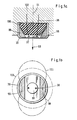
- Fig. 1a einen schematischen, nicht maßstäblichen Querschnitt durch einen Ultraschall-Sensor mit inneren Dämpfungssegmenten.
- Fig. 1b zeigt einen schematischen Einblick von hinten in einen geöffneten Utraschall-Sensor mit inneren Dämpfungssegmenten gemäß Fig. la.
- Fig. 2a zeigt eine mögliche Ausbildungsvariante des Trichters als Kreiskegel-Trichter.
- Fig. 2b zeigt eine mögliche Ausbildungsvariante des Trichters als Parabolid-Kegel-Trichter.
- Fig. 2c zeigt eine mögliche Ausbildungsvariante des Trichters als Rechteck-Kegel-Trichter.
- Fig. 2d zeigt eine mögliche Ausbildungsvariante des Trichters als Trichter mit ovalem Kegelquerschnitt.
- Fig. 3a zeigt eine Ansicht eines Sensors für ein Einwandler-System.
- Fig. 3b zeigt einen schematischen, unmaßstäblichen Horizontal-Querschnitt durch einen Sensor gemäß Fig. 3a.
- Fig. 3a zeigt einen schematischen, unmaßstäblichen Vertikal-Querschnitt durch einen Sensor gemäß Fig. 3a.
- Fig. 4a zeigt eine schematische Stirnansicht eines Zwei-Wandler-Sensors.
- Fig. 4b zeigt einen vertikalen Querschnitt durch einen Zwei-Wandler-Sensor gemäß Fig. 4a.
- Fig. 1a shows a schematic, not to scale, cross section through an ultrasonic sensor with inner damping segments.
- 1b shows a schematic view from behind of an opened ultrasound sensor with inner damping segments according to FIG.
- 2a shows a possible design variant of the funnel as a circular cone funnel.
- 2b shows a possible embodiment of the funnel as a parabolic-cone funnel.
- 2c shows a possible design variant of the funnel as a rectangular-cone funnel.
- 2d shows a possible embodiment of the funnel as a funnel with an oval conical cross section.
- 3a shows a view of a sensor for a single-transducer system.
- 3b shows a schematic, non-scale Hori zonal cross-section through a sensor according to FIG. 3a.
- FIG. 3a shows a schematic, to scale vertical cross section through a sensor according to FIG. 3a.
- 4a shows a schematic end view of a two-transducer sensor.
- 4b shows a vertical cross section through a two-transducer sensor according to FIG. 4a.
Wie sich aus den Figuren 1a und 1b ergibt, ist auf das topf- ähnliche Wandlergehäuse 39 mit relativ dickwandigem Gehäusemantel und der als dünnwandiger Gehäuseboden ausgebildeten Sende- und Empfangsmembran 37 innenseitig ein piezokeramischer Schwinger aufgeklebt, dem über die Anschlußleitung 38 elektrische Energie zugeführt wird. Membranstärke, Eigenresonanz und Erregungsfrequenz sind aufeinander abgestimmt. Der Frequenzbereich liegt zwischen 28 und 86 kHz. Als günstig für einen Wandlergehäuse-Durchmesser von ca. 25 mm hat sich eine Arbeitsfrequenz zwischen 29 und 30 kHz herausgestellt.As can be seen from FIGS. 1 a and 1 b, a piezoceramic oscillator is glued to the pot-
Innenseitig sind in das Wandlergehäuse 39 zwei horizontal gegenüberliegende, kreisabschnittsförmige Dämpfungssegmente aus Weichgummi angebracht (eingegossen oder aufvulkanisiert), die etwa 20 bis 40 % der inneren Membranfläche bedecken und auch innigen Kontakt zur inneren Gehäusewand haben.Inside the
Wird der Wandler als Sender benutzt, so ist eine Shore-Härte von 50 bis 60 Grad geeignet, wird er als Empfänger eingesetzt, so sollten 40 Grad Shore nicht überschritten werden.If the transducer is used as a transmitter, a Shore hardness of 50 to 60 degrees is suitable. If it is used as a receiver, the Shore should not exceed 40 degrees.
Bei Verwendung als Sender und Empfänger (Ein-Wandler-System) ist ein Kompromiß bei ca. 45 Grad Shore anzustreben.When used as a transmitter and receiver (one-converter system), a compromise at about 45 degrees shore should be sought.
Diese angebrachten Dämpfungssegmente bewirken, daß sich etwa der in Fig. 1b dargestellte Konturenverlauf 101 in einer mittleren Meßentfernung einstellt, ohne daß die bei ungedämpften Wandlern für den vorgesehenen Ernstfall sehr störenden Keulenzipfel und 45 Grad Lage auftreten.These attached damping segments have the effect that the
Eine theoretische Erklärung für diesen Effekt konnte bislang nicht gefunden werden, wohl auch deshalb, weil dieser mit großer Sicherheit reproduzierbare Effekt nur dann auftritt, wenn Wandlerdurchmesser, Wandlerwand- und Membranstärke, Volumen, Härte und Berührungsfläche des Dämpfungsmaterials, Eigen- und Erregerfrequenz des piezokeramischen Schwingers eng aufeinander abgestimmt sind.A theoretical explanation for this effect has so far not been found, probably because this reproducible effect only occurs if the transducer diameter, transducer wall and membrane thickness, volume, hardness and contact area of the damping material, natural and excitation frequency of the piezoceramic vibrator are closely coordinated.
Damit vom Wandlergehäuse 39 und vom Schwinger 98 möglicher Körperschall (Motorvibrationen) ferngehalten werden, ist das eigentliche Sensorgehäuse aus Weichplastik oder Weichgummi von ca. 80 Grad Shore-Härte gefertigt.So that possible structure-borne noise (engine vibrations) is kept away from the
Dadurch wird auch gleichzeitig vermieden, daß Verformungskräfte des Gehäuses durch nicht fachgerechte Montage auf den Wandler störend einwirken können.This also prevents deformation forces of the housing from interfering with the transducer due to improper installation.
Anmerkung: Aus Gründen der anschaulichen Darstellung ist in Fig. 1b die Horizontal-Achse senkrecht stehend gezeichnet.Note: For the sake of clarity, the horizontal axis is drawn vertically in Fig. 1b.
In den Figuren 2a bis 2d kann der in Fig. 1 dargestellte Wandler in Gehäuse mit aufgesetzten Trichtern der verschiedensten Formen und Querschnitte eingesetzt werden, wobei je nach Trichter-Ausbildung und Trichterlänge die durch die Dämpfungssegmente erzielte Form der Sende- und/oder Empfangskeule noch variiert werden kann.In FIGS. 2a to 2d, the transducer shown in FIG. 1 can be used in housings with attached funnels of various shapes and cross-sections, the shape of the transmitting and / or receiving lobe achieved by the damping segments still varying depending on the funnel design and funnel length can be.
Die dargestellten Querschnitte (Kreis, Rechteck oder Oval) können auch zu Trichtern mit Zwei-Ebenen-Krümmungen (z. B. Parabol-Verlauf) zusammengefügt werden.The cross-sections shown (circle, rectangle or oval) can also be combined to form funnels with two-level curvatures (e.g. parabolic curve).
In den Figuren 3a und 3b wurde in einer umfangreichen Versuchsreihe ermittelt, daß sich ein Wandler 30, der in einer Mulde 107 eines rechteckkastenförmigen Gehäuses 102 sitzt, dann eine für den vorliegenden Einsatzfall optimale zusätzliche Formung der Ausbreitungskeule ergibt, wenn die Mulde, gemessen an der Austrittsfläche, etwa 2 bis 2,5mal Wandierdurchmesser-Breite, 1,5fache Wandlerdurchmesser-Höhe und 0,7 bis 0,8fache Wandlerdurchmesser-Tiefe hat und dabei der Muldenrandwinkel 108, gemessen zur Systemachse 44, im Minimum ca. 5 Altgrad beträgt.In Figures 3a and 3b it was determined in a comprehensive series of tests that a transducer 30, which sits in a
Eine solche Ausbildung bewirkt, daß die Sende- und Empfangskeulen 101 in der Horizontalen einen großen Öffnungswinkel 48 und in der Vertikalen einen kleinen Öffnungswinkel 47 ohne die störenden Nebenzipfel haben.Such a configuration causes the transmission and
Im Gehäuse 103 können zur spannungsfreien Montage Schlitze 112 oder Bohrungen vorgesehen werden.
Wird mit einem Zwei-Wandler-System gearbeitet, so lassen sich zwei Wandlergehäuse gemäß den Figuren 3a und 3b zu einem Block vereinigen, wobei dann die obere Mulde den Ultraschall-Sender, die untere Mulde den Ultraschall-Empfänger aufnimmt (Figuren 4a und 4b).If a two-transducer system is used, two transducer housings according to FIGS. 3a and 3b can be combined to form a block, in which case the upper depression accommodates the ultrasonic transmitter and the lower depression the ultrasonic receiver (FIGS. 4a and 4b). .
Um jedoch eine direkte Kopplung zwischen Sender und Empfänger zu vermeiden, erweist sich eine querverlaufende Rinne 111 mit halbkreisförmigem Querschnitt zwischen den beiden Mulden in der Blockstirnseite als wirksame Maßnahme. Sie wurde in zahlreichen Versuchen ermittelt. Eine theoretische Erklärung konnte auch hierfür, bedingt durch die vielschichtigen Randbedingungen, noch nicht gefunden werden.However, in order to avoid a direct coupling between the transmitter and receiver, a
Claims (5)
Priority Applications (1)
| Application Number | Priority Date | Filing Date | Title |
|---|---|---|---|
| AT82108653T ATE14636T1 (en) | 1981-09-23 | 1982-09-18 | SENSOR FOR PERFORMING A DISTANCE MEASUREMENT ACCORDING TO THE ULTRASOUND ECHO PRINCIPLE. |
Applications Claiming Priority (2)
| Application Number | Priority Date | Filing Date | Title |
|---|---|---|---|
| DE3137745 | 1981-09-23 | ||
| DE19813137745 DE3137745A1 (en) | 1981-09-23 | 1981-09-23 | SENSOR FOR PERFORMING THE DISTANCE MEASUREMENT ACCORDING TO THE ULTRASONIC ECHOPRINZIP |
Publications (2)
| Publication Number | Publication Date |
|---|---|
| EP0075302A1 true EP0075302A1 (en) | 1983-03-30 |
| EP0075302B1 EP0075302B1 (en) | 1985-07-31 |
Family
ID=6142353
Family Applications (1)
| Application Number | Title | Priority Date | Filing Date |
|---|---|---|---|
| EP82108653A Expired EP0075302B1 (en) | 1981-09-23 | 1982-09-18 | Sensor for measuring distances using ultrasonic echos |
Country Status (5)
| Country | Link |
|---|---|
| US (1) | US4437032A (en) |
| EP (1) | EP0075302B1 (en) |
| JP (1) | JPS5868397A (en) |
| AT (1) | ATE14636T1 (en) |
| DE (2) | DE3137745A1 (en) |
Cited By (16)
| Publication number | Priority date | Publication date | Assignee | Title |
|---|---|---|---|---|
| GB2185817A (en) * | 1984-05-29 | 1987-07-29 | Nissan Motor | Ultrasonic rangefinder |
| EP0308899A2 (en) * | 1987-09-25 | 1989-03-29 | Siemens Aktiengesellschaft | Ultrasonic transducer with astigmatic transmission-reception characteristics |
| EP0308931A2 (en) * | 1987-09-25 | 1989-03-29 | Siemens Aktiengesellschaft | Ultrasonic transducer with astigmatic transmission-reception characteristics |
| DE3832700A1 (en) * | 1988-09-27 | 1990-03-29 | Rump Elektronik Tech | APPARATUS AND METHOD FOR THE PURPOSE OF COLLISION AND BUMPER PROTECTION OF VEHICLES |
| WO1992002795A3 (en) * | 1990-08-04 | 1992-08-06 | Bosch Gmbh Robert | Ultrasonic transducer |
| WO1993011527A1 (en) * | 1991-12-05 | 1993-06-10 | Robert Bosch Gmbh | Ultrasonic damping material |
| US5229748A (en) * | 1989-04-12 | 1993-07-20 | Siemens Aktiengesellschaft | Monitoring system for monitoring the window panes of an interior, for example a motor vehicle interior |
| WO1995002237A1 (en) * | 1993-07-09 | 1995-01-19 | Gec Marconi Ltd. | Acoustic transmitting and receiving unit |
| DE4413894A1 (en) * | 1994-04-21 | 1995-10-26 | Teves Gmbh Alfred | Ultrasonic transducer with asymmetrical radiation characteristics |
| EP0378528B1 (en) * | 1987-03-24 | 1995-11-02 | Fraunhofer-Gesellschaft Zur Förderung Der Angewandten Forschung E.V. | Process for steering a self-propelled vehicle and self-propelled vehicle |
| DE19614885C1 (en) * | 1996-04-16 | 1997-09-04 | Bosch Gmbh Robert | Sensor for sending and / or receiving acoustic signals |
| DE10009129A1 (en) * | 2000-02-26 | 2001-08-30 | Volkswagen Ag | Ultrasonic sensor has pot-shaped vibration element whose floor acts as membrane with at least two disc-shaped piezoelectric transducers attached to membrane and adjacent to each other |
| US6374676B1 (en) | 1997-10-07 | 2002-04-23 | Robert Bosch Gmbh | Ultrasonic transducer |
| EP1202249A1 (en) * | 2000-10-26 | 2002-05-02 | Imra Europe S.A. | Waterproof transducer for half-wavelength array |
| US6465935B1 (en) | 1997-06-30 | 2002-10-15 | Robert Bosch Gmbh | Ultrasonic transducer |
| DE102005003398A1 (en) * | 2005-01-24 | 2006-08-03 | Endress + Hauser Flowtec Ag | Device for determining and / or monitoring volume and / or mass flow |
Families Citing this family (42)
| Publication number | Priority date | Publication date | Assignee | Title |
|---|---|---|---|---|
| DE8337585U1 (en) * | 1983-12-29 | 1985-04-25 | SWF Auto-Electric GmbH, 7120 Bietigheim-Bissingen | Device for distance measurement, in particular for motor vehicles |
| DE3441684A1 (en) * | 1984-11-15 | 1986-05-15 | SWF Auto-Electric GmbH, 7120 Bietigheim-Bissingen | Electro-acoustic transducer |
| JPS62102182U (en) * | 1985-11-26 | 1987-06-29 | ||
| US4823042A (en) * | 1986-07-18 | 1989-04-18 | Rich-Mar Corporation | Sonic transducer and method for making the same |
| JPS6388080U (en) * | 1986-11-26 | 1988-06-08 | ||
| GB2225740B (en) * | 1988-11-19 | 1993-05-19 | Glyco Metall Werke | A method and a device for the manufacture of laminar material for slide elements |
| DE3934157C2 (en) * | 1989-10-12 | 1999-01-28 | Bosch Siemens Hausgeraete | Hob |
| DE3939387A1 (en) * | 1989-11-29 | 1991-06-06 | Swf Auto Electric Gmbh | Ultrasonic distance warning system esp. for motor vehicles - has aperture covering membrane carrying piezo-plate to eliminate group echos |
| JP2560361Y2 (en) * | 1990-12-19 | 1998-01-21 | 株式会社イナックス | Ultrasonic sensor installation structure in automatic faucet |
| DE4114180C2 (en) * | 1991-05-01 | 2003-04-03 | Microsonic Ges Fuer Mikroelekt | ultrasound transducer |
| US5230921A (en) * | 1992-08-04 | 1993-07-27 | Blacktoe Medical, Inc. | Flexible piezo-electric membrane |
| US5505205A (en) * | 1993-01-08 | 1996-04-09 | Hewlett-Packard Company | Interface element for medical ultrasound transducer |
| DE19601656B4 (en) * | 1996-01-18 | 2009-07-16 | Valeo Schalter Und Sensoren Gmbh | Steamed ultrasonic transducer |
| DE19622777A1 (en) * | 1996-06-07 | 1997-12-11 | Bosch Gmbh Robert | Sensor system for automatic relative position control |
| DE59712365D1 (en) * | 1996-08-21 | 2005-08-25 | Volkswagen Ag | Device for determining the distance of objects |
| JPH10294995A (en) * | 1997-04-21 | 1998-11-04 | Matsushita Electric Ind Co Ltd | Dripproof ultrasonic wave transmitter |
| DE19754891C1 (en) * | 1997-12-10 | 1999-07-15 | Fraunhofer Ges Forschung | Ultrasonic transducer |
| TW345132U (en) * | 1998-03-26 | 1998-11-11 | shi-xiong Li | Improved structure for sensor of car backing radar |
| US6250162B1 (en) * | 1998-04-24 | 2001-06-26 | Murata Manufacturing Co., Ltd. | Ultrasonic sensor |
| DE29808915U1 (en) * | 1998-05-16 | 1999-11-25 | Hueppe Form Raumtrennsysteme G | Room partition |
| US6268683B1 (en) * | 1999-02-26 | 2001-07-31 | M&Fc Holding Company | Transducer configurations and related method |
| US6370086B2 (en) | 1999-03-15 | 2002-04-09 | Shih-Hsiung Li | Ultrasound sensor for distance measurement |
| JP2000323959A (en) | 1999-05-14 | 2000-11-24 | Murata Mfg Co Ltd | Piezoelectric parts |
| JP2001065513A (en) * | 1999-08-26 | 2001-03-16 | Toyota Autom Loom Works Ltd | Hydraulic cylinder position detection device and industrial vehicle provided therewith |
| US7233312B2 (en) * | 2000-07-31 | 2007-06-19 | Panaseca, Inc. | System and method for optimal viewing of computer monitors to minimize eyestrain |
| US6592223B1 (en) * | 1999-10-07 | 2003-07-15 | Panaseca, Inc. | System and method for optimal viewing of computer monitors to minimize eyestrain |
| DE10159679A1 (en) * | 2001-11-30 | 2003-06-12 | Valeo Schalter & Sensoren Gmbh | Ultrasonic sensor unit and manufacturing method |
| DE10341422A1 (en) * | 2003-09-09 | 2005-03-31 | Sick Engineering Gmbh | Ultrasound transducer assembly |
| DE102004011486A1 (en) * | 2004-03-09 | 2005-09-29 | Shih-Hsiung Li | Ultrasonic sensor assembly for vehicle reversing radar, has ultrasonic sensor with two electric wires, where sensor has linear sensitive distance along its axis above preset value and sensitive angle at preset degree |
| CN1906969B (en) * | 2004-04-26 | 2010-12-29 | 松下电工株式会社 | Ultrasonic sensor |
| JP2008512142A (en) * | 2004-09-03 | 2008-04-24 | パナセカ, インコーポレイテッド | Vision Center Kiosk |
| US20100222926A1 (en) * | 2005-05-09 | 2010-09-02 | Ting-Yin Chiu | Virtual wall system |
| TWI278731B (en) * | 2005-05-09 | 2007-04-11 | Infinite Electronics Inc | Self-propelled apparatus for virtual wall system |
| EP1906383B1 (en) * | 2006-09-29 | 2013-11-13 | Tung Thih Electronic Co., Ltd. | Ultrasound transducer apparatus |
| DE102007036169B4 (en) * | 2007-08-02 | 2012-06-21 | BSH Bosch und Siemens Hausgeräte GmbH | Device with ultrasonic sensors and self-propelled robot containing such a device, in particular dust-collecting robot |
| DE102007036167B4 (en) * | 2007-08-02 | 2017-09-07 | BSH Hausgeräte GmbH | Device for holding ultrasound sensors and autonomously movable robots containing them, in particular dust-collecting robots |
| JP4915597B2 (en) * | 2008-07-28 | 2012-04-11 | パナソニック株式会社 | Ultrasonic sensor |
| DE102008040905A1 (en) * | 2008-07-31 | 2010-02-04 | Robert Bosch Gmbh | ultrasonic sensor |
| CN102667523A (en) * | 2009-12-02 | 2012-09-12 | 三菱电机株式会社 | Airborne ultrasonic sensor |
| WO2011090464A1 (en) * | 2010-01-21 | 2011-07-28 | Brown James L | Method and apparatus for detecting arc faults and their locations in enclosed electrical wiring |
| JP5099175B2 (en) * | 2010-05-28 | 2012-12-12 | 株式会社村田製作所 | Ultrasonic sensor |
| DE102012209238A1 (en) * | 2012-05-31 | 2013-12-05 | Robert Bosch Gmbh | An ultrasonic sensor and apparatus and method for measuring a distance between a vehicle and an obstacle |
Citations (5)
| Publication number | Priority date | Publication date | Assignee | Title |
|---|---|---|---|---|
| US2912605A (en) * | 1955-12-05 | 1959-11-10 | Tibbetts Lab Inc | Electromechanical transducer |
| DE1811098A1 (en) * | 1968-11-23 | 1970-06-11 | Bandelin Electronic Kg | Large-area ultrasonic radiation plate |
| US3876890A (en) * | 1974-04-24 | 1975-04-08 | Saratoga Systems | Low reflected energy transmission structure transducer head |
| US3943388A (en) * | 1974-06-27 | 1976-03-09 | Fred M. Dellorfano, Jr. | Electroacoustic transducer of the flexural vibrating diaphragm type |
| EP0048958A1 (en) * | 1980-09-25 | 1982-04-07 | Egon Gelhard | Circuit for determining and displaying when the distance between a vehicle and an obstacle falls below predetermined minimum values |
-
1981
- 1981-09-23 DE DE19813137745 patent/DE3137745A1/en not_active Withdrawn
-
1982
- 1982-09-18 EP EP82108653A patent/EP0075302B1/en not_active Expired
- 1982-09-18 DE DE8282108653T patent/DE3265088D1/en not_active Expired
- 1982-09-18 AT AT82108653T patent/ATE14636T1/en not_active IP Right Cessation
- 1982-09-22 JP JP57164145A patent/JPS5868397A/en active Granted
- 1982-09-22 US US06/421,484 patent/US4437032A/en not_active Expired - Lifetime
Patent Citations (5)
| Publication number | Priority date | Publication date | Assignee | Title |
|---|---|---|---|---|
| US2912605A (en) * | 1955-12-05 | 1959-11-10 | Tibbetts Lab Inc | Electromechanical transducer |
| DE1811098A1 (en) * | 1968-11-23 | 1970-06-11 | Bandelin Electronic Kg | Large-area ultrasonic radiation plate |
| US3876890A (en) * | 1974-04-24 | 1975-04-08 | Saratoga Systems | Low reflected energy transmission structure transducer head |
| US3943388A (en) * | 1974-06-27 | 1976-03-09 | Fred M. Dellorfano, Jr. | Electroacoustic transducer of the flexural vibrating diaphragm type |
| EP0048958A1 (en) * | 1980-09-25 | 1982-04-07 | Egon Gelhard | Circuit for determining and displaying when the distance between a vehicle and an obstacle falls below predetermined minimum values |
Cited By (25)
| Publication number | Priority date | Publication date | Assignee | Title |
|---|---|---|---|---|
| GB2186690A (en) * | 1984-05-29 | 1987-08-19 | Nissan Motor | Ultrasonic rangefinder |
| GB2185817A (en) * | 1984-05-29 | 1987-07-29 | Nissan Motor | Ultrasonic rangefinder |
| EP0378528B1 (en) * | 1987-03-24 | 1995-11-02 | Fraunhofer-Gesellschaft Zur Förderung Der Angewandten Forschung E.V. | Process for steering a self-propelled vehicle and self-propelled vehicle |
| EP0308899A2 (en) * | 1987-09-25 | 1989-03-29 | Siemens Aktiengesellschaft | Ultrasonic transducer with astigmatic transmission-reception characteristics |
| EP0308931A2 (en) * | 1987-09-25 | 1989-03-29 | Siemens Aktiengesellschaft | Ultrasonic transducer with astigmatic transmission-reception characteristics |
| US4907207A (en) * | 1987-09-25 | 1990-03-06 | Siemens Aktiengesellschaft | Ultrasound transducer having astigmatic transmission/reception characteristic |
| EP0308899A3 (en) * | 1987-09-25 | 1990-03-14 | Siemens Aktiengesellschaft | Ultrasonic transducer with astigmatic transmission-reception characteristics |
| EP0308931A3 (en) * | 1987-09-25 | 1990-03-21 | Siemens Aktiengesellschaft | Ultrasonic transducer with astigmatic transmission-reception characteristics |
| DE3832700A1 (en) * | 1988-09-27 | 1990-03-29 | Rump Elektronik Tech | APPARATUS AND METHOD FOR THE PURPOSE OF COLLISION AND BUMPER PROTECTION OF VEHICLES |
| US5229748A (en) * | 1989-04-12 | 1993-07-20 | Siemens Aktiengesellschaft | Monitoring system for monitoring the window panes of an interior, for example a motor vehicle interior |
| US5446332A (en) * | 1990-08-04 | 1995-08-29 | Robert Bosch Gmbh | Ultrasonic transducer |
| WO1992002795A3 (en) * | 1990-08-04 | 1992-08-06 | Bosch Gmbh Robert | Ultrasonic transducer |
| WO1993011527A1 (en) * | 1991-12-05 | 1993-06-10 | Robert Bosch Gmbh | Ultrasonic damping material |
| WO1995002237A1 (en) * | 1993-07-09 | 1995-01-19 | Gec Marconi Ltd. | Acoustic transmitting and receiving unit |
| DE4413894A1 (en) * | 1994-04-21 | 1995-10-26 | Teves Gmbh Alfred | Ultrasonic transducer with asymmetrical radiation characteristics |
| DE4413894C2 (en) * | 1994-04-21 | 2002-12-12 | Teves Gmbh Alfred | Bending converter in pot form |
| EP0802521A3 (en) * | 1996-04-16 | 1999-09-01 | Robert Bosch Gmbh | Transducer for sending and/or receiving of acoustic signals |
| EP0802521A2 (en) * | 1996-04-16 | 1997-10-22 | Robert Bosch Gmbh | Transducer for sending and/or receiving of acoustic signals |
| DE19614885C1 (en) * | 1996-04-16 | 1997-09-04 | Bosch Gmbh Robert | Sensor for sending and / or receiving acoustic signals |
| US6465935B1 (en) | 1997-06-30 | 2002-10-15 | Robert Bosch Gmbh | Ultrasonic transducer |
| EP0993344B2 (en) † | 1997-06-30 | 2008-10-15 | Robert Bosch Gmbh | Ultrasonic transducer |
| US6374676B1 (en) | 1997-10-07 | 2002-04-23 | Robert Bosch Gmbh | Ultrasonic transducer |
| DE10009129A1 (en) * | 2000-02-26 | 2001-08-30 | Volkswagen Ag | Ultrasonic sensor has pot-shaped vibration element whose floor acts as membrane with at least two disc-shaped piezoelectric transducers attached to membrane and adjacent to each other |
| EP1202249A1 (en) * | 2000-10-26 | 2002-05-02 | Imra Europe S.A. | Waterproof transducer for half-wavelength array |
| DE102005003398A1 (en) * | 2005-01-24 | 2006-08-03 | Endress + Hauser Flowtec Ag | Device for determining and / or monitoring volume and / or mass flow |
Also Published As
| Publication number | Publication date |
|---|---|
| US4437032A (en) | 1984-03-13 |
| JPS5868397A (en) | 1983-04-23 |
| JPH048999B2 (en) | 1992-02-18 |
| ATE14636T1 (en) | 1985-08-15 |
| DE3137745A1 (en) | 1983-04-07 |
| DE3265088D1 (en) | 1985-09-05 |
| EP0075302B1 (en) | 1985-07-31 |
Similar Documents
| Publication | Publication Date | Title |
|---|---|---|
| EP0075302B1 (en) | Sensor for measuring distances using ultrasonic echos | |
| DE4410895B4 (en) | Method and device for concealed installation of an ultrasonic sensor in an outer part of a motor vehicle | |
| EP0048958B1 (en) | Circuit for determining and displaying when the distance between a vehicle and an obstacle falls below predetermined minimum values | |
| DE3738515C2 (en) | ||
| DE4238924A1 (en) | Electroacoustic transducer | |
| DE102007047274B4 (en) | ultrasonic sensor | |
| EP1199196B1 (en) | Vehicle air suspension system with ultrasound measuring arrangement | |
| DE3441684A1 (en) | Electro-acoustic transducer | |
| DE3602351C1 (en) | Sound converter system | |
| DE19917862A1 (en) | Ultrasound sensor for object detection, e.g. for automobile driving aid | |
| DE102012209238A1 (en) | An ultrasonic sensor and apparatus and method for measuring a distance between a vehicle and an obstacle | |
| EP2440888B1 (en) | Method for measuring a measurement variable | |
| DE3721209A1 (en) | Sound/ultrasound instrument (test set, measurement apparatus) | |
| DE4306193B4 (en) | level sensor | |
| EP1308750A2 (en) | Method and device for measuring distance and pressure inside an air spring | |
| DE19614885C1 (en) | Sensor for sending and / or receiving acoustic signals | |
| EP0993344B1 (en) | Ultrasonic transducer | |
| DE4114180C2 (en) | ultrasound transducer | |
| DE19912772C2 (en) | Ultrasonic sensor for distance measurement | |
| DE2820120C2 (en) | ||
| DE102016111133A1 (en) | Device for determining or monitoring the volume and / or mass flow of a fluid medium in a pipeline | |
| EP1493302B1 (en) | Sound or ultrasound sensor | |
| DE2708226A1 (en) | Ultrasonic transceiver system with tubular transmitter - has conical reflector and horn coupled electret receiver with common axis | |
| DE19643956A1 (en) | Ultrasonic fluid level sensor for fluid in container | |
| DE102005013269A1 (en) | Method for determining the liquid level of a liquid phase via an ultrasonic transit time measurement |
Legal Events
| Date | Code | Title | Description |
|---|---|---|---|
| PUAI | Public reference made under article 153(3) epc to a published international application that has entered the european phase |
Free format text: ORIGINAL CODE: 0009012 |
|
| AK | Designated contracting states |
Designated state(s): AT BE CH DE FR GB IT LI LU NL SE |
|
| 17P | Request for examination filed |
Effective date: 19830924 |
|
| ITF | It: translation for a ep patent filed |
Owner name: STUDIO JAUMANN |
|
| GRAA | (expected) grant |
Free format text: ORIGINAL CODE: 0009210 |
|
| RAP1 | Party data changed (applicant data changed or rights of an application transferred) |
Owner name: GELHARD, EGON |
|
| RAP1 | Party data changed (applicant data changed or rights of an application transferred) |
Owner name: GELHARD, EGON |
|
| AK | Designated contracting states |
Designated state(s): AT BE CH DE FR GB IT LI LU NL SE |
|
| PG25 | Lapsed in a contracting state [announced via postgrant information from national office to epo] |
Ref country code: SE Effective date: 19850731 |
|
| REF | Corresponds to: |
Ref document number: 14636 Country of ref document: AT Date of ref document: 19850815 Kind code of ref document: T |
|
| REF | Corresponds to: |
Ref document number: 3265088 Country of ref document: DE Date of ref document: 19850905 |
|
| ET | Fr: translation filed | ||
| PLBE | No opposition filed within time limit |
Free format text: ORIGINAL CODE: 0009261 |
|
| STAA | Information on the status of an ep patent application or granted ep patent |
Free format text: STATUS: NO OPPOSITION FILED WITHIN TIME LIMIT |
|
| 26N | No opposition filed | ||
| GBPC | Gb: european patent ceased through non-payment of renewal fee | ||
| REG | Reference to a national code |
Ref country code: FR Ref legal event code: ST |
|
| PG25 | Lapsed in a contracting state [announced via postgrant information from national office to epo] |
Ref country code: GB Free format text: LAPSE BECAUSE OF NON-PAYMENT OF DUE FEES Effective date: 19881121 |
|
| REG | Reference to a national code |
Ref country code: FR Ref legal event code: AR |
|
| REG | Reference to a national code |
Ref country code: FR Ref legal event code: BR |
|
| ITTA | It: last paid annual fee | ||
| REG | Reference to a national code |
Ref country code: FR Ref legal event code: ST |
|
| REG | Reference to a national code |
Ref country code: FR Ref legal event code: RC |
|
| REG | Reference to a national code |
Ref country code: FR Ref legal event code: DA |
|
| EPTA | Lu: last paid annual fee | ||
| PGFP | Annual fee paid to national office [announced via postgrant information from national office to epo] |
Ref country code: AT Payment date: 19990318 Year of fee payment: 17 |
|
| PG25 | Lapsed in a contracting state [announced via postgrant information from national office to epo] |
Ref country code: AT Free format text: LAPSE BECAUSE OF NON-PAYMENT OF DUE FEES Effective date: 19990918 |
|
| PGFP | Annual fee paid to national office [announced via postgrant information from national office to epo] |
Ref country code: CH Payment date: 20000322 Year of fee payment: 18 |
|
| PGFP | Annual fee paid to national office [announced via postgrant information from national office to epo] |
Ref country code: NL Payment date: 20000328 Year of fee payment: 18 |
|
| PGFP | Annual fee paid to national office [announced via postgrant information from national office to epo] |
Ref country code: LU Payment date: 20000404 Year of fee payment: 18 |
|
| PGFP | Annual fee paid to national office [announced via postgrant information from national office to epo] |
Ref country code: BE Payment date: 20000405 Year of fee payment: 18 |
|
| PG25 | Lapsed in a contracting state [announced via postgrant information from national office to epo] |
Ref country code: LU Free format text: LAPSE BECAUSE OF NON-PAYMENT OF DUE FEES Effective date: 20000918 |
|
| PG25 | Lapsed in a contracting state [announced via postgrant information from national office to epo] |
Ref country code: LI Free format text: LAPSE BECAUSE OF NON-PAYMENT OF DUE FEES Effective date: 20000930 Ref country code: CH Free format text: LAPSE BECAUSE OF NON-PAYMENT OF DUE FEES Effective date: 20000930 Ref country code: BE Free format text: LAPSE BECAUSE OF NON-PAYMENT OF DUE FEES Effective date: 20000930 |
|
| BERE | Be: lapsed |
Owner name: GELHARD EGON Effective date: 20000930 |
|
| PG25 | Lapsed in a contracting state [announced via postgrant information from national office to epo] |
Ref country code: NL Free format text: LAPSE BECAUSE OF NON-PAYMENT OF DUE FEES Effective date: 20010401 |
|
| REG | Reference to a national code |
Ref country code: CH Ref legal event code: PL |
|
| NLV4 | Nl: lapsed or anulled due to non-payment of the annual fee |
Effective date: 20010401 |
|
| PGFP | Annual fee paid to national office [announced via postgrant information from national office to epo] |
Ref country code: DE Payment date: 20010903 Year of fee payment: 20 |
|
| PGFP | Annual fee paid to national office [announced via postgrant information from national office to epo] |
Ref country code: FR Payment date: 20010904 Year of fee payment: 20 |