EP0631232A2 - Integration of systems management services with an underlying system object model - Google Patents
Integration of systems management services with an underlying system object model Download PDFInfo
- Publication number
- EP0631232A2 EP0631232A2 EP94109761A EP94109761A EP0631232A2 EP 0631232 A2 EP0631232 A2 EP 0631232A2 EP 94109761 A EP94109761 A EP 94109761A EP 94109761 A EP94109761 A EP 94109761A EP 0631232 A2 EP0631232 A2 EP 0631232A2
- Authority
- EP
- European Patent Office
- Prior art keywords
- objects
- internal state
- data processing
- storing
- memory device
- Prior art date
- Legal status (The legal status is an assumption and is not a legal conclusion. Google has not performed a legal analysis and makes no representation as to the accuracy of the status listed.)
- Granted
Links
Images


Classifications
-
- G—PHYSICS
- G06—COMPUTING; CALCULATING OR COUNTING
- G06F—ELECTRIC DIGITAL DATA PROCESSING
- G06F9/00—Arrangements for program control, e.g. control units
- G06F9/06—Arrangements for program control, e.g. control units using stored programs, i.e. using an internal store of processing equipment to receive or retain programs
- G06F9/46—Multiprogramming arrangements
- G06F9/465—Distributed object oriented systems
Definitions
- the present invention relates generally to data processing systems and, more particularly, to the integration of system management services with an underlying system object model.
- a method is practiced in a distributed system having at least one memory device and processors for running processes.
- the internal state of a managed component is represented as an object in one of the memory devices.
- the object is visible to the processes on the processors.
- the object is then accessed on behalf of one of the processes to obtain the internal state of the managed component.
- the managed component may be partitioned into a single subcomponent or into multiple subcomponents. Each of the subcomponents has an internal state. Furthermore, the method may include the additional step of encapsulating the object into a container object for the component.
- the container object is stored in one of the memory devices and is visible to processes run on the processor. The method is adaptable to use with multiple components to be managed.
- a system management object may be stored in the memory devices. The system management object manages the managed component.
- a distributed system includes memory devices and processors for running processes.
- the distributed system also includes a component to be managed that has an internal state.
- the distributed system includes a means for storing the internal state of the component in the memory device as an object.
- the distributed system further includes a means for making the object accessible by the processes run on the processors.
- a method is practiced on a distributed system having a remote procedure call facility, a first data processing system and a second data processing system.
- the first data processing system includes a processor running a process.
- the second data processing system includes a component having a state and a memory device.
- an object is stored in the memory device of the second data processing system.
- the object holds the state of the component.
- the process running on the processor of the first data processing system requests access to the state of the component that is held in the object.
- a remote procedure call is performed using the remote procedure call facility to gain access by the process to the information about the state of the component held in the object.
- a method is practiced in a distributed system having storage devices for storing objects having names, processors running programs having states and an operating system.
- the operating system includes a name service which provides a global name space for the names of objects stored in the storage devices.
- a variable is declared in a program to be a variable whose value is available in the global name space.
- the program is run on one of the processors so that the variable is assigned a value, and the value is stored in the object that is visible in the global name space.
- the variable may be a counter that is incremented in predetermined quantities, a meter whose value varies over a predetermined range or any other variable that holds state information about the program.
- a method is practiced in a distributed system having data processing resources and at least one memory device.
- the data processing resources which may include hardware components and/or software components, are modeled as objects with names.
- the named objects are stored in the memory device.
- System management objects having names are also stored in the memory device. The system management objects are used to manage the data processing resources.
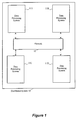
- Figure 1 is a block diagram of a distributed system for practicing a preferred embodiment of the present invention.
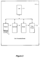
- FIG. 2 is a block diagram of a data processing system of the distributed system of Figure 1.
- FIG. 3 is a block diagram illustrating in more detail two data processing systems in the distributed system of Figure 1.
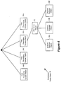
- Figure 4 is a diagram illustrating a distributed name space generated in accordance with the preferred embodiment of the present invention.
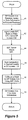
- Figure 5 is a flow chart illustrating the steps performed by the preferred embodiment of the present invention to allow sharing of internal state information across the distributed system of Figure 1.
- Figure 6 is a flow chart illustrating the steps performed to use an instrument in the distributed system of Figure 1.
- FIG. 1 shows a block diagram of a distributed system 10 for practicing the preferred embodiment of the present invention.
- the distributed system 10 includes four data processing systems 11A, 11B, 11C and 11D.
- the data processing systems 11A, 11B, 11C and 11D communicate with each other over a network 12, such as a local area network (LAN).
- LAN local area network
- FIG. 2 shows a more detailed block diagram of data processing system 11A.
- Data processing system 11A includes a central processing unit (CPU) 14, a memory 16, a keyboard 18, a mouse 20 and a video display 22.
- the memory 16 holds a copy of an object-oriented operating system 24.
- a separate copy of the operating system 24 is run by each of the data processing systems 11A, 11B, 11C and 11D ( Figure 1).
- the operating system 24 is divisible into a number of subsystems, including a systems management subsystem that is responsible for managing components of the system.
- the systems management subsystem is the focus of the discussion below.
- a first object-oriented concept employed by the preferred embodiment is the notion of an "object.”
- An "object” is an entity that is a combination of at least two things: data that specifies an internal state of the object and functions that act upon the data.
- An object may be viewed as a combination of data structures and functions. The functions are restricted to operate only upon the elements of the data structure.
- An "interface” is a group of semantically related functions that are organized into a named unit (the name being the identifier of the interface). Interfaces, by definition, have no instantiation (i.e., an interface does not include code for implementing the functions that are identified in the interface); rather, interfaces specify a set of signatures for functions. "Instantiation” refers to the process of creating in-memory structures that represent an object so that operations can be invoked on the object.
- an object "supports” an interface, the object provides code for the functions specified by the interface.
- the object that supports the interface is responsible for providing the code for implementing the functions of the interface.
- the code that is provided must comply with the signatures of the functions specified by the interface (i.e., the code must have the same parameters and functionality as specified in the interface). Accordingly, an interface may be viewed as a standard with which objects must comply.
- a "moniker” is a composite name for an object that includes a pointer to the object.
- a more formal definition of a moniker is an object that supports the IMoniker interface (as specified by the Microsoft OLE 2.0 protocol).
- the IMoniker interface includes a function for binding the moniker to the object to which the pointer of the moniker points. Binding gets an object into a running state so that services supplied by the object may be invoked. It should be appreciated that the present invention is not limited to embodiments that use monikers. The discussion of monikers in the preferred embodiment is merely illustrative.
- the preferred embodiment of the present invention integrates the system management subsystem into the underlying object model of the object-oriented operating system 24.
- the operating system models components of the distributed system 10 as objects and the system management subsystem is integrated into the objects.
- the integration of the system management subsystem with the underlying system object model provides a unified approach to accessing system management functions.
- the integration facilitates use of tools in the system management subsystem that are provided by other subsystems of the operating system 24.
- the integration allows the system management subsystem to easily gain access to internal state information about managed components that are modeled as objects.
- the cumulative result of the integration is a substantial lessening in the burden imposed on the system management subsystem and a substantial increase in the powers available to the system management subsystem.
- Systems management is provided in the preferred embodiment of the present invention by allowing system components to be constructed so that they are readily manageable and by providing utilities for managing the system components.
- Each system component in the distributed system 10 is modeled as an object.
- Subcomponents of a component may also be separately modeled as objects.
- System components are made to be manageable by encapsulating the components and subcomponents into objects that are visible in the global name space.
- the subcomponents and components include properties that specify state information. Since the state information is held in an object which is visible in the global distributed name space, other objects are able to gain access to the state information.
- the components and subcomponents are modeled as objects, they are readily located and accessed.
- each managed object supports interfaces that provide services to other client objects.
- the operation of the systems management subsystem of the preferred embodiment is perhaps best explained by way of example.
- the system management subsystem is not isolated on a single one of the data processing systems 11A, 11B, 11C and 11D. Rather, the responsibilities of the system management subsystem are shared among the data processing systems 11A, 11B, 11C and 11D so that the data processing systems jointly perform systems management.
- FIG 3 suppose that data processing system 11A, in performing system management functions, wishes to find out additional information about the state of a file server 26, which is held remotely in memory 16' of data processing system 11B.
- the file server 26 is the managed component that the system management subsystem seeks to manage.
- the state of the file server 26 is partitioned for convenience into a number of subcomponents.
- the file server 26 is partitioned into a request receiver, a request processor and a result returner.
- the request receiver is responsible for receiving requests for service from the file server.
- the request processor is responsible for processing such requests, and the result returner is responsible for returning the results of the service to the client that requested the service.
- the set of subcomponents included in a managed component need not remain the same; rather, the subcomponents may change dynamically over time such that subcomponents are added and deleted as time progresses. It should also be appreciated that the subcomponents may be organized hierarchically.
- the CPU 14' of data processing system 11B makes information about the file server 26 and its subcomponents available to other components in the distributed system 10 ( Figure 1) by creating an object 32 for the file server and objects 34A, 34B and 34C for the subcomponents that hold state information about the file server and its subcomponents as illustrated in Figure 4. These objects 32, 34A, 34B and 34C are visible in a distributed name space 28.
- Each of the data processing systems 11A, 11B, 11C and 11D ( Figure 1) in the distributed system 10 has access to the objects in the distributed name space 28 ( Figure 4).
- the distributed name space 28 also includes objects 30A, 30B, 30C and 30D that model the data processing systems 11A, 11B, 11C and 11D, respectively.
- the file server object 32 is a "container.”
- a container is an entity that contains other objects.
- the file server object 32 is a container that contains objects 34A, 34B and 34C for the respective subcomponents of the file server 26.
- a managed component may be modeled as a container object that holds objects for the subcomponents of the managed object.
- the file server object 32 is also a special type of object, known as a junction point, that differs from other objects in the distributed name space 28.
- a junction point is an object that serves as a junction between two name spaces.
- the file server object 32 is a junction point that joins the distributed name space with the name space of the subcomponents objects 34A, 34B and 34C. Access to subcomponents objects 34A, 34B and 34C may be made through the file server container object 32.
- Each of the subcomponent objects 34A, 34B and 34C supports an interface for monitoring and managing its behavior. Further, each of the subcomponent objects 34A, 34B and 34C holds state information regarding the respective subcomponent associated with the object. This state information is held in property sets stored in the subcomponent objects 34A, 34B and 34C, which may be queried to obtain the state information contained therein.
- the junction point for the file server object 32 stores a globally unique ID (GUID) for the file server object 32. This GUID is used to uniquely identify the file server object 32 in the distributed name space 28.
- GUID globally unique ID
- RPC current remote procedure call
- the agent is a body of library code provided by the operating system 24 that serves multiple purposes, including making the subcomponent objects 34A, 34B and 34C visible in the distributed global name space 28.
- the agent also provides a remote procedure call (RPC) server for making remote procedure calls on behalf of the file server and its subcomponents. There is a direct one-to-one correspondence between a managed component, such as the file server, and its agent.
- the operating system 24 provides application program interfaces (APIs) that allow a user to create a new agent, create objects for managed components and subcomponents, delete objects for managed components and subcomponents, and provide a response to operations on managed components and subcomponents.
- APIs application program interfaces
- the agent is able to retrieve values of selected properties of a managed object, and the agent is able to modify the values of properties held in managed objects.
- FIG 5 shows a flow chart of the steps performed to gain access to the status information held in the request processor object 34B.
- data processing system 11A requests access to state information that is held in the request processor subcomponent object 34B (step 40 in Figure 5).
- the operating system 24 Figure 2 recognizes that the request processor subcomponent object 34B is a remote object that is stored in data processing system 11B.
- the agent for the subcomponent objects 34A, 34B and 34C is called on data processing system 11B using an RPC facility that is provided as part of the operating system 24.
- the agent loads RPC stub routines that package data and use the RPC facility to make the RPC call to data processing system 11B. Two sets of stub routines are loaded.
- a set of stub routines is loaded at data processing system 11A to make the RPC call
- a set of stub routines is loaded at data processing system 11B to make the callback to data processing system 11A (step 42 in Figure 5).
- the RPC stub routines at data processing system 11A are then executed to invoke the RPC server of the agent, which makes the RPC call (step 44).
- the status information is queried locally at data processing system 11B (step 46 of Figure 5).
- the status information is queried by first finding a moniker for an interface supported by the request processor subcomponent object 34B ( Figure 4) and which allows querying of the status information held in the request processor subcomponent object. This moniker is obtained using the QueryInterface() function.
- the IUnknown interface includes the function, QueryInterface (), for querying whether an object supports a particular interface.
- the QueryInterface() function returns to obtain a pointer to the code for implementing the functions. In general, whenever a function is called that is part of an interface supported by an object, the QueryInterface() function must first be called.
- the moniker obtained by calling the QueryInterface() function points to an instance of the interface that is supported by the request processor subcomponent object 34B ( Figure 4). The moniker is then used to access functions for querying status information held in the request processor subcomponent object 34B.
- the preferred embodiment encapsulates state information for managed components into objects that are visible in the distributed name space so that remote access to the state information is possible.
- the state information is integrated into the underlying system object model, the objects holding the state information may be manipulated and managed using tools that may be employed with all types of objects.
- the operating system 24 of the preferred embodiment of the present invention provides at least two kinds of "instruments.” Instruments are variables whose value is visible in the distributed name space 28.
- Figure 6 is a flow chart showing how instruments are used in the preferred embodiment of the present invention. Initially, a variable is declared as an instrument within an application program (step 52 in Figure 6). The application program then assigns a value to the instrument during its execution (step 54). The value assigned to the instrument is encapsulated into a corresponding object that is visible in the distributed name space 28 (step 56). Accordingly, the value of the instrument may be obtained by querying the corresponding object.
- Instruments are available in three varieties. A user specifies which variety of instrument he wants in the variable type declaration.
- a first variety of instrument is a counter. The counter acts in a fashion analogous to an odometer in that it is always increases in value until it is reset.
- a second variety of instrument is a meter instrument that acts like a meter which may fluctuate between a range of values.
- the preferred embodiment of the present invention also provides an additional mechanism for placing state information in the distributed name space 28.
- This mechanism is known as a workstation management agent.
- the workstation management agent puts the current state of a workstation into the distributed global name space 28.
Abstract
Description
- The present invention relates generally to data processing systems and, more particularly, to the integration of system management services with an underlying system object model.
- In order for system management functions to properly perform their intended roles, the functions must be able to monitor the internal state of components that they manage. Conventional systems have not had access to the internal state of managed components. As a result, it has often been difficult for conventional systems to properly manage the components. Certain conventional systems have attempted to increase access to information concerning managed components by adding a separate framework and access technique for the internal state information. Such conventional systems, however, have not made the internal state information generally available through standard user-visible system interfaces and human interfaces.
- In accordance with a first aspect of the present invention, a method is practiced in a distributed system having at least one memory device and processors for running processes. In this method, the internal state of a managed component is represented as an object in one of the memory devices. The object is visible to the processes on the processors. The object is then accessed on behalf of one of the processes to obtain the internal state of the managed component.
- The managed component may be partitioned into a single subcomponent or into multiple subcomponents. Each of the subcomponents has an internal state. Furthermore, the method may include the additional step of encapsulating the object into a container object for the component. The container object is stored in one of the memory devices and is visible to processes run on the processor. The method is adaptable to use with multiple components to be managed. A system management object may be stored in the memory devices. The system management object manages the managed component.
- In accordance with another aspect of the present invention, a distributed system includes memory devices and processors for running processes. The distributed system also includes a component to be managed that has an internal state. The distributed system includes a means for storing the internal state of the component in the memory device as an object. The distributed system further includes a means for making the object accessible by the processes run on the processors.
- In accordance with yet another aspect of the present invention, a method is practiced on a distributed system having a remote procedure call facility, a first data processing system and a second data processing system. The first data processing system includes a processor running a process. The second data processing system includes a component having a state and a memory device. In this method, an object is stored in the memory device of the second data processing system. The object holds the state of the component. The process running on the processor of the first data processing system requests access to the state of the component that is held in the object. In response to the request, a remote procedure call is performed using the remote procedure call facility to gain access by the process to the information about the state of the component held in the object.
- In accordance with a still further aspect of the present invention, a method is practiced in a distributed system having storage devices for storing objects having names, processors running programs having states and an operating system. The operating system includes a name service which provides a global name space for the names of objects stored in the storage devices. In this method, a variable is declared in a program to be a variable whose value is available in the global name space. The program is run on one of the processors so that the variable is assigned a value, and the value is stored in the object that is visible in the global name space. The variable may be a counter that is incremented in predetermined quantities, a meter whose value varies over a predetermined range or any other variable that holds state information about the program.
- In accordance with an additional aspect of the present invention, a method is practiced in a distributed system having data processing resources and at least one memory device. In this method, the data processing resources, which may include hardware components and/or software components, are modeled as objects with names. The named objects are stored in the memory device. System management objects having names are also stored in the memory device. The system management objects are used to manage the data processing resources.
- Figure 1 is a block diagram of a distributed system for practicing a preferred embodiment of the present invention.
- Figure 2 is a block diagram of a data processing system of the distributed system of Figure 1.
- Figure 3 is a block diagram illustrating in more detail two data processing systems in the distributed system of Figure 1.
- Figure 4 is a diagram illustrating a distributed name space generated in accordance with the preferred embodiment of the present invention.
- Figure 5 is a flow chart illustrating the steps performed by the preferred embodiment of the present invention to allow sharing of internal state information across the distributed system of Figure 1.
- Figure 6 is a flow chart illustrating the steps performed to use an instrument in the distributed system of Figure 1.
- A preferred embodiment of the present invention integrates system management services with an underlying system object model. Figure 1 shows a block diagram of a distributed system 10 for practicing the preferred embodiment of the present invention. Those skilled in the art will recognize that the distributed system 10 of Figure 1 is merely illustrative and will appreciate that the present invention may be practiced in other distributed systems. The distributed system 10 includes four
data processing systems data processing systems network 12, such as a local area network (LAN). - Figure 2 shows a more detailed block diagram of
data processing system 11A. For purposes of simplicity in the discussion below, it will be assumed thatdata processing systems Data processing system 11A includes a central processing unit (CPU) 14, amemory 16, akeyboard 18, amouse 20 and avideo display 22. Thememory 16 holds a copy of an object-oriented operating system 24. A separate copy of theoperating system 24 is run by each of thedata processing systems operating system 24 is divisible into a number of subsystems, including a systems management subsystem that is responsible for managing components of the system. The systems management subsystem is the focus of the discussion below. - In order for one to understand how the preferred embodiment of the present invention operates, it is necessary for one to first understand certain object-oriented programming concepts that are employed therein. A first object-oriented concept employed by the preferred embodiment is the notion of an "object." An "object" is an entity that is a combination of at least two things: data that specifies an internal state of the object and functions that act upon the data. An object may be viewed as a combination of data structures and functions. The functions are restricted to operate only upon the elements of the data structure.
- A closely related concept is the concept of an "interface". An "interface" is a group of semantically related functions that are organized into a named unit (the name being the identifier of the interface). Interfaces, by definition, have no instantiation (i.e., an interface does not include code for implementing the functions that are identified in the interface); rather, interfaces specify a set of signatures for functions. "Instantiation" refers to the process of creating in-memory structures that represent an object so that operations can be invoked on the object. When an object "supports" an interface, the object provides code for the functions specified by the interface. Thus, the object that supports the interface is responsible for providing the code for implementing the functions of the interface. The code that is provided must comply with the signatures of the functions specified by the interface (i.e., the code must have the same parameters and functionality as specified in the interface). Accordingly, an interface may be viewed as a standard with which objects must comply.
- Another concept employed in the preferred embodiment is the notion of a "moniker". A "moniker" is a composite name for an object that includes a pointer to the object. A more formal definition of a moniker is an object that supports the IMoniker interface (as specified by the Microsoft OLE 2.0 protocol). The IMoniker interface includes a function for binding the moniker to the object to which the pointer of the moniker points. Binding gets an object into a running state so that services supplied by the object may be invoked. It should be appreciated that the present invention is not limited to embodiments that use monikers. The discussion of monikers in the preferred embodiment is merely illustrative.
- As mentioned above, the preferred embodiment of the present invention integrates the system management subsystem into the underlying object model of the object-oriented
operating system 24. In other words, the operating system models components of the distributed system 10 as objects and the system management subsystem is integrated into the objects. The integration of the system management subsystem with the underlying system object model provides a unified approach to accessing system management functions. Moreover, the integration facilitates use of tools in the system management subsystem that are provided by other subsystems of theoperating system 24. Still further, the integration allows the system management subsystem to easily gain access to internal state information about managed components that are modeled as objects. The cumulative result of the integration is a substantial lessening in the burden imposed on the system management subsystem and a substantial increase in the powers available to the system management subsystem. - Systems management is provided in the preferred embodiment of the present invention by allowing system components to be constructed so that they are readily manageable and by providing utilities for managing the system components. Each system component in the distributed system 10 is modeled as an object. Subcomponents of a component may also be separately modeled as objects. System components are made to be manageable by encapsulating the components and subcomponents into objects that are visible in the global name space. The subcomponents and components include properties that specify state information. Since the state information is held in an object which is visible in the global distributed name space, other objects are able to gain access to the state information. Moreover, since the components and subcomponents are modeled as objects, they are readily located and accessed. In general, each managed object supports interfaces that provide services to other client objects.
- The operation of the systems management subsystem of the preferred embodiment is perhaps best explained by way of example. The system management subsystem is not isolated on a single one of the
data processing systems data processing systems data processing system 11A, in performing system management functions, wishes to find out additional information about the state of afile server 26, which is held remotely in memory 16' ofdata processing system 11B. In this example, thefile server 26 is the managed component that the system management subsystem seeks to manage. The state of thefile server 26 is partitioned for convenience into a number of subcomponents. In particular, thefile server 26 is partitioned into a request receiver, a request processor and a result returner. The request receiver is responsible for receiving requests for service from the file server. The request processor is responsible for processing such requests, and the result returner is responsible for returning the results of the service to the client that requested the service. - It should be appreciated that the set of subcomponents included in a managed component need not remain the same; rather, the subcomponents may change dynamically over time such that subcomponents are added and deleted as time progresses. It should also be appreciated that the subcomponents may be organized hierarchically.
- The CPU 14' of
data processing system 11B makes information about thefile server 26 and its subcomponents available to other components in the distributed system 10 (Figure 1) by creating anobject 32 for the file server and objects 34A, 34B and 34C for the subcomponents that hold state information about the file server and its subcomponents as illustrated in Figure 4. Theseobjects name space 28. Each of thedata processing systems name space 28 also includesobjects data processing systems - The
file server object 32 is a "container." A container is an entity that contains other objects. In the example of Figure 4, thefile server object 32 is a container that containsobjects file server 26. Hence, a managed component may be modeled as a container object that holds objects for the subcomponents of the managed object. - The
file server object 32 is also a special type of object, known as a junction point, that differs from other objects in the distributedname space 28. A junction point is an object that serves as a junction between two name spaces. Thefile server object 32 is a junction point that joins the distributed name space with the name space of the subcomponents objects 34A, 34B and 34C. Access to subcomponents objects 34A, 34B and 34C may be made through the fileserver container object 32. Each of the subcomponent objects 34A, 34B and 34C supports an interface for monitoring and managing its behavior. Further, each of the subcomponent objects 34A, 34B and 34C holds state information regarding the respective subcomponent associated with the object. This state information is held in property sets stored in the subcomponent objects 34A, 34B and 34C, which may be queried to obtain the state information contained therein. - The junction point for the
file server object 32 stores a globally unique ID (GUID) for thefile server object 32. This GUID is used to uniquely identify thefile server object 32 in the distributedname space 28. In addition, a current remote procedure call (RPC) address for an "agent" of thefile server 26 is stored in thefile server object 32. The agent is a body of library code provided by theoperating system 24 that serves multiple purposes, including making the subcomponent objects 34A, 34B and 34C visible in the distributedglobal name space 28. The agent also provides a remote procedure call (RPC) server for making remote procedure calls on behalf of the file server and its subcomponents. There is a direct one-to-one correspondence between a managed component, such as the file server, and its agent. Theoperating system 24 provides application program interfaces (APIs) that allow a user to create a new agent, create objects for managed components and subcomponents, delete objects for managed components and subcomponents, and provide a response to operations on managed components and subcomponents. The agent is able to retrieve values of selected properties of a managed object, and the agent is able to modify the values of properties held in managed objects. - Returning to the example of Figure 4, suppose that
data processing system 11A seeks access to the requestprocessor subcomponent object 34B. Figure 5 shows a flow chart of the steps performed to gain access to the status information held in therequest processor object 34B. Initially,data processing system 11A requests access to state information that is held in the requestprocessor subcomponent object 34B (step 40 in Figure 5). The operating system 24 (Figure 2) recognizes that the requestprocessor subcomponent object 34B is a remote object that is stored indata processing system 11B. As a result, the agent for the subcomponent objects 34A, 34B and 34C is called ondata processing system 11B using an RPC facility that is provided as part of theoperating system 24. The agent, in turn, loads RPC stub routines that package data and use the RPC facility to make the RPC call todata processing system 11B. Two sets of stub routines are loaded. - First, a set of stub routines is loaded at
data processing system 11A to make the RPC call, and second, a set of stub routines is loaded atdata processing system 11B to make the callback todata processing system 11A (step 42 in Figure 5). The RPC stub routines atdata processing system 11A are then executed to invoke the RPC server of the agent, which makes the RPC call (step 44). The status information is queried locally atdata processing system 11B (step 46 of Figure 5). The status information is queried by first finding a moniker for an interface supported by the requestprocessor subcomponent object 34B (Figure 4) and which allows querying of the status information held in the request processor subcomponent object. This moniker is obtained using the QueryInterface() function. - Each object in the distributed
name space 28, by definition, must support the IUnknown interface (i.e., all objects support interfaces that inherit the IUnknown interface). The IUnknown interface includes the function, QueryInterface (), for querying whether an object supports a particular interface. The QueryInterface() function returns to obtain a pointer to the code for implementing the functions. In general, whenever a function is called that is part of an interface supported by an object, the QueryInterface() function must first be called. - The moniker obtained by calling the QueryInterface() function points to an instance of the interface that is supported by the request
processor subcomponent object 34B (Figure 4). The moniker is then used to access functions for querying status information held in the requestprocessor subcomponent object 34B. - Once the status information has been obtained locally at
data processing system 11B, a callback is made todata processing system 11A using the RPC stub routines that were loaded earlier (step 48 in Figure 5).Data processing system 11A then receives the status information and uses the status information for systems management functions (step 50 in Figure 5). - The above-described example illustrates how the preferred embodiment of the present invention eases system management tasks. In particular, the preferred embodiment encapsulates state information for managed components into objects that are visible in the distributed name space so that remote access to the state information is possible. Moreover, since the state information is integrated into the underlying system object model, the objects holding the state information may be manipulated and managed using tools that may be employed with all types of objects.
- The
operating system 24 of the preferred embodiment of the present invention provides at least two kinds of "instruments." Instruments are variables whose value is visible in the distributedname space 28. Figure 6 is a flow chart showing how instruments are used in the preferred embodiment of the present invention. Initially, a variable is declared as an instrument within an application program (step 52 in Figure 6). The application program then assigns a value to the instrument during its execution (step 54). The value assigned to the instrument is encapsulated into a corresponding object that is visible in the distributed name space 28 (step 56). Accordingly, the value of the instrument may be obtained by querying the corresponding object. - Instruments are available in three varieties. A user specifies which variety of instrument he wants in the variable type declaration. A first variety of instrument is a counter. The counter acts in a fashion analogous to an odometer in that it is always increases in value until it is reset. Similarly, a second variety of instrument is a meter instrument that acts like a meter which may fluctuate between a range of values.
- The preferred embodiment of the present invention also provides an additional mechanism for placing state information in the distributed
name space 28. This mechanism is known as a workstation management agent. The workstation management agent puts the current state of a workstation into the distributedglobal name space 28. - While the present invention has been described with reference to a preferred embodiment thereof, those skilled in the art will, nevertheless, appreciate that various changes in form and detail may be made without departing from the present invention as defined in the appended claims. For instance, the present invention need not use interfaces or monikers; rather, other alternative mechanisms may be used.
Claims (17)
- In a distributed system having at least one memory device, processors for running processes and a managed component with an internal state, a method comprising the steps of:
storing the internal state of the managed component as part of an object in one of the memory devices, the object being visible to the processes run on the processors; and
accessing the object stored in the memory device to gain access to the internal state of the managed component by one of the processes. - The method recited in claim 1, further comprising the step of partitioning the managed component into multiple subcomponents which each have an internal state and storing the internal state of each of the subcomponents in a separate object in at least one of the memory devices, each object being visible to the processes run on the processors.
- The method recited in claim 2, further comprising the step of encapsulating the objects which store the internal states of the subcomponents into the object that stores the internal state of the managed component so that the objects which store the internal states of the subcomponents may be accessed through the object that stores the internal state of the component.
- The method recited in claim 1 wherein the distributed system includes a second managed component with an internal state and the method further comprises the step of storing the internal state of the second component as an object, in one of the memory devices, that is visible to the processes run on the processors.
- The method recited in claim 1, further comprising the step of storing at least one system management object in the memory device for managing the managed component.
- A distributed system comprising:
memory devices;
processors for running processes;
a managed component with an internal state;
means for storing the internal state of the managed component in an object in one of the memory devices; and
means for making the object stored in the memory device accessible by the processes run on the processors. - The distributed system recited in claim 6, further comprising means for accessing the object in the memory device to obtain information about the internal state of the managed component.
- The distributed system recited in claim 6, further comprising means for partitioning the internal state of the managed component into multiple partitions and means for storing the partitions of the internal state in separate objects in at least one of the memory devices and wherein the means for making the object in the memory devices accessible by the processes further comprises means for making the objects storing the partitions accessible by the processes run on the processors.
- The distributed system recited in claim 6, further comprising means for storing at least one system management object for managing the managed component in the memory devices.
- In a distributed system having a remote procedure call facility, a first data processing system having a processor running a process and a second data processing system having a memory device and a component with an internal state, a method comprising the steps of:
storing an object holding information about the internal state of the component in the memory device of the second data processing system;
requesting access in the process running on the processor of the first data processing system to the information about the internal state of the component that is held in the object which is stored in the memory device; and
in response to the step of requesting access, performing a remote procedure call using the remote procedure call facility to gain access on behalf of the process to the internal state of the component that is held in the object which is stored in the memory device. - In a distributed system having processors for running programs, having states, storage devices for storing objects having names, and an operating system having a name service which provides a global name space for the names of the objects stored in the storage devices, a method comprising the steps of:(a) declaring a variable in a program to be a variable having a value that is accessible in the global name space;(b) running the program so that the variable is assigned a value; and(c) storing the value of the variable in an object stored in the storage devices that is visible in the global name space.
- The method as recited in claim 11 wherein the variable is a counter and the step of running the program on one of the processors further comprises the step of incrementing the variable by a predetermined quantity.
- The method as recited in claim 11 wherein the step of running the program on one of the processors further comprises the step of assigning the variable a value that specifies the state of the program.
- In a distributed system having data processing resources, including at least one memory device, a method comprising the steps of:
modeling the data processing resources as objects with names and storing the objects in the memory device;
storing system management objects, having names, for managing the data processing resources in the memory device; and
using the system management objects to manage the data processing resources. - The method recited in claim 14, further comprising the step of providing a name service that organizes the names of the objects that model the data processing resources and the names of system management objects into a common distributed name space.
- The method recited in claim 14 wherein the data processing resources comprise hardware components and the step of modeling the data processing resources as objects with names further comprises the step of modeling the hardware components as objects with names and storing the objects in the memory device.
- The method recited in claim 14 wherein the data processing resources comprise software components and the step of modeling the data processing resources as objects with names further comprises the step of modeling the software components as objects with names and storing the objects in the memory device.
Priority Applications (1)
| Application Number | Priority Date | Filing Date | Title |
|---|---|---|---|
| EP99125420A EP0987626A3 (en) | 1993-06-25 | 1994-06-23 | Integration of systems management services with an underlying system object model |
Applications Claiming Priority (2)
| Application Number | Priority Date | Filing Date | Title |
|---|---|---|---|
| US8298893A | 1993-06-25 | 1993-06-25 | |
| US82988 | 1993-06-25 |
Related Child Applications (1)
| Application Number | Title | Priority Date | Filing Date |
|---|---|---|---|
| EP99125420A Division EP0987626A3 (en) | 1993-06-25 | 1994-06-23 | Integration of systems management services with an underlying system object model |
Publications (3)
| Publication Number | Publication Date |
|---|---|
| EP0631232A2 true EP0631232A2 (en) | 1994-12-28 |
| EP0631232A3 EP0631232A3 (en) | 1995-04-19 |
| EP0631232B1 EP0631232B1 (en) | 2000-08-30 |
Family
ID=22174719
Family Applications (2)
| Application Number | Title | Priority Date | Filing Date |
|---|---|---|---|
| EP94109761A Expired - Lifetime EP0631232B1 (en) | 1993-06-25 | 1994-06-23 | Integration of systems management services with an underlying system object model |
| EP99125420A Withdrawn EP0987626A3 (en) | 1993-06-25 | 1994-06-23 | Integration of systems management services with an underlying system object model |
Family Applications After (1)
| Application Number | Title | Priority Date | Filing Date |
|---|---|---|---|
| EP99125420A Withdrawn EP0987626A3 (en) | 1993-06-25 | 1994-06-23 | Integration of systems management services with an underlying system object model |
Country Status (5)
| Country | Link |
|---|---|
| US (1) | US6175878B1 (en) |
| EP (2) | EP0631232B1 (en) |
| JP (1) | JP3949180B2 (en) |
| CA (1) | CA2124720C (en) |
| DE (1) | DE69425699T2 (en) |
Cited By (5)
| Publication number | Priority date | Publication date | Assignee | Title |
|---|---|---|---|---|
| WO1998058312A1 (en) * | 1997-06-16 | 1998-12-23 | Networks Programs, Inc. | Composition of systems of objects by interlocking coordination, protection, and distribution |
| WO1999010805A1 (en) * | 1997-08-22 | 1999-03-04 | Honeywell Inc. | System and methods for providing encapsulated and performance-efficient data references in an object-oriented controller and distributed control system employing the same |
| WO1999027447A1 (en) * | 1997-11-20 | 1999-06-03 | Crosskeys Systems Corporation | Knowledge module |
| WO2000050990A2 (en) * | 1999-02-25 | 2000-08-31 | Siemens Energy & Automation, Inc. | Moniker method, apparatus, system and article of manufacture |
| US6604148B1 (en) | 1999-10-01 | 2003-08-05 | International Business Machines Corporation | Method, system, and program for accessing a network namespace |
Families Citing this family (73)
| Publication number | Priority date | Publication date | Assignee | Title |
|---|---|---|---|---|
| US6751796B1 (en) * | 1993-06-25 | 2004-06-15 | Microsoft Corporation | Integration of systems management services with an underlying system object model |
| US6460082B1 (en) * | 1999-06-17 | 2002-10-01 | International Business Machines Corporation | Management of service-oriented resources across heterogeneous media servers using homogenous service units and service signatures to configure the media servers |
| US7017162B2 (en) * | 2001-07-10 | 2006-03-21 | Microsoft Corporation | Application program interface for network software platform |
| US6920461B2 (en) | 2001-07-10 | 2005-07-19 | Microsoft Corp. | Application program interface for network software platform |
| US7581231B2 (en) | 2001-07-10 | 2009-08-25 | Microsoft Corporation | Computing system and method for allowing plurality of applications written in different programming languages to communicate and request resources or services via a common language runtime layer |
| US7165239B2 (en) * | 2001-07-10 | 2007-01-16 | Microsoft Corporation | Application program interface for network software platform |
| US7117504B2 (en) * | 2001-07-10 | 2006-10-03 | Microsoft Corporation | Application program interface that enables communication for a network software platform |
| US7546602B2 (en) * | 2001-07-10 | 2009-06-09 | Microsoft Corporation | Application program interface for network software platform |
| US7363149B2 (en) * | 2001-12-13 | 2008-04-22 | Robert Bosch Gmbh | Autonomous in-vehicle navigation system and diagnostic system |
| US20050091535A1 (en) * | 2003-10-24 | 2005-04-28 | Microsoft Corporation | Application identity for software products |
| US20050091658A1 (en) * | 2003-10-24 | 2005-04-28 | Microsoft Corporation | Operating system resource protection |
| US7426734B2 (en) * | 2003-10-24 | 2008-09-16 | Microsoft Corporation | Facilitating presentation functionality through a programming interface media namespace |
| JP4856966B2 (en) * | 2006-01-27 | 2012-01-18 | 株式会社日立製作所 | Backup system, file server, and backup method |
| EP2111509B2 (en) | 2007-01-15 | 2022-11-09 | Vestas Wind Systems A/S | A system and method for monitoring and control of wind farms |
| US7971228B2 (en) * | 2007-02-07 | 2011-06-28 | Cisco Technology, Inc. | System and method for providing application-specific on-line charging in a communications environment |
| GB2474145B (en) * | 2008-05-30 | 2013-02-20 | Fujitsu Ltd | Device-configuration-information optimum arrangement method and device-configuration-information optimum arrangement system |
| USRE47020E1 (en) * | 2010-11-12 | 2018-08-28 | Sony Mobile Communications Inc. | Certificate based access control in open mobile alliance device management |
| US8739258B2 (en) * | 2010-11-12 | 2014-05-27 | Sony Corporation | Certificate based access control in open mobile alliance device management |
| US11449370B2 (en) | 2018-12-11 | 2022-09-20 | DotWalk, Inc. | System and method for determining a process flow of a software application and for automatically generating application testing code |
| US11436039B2 (en) | 2019-05-04 | 2022-09-06 | Prasaga Foundation | Systemic extensible blockchain object model comprising a first-class object model and a distributed ledger technology |
| US11025508B1 (en) | 2020-04-08 | 2021-06-01 | Servicenow, Inc. | Automatic determination of code customizations |
| US11296922B2 (en) | 2020-04-10 | 2022-04-05 | Servicenow, Inc. | Context-aware automated root cause analysis in managed networks |
| US10999152B1 (en) | 2020-04-20 | 2021-05-04 | Servicenow, Inc. | Discovery pattern visualizer |
| US11301435B2 (en) | 2020-04-22 | 2022-04-12 | Servicenow, Inc. | Self-healing infrastructure for a dual-database system |
| US11392768B2 (en) | 2020-05-07 | 2022-07-19 | Servicenow, Inc. | Hybrid language detection model |
| US11263195B2 (en) | 2020-05-11 | 2022-03-01 | Servicenow, Inc. | Text-based search of tree-structured tables |
| US11470107B2 (en) | 2020-06-10 | 2022-10-11 | Servicenow, Inc. | Matching configuration items with machine learning |
| US11277359B2 (en) | 2020-06-11 | 2022-03-15 | Servicenow, Inc. | Integration of a messaging platform with a remote network management application |
| US11451573B2 (en) | 2020-06-16 | 2022-09-20 | Servicenow, Inc. | Merging duplicate items identified by a vulnerability analysis |
| US11379089B2 (en) | 2020-07-02 | 2022-07-05 | Servicenow, Inc. | Adaptable user interface layout for applications |
| US11277321B2 (en) | 2020-07-06 | 2022-03-15 | Servicenow, Inc. | Escalation tracking and analytics system |
| US11301503B2 (en) | 2020-07-10 | 2022-04-12 | Servicenow, Inc. | Autonomous content orchestration |
| US11449535B2 (en) | 2020-07-13 | 2022-09-20 | Servicenow, Inc. | Generating conversational interfaces based on metadata |
| US11632300B2 (en) | 2020-07-16 | 2023-04-18 | Servicenow, Inc. | Synchronization of a shared service configuration across computational instances |
| US11343079B2 (en) | 2020-07-21 | 2022-05-24 | Servicenow, Inc. | Secure application deployment |
| US11748115B2 (en) | 2020-07-21 | 2023-09-05 | Servicenow, Inc. | Application and related object schematic viewer for software application change tracking and management |
| US11272007B2 (en) | 2020-07-21 | 2022-03-08 | Servicenow, Inc. | Unified agent framework including push-based discovery and real-time diagnostics features |
| US11582106B2 (en) | 2020-07-22 | 2023-02-14 | Servicenow, Inc. | Automatic discovery of cloud-based infrastructure and resources |
| US11095506B1 (en) | 2020-07-22 | 2021-08-17 | Servicenow, Inc. | Discovery of resources associated with cloud operating system |
| US11275580B2 (en) | 2020-08-12 | 2022-03-15 | Servicenow, Inc. | Representing source code as implicit configuration items |
| US11372920B2 (en) | 2020-08-31 | 2022-06-28 | Servicenow, Inc. | Generating relational charts with accessibility for visually-impaired users |
| US11245591B1 (en) | 2020-09-17 | 2022-02-08 | Servicenow, Inc. | Implementation of a mock server for discovery applications |
| US11625141B2 (en) | 2020-09-22 | 2023-04-11 | Servicenow, Inc. | User interface generation with machine learning |
| US11150784B1 (en) | 2020-09-22 | 2021-10-19 | Servicenow, Inc. | User interface elements for controlling menu displays |
| US11632303B2 (en) | 2020-10-07 | 2023-04-18 | Servicenow, Inc | Enhanced service mapping based on natural language processing |
| US11734025B2 (en) | 2020-10-14 | 2023-08-22 | Servicenow, Inc. | Configurable action generation for a remote network management platform |
| US11342081B2 (en) | 2020-10-21 | 2022-05-24 | Servicenow, Inc. | Privacy-enhanced contact tracing using mobile applications and portable devices |
| US11258847B1 (en) | 2020-11-02 | 2022-02-22 | Servicenow, Inc. | Assignments of incoming requests to servers in computing clusters and other environments |
| US11363115B2 (en) | 2020-11-05 | 2022-06-14 | Servicenow, Inc. | Integrated operational communications between computational instances of a remote network management platform |
| US11868593B2 (en) | 2020-11-05 | 2024-01-09 | Servicenow, Inc. | Software architecture and user interface for process visualization |
| US11281442B1 (en) | 2020-11-18 | 2022-03-22 | Servicenow, Inc. | Discovery and distribution of software applications between multiple operational environments |
| US11693831B2 (en) | 2020-11-23 | 2023-07-04 | Servicenow, Inc. | Security for data at rest in a remote network management platform |
| US11269618B1 (en) | 2020-12-10 | 2022-03-08 | Servicenow, Inc. | Client device support for incremental offline updates |
| US11216271B1 (en) | 2020-12-10 | 2022-01-04 | Servicenow, Inc. | Incremental update for offline data access |
| US11630717B2 (en) | 2021-01-06 | 2023-04-18 | Servicenow, Inc. | Machine-learning based similarity engine |
| US11301365B1 (en) | 2021-01-13 | 2022-04-12 | Servicenow, Inc. | Software test coverage through real-time tracing of user activity |
| US11418586B2 (en) | 2021-01-19 | 2022-08-16 | Servicenow, Inc. | Load balancing of discovery agents across proxy servers |
| US11921878B2 (en) | 2021-01-21 | 2024-03-05 | Servicenow, Inc. | Database security through obfuscation |
| US11301271B1 (en) | 2021-01-21 | 2022-04-12 | Servicenow, Inc. | Configurable replacements for empty states in user interfaces |
| US11513885B2 (en) | 2021-02-16 | 2022-11-29 | Servicenow, Inc. | Autonomous error correction in a multi-application platform |
| US11277369B1 (en) | 2021-03-02 | 2022-03-15 | Servicenow, Inc. | Message queue architecture and interface for a multi-application platform |
| US11831729B2 (en) | 2021-03-19 | 2023-11-28 | Servicenow, Inc. | Determining application security and correctness using machine learning based clustering and similarity |
| US11640369B2 (en) | 2021-05-05 | 2023-05-02 | Servicenow, Inc. | Cross-platform communication for facilitation of data sharing |
| US11635752B2 (en) | 2021-05-07 | 2023-04-25 | Servicenow, Inc. | Detection and correction of robotic process automation failures |
| US11635953B2 (en) | 2021-05-07 | 2023-04-25 | Servicenow, Inc. | Proactive notifications for robotic process automation |
| US11277475B1 (en) | 2021-06-01 | 2022-03-15 | Servicenow, Inc. | Automatic discovery of storage cluster |
| US11762668B2 (en) | 2021-07-06 | 2023-09-19 | Servicenow, Inc. | Centralized configuration data management and control |
| US11418571B1 (en) | 2021-07-29 | 2022-08-16 | Servicenow, Inc. | Server-side workflow improvement based on client-side data mining |
| US11516307B1 (en) | 2021-08-09 | 2022-11-29 | Servicenow, Inc. | Support for multi-type users in a single-type computing system |
| US11734381B2 (en) | 2021-12-07 | 2023-08-22 | Servicenow, Inc. | Efficient downloading of related documents |
| US11829233B2 (en) | 2022-01-14 | 2023-11-28 | Servicenow, Inc. | Failure prediction in a computing system based on machine learning applied to alert data |
| US11582317B1 (en) | 2022-02-07 | 2023-02-14 | Servicenow, Inc. | Payload recording and comparison techniques for discovery |
| US11734150B1 (en) | 2022-06-10 | 2023-08-22 | Servicenow, Inc. | Activity tracing through event correlation across multiple software applications |
Citations (1)
| Publication number | Priority date | Publication date | Assignee | Title |
|---|---|---|---|---|
| US5095522A (en) * | 1987-06-30 | 1992-03-10 | Kabushiki Kaisha Toshiba | Object-oriented parallel processing system, including concept objects and instance objects for messages exchanging between objects |
Family Cites Families (8)
| Publication number | Priority date | Publication date | Assignee | Title |
|---|---|---|---|---|
| JPS62126457A (en) * | 1985-11-27 | 1987-06-08 | Fujitsu Ltd | Distributed data processing system |
| CA2048306A1 (en) * | 1990-10-02 | 1992-04-03 | Steven P. Miller | Distributed configuration profile for computing system |
| JPH04181436A (en) * | 1990-11-16 | 1992-06-29 | Fujitsu Ltd | Debugging system |
| EP0501610B1 (en) * | 1991-02-25 | 1999-03-17 | Hewlett-Packard Company | Object oriented distributed computing system |
| US5367635A (en) * | 1991-08-29 | 1994-11-22 | Hewlett-Packard Company | Network management agent with user created objects providing additional functionality |
| US5581760A (en) * | 1992-07-06 | 1996-12-03 | Microsoft Corporation | Method and system for referring to and binding to objects using identifier objects |
| US5307490A (en) * | 1992-08-28 | 1994-04-26 | Tandem Computers, Inc. | Method and system for implementing remote procedure calls in a distributed computer system |
| US5491796A (en) * | 1992-10-23 | 1996-02-13 | Net Labs, Inc. | Apparatus for remotely managing diverse information network resources |
-
1994
- 1994-05-31 CA CA002124720A patent/CA2124720C/en not_active Expired - Lifetime
- 1994-06-22 JP JP13980994A patent/JP3949180B2/en not_active Expired - Lifetime
- 1994-06-23 DE DE69425699T patent/DE69425699T2/en not_active Expired - Lifetime
- 1994-06-23 EP EP94109761A patent/EP0631232B1/en not_active Expired - Lifetime
- 1994-06-23 EP EP99125420A patent/EP0987626A3/en not_active Withdrawn
-
1996
- 1996-06-20 US US08/667,848 patent/US6175878B1/en not_active Expired - Lifetime
Patent Citations (1)
| Publication number | Priority date | Publication date | Assignee | Title |
|---|---|---|---|---|
| US5095522A (en) * | 1987-06-30 | 1992-03-10 | Kabushiki Kaisha Toshiba | Object-oriented parallel processing system, including concept objects and instance objects for messages exchanging between objects |
Non-Patent Citations (4)
| Title |
|---|
| DATA COMMUNICATIONS INTERNATIONAL, vol.22, no.6, April 1993, USA pages 68 - 77 D. LINNEL 'Windows NT' * |
| NEW DIRECTIONS FOR UNIX. PROCEEDINGS OF THE AUTUMN 1988 EUUG CONFERENCE, 3 October 1988, CASCAIS, PORTUGAL pages 181 - 193 D. DECOUCHANT ET AL 'Guide : an implementation of the COMMANDOS object-oriented distributed system architecture on UNIX' * |
| OPERATING SYSTEMS REVIEW (SIGOPS)., vol.23, no.5, 1989, NEW YORK US pages 147 - 158 J. CHASE ET AL 'The Amber system : parallel programming on a network of multiprocessors' * |
| OPERATING SYSTEMS REVIEW (SIGOPS)., vol.24, no.4, October 1990, NEW YORK US pages 34 - 51 Z. HONG AND W. MCCOY 'An associated object model for distributing systems' * |
Cited By (6)
| Publication number | Priority date | Publication date | Assignee | Title |
|---|---|---|---|---|
| WO1998058312A1 (en) * | 1997-06-16 | 1998-12-23 | Networks Programs, Inc. | Composition of systems of objects by interlocking coordination, protection, and distribution |
| WO1999010805A1 (en) * | 1997-08-22 | 1999-03-04 | Honeywell Inc. | System and methods for providing encapsulated and performance-efficient data references in an object-oriented controller and distributed control system employing the same |
| WO1999027447A1 (en) * | 1997-11-20 | 1999-06-03 | Crosskeys Systems Corporation | Knowledge module |
| WO2000050990A2 (en) * | 1999-02-25 | 2000-08-31 | Siemens Energy & Automation, Inc. | Moniker method, apparatus, system and article of manufacture |
| WO2000050990A3 (en) * | 1999-02-25 | 2001-05-03 | Siemens Energy & Automat | Moniker method, apparatus, system and article of manufacture |
| US6604148B1 (en) | 1999-10-01 | 2003-08-05 | International Business Machines Corporation | Method, system, and program for accessing a network namespace |
Also Published As
| Publication number | Publication date |
|---|---|
| EP0987626A3 (en) | 2007-07-04 |
| JP3949180B2 (en) | 2007-07-25 |
| EP0631232A3 (en) | 1995-04-19 |
| DE69425699T2 (en) | 2000-12-28 |
| EP0987626A2 (en) | 2000-03-22 |
| DE69425699D1 (en) | 2000-10-05 |
| CA2124720C (en) | 2002-10-22 |
| EP0631232B1 (en) | 2000-08-30 |
| CA2124720A1 (en) | 1994-12-26 |
| US6175878B1 (en) | 2001-01-16 |
| JPH07146848A (en) | 1995-06-06 |
Similar Documents
| Publication | Publication Date | Title |
|---|---|---|
| EP0631232B1 (en) | Integration of systems management services with an underlying system object model | |
| JP4070248B2 (en) | Method and system for dynamically generating object connections | |
| JP4027679B2 (en) | Component connection management method and computer-readable storage medium for controlling the method by computer | |
| CA2209170C (en) | Method and system for uniformly accessing multiple directory services | |
| US5689664A (en) | Interface sharing between objects | |
| EP0660234B1 (en) | Method and system for executing code remotely | |
| US5870753A (en) | Method and apparatus for enabling a persistent metastate for objects in an object oriented environment | |
| US5161225A (en) | Persistent stream for processing time consuming and reusable queries in an object oriented database management system | |
| JP2842714B2 (en) | How to make object-oriented calls to applications in the database | |
| US5414854A (en) | Object-oriental system for managing shared libraries | |
| US6751796B1 (en) | Integration of systems management services with an underlying system object model | |
| JPH0675888A (en) | Method and apparatus for dynamic calling of application in dispersed non-uniform environment | |
| JPH06110808A (en) | Method and apparatus for using client interface for orientation and calling of object of application | |
| WO2000077686A2 (en) | Method for distributed transaction support using jdbc 1.0 drivers | |
| JPH10511202A (en) | Recoverable proxy objects in an object-oriented environment | |
| WO1999014662A2 (en) | Method and apparatus for providing peer ownership of shared objects | |
| US6275828B1 (en) | Method of providing persistence to object in C++ object oriented programming system | |
| US6886172B2 (en) | Method for mapping procedural C++ code to java object-oriented classes | |
| EP0767434B1 (en) | System and method for adding object services to a binary class in an object oriented system | |
| US6745389B1 (en) | System of objects and program components | |
| Yi et al. | SMART: a CORBA-based mobile agent system supporting the OMG MAF specification | |
| EP1111503A2 (en) | System and method for dynamic model loading | |
| Böck | Lookup: Let’s Talk to Other Modules! |
Legal Events
| Date | Code | Title | Description |
|---|---|---|---|
| PUAI | Public reference made under article 153(3) epc to a published international application that has entered the european phase |
Free format text: ORIGINAL CODE: 0009012 |
|
| AK | Designated contracting states |
Kind code of ref document: A2 Designated state(s): DE FR GB |
|
| PUAL | Search report despatched |
Free format text: ORIGINAL CODE: 0009013 |
|
| AK | Designated contracting states |
Kind code of ref document: A3 Designated state(s): DE FR GB |
|
| 17P | Request for examination filed |
Effective date: 19951018 |
|
| 17Q | First examination report despatched |
Effective date: 19981023 |
|
| GRAG | Despatch of communication of intention to grant |
Free format text: ORIGINAL CODE: EPIDOS AGRA |
|
| GRAG | Despatch of communication of intention to grant |
Free format text: ORIGINAL CODE: EPIDOS AGRA |
|
| GRAH | Despatch of communication of intention to grant a patent |
Free format text: ORIGINAL CODE: EPIDOS IGRA |
|
| GRAH | Despatch of communication of intention to grant a patent |
Free format text: ORIGINAL CODE: EPIDOS IGRA |
|
| GRAA | (expected) grant |
Free format text: ORIGINAL CODE: 0009210 |
|
| AK | Designated contracting states |
Kind code of ref document: B1 Designated state(s): DE FR GB |
|
| REF | Corresponds to: |
Ref document number: 69425699 Country of ref document: DE Date of ref document: 20001005 |
|
| ET | Fr: translation filed | ||
| PLBE | No opposition filed within time limit |
Free format text: ORIGINAL CODE: 0009261 |
|
| STAA | Information on the status of an ep patent application or granted ep patent |
Free format text: STATUS: NO OPPOSITION FILED WITHIN TIME LIMIT |
|
| 26N | No opposition filed | ||
| REG | Reference to a national code |
Ref country code: GB Ref legal event code: IF02 |
|
| PGFP | Annual fee paid to national office [announced via postgrant information from national office to epo] |
Ref country code: GB Payment date: 20130529 Year of fee payment: 20 |
|
| PGFP | Annual fee paid to national office [announced via postgrant information from national office to epo] |
Ref country code: FR Payment date: 20130618 Year of fee payment: 20 |
|
| PGFP | Annual fee paid to national office [announced via postgrant information from national office to epo] |
Ref country code: DE Payment date: 20130628 Year of fee payment: 20 |
|
| REG | Reference to a national code |
Ref country code: DE Ref legal event code: R071 Ref document number: 69425699 Country of ref document: DE |
|
| REG | Reference to a national code |
Ref country code: DE Ref legal event code: R071 Ref document number: 69425699 Country of ref document: DE |
|
| REG | Reference to a national code |
Ref country code: GB Ref legal event code: PE20 Expiry date: 20140622 |
|
| PG25 | Lapsed in a contracting state [announced via postgrant information from national office to epo] |
Ref country code: GB Free format text: LAPSE BECAUSE OF EXPIRATION OF PROTECTION Effective date: 20140622 |
|
| PG25 | Lapsed in a contracting state [announced via postgrant information from national office to epo] |
Ref country code: DE Free format text: LAPSE BECAUSE OF EXPIRATION OF PROTECTION Effective date: 20140624 |
|
| REG | Reference to a national code |
Ref country code: DE Ref legal event code: R082 Ref document number: 69425699 Country of ref document: DE Representative=s name: GRUENECKER, KINKELDEY, STOCKMAIR & SCHWANHAEUS, DE |
|
| REG | Reference to a national code |
Ref country code: GB Ref legal event code: 732E Free format text: REGISTERED BETWEEN 20150115 AND 20150121 |
|
| REG | Reference to a national code |
Ref country code: DE Ref legal event code: R082 Ref document number: 69425699 Country of ref document: DE Representative=s name: GRUENECKER PATENT- UND RECHTSANWAELTE PARTG MB, DE Effective date: 20150126 Ref country code: DE Ref legal event code: R081 Ref document number: 69425699 Country of ref document: DE Owner name: MICROSOFT TECHNOLOGY LICENSING, LLC, REDMOND, US Free format text: FORMER OWNER: MICROSOFT CORP., REDMOND, WASH., US Effective date: 20150126 |