EP0689980A1 - Connection device between adjacent vehicle bodies of an articulated railway train, especially between low floor tramway vehicles - Google Patents
Connection device between adjacent vehicle bodies of an articulated railway train, especially between low floor tramway vehicles Download PDFInfo
- Publication number
- EP0689980A1 EP0689980A1 EP95107309A EP95107309A EP0689980A1 EP 0689980 A1 EP0689980 A1 EP 0689980A1 EP 95107309 A EP95107309 A EP 95107309A EP 95107309 A EP95107309 A EP 95107309A EP 0689980 A1 EP0689980 A1 EP 0689980A1
- Authority
- EP
- European Patent Office
- Prior art keywords
- car
- car body
- bogie
- connecting device
- cradle
- Prior art date
- Legal status (The legal status is an assumption and is not a legal conclusion. Google has not performed a legal analysis and makes no representation as to the accuracy of the status listed.)
- Granted
Links
Images


Classifications
-
- B—PERFORMING OPERATIONS; TRANSPORTING
- B61—RAILWAYS
- B61D—BODY DETAILS OR KINDS OF RAILWAY VEHICLES
- B61D17/00—Construction details of vehicle bodies
- B61D17/04—Construction details of vehicle bodies with bodies of metal; with composite, e.g. metal and wood body structures
- B61D17/20—Communication passages between coaches; Adaptation of coach ends therefor
-
- B—PERFORMING OPERATIONS; TRANSPORTING
- B61—RAILWAYS
- B61D—BODY DETAILS OR KINDS OF RAILWAY VEHICLES
- B61D3/00—Wagons or vans
- B61D3/10—Articulated vehicles
-
- B—PERFORMING OPERATIONS; TRANSPORTING
- B61—RAILWAYS
- B61F—RAIL VEHICLE SUSPENSIONS, e.g. UNDERFRAMES, BOGIES OR ARRANGEMENTS OF WHEEL AXLES; RAIL VEHICLES FOR USE ON TRACKS OF DIFFERENT WIDTH; PREVENTING DERAILING OF RAIL VEHICLES; WHEEL GUARDS, OBSTRUCTION REMOVERS OR THE LIKE FOR RAIL VEHICLES
- B61F3/00—Types of bogies
- B61F3/12—Types of bogies specially modified for carrying adjacent vehicle bodies of articulated trains
- B61F3/125—Types of bogies specially modified for carrying adjacent vehicle bodies of articulated trains with more than one axle or wheel set
Definitions
- the invention relates to a connecting device between adjacent car bodies of a rail articulated train according to the preamble of claim 1.
- connection devices are known from the documents DE-AS 17 55 400, DE-OS 28 26 779 in connection with DE-OS 38 15 540 and DE-OS 39 02 924.
- the two first-mentioned documents each relate to a connecting device with an articulated joint above a common bogie.
- the other two documents disclose connecting devices with low-profile or low-floor articulated connections which are arranged in a free-floating manner.
- Connecting devices with free-floating joints result, among other things, in a spatial separation of the joint and the bogie. This results in structural difficulties in the event of a subsequent extension of the vehicle, for example by inserting an additional middle part between two end car parts.
- this solution creates unequal car bodies. For reasons of rationalization, recent efforts by companies using low-floor tram cars are moving towards a standardization or standardization of vehicles and their parts.
- the invention is therefore based on the object of proposing a connecting device which is suitable for unifying articulated connections between adjacent car bodies of a rail articulated train, which has a simple structure and which can be adapted well to the modular design of tram cars, so that the vehicles can be extended by insertion another middle section is possible.
- the advantages that can be achieved with the invention are, in particular, that it is a releasable connecting device that can be used for all vehicle size classes and has a low overall height of the articulated connection, which can be mounted with or on a bogie.
- the assembly is easy to do because of the simple structure of the articulated connection.
- the entire construction can partially contain components or modifications of parts from already existing connecting devices, which thus has a simplifying and cost-effective effect.
- Standard parts from corresponding manufacturers can be used for the radial spherical plain bearing and the bushings of the body bolts.
- the bearings proposed according to the invention are particularly suitable for the present application because they absorb oscillating pivoting movements at relatively low sliding speeds and spatial adjustment movements between pivot and swivel bracket.
- the bogie has the possibility to position itself in the bisecting position when driving on crests, hollows and bends, which has a favorable influence on tire wear.
- Fig. 1 shows a connecting device according to the invention using the example of a modern low-floor tram vehicle with two end car parts 1, 2.
- low-floor articulated connection 3 which is located above the two end car parts 1, 2
- stabilizer or hydraulic damper 5 are on the roof of the two Car parts 1, 2 and a transition device with an outer bellows, divided into two parts 6a and 6b, shown.
- the outer bellows 6a, 6b is laterally adapted to the course of the bogie 4a and the center portal 7, to which it is also attached in addition to the end car parts 1, 2.
- Fig. 2 shows the low-floor articulation 3 in an enlarged view from above.
- the representation is symmetrical with respect to the longitudinal and transverse axes 3a, 3b of the articulated connection.
- the car body brackets 9 each project in pairs towards the center of the articulated connection 3. Between each pair of body booms 9 there is an articulation of the swivel beam 10, which engages with bodywork receptacles 11 attached to its two outer sides between a pair of bodywork booms 9 and is movably connected to them by a bodywork bolt 12.
- the car body boom 9 of a car body end cross member 8 are attached at a height so that the swivel bracket 10 is pivotable perpendicular to the plane of the tool.
- the radial spherical bearing 13 which receives the pivot 14 in its center.
- FIG. 3 shows on the one hand the assembly of the radial spherical plain bearing 13 with the pivot pin 14 and on the other hand a side view of the connection of the swivel bracket 10 or car body receptacle 11 with car body bolts 12 on the car body boom 9 above the slidable pivoting linkage.
- the pivot 14 is fastened with its flange 14a with releasable fastening elements 15, for example with hexagon socket screws, to the bogie cradle 16, into which it is inserted from below through a bore 16a.
- the radial spherical plain bearing 13 consists of an outer ring 13 a, which can be divided, with a hollow spherical inner shape and an inner ring 13 b with a spherical outer shape.
- the outer ring 13a is connected to a counter bearing 18 by means of releasable fastening elements 19, such as Hexagon screws, axially braced on the pivot bracket 10 and the inner ring 13b with a counter bearing 20 by means of releasable fastening elements 21 on the pivot pin 14.
- releasable fastening elements 19 such as Hexagon screws
- the swivel bracket 10 Due to the bulbous or hollow spherical design of the outer and inner ring 13a, 13b of the radial spherical plain bearing 13, which are each fitted with a press fit, the swivel bracket 10 is held in such a position relative to the pivot pin 14 that between the two components 10, 14 except the Rotation can also be adjusted within certain limits, an inclination, such as occurs during tilting or trough travel due to the pitching movement of the swivel bracket 10.
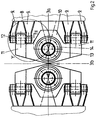
- FIG. 4 shows at the bottom left the radial spherical plain bearing 13 in the swivel bracket 10 with the counter bearings 18 and 20 as well as their fastening elements 19, 21 in the swivel bracket 10 and in the pivot pin 14.
- the wagon body receptacle 11 adjoining the swivel carrier 10 can be seen, by means of which the swivel carrier 10 is articulated on the wagon body brackets 9 in pairs.
- the body pin 12 is mounted in the arms 9 in two bushings 24. This articulation is shown partly in section.
- the bushes 24 consist of an outer tube 24a, which is locked by a press fit in the body booms 8, an inner tube 24b, which is held by a face pressure and an elastic mass located between the two tubes 24a and 24b.
- the bushes 24 can absorb large radial forces on the one hand and have high fatigue strength on the other hand. At the same time, they fulfill the task of being silent and vibration-isolating. In conjunction with the slidable bogie articulation by slide 22 combined with slide 23, this results in an elastic and structure-borne noise-reducing mounting of the car bodies of the end car parts 1, 2.
Abstract
Description
Die Erfindung betrifft eine Verbindungseinrichtung zwischen benachbarten Wagenkästen eines Schienengliederzuges nach dem Oberbegriff des Anspruch 1.The invention relates to a connecting device between adjacent car bodies of a rail articulated train according to the preamble of
Derartige Verbindungseinrichtungen sind aus den Schriften DE-AS 17 55 400, DE-OS 28 26 779 in Verbindung mit DE-OS 38 15 540 sowie DE-OS 39 02 924 bekannt.Such connection devices are known from the documents DE-AS 17 55 400, DE-OS 28 26 779 in connection with DE-OS 38 15 540 and DE-OS 39 02 924.
Die beiden zuerst genannten Schriften beziehen sich jeweils auf eine Verbindungseinrichtung mit einem Knickgelenk über einem gemeinsamen Drehgestell. In den anderen beiden Schriften sind Verbindungseinrichtungen mit niedrig bauenden, bzw. niederflurigen Gelenkverbindungen, die freischwebend angeordnet sind, offenbart.The two first-mentioned documents each relate to a connecting device with an articulated joint above a common bogie. The other two documents disclose connecting devices with low-profile or low-floor articulated connections which are arranged in a free-floating manner.
Diesen in den genannten Schriften offenbarten Verbindungseinrichtungen ist gemeinsam, daß sie einen um eine vertikale Achse drehbaren Roll- oder Drehkranz aufweisen.These connecting devices disclosed in the cited documents have in common that they have a rolling or rotating ring which can be rotated about a vertical axis.
In den beiden älteren Schriften wird angegeben, daß Stützarme der Wagenkästen auf sich ergänzenden Teilen der Kränze aufliegen, wodurch einerseits die Bauhöhe der Gelenkverbindung vergrößert und andererseits eine ungünstige segmentartige Belastung der Ringe des Drehkranzes erzeugt wird. In den beiden jüngeren Schriften ist ein Merkmal, daß die Halterungen der Drehkranzteile, die teilweise biege- und verwindunssteif mit jeweils einem der beiden Fahrzeugteile verbunden sind, in der Höhenebene des Roll- bzw. Drehkranzes liegen. Hiermit wird zwar eine bei Gelenkverbindungen niedrige Bauhöhe erreicht; es bleibt jedoch die bei freischwebenden Gelenken durch Verwindungskräfte im Kranz auftretende Belastung, der durch entsprechende Bauart bzw. Auswahl von ausreichend belastbarem Werkstoff entgegensteuert werden muß.In the two older documents it is stated that support arms of the car bodies rest on complementary parts of the rings, which on the one hand increases the overall height of the articulated connection and on the other hand creates an unfavorable segment-like load on the rings of the slewing ring. In the two more recent documents, it is a feature that the brackets of the slewing ring parts, which are connected to one of the two vehicle parts in each case rigidly and torsionally rigid, lie in the height plane of the rolling or slewing ring. A low overall height is achieved with articulated connections; However, there remains the load occurring in the ring with free-floating joints due to torsional forces, which must be counteracted by appropriate design or selection of sufficiently resilient material.
Gelenkverbindungen von mehrteiligen Schienenzügen mit Roll- bzw. Drehkränzen sind auch deshalb ungünstig, weil ihre Handhabung bei Aus- und Einbau bzw. Reparatur gewichtsbedingt und wegen der großen Bauart umständlich bzw. zeitaufwendig ist.Articulated connections of multi-part rail trains with roller and slewing rings are also unfavorable because their handling during removal and installation or repair is weight-related and because of the large design is cumbersome or time-consuming.
Verbindungseinrichtungen mit freischwebenden Gelenken haben u.a. eine räumliche Trennung von Gelenk und Drehgestell zur Folge. Es ergeben sich dadurch bauliche Schwierigkeiten im Falle einer nachträglichen Verlängerung des Fahrzeuges, z.B. durch Einfügen eines zusätzlichen Mittelteils zwischen zwei Endwagenteilen. Darüber hinaus entstehen bei dieser Lösung ungleiche Wagenkästen. Neuere Bestrebungen der niederflurige Straßenbahnwagen einsetzenden Betriebe gehen aus Gründen der Rationalisierung dahin, eine Standardisierung bzw. Vereinheitlichung der Fahrzeuge und ihrer Teile einzuführen.Connecting devices with free-floating joints result, among other things, in a spatial separation of the joint and the bogie. This results in structural difficulties in the event of a subsequent extension of the vehicle, for example by inserting an additional middle part between two end car parts. In addition, this solution creates unequal car bodies. For reasons of rationalization, recent efforts by companies using low-floor tram cars are moving towards a standardization or standardization of vehicles and their parts.
Der Erfindung liegt daher die Aufgabe zugrunde, eine Verbindungseinrichtung vorzuschlagen, die zur Vereinheitlichung von Gelenkverbindungen zwischen benachbarten Wagenkästen eines Schienengliederzuges geeignet ist, die einen einfachen Aufbau hat und die an die baukastenartige Bauweise von Straßenbahnwagen gut anzupassen ist, so daß die Verlängerung der Fahrzeuge durch Einfügen eines weiteren Mittelteils möglich ist.The invention is therefore based on the object of proposing a connecting device which is suitable for unifying articulated connections between adjacent car bodies of a rail articulated train, which has a simple structure and which can be adapted well to the modular design of tram cars, so that the vehicles can be extended by insertion another middle section is possible.
Diese Aufgabe wird durch eine Verbindungseinrichtung mit den Merkmalen des Anspruchs 1 gelöst. Vorteilhafte Ausgestaltungen der Erfindung sind in den Unteransprüchen angegeben.This object is achieved by a connecting device with the features of
Die mit der Erfindung erzielbaren Vorteile bestehen insbesondere darin, daß es sich um eine für alle Fahrzeuggrößenklassen einsetzbare lösbare Verbindungseinrichtung mit niedriger Gesamtbauhöhe der Gelenkverbindung handelt, die mit bzw. auf einem Drehgestell montiert werden kann. Die Montage ist wegen des einfachen Aufbaus der Gelenkverbindung leicht zu bewerkstelligen.The advantages that can be achieved with the invention are, in particular, that it is a releasable connecting device that can be used for all vehicle size classes and has a low overall height of the articulated connection, which can be mounted with or on a bogie. The assembly is easy to do because of the simple structure of the articulated connection.
Die gesamte Konstruktion kann teilweise Bauelemente oder Abänderungen von Teilen aus bereits bestehenden Verbindungseinrichtungen beinhalten, was somit vereinfachend und kostengünstig wirkt.The entire construction can partially contain components or modifications of parts from already existing connecting devices, which thus has a simplifying and cost-effective effect.
Für das Radial-Gelenklager und die Buchsen der Wagenkastenbolzen können Standardteile entsprechender Hersteller verwendet werden.Standard parts from corresponding manufacturers can be used for the radial spherical plain bearing and the bushings of the body bolts.
Aufgrund der kugeligen Ausgestaltung des Radial-Gelenklagers, die für beide Lagerteile, was ihre kugelige Form betrifft, leicht unterschiedlich ist, eignen sich die erfindungsgemäß vorgeschlagenen Lager für den hier vorliegenden Anwendungsfall besonders gut, weil sie oszillierende Schwenkbewegungen bei relativ niedrigen Gleitgeschwindigkeiten aufnehmen und räumliche Einstellbewegungen zwischen Drehzapfen und Schwenkträger ermöglichen. U.a. hat das Drehgestell die Möglichkeit sich bei Kuppen- bzw. Mulden- und Kurvenfahrt in die winkelhalbierende Lage zu stellen, wodurch der Radreifenverschleiß günstig beeinflußt wird.Due to the spherical design of the radial spherical plain bearing, which is slightly different for both bearing parts as far as their spherical shape is concerned, the bearings proposed according to the invention are particularly suitable for the present application because they absorb oscillating pivoting movements at relatively low sliding speeds and spatial adjustment movements between pivot and swivel bracket. Among other things the bogie has the possibility to position itself in the bisecting position when driving on crests, hollows and bends, which has a favorable influence on tire wear.
Aus dem Zusammenwirken der Gleitstücke und der Gleitbahnen zwischen Wagenkastenaufnahme und Drehgestell ergibt sich eine Drehhemmung, die im normalen Betrieb zur Laufberuhigung des gesamten Fahrverhaltens beiträgt.The interaction of the sliders and the slideways between the body and the bogie results in an anti-rotation feature which, in normal operation, contributes to smoothing the overall driving behavior.
Für den Betreiber von Straßenbahnen sowie Stadtbahnen für die die erfindungsgemäße Verbindungseinrichtung insbesondere verwendet werden kann, bedeutet deren Einsatz aufgrund des einfachen Aufbaus und der Verwendung konventioneller Bauteile und Materialien einen geringen Wartungs- und Instandhaltungsaufwand.For the operator of trams and light rail vehicles for which the connecting device according to the invention can be used in particular, the simple construction and use of conventional components and materials mean that they require little maintenance.
Ein Ausführungsbeispiel der Erfindung wird nachstehend unter Bezugnahme auf der Zeichnung näher beschrieben.An embodiment of the invention is described below with reference to the drawing.
Es zeigen:
- Fig. 1
- eine schematische Übersichtszeichnung einer niederflurigen Straßenbahn mit erfindungsgemäßer Verbindungseinrichtung;
- Fig. 2
- eine Draufsicht gemäß Ausschnitt I-I in Fig. 1;
- Fig. 3
- eine Seitenansicht vom Schnitt II-II in Fig. 2;
- Fig. 4
- eine Draufsicht gemäß Ausschnitt Y in Fig. 2.
- Fig. 1
- a schematic overview drawing of a low-floor tram with connecting device according to the invention;
- Fig. 2
- a plan view according to section II in Fig. 1;
- Fig. 3
- a side view of section II-II in Fig. 2;
- Fig. 4
- 3 shows a plan view according to section Y in FIG. 2.
Fig. 1 zeigt eine erfindungsgemäße Verbindungseinrichtung am Beispiel eines modernen niederflurigen Straßenbahnfahrzeuges mit zwei Endwagenteilen 1, 2. Außer der niederflurigen Gelenkverbindung 3, die sich über den beiden Endwagenteilen 1, 2 gemeinsamen Drehgestell 4a befindet, sind Stabilisator oder hydraulischer Dämpfer 5 am Dach der beiden Wagenteile 1, 2 und eine Übergangseinrichtung mit einem Außenbalg, aufgeteilt in zwei Teile 6a und 6b, abgebildet. Der Außenbalg 6a, 6b ist seitlich dem Verlauf des Drehgestells 4a und des Mittenportals 7 angepaßt, an denen er neben den Endwagenteilen 1, 2 auch befestigt ist.Fig. 1 shows a connecting device according to the invention using the example of a modern low-floor tram vehicle with two
Fig. 2 zeigt die niederflurige Gelenkverbindung 3 in vergrößerter Darstellung von oben. Die Darstellung ist symmetrisch in Bezug auf Längs- und Querachse 3a, 3b der Gelenkverbindung.Fig. 2 shows the low-
Von den an der rechten und linken Außenseite der Zeichnung dargestellten Wagenkastenendquerträgern 8 stehen die Wagenkastenausleger 9 jeweils paarig zur Mitte der Gelenkverbindung 3 vor. Zwischen jedem Paar von Wagenkastenauslegern 9 befindet sich eine Anlenkung des Schwenkträgers 10, der mit an seinen beiden Außenseiten angebrachten Wagenkastenaufnahmen 11 zwischen jeweils ein Paar von Wagenkastenauslegern 9 greift und mit diesen durch einen Wagenkastenbolzen 12 beweglich verbunden ist. Die Wagenkastenausleger 9 eines Wagenkastenendquerträgers 8 sind in einer Höhe angebracht, so daß der Schwenkträger 10 senkrecht zur Fabrzeugebene schwenkbar ist. Im Schwenkträger 10 liegt in der Fahrzeuglängsachse, die mit der Längsachse der 3a der Gelenkverbindung 3 zusammenfällt, das Radial-Gelenklager 13, das in seiner Mitte den Drehzapfen 14 aufnimmt.From the car body
Die in Fig. 3 vergrößert abgebildete Schnittdarstellung aus Fig. 2 zeigt einerseits den Zusammenbau von Radial-Gelenklager 13 mit dem Drehzapfen 14 und andererseits eine Seitenansicht der Verbindung von Schwenkträger 10 bzw. Wagenkastenaufnahme 11 mit Wagenkastenbolzen 12 am Wagenkastenausleger 9 über der gleitfähigen Drehstellanlenkung.The enlarged representation shown in FIG. 3 from FIG. 2 shows on the one hand the assembly of the radial spherical plain bearing 13 with the
Der Drehzapfen 14 ist mit seinem Flansch 14a mit lösbaren Befestigungselementen 15, z.B. mit Innensechskantschrauben, an der Drehgestellwiege 16, in die er durch eine Bohrung 16a von unten hindurchgesteckt wird, befestigt.The
Über dem Drehzapfen 14 auf der Drehgestellwiege 16 sitzt ein Distanzring 17, mit dem im Bedarfsfall durch eine spanende Bearbeitung eine Niveauregulierung des sich auf dem Distanzring 17 abstützenden Radial-Gelenklagers 13 vorgenommen werden kann. Das Radial-Gelenklager 13 besteht aus einem Außenring 13 a, der geteilt sein kann, mit hohlkugeliger Innenform und einem Innenring 13b mit kugeliger Außenform. Der Außenring 13a ist mit einem Gegenlager 18 mittels lösbarer Befestigungselemente 19, wie z.B. Sechskantschrauben, an dem Schwenkträger 10 und der Innenring 13b mit einem Gegenlager 20 mittels lösbarer Befestigungselemente 21 an dem Drehzapfen 14 axial verspannt.Above the
Durch die bauchige bzw. hohlkugelförmige Ausgestaltung von Außen- und Innenring 13a, 13b des Radial-Gelenklagers 13, die jeweils mit Preßsitz montiert sind, wird der Schwenkträger 10 in einer solchen Lage zum Drehzapfen 14 gehalten, daß zwischen beiden Bauteilen 10, 14 außer der Drehbewegung auch gleichzeitig in gewissen Grenzen eine Neigung einstellbar ist, wie sie beispielsweise bei Kippen- oder Muldenfahrt durch die Nickbewegung des Schwenkträgers 10 auftritt.Due to the bulbous or hollow spherical design of the outer and
In der Seitenansicht der Befestigung von Schwenkträger 10 bzw. Wagenkastenaufnahme 11 mit Wagenkastenbolzen 12 an den Wagenkastenauslegern 9 ist dargestellt, daß unter der Wagenkastenaufnahme 11 ein Gleitstück 22 montiert ist, womit sich die Wagenkastenaufnahme 11 über eine Gleitbahn 23 auf der Drehgestellwiege 16 abstützt. Auf diese Weise ist eine aus Kurvenfahrten resultierende Querverschiebung zwischen den Wagenkästen der Endwagenteile 1, 2 einerseits und dem Drehgestell 4a andererseits nach Maßgabe der Gleitbahn 23 glich.In the side view of the attachment of the
Die in Fig. 4 dargestellte Draufsicht zeigt unten links das Radial-Gelenklager 13 im Schwenkträger 10 mit den Gegenlagern 18 und 20 sowie deren Befestigungselemente 19, 21 im Schwenkträger 10 und im Drehzapfen 14.The top view shown in FIG. 4 shows at the bottom left the radial spherical plain bearing 13 in the
Im oberen Bildteil von Fig. 4 ist die am Schwenkträger 10 anschließende Wagenkastenaufnahme 11 erkenntlich, mit der der Schwenkträger 10 an den paarweise vorhandenen Wagenkastenauslegern 9 beweglich angelenkt ist. Der Wagenkastenbolzen 12 ist in den Auslegern 9 in zwei Buchsen 24 gelagert. Diese Anlenkung ist teilweise geschnitten dargestellt. Die Buchsen 24 bestehen aus einem Außenrohr 24a, das durch Preßsitz in den Wagenkastenauslegern 8 arretiert ist, einem Innenrohr 24b, das durch eine Stirnflächenpressung gehalten wird und einer zwischen beiden Rohren 24a und 24b befindlichen elastischen Masse. Die Buchsen 24 können einerseits große Radialkräfte aufnehmen und verfügen andererseits über eine hohe Dauerfestigkeit. Sie erfüllen gleichzeitig die Aufgabe geräuschlos und schwingungsisolierend zu funktionieren. In Verbindung mit der gleitfähigen Drehgestellanlenkung durch Gleitstück 22 kombiniert mit Gleitbann 23 erfolgt hiermit eine elastische und körperschallreduzierende Lagerung der Wagenkästen der Endwagenteile 1, 2.In the upper part of FIG. 4, the
Am Wagenkastenbolzen 12 wird auf der einen Seite durch das Gegenlager 12a und auf der anderen Seite durch eine im Bolzen 12 zu befestigende Schraube 25 mit Unterlegscheibe 26 Stirnflächenpressung bewirkt.On the
- 11
- - Endwagenteil links- Left end section
- 22nd
- - Endwagenteil rechts- Right end section
- 33rd
- - niederflurige Gelenkverbindung- low-floor articulation
- 3a3a
- - Längsachse der niederflurigen Gelenkverbindung- Longitudinal axis of the low-floor articulation
- 3b3b
- - Querachse der niederflurigen Gelenkverbindung- Transverse axis of the low-floor articulation
- 44th
- - Drehgestell- bogie
- 4a4a
- - Drehgestell unterhalb der niederflurigen Gelenkverbindung zwischen den Endwagenteilen- Bogie below the low-floor articulation between the end car parts
- 55
- - Stabilisator oder hydraulischer Dämpfer- Stabilizer or hydraulic damper
- 6a6a
- - Faltenbalg links- Bellows on the left
- 6b6b
- - Faltenbalg rechts- Bellows on the right
- 77
- - Mittenportal- Center portal
- 88th
- - Wagenkastenendquerträger- Carriage end cross member
- 99
- - Wagenkastenausleger- body boom
- 1010th
- - Schwenkträger- swivel bracket
- 1111
- - Wagenkastenaufnahme- Car body holder
- 1212th
- - Wagenkastenbolzen- body bolts
- 12a12a
- - Gegenlager des Wagenkastenbolzens- Counter bearing of the body bolt
- 1313
- - Radial-Gelenklager- Radial spherical plain bearings
- 13a13a
- - Außenring Radial-Gelenklager- Outer ring radial spherical plain bearing
- 13b13b
- - Innenring Radial-Gelenklager- Inner ring radial spherical plain bearing
- 1414
- - Drehzapfen- pivot
- 14a14a
- - Flansch des Drehzapfens- Flange of the pivot
- 1515
- - lösbares Befestigungselement (Innensechskantschraube)- detachable fastening element (hexagon socket screw)
- 1616
- - Drehgestellwiege- bogie cradle
- 16a16a
- - Bohrung für Drehzapfen in der Drehgestellwiege- Hole for pivot in the bogie cradle
- 1717th
- - Distanzring- Spacer ring
- 1818th
- - Gegenlager Außenring Radial-Gelenklager- Counter bearing outer ring radial spherical plain bearing
- 1919th
- - lösbares Befestigungselement (Sechskantschraube)- detachable fastening element (hexagon screw)
- 2020th
- - Gegenlager Innenring Radial-Gelenklager- Counter bearing inner ring radial spherical plain bearing
- 2121
- - lösbares Befestigungselement (Sechskantschraube)- detachable fastening element (hexagon screw)
- 2222
- - Gleitstück- slider
- 2323
- - Gleitbahn- slideway
- 2424th
- - Buchse- Rifle
- 24a24a
- - Außenrohr der Buchse- outer tube of the socket
- 24b24b
- - Innenrohr der Buchse- Inner tube of the socket
- 2525th
- - lösbares Befestigungselement (Sechskantschraube)- detachable fastening element (hexagon screw)
- 2626
- - Unterlegscheibe- washer
- 2727
- - Distanzscheibe- spacer
Claims (3)
Applications Claiming Priority (2)
| Application Number | Priority Date | Filing Date | Title |
|---|---|---|---|
| DE4422581 | 1994-06-28 | ||
| DE4422581A DE4422581A1 (en) | 1994-06-28 | 1994-06-28 | Connecting device between adjacent car bodies of a rail articulated train, in particular between low-floor tram cars |
Publications (2)
| Publication Number | Publication Date |
|---|---|
| EP0689980A1 true EP0689980A1 (en) | 1996-01-03 |
| EP0689980B1 EP0689980B1 (en) | 1999-10-13 |
Family
ID=6521696
Family Applications (1)
| Application Number | Title | Priority Date | Filing Date |
|---|---|---|---|
| EP95107309A Expired - Lifetime EP0689980B1 (en) | 1994-06-28 | 1995-05-15 | Connection device between adjacent vehicle bodies of an articulated railway train, especially between low floor tramway vehicles |
Country Status (5)
| Country | Link |
|---|---|
| EP (1) | EP0689980B1 (en) |
| AT (1) | ATE185529T1 (en) |
| DE (2) | DE4422581A1 (en) |
| ES (1) | ES2137400T3 (en) |
| NO (1) | NO303276B1 (en) |
Cited By (2)
| Publication number | Priority date | Publication date | Assignee | Title |
|---|---|---|---|---|
| EP1048544A1 (en) * | 1999-04-29 | 2000-11-02 | ALSTOM LHB GmbH | Articulated link for vehicle units of railway vehicles |
| CN111661093A (en) * | 2020-06-18 | 2020-09-15 | 中车大连机车车辆有限公司 | Articulated bogie of railway vehicle |
Families Citing this family (4)
| Publication number | Priority date | Publication date | Assignee | Title |
|---|---|---|---|---|
| DE19749507B4 (en) * | 1997-11-08 | 2005-07-28 | Db Reise & Touristik Ag | Connecting vehicle bodies |
| DE19819927C2 (en) * | 1998-05-05 | 2003-04-17 | Siemens Ag | Device for the articulated connection of adjacent car bodies of a rail vehicle, in particular for local traffic |
| DE102019211074A1 (en) * | 2019-07-25 | 2021-01-28 | Siemens Mobility GmbH | Rail vehicle with a force-applying arrangement |
| DE102021203059A1 (en) | 2021-03-26 | 2022-09-29 | Siemens Mobility GmbH | Rail vehicle with connecting device |
Citations (7)
| Publication number | Priority date | Publication date | Assignee | Title |
|---|---|---|---|---|
| DE1755400A1 (en) | 1968-05-04 | 1971-09-30 | Linke Hofmann Busch | Articulated connection device between the car bodies of a smooth-running train |
| FR2348092A1 (en) * | 1976-04-16 | 1977-11-10 | Mte | Pivot between railway vehicle bodies - has vertical pivot in two rings, one on wheeled support and other on joints round horizontal axis |
| DE2826779A1 (en) | 1978-06-19 | 1980-01-03 | Linke Hofmann Busch | Wagon coupling for railway train - has pivot pin below bar on rotating plate through bellows onto bogie |
| DE3815540A1 (en) | 1988-05-06 | 1989-11-16 | Waggon Union Gmbh | JOINT CONNECTION |
| DE3902924A1 (en) | 1989-02-01 | 1990-08-02 | Duewag Ag | DEVICE FOR JOINTLY CONNECTING THE CAR BODIES OF A VEHICLE, IN PARTICULAR A RAIL VEHICLE |
| US5207161A (en) * | 1992-07-24 | 1993-05-04 | Gunderson, Inc. | Side bearing arrangement for multi-unit railroad cars with different side bearings on adjacent car ends sharing a common truck |
| EP0567950A1 (en) * | 1992-04-28 | 1993-11-03 | AEG Schienenfahrzeuge GmbH | Railway vehicle |
Family Cites Families (8)
| Publication number | Priority date | Publication date | Assignee | Title |
|---|---|---|---|---|
| DE1987153U (en) * | 1968-06-12 | Waggonfabrik Joset Rathgeber A G , 8000 München | Ghe the rail vehicle | |
| DE1605188B2 (en) * | 1967-05-30 | 1973-08-09 | Moskowskij Ordena Lenina I Ordena Trudowowo Krasnowo Snameni Institut Inschenerow Schelesnodoroschnowo Transporta, Moskau | COUPLING DEVICE FOR THE ENDS OF TWO CONNECTED VEHICLE UNITS OF A RAIL-MOUNTED ARTICULATED VEHICLE |
| FR1594322A (en) * | 1968-05-10 | 1970-06-01 | ||
| DE2440069C3 (en) * | 1974-08-21 | 1979-06-07 | Hamburger Hochbahn Ag, 2000 Hamburg | Bogie for the joint articulated support of two car bodies |
| IT1193140B (en) * | 1983-07-29 | 1988-06-02 | Fiat Ferroviaria Savigliano | INTERCOMMUNICATION PASSAGE BETWEEN THE TWO BODYWORKS OF A RAILWAY VEHICLE AND A RAILWAY VEHICLE USING SUCH INTERCOMMUNICATION PASSAGE |
| CA1337027C (en) * | 1984-12-04 | 1995-09-19 | Harry O. Wicks | Railway highway vehicle |
| DE3924642A1 (en) * | 1988-09-20 | 1990-03-22 | Diekmann Gmbh A | Passenger train in mine - has ends of adjacent vehicles supported on common bogie |
| DE9209966U1 (en) * | 1992-07-24 | 1993-11-25 | Linke Hofmann Busch | Track-guided vehicle group consisting of at least two vehicles with controlled single wheel set bogies |
-
1994
- 1994-06-28 DE DE4422581A patent/DE4422581A1/en not_active Withdrawn
-
1995
- 1995-05-15 EP EP95107309A patent/EP0689980B1/en not_active Expired - Lifetime
- 1995-05-15 DE DE59507026T patent/DE59507026D1/en not_active Expired - Fee Related
- 1995-05-15 AT AT95107309T patent/ATE185529T1/en not_active IP Right Cessation
- 1995-05-15 ES ES95107309T patent/ES2137400T3/en not_active Expired - Lifetime
- 1995-06-23 NO NO952544A patent/NO303276B1/en unknown
Patent Citations (7)
| Publication number | Priority date | Publication date | Assignee | Title |
|---|---|---|---|---|
| DE1755400A1 (en) | 1968-05-04 | 1971-09-30 | Linke Hofmann Busch | Articulated connection device between the car bodies of a smooth-running train |
| FR2348092A1 (en) * | 1976-04-16 | 1977-11-10 | Mte | Pivot between railway vehicle bodies - has vertical pivot in two rings, one on wheeled support and other on joints round horizontal axis |
| DE2826779A1 (en) | 1978-06-19 | 1980-01-03 | Linke Hofmann Busch | Wagon coupling for railway train - has pivot pin below bar on rotating plate through bellows onto bogie |
| DE3815540A1 (en) | 1988-05-06 | 1989-11-16 | Waggon Union Gmbh | JOINT CONNECTION |
| DE3902924A1 (en) | 1989-02-01 | 1990-08-02 | Duewag Ag | DEVICE FOR JOINTLY CONNECTING THE CAR BODIES OF A VEHICLE, IN PARTICULAR A RAIL VEHICLE |
| EP0567950A1 (en) * | 1992-04-28 | 1993-11-03 | AEG Schienenfahrzeuge GmbH | Railway vehicle |
| US5207161A (en) * | 1992-07-24 | 1993-05-04 | Gunderson, Inc. | Side bearing arrangement for multi-unit railroad cars with different side bearings on adjacent car ends sharing a common truck |
Cited By (3)
| Publication number | Priority date | Publication date | Assignee | Title |
|---|---|---|---|---|
| EP1048544A1 (en) * | 1999-04-29 | 2000-11-02 | ALSTOM LHB GmbH | Articulated link for vehicle units of railway vehicles |
| CN111661093A (en) * | 2020-06-18 | 2020-09-15 | 中车大连机车车辆有限公司 | Articulated bogie of railway vehicle |
| CN111661093B (en) * | 2020-06-18 | 2022-04-05 | 中车大连机车车辆有限公司 | Articulated bogie of railway vehicle |
Also Published As
| Publication number | Publication date |
|---|---|
| NO952544D0 (en) | 1995-06-23 |
| DE4422581A1 (en) | 1996-01-04 |
| NO952544L (en) | 1995-12-29 |
| ATE185529T1 (en) | 1999-10-15 |
| ES2137400T3 (en) | 1999-12-16 |
| DE59507026D1 (en) | 1999-11-18 |
| NO303276B1 (en) | 1998-06-22 |
| EP0689980B1 (en) | 1999-10-13 |
Similar Documents
| Publication | Publication Date | Title |
|---|---|---|
| EP1915283B1 (en) | Vehicle with anti-roll devices | |
| DE1605826C3 (en) | Bogie for railway wagons with at least two wheelsets | |
| EP0565676B1 (en) | Running gear for low-platform waggons | |
| EP0567950B1 (en) | Railway vehicle | |
| WO1990002068A1 (en) | Bogie for high-speed rail vehicles | |
| EP0547188B1 (en) | Bogie for high-speed railway vehicles | |
| CH671930A5 (en) | ||
| DE102008027129B4 (en) | Bogie with two-part frame | |
| EP0689980B1 (en) | Connection device between adjacent vehicle bodies of an articulated railway train, especially between low floor tramway vehicles | |
| EP1897777B1 (en) | Bogie | |
| DE102007027592A1 (en) | Vehicle with articulated car bodies | |
| EP0507146B1 (en) | Railway vehicle especially low floor vehicle | |
| DE10210059C1 (en) | coupling rod | |
| EP1928722B1 (en) | Vehicle comprising a pitch joint | |
| EP0046457B1 (en) | Four-axle bogie for a low-platform railway truck | |
| DE19703701C2 (en) | Two-axle chassis for rail-bound transport systems | |
| EP1897776B1 (en) | Bogie | |
| DE2029329A1 (en) | Axle bearing guide for rail vehicles, in particular for bogie locomotives | |
| DE3221755A1 (en) | Bogie for a rail vehicle | |
| EP0659626A1 (en) | Single running gear for rail vehicles | |
| CH684075A5 (en) | Bogie. | |
| EP2158114B1 (en) | Rail vehicle with single-stage suspension | |
| EP1226058B1 (en) | Bogie for rail vehicles | |
| EP0749882A2 (en) | Suspension device for brake units of railway vehicles | |
| CH392598A (en) | Suspension |
Legal Events
| Date | Code | Title | Description |
|---|---|---|---|
| PUAI | Public reference made under article 153(3) epc to a published international application that has entered the european phase |
Free format text: ORIGINAL CODE: 0009012 |
|
| AK | Designated contracting states |
Kind code of ref document: A1 Designated state(s): AT BE DE ES FR NL SE |
|
| 17P | Request for examination filed |
Effective date: 19960115 |
|
| 17Q | First examination report despatched |
Effective date: 19980312 |
|
| GRAG | Despatch of communication of intention to grant |
Free format text: ORIGINAL CODE: EPIDOS AGRA |
|
| RAP1 | Party data changed (applicant data changed or rights of an application transferred) |
Owner name: ALSTOM LHB GMBH |
|
| GRAG | Despatch of communication of intention to grant |
Free format text: ORIGINAL CODE: EPIDOS AGRA |
|
| GRAH | Despatch of communication of intention to grant a patent |
Free format text: ORIGINAL CODE: EPIDOS IGRA |
|
| GRAH | Despatch of communication of intention to grant a patent |
Free format text: ORIGINAL CODE: EPIDOS IGRA |
|
| GRAA | (expected) grant |
Free format text: ORIGINAL CODE: 0009210 |
|
| AK | Designated contracting states |
Kind code of ref document: B1 Designated state(s): AT BE DE ES FR NL SE |
|
| REF | Corresponds to: |
Ref document number: 185529 Country of ref document: AT Date of ref document: 19991015 Kind code of ref document: T |
|
| REF | Corresponds to: |
Ref document number: 59507026 Country of ref document: DE Date of ref document: 19991118 |
|
| REG | Reference to a national code |
Ref country code: ES Ref legal event code: FG2A Ref document number: 2137400 Country of ref document: ES Kind code of ref document: T3 |
|
| ET | Fr: translation filed | ||
| PLBE | No opposition filed within time limit |
Free format text: ORIGINAL CODE: 0009261 |
|
| STAA | Information on the status of an ep patent application or granted ep patent |
Free format text: STATUS: NO OPPOSITION FILED WITHIN TIME LIMIT |
|
| 26N | No opposition filed | ||
| PGFP | Annual fee paid to national office [announced via postgrant information from national office to epo] |
Ref country code: SE Payment date: 20060512 Year of fee payment: 12 |
|
| PGFP | Annual fee paid to national office [announced via postgrant information from national office to epo] |
Ref country code: NL Payment date: 20060515 Year of fee payment: 12 Ref country code: AT Payment date: 20060515 Year of fee payment: 12 |
|
| PGFP | Annual fee paid to national office [announced via postgrant information from national office to epo] |
Ref country code: FR Payment date: 20060519 Year of fee payment: 12 Ref country code: DE Payment date: 20060519 Year of fee payment: 12 |
|
| PGFP | Annual fee paid to national office [announced via postgrant information from national office to epo] |
Ref country code: ES Payment date: 20060530 Year of fee payment: 12 |
|
| PGFP | Annual fee paid to national office [announced via postgrant information from national office to epo] |
Ref country code: BE Payment date: 20060616 Year of fee payment: 12 |
|
| BERE | Be: lapsed |
Owner name: *ALSTOM LHB G.M.B.H. Effective date: 20070531 |
|
| EUG | Se: european patent has lapsed | ||
| PG25 | Lapsed in a contracting state [announced via postgrant information from national office to epo] |
Ref country code: NL Free format text: LAPSE BECAUSE OF NON-PAYMENT OF DUE FEES Effective date: 20071201 |
|
| NLV4 | Nl: lapsed or anulled due to non-payment of the annual fee |
Effective date: 20071201 |
|
| PG25 | Lapsed in a contracting state [announced via postgrant information from national office to epo] |
Ref country code: AT Free format text: LAPSE BECAUSE OF NON-PAYMENT OF DUE FEES Effective date: 20070515 |
|
| REG | Reference to a national code |
Ref country code: FR Ref legal event code: ST Effective date: 20080131 |
|
| PG25 | Lapsed in a contracting state [announced via postgrant information from national office to epo] |
Ref country code: BE Free format text: LAPSE BECAUSE OF NON-PAYMENT OF DUE FEES Effective date: 20070531 |
|
| PG25 | Lapsed in a contracting state [announced via postgrant information from national office to epo] |
Ref country code: DE Free format text: LAPSE BECAUSE OF NON-PAYMENT OF DUE FEES Effective date: 20071201 |
|
| PG25 | Lapsed in a contracting state [announced via postgrant information from national office to epo] |
Ref country code: SE Free format text: LAPSE BECAUSE OF NON-PAYMENT OF DUE FEES Effective date: 20070516 |
|
| PG25 | Lapsed in a contracting state [announced via postgrant information from national office to epo] |
Ref country code: FR Free format text: LAPSE BECAUSE OF NON-PAYMENT OF DUE FEES Effective date: 20070531 |
|
| REG | Reference to a national code |
Ref country code: ES Ref legal event code: FD2A Effective date: 20070516 |
|
| PG25 | Lapsed in a contracting state [announced via postgrant information from national office to epo] |
Ref country code: ES Free format text: LAPSE BECAUSE OF NON-PAYMENT OF DUE FEES Effective date: 20070516 |