FIELD OF THE INVENTION
The present invention relates generally to the development of an object-oriented
application program within a computer system. More specifically, the present invention
relates to processing and filtering the features of an object interface to facilitate the
development of an object-oriented application program within a distributed object system.
BACKGROUND OF THE INVENTION
With the increasing popularity and importance of object-oriented systems and
applications, it has become critical to be able to develop applications in an efficient and
reliable manner. Especially within the context of a distributed object system where objects
may be more complex and may reside in remote locations, it can be very time consuming
for an application developer not only to write the code to implement a local object, but also
to locate a remote object and determine what information he or she either needs from the
remote object or must provide to the remote object. In general, traditional notions of
efficient coding and reuse of software code are equally applicable in regard to the
development of application programs for distributed object systems.
Due to the nature of object-oriented programming within a distributed object system,
an application developer is constantly defining new objects, invoking methods on already
existing remote objects or receiving information from a remote object for use by previously
defined local objects. Accordingly, techniques that would allow an application developer to
reuse existing objects in the formation of new objects and implementations would save the
developer from having to write these objects from scratch. Also, an apparatus that would
allow an application developer to be able to locate objects in a distributed environment to be
used within a new application program would be helpful. However, once an existing
object has been located within a distributed object environment and has been identified for
reuse, it is important to determine what services the object provides and what services it
requires in order to connect this object to other objects so as to form a new implementation
i.e., the services that one object provides may be used by another object. But first, the
services that an object provides and requires are be determined so that a developer can make
intelligent choices about how an object may be connected to other objects.
Accordingly, it would be desirable to have a technique and apparatus for determining
what services are needed by an object and what services are provided by an object.
Furthermore, it would be desirable to be able to filter the definition of an object in the
context of a visual tool such that this information may be displayed visually to the user.
Additionally, it would be desirable for such a technique to assist in making the connections
between objects such that services may be made available to objects requiring them.
SUMMARY OF THE INVENTION
In one aspect of the present invention, the filtering technique takes place within a
distributed object application builder apparatus. Each part (representing a run-time instance
of an object) in the builder has plugs and sockets that are interconnected to other parts in
order to define distributed object application programs. Each part corresponds to a
component, which in turn, represents a distributed object. One method of determining the
plugs of an identified part includes the step ofretrieving the interface for the component that
corresponds to the part. Once this interface has been retrieved, the plugs of the part may be
identified. The plugs are identified by determining attributes from the retrieved interface,
by determining operations from the retrieved interface that require one operation argument,
and by retrieving the factory argument list from the factory method for the object that is
represented by the component. These attributes and arguments are the plugs of the part.
Also, the sockets of a part may be determined by using a similar method. A method
of determining the sockets of an identified part includes the step of retrieving the interface
for the component that corresponds to the part. Once this interface has been retrieved, the
sockets of the part may be identified. The sockets are identified by determining attributes
from the retrieved interface and by determining operations from the retrieved interface that
returns an object result.n These attributes and operations constitute the sockets of the part.
In another aspect of the invention, the plugs of a part may be determined based upon
their matching with a previously chosen socket. In this method, a second part is identified
and a socket of this second part is chosen. Next, it is determined whether the chosen
socket of the second part is compatible with a determined plug of said first part and
indicating this match. The chosen socket is compatible with a plug of the original part if
the type of the plug is a CORBA object, is the same as the socket type, or if the plug type is
any type from which the socket inherits. Similarly, if a plug is chosen first from a part,
this chosen plug may match with a socket of another part if the type of the socket is the
same as, or inherits from the plug type. In this embodiment, the sockets may be
determined in a recursive manner using "tunneling".
A distributed object application program may be constructed in one embodiment by
choosing a first component from the component catalog. Once chosen, a first part
corresponding to this first component is created in the composition builder. Next, a first
interface for this first component is retrieved. The filtering technique as described in the
present invention is then used to filter this first interface in order to produce a list of the
plugs and sockets for the first part. Once this first interface is filtered, the procedure may
be repeated for a second, or any number of other components. Once plugs and sockets of
various parts have been determined, they may be connected in order to at least partially
define a distributed object application program. And when the program executes, the parts
are arranged to pass references to one according to these connections.
Additionally, in a further embodiment of the invention the filtering may take place
within a visual application builder using a graphical user interface in which the plugs and
sockets are represented symbolically by icons for each part. Connections may be formed
by selecting an icon or part with a gesture and then using a visual inspector to choose a
particular plug or socket to make the connection. These connections may be represented
visually in a composition worksheet of the visual builder.
BRIEF DESCRIPTION OF THE DRAWINGS
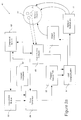
FIGURE 1 is an overview of an object request broker of a distributed object system
in accordance with one embodiment of the present invention.
FIGURE 2 is a block diagram of the visual application builder that is shown in
Figure 1 according to one embodiment of the present invention.
FIGURE 2a illustrates schematically the visual application builder of Figure 2 in
more detail for use in composing object-oriented applications in a distributed object system.
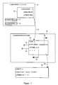
FIGURE 3 shows the relationship between the component catalog, the composition
builder and a run-time object in the context of the visual application builder, according to
one embodiment of the present invention.
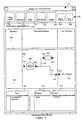
FIGURE 4 is a view of the composition builder in which the inspector is being
used to set a property value, according to one embodiment of the present invention.
FIGURE 5 is a view of the composition builder in which the inspector is being
used to connect a plug to a socket, according to one embodiment of the present invention.
FIGURE 6 is a flow chart for determining all of the plugs for a given part in the
composition builder, according to one embodiment of the present invention.
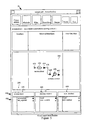
FIGURE 7 is a flow chart for determining all of the available matching plugs of a
given part for a particular socket, according to one embodiment of the present invention.
FIGURE 8 is a flow chart for determining a socket of a part to be used for a
connection to another part, according to one embodiment of the present invention.
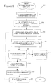
FIGURE 9 is a flow chart for determining a matching socket of a part for a
connection to a given plug, according to one embodiment of the present invention.
FIGURE 10 is a typical computer system for implementing the present invention.
DETAILED DESCRIPTION OF THE INVENTION
OVERVIEW
The present invention is directed toward distributed object systems and will be
described with reference to several preferred embodiments as illustrated in the
accompanying drawings. The invention may be practiced within the context of any suitable
distributed object system, including those defined under CORBA or any other suitable
specification. However, for purposes of illustration, an embodiment of the present
invention will be described primarily within the context of an Object Request Broker (ORB)
implemented under the CORBA specification from the Object Management Group (OMG),
Revision 2.0, dated July 1995. Figure 1 diagrammatically illustrates the overall
architecture of a representative distributed object system suitable for implementing an
embodiment of the present invention.
A distributed object system 10 typically includes an Object Request Broker (ORB) 11
as is symbolically illustrated in Figure 1. ORB 11 provides all of the location and transport
mechanisms and facilities necessary to deliver a call from a client to a servant (target
object) and to return a response to the client. The client and servant may be located in the
same process, in different processes on the same machine, or on completely different
machines. For the purposes of this discussion, client 20 may be any code that invokes an
operation on a distributed object and thus may or may not take the form of a distributed
object or a process. A distributed object may have a wide variety of representations. By
way of example, the distributed object may be a C++ object that has been provided by an
application developer. Alternatively, an implementation for a distributed object may be
developed within a visual application builder 15. This visual application builder allows a
developer to visually select existing object types from a catalog and graphically connect the
services provided by one object to the services needed by another (attributes, arguments.
results etc.) in order to create a new implementation for an object.
An object development facility 16 may be used to simplify the creation and the
installation of distributed objects. It is used to "wrap" or encapsulate developer objects in
distributed object code. As such, object development facility 16 may be used to transform
a developer object into an ORB object implementation 14. In this example, ORB object
implementation 14 is presented as a server as shown by its location in the diagram. A
developer uses an interface definition language to define an interface for an ORB object,
provides a developer object implementation that implements that object's behavior, and then
uses the object development facility 16 in order to produce an ORB object implementation
14. At run time, an instance of this ORB object (a servant object) is created that will utilize
this ORB object implementation 14. It should be appreciated that the object development
facility may also be used to create objects that take the role of clients at some point.
Client 20 communicates with a servant by way of a stub 21, a subcontract layer 36,
possibly a filter 40, and a transport layer 38. Stub 21 includes a surrogate 22, a method
table 24 and stub functions 25. Client 20 communicates initially with surrogate 22 that
appears to the client as the servant object. Alternatively, client 20 may communicate
directly with the servant object through a dynamic invocation interface (DII) 26 instead of
through surrogate 22, method table 24 and stub functions 25. Dynamic invocation
interface 26 is used to enable clients to construct dynamic requests.
Subcontract layer 36 provides the functionality required by an object in order to
utilize subcontracts to implement various services (or features or object mechanisms)
named by a particular subcontract. A subcontract identifies a quality of service provided by
the distributed object system that may be utilized by an individual object. For example, a
subcontract may identify that the feature of security is to be used for a particular object. A
particular subcontract may be associated dynamically at run time with a servant object.
Filter 40, if being used, may perform a variety of tasks, such as compression, encryption,
tracing, or debugging, that are to be applied to communications to and from an object.
Transport layer 38 operates to marshal, unmarshal and physically transport information to
and from a servant that typically does not share the same process as a client.
A standard implementation suite 28 (or object adapter) represents a set of
subcontracts that interact with ORB objects 14 in identical ways, as in object key
management. A subcontract may also belong to multiple implementation suites. Also,
implementation suites may utilize different subcontracts. A skeleton (in the form of either
static skeleton 32 or dynamic skeleton 30) is used to transform requests into a format
required by a servant object. Thus, skeletons 30 and 32 call an appropriate servant object.
Static skeleton 32 is used to call interface-specific object implementations 14, while
dynamic skeleton 30 is used generically when interface-specific objects are not available.
An ORB interface 34 is the interface that goes directly to the ORB that is the same for all
ORBs and does not depend upon an object's interface or object adapter. An ORB daemon
46 is responsible for ensuring that object servers are active when invoked by clients.
Secure Protocol 42 is a secure interoperability protocol that secures the intemet inter-ORB
protocol and helps to transmit information through transport layer 38 in a secure
fashion. This may mean integrity protection, confidentiality, etc. The intemet inter-ORB
protocol is a protocol that typically communicates between processes on different
machines. However, in some cases, the intemet inter-ORB protocol may communicate
between processes on the same machine. Security server 54 is a security administration
server that secures the services that are used between processes on different computers.
Typecode/Any module 44 implements "Typecode" and "Any" objects. Typecode
describes an Interface Definition Language (IDL) data type, allowing type descriptions to
be transmitted between clients and servers. An instance of an IDL data type may be
encapsulated by an Any object. An Any object refers to typecode of the encapsulated data,
and a generic encoding of the data.
An implementation repository 50 is used to store information relating to object
servers. Specifically, implementation repository 50 stores the information needed to start a
server process. For example, implementation repository 50 stores information such as the
location of the server program, any arguments to the program, and any environment
variables to pass to the program, etc.
Simple persistence 56 uses an Interface Definition Language (IDL)-defined type and
the output from running that IDL type through the IDL compiler, together with a portion of
additional code so that an IDL-defined type can be read from, and written to, disk. A
naming service 52 is used to name ORB objects. A client may use naming service 52 to
find a desired object by name. Naming service 52 returns an object reference, that in turn
may be used to send requests to that object. An Interface Repository 48 (IFR) knows
about all interfaces for all objects within the distributed object system.
DESCRIPTION OF THE PREFERRED EMBODIMENTS
An embodiment of the present invention relates to a technique for filtering the
definition of an object for use within an application builder. By use of this technique, the
services that an object (either local or remote) needs or provides in order to function as a
piece of an application program may be determined and used by an application developer.
The benefits include reusability of objects, quicker build time, and an easier build within
the context of a visual application builder. As referred to herein, the term "object" may
mean the object definition, associated operations, attributes, etc., and implementation for
that object. As will be appreciated by those of skill in the art, at times the term "object
type" is used to refer to the definition of the operations and attributes that software external
to the object may use to examine and operate upon the object. The "object type" is also
know as the "interface". Also, the term "object" may be used to refer to an actual run-time
instance of an object and will be made clear by the context.
As discussed above, it would be desirable to have a technique and apparatus that
would allow an application developer to reuse existing objects and that would allow a
developer to be able to locate objects in a distributed environment to be used within a new
application program. By way of example, one such technique and apparatus, is called a
"Visual Application Builder".
The Visual Application Builder allows an application developer to visually construct
an application program using distributed objects. A catalog of existing and previously
defined objects is provided so that the developer may easily identify and retrieve remote
objects for use in developing new software applications. Additionally, these objects may
be reused within the Builder when forming new objects, thus permitting the reuse of code.
When an object is selected for use within the Builder it may provide certain services or it
may require services for its own use. By way of example, an object may have attributes
that may take values, and may have operations (or methods) that require arguments and
return results. Services required by an object may be values for its attributes and argument
values for its operations. Likewise, services provided by an object may be its attributes
that already have values and the results of operations. When building an application,
services supplied by one object may be "connected" or delivered to an object that needs
those services for processing. For example, the value of an attribute for one object may be
used as an argument for an operation of another object. It is important for the purpose of
connecting objects to be able to determine which services are provided by a given object
and which services are needed by a given object. A technique and apparatus for
performing such functions is the subject of the present invention and is described below.
In an embodiment of the present invention, the terms Component, Part, Plugs and
Sockets have the following meanings. A Component represents an object (or object type),
the service it provides, its implementation, and its name in the distributed object system
naming service. Components are present in a component catalog from which a user can
examine and choose components to be applied to the application being built. When the user
adds a component to the application under construction, a builder mechanism derives a part
using the information contained in the component using the methods and mechanisms
described herein. A part is a place holder for a future run-time instance of the object
represented by the component, and may be treated as the run-time instance for the purposes
of establishing connections with other objects and defining property values. When the
completed application is processed by the builder, code is generated to represent the part
and the actions it performs in relation to other objects in the application. The representation
of the part is a place holder for a run-time instance of the object. Thus, when the
application finally runs, a run-time instance of the object will be located or created and
substituted for the part.
In one embodiment, each part has Plugs and Sockets that may be represented visually
by a single plug icon or socket icon respectively. As described above, an object may
require values for its attributes and argument values for its operations. A Plug is used to
represent such needed services by an object. Other services may also be represented by a
plug as will be appreciated by one skilled in the art of distributed object systems. By way
of example, a plug represents an attribute of a part or an argument for that part that needs to
be filled by a value. In addition, a plug may represent an argument of the component's
factory method. These arguments are used by the component's factory method to produce a
run-time instance of the part.
Likewise, any services provided by an object may be termed a Socket. By way of
example, a socket may represent an attribute of a part that already has a value or an
operation that returns a value. Thus, a socket provides services that are needed by a plug.
It is contemplated that many different types of values may be used to fill the value needed
by a plug and that sockets may have different types. By way of example, values that are
object types may be used. Thus, the complementary nature of plugs and sockets will be
seen to allow communication between objects that request services and objects that supply
requested services. In one embodiment, such communication is represented by a
connection made between a plug associated with a first part and a socket on a second part.
Figure 2 illustrates one embodiment of the visual application builder 15 of Figure 1
that allows a user to build an application using the above concepts of components, parts,
plugs and sockets. The composition builder 58, component catalog 60 and code generator
unit 64 are described in detail in the patent applications referenced above. The centerpiece
of the visual application builder is the composition builder 58. In one embodiment,
composition builder 58 uses a graphical user interface that allows an application developer
to choose components and connect parts visually in order to implement a new object. This
is described in more detail below with reference to Figures 4 and 5. When a developer is
using the builder 58, he or she may choose a component for use from the component
catalog 60. This catalog 60 contains all the components available for use within the
distributed object system. The catalog also includes other information related to the
component. By way of example, the interface definition language type, the factory type,
and the factory method defined upon that component are all available from the catalog.
Once a component has been inserted into the composition builder as a part, it
becomes necessary to determine all of the plugs and sockets of this part in order to form a
connection with another part or object interface. Determination of the plugs and sockets of
a part is performed by the interface definition language filtering unit 62 in communication
with the builder 58. This unit 62 retrieves an interface for a component from the interface
repository 48 and uses this interface in the determination of the plugs and sockets. The
operation of this interface definition language filtering unit 62 is the subject of the present
invention and will be explained below with reference to Figures 6 through 9. Once a new
object implementation has been created in the builder 58, this implementation is fed into the
code generator unit 64 that produces the source code needed to run the application. This
code is then sent to the object development facility 16 that produces code and objects
suitable for use within a distributed object environment.
Figure 2a at 61 illustrates schematically a system for composing object-oriented
applications in a distributed object system using the visual application builder as described
above in Figure 2. The system includes a composition builder 58 which the user, typically
a programmer, employs to compose applications for installation on the distributed object
system such as that shown in Figure 1 and described above. The composition builder is
coupled with a component catalog 60 that provides the user or programmer access to
objects available on the distributed object system. In brief, the catalog is an inventory of the
software resources available to the programmer on the distributed object system. In one
embodiment, the catalog provides information to the programmer (and to automatic tools
such as the composition builder) regarding the function and implementation of the objects
referenced by the components contained in the catalog. Thus it will be seen that the catalog
promotes collaboration across the distributed object system by making software assets
available to the user and promotes cooperation among software developers by giving them
detailed information about the objects and software that are available for their use.
Composition builder 58 is further coupled to a code generator 64 which, in conjunction
with program template repository 63 takes the composition created by the composition
builder and produces program source files as shown at 65.
Programs source files 65 are then forwarded to ODF compiler/linker 67 which is
described in the above-incorporated U.S. Patent Application 08/414,240. In addition, ODF
compiler/linker 67 is coupled with object access software 69 which object access software
is coupled with component catalog 60. ODF compiler linker 67 produces both object
software 71 and network software 73 which in turn accesses network objects 75 as shown
generally at 77. These network objects are then employed by the object access software 69
either for use in the component catalog 60 or in conjunction with ODF compiler linker 67 as
indicated by the dashed arrows.
Figure 3 shows the relationship between a component in the component catalog, its
corresponding part in the composition builder and the object that the part represents. The
catalog 60 may include any number of components. Shown in particular are a component
A 70, and components B 72 and C 74. Component A 70 may have defined upon it various
operations and attributes by way the interface of its associated object. Once a developer
selects component A and places it into the composition builder 58 (represented by dashed
arrow 76) it becomes a part that is a representation of an object. Because an object only
exists at run-time, a part is a place holder for an object.
Shown within the composition builder 58 is an inserted Part A 80 that corresponds to
component A 70. This Part A has defined upon it an Operation 1 and an Attribute Y. The
argument to Operation 1 is Argument X that constitutes one possible plug 82 of Part A 80.
Operation 1 returns a value that constitutes one possible socket 84 of part A. Also,
Attribute Y needs a value as shown by plug 86. And once Attribute Y has a value, it
becomes a socket 88 of part A. Of course, many other plugs and sockets for Part A are
possible. This Part A used at development time represents the run-time Object A 90 as
indicated by dashed arrow 89. In other words, at run-time this Part A will be instantiated
as Object A and used in the execution of the application program. The arguments,
operation results and attributes of an object will have real values at run-time. By way
example, for Object A the Argument X for Operation 1 is the document "Letter_12/15/95"
indicating that this argument is a file containing a letter written on 12/15/95. Likewise, the
Attribute Y has the value of "15". It is also contemplated that values for the arguments and
attributes of a part may be set within the builder 58 by way of a user interface as explained
below with reference to Figure 4.
Figure 4 shows one possible representation of the composition builder 58 of Figure
2. The builder 58 includes a menu bar 202 for selecting various views and functionalities
of the builder, a composition worksheet 204 for connecting parts and an inspector 206 for
listing the plugs and sockets of a part and for setting the values of properties (or attributes)
of a part. The builder may have many different views available that are chosen through the
menu bar 202. By way of example, the view associated with a particular composition is
shown in Figure 4 and is selected by button 210. This view will be used for describing
embodiments of the present invention. In addition, buttons 212 through 222 present other
related views for use in the construction of an application. Box 224 is a message that
explains the currently highlighted element, in the example this is the "accumulator" part.
Section "Interface" 226 names the interface for the current implementation.
Below this top portion is the composition worksheet 204 in which parts are placed
(after selection from the catalog) and then connected to define the interrelationships among
the objects that make up the application. It is contemplated that this worksheet may contain
any number of parts and interconnections thereamong. By way of example, shown are the
parts "accumulator" 240 and "reporter" 242. Part 240 has a socket icon 244 representing
all of the sockets for this part, and a plug icon 246 representing all of the plugs of part 240.
When a user selects the plug icon 246 a list of all plugs for that part are displayed below in
the inspector 206. Likewise, when the socket icon 244 is selected a list of all sockets for
that part are displayed below in the inspector 206. These lists of plugs and/or sockets may
be determined by filtering the interface definition for the part as will described below with
reference to Figures 6 and 8. Shown is one particular plug of part 240 making a
connection indicated by a connection line 252 with a socket 248 of part 242. Another plug
of part 240 has made a connection 254 with a socket 256 of the User Interface 230 through
a "set_context" method 258. Likewise, a technique for connecting plugs to sockets and
vice-versa according to one embodiment of the invention will described below with
reference to Figures 7 and 9.
The inspector 206 allows a developer to view and manipulate the plugs, sockets and
properties of a part in many different manners. Various views are associated with the
inspector, and the inspector may change its appearance based upon what is selected in the
worksheet or based upon an action taking place in the worksheet. By way of example, the
inspector may be used to set values for properties. As used herein, "properties" means a
grouping of information needed by a part that may be set by a user. By way of example,
the properties of a part include attribute values of that part and argument values for
operations defined upon that part. When a part is selected in the worksheet 204, the
inspector may take the form as shown at the bottom of Figure 4. In this view, the inspector
206 has a first column 270 for listing the parts of the worksheet 204, a second column 272
for listing the properties of a chosen part, and a third column 274 for setting or viewing a
value for a chosen property. In this example, the property "apply" of the part
"accumulator" is shown to have the value "volume". The inspector may have other
functions a well. The inspector may be used to view all of the plugs of a chosen part, or all
of the sockets of a chosen part. The inspector may also be used to form a connection
between a plug of one part and the socket of another as shown in Figure 5.
Figure 5 illustrates another view of an embodiment of the builder 58 in which the
inspector 206 is being used to connect a plug of one part to the socket of another. Shown
in the worksheet 204 is an "accumulator" part 650 having a socket icon 652 and a plug icon
654. Another part "naming context" 658 has a socket icon 660 and a plug icon 662. A
connection is being formed between a plug of the "accumulator" and a socket of the
"naming context" as indicated by the connection line 656. The use of the inspector in this
process will be explained in more detail below with reference to Figures 8 and 9. The
visual manner in which the inspector operates and in which a connection is formed may be
presented in many different ways. By way of example, one such manner is shown in the
accompanying figures.
Turning now to Figures 6 through 9, one embodiment of a technique for filtering the
interface of an object will be described. As discussed above, the interface of an object may
specify the characteristics of that object; that is, how other objects may interact with it By
way of example, an interface may specify the operations defined upon that object, the
arguments required for each operation and their respective types and the result and type
that each operation returns. Also, an interface may specify attributes and their types for an
object. The filtering technique of the present invention may be used at any of various
points in the process of creating an implementation for an interface. By way of example,
filtering may take place as a part is being inserted into the worksheet. Or, if an
implementation has already been created or is partially completed, filtering may take place
as this implementation as a whole is being read back into the visual application builder.
Also, filtering may take place in real time as a developer is choosing the plugs of a part
from the worksheet or as a developer is choosing a socket from a part. Filtering of an
interface produces plugs and sockets that may be used by a developer in connecting parts
within the worksheet. And the results of this filtering may appear in the inspector for use
by the developer.
Figure 6 shows a procedure 300 for determining all of the plugs for a given part by
filtering the interface of a component corresponding to that part. As described above, a
plug may be an attribute of a part or an argument for an operation defined on a part. As the
plugs are determined, they may appear visually for the user to browse and select. Many
techniques may be used for visually presenting these plugs to the user. By way of
example, these plugs may appear in the inspector of the composition builder and may be
listed by name and type.
In a first step 302, the supported interface for the corresponding component is
retrieved. Because a part is a build time instance of a particular component, the interface
that is supported by that component must be determined in order to identify the plugs for
that part. The supported interface is retrieved by accessing the Interface Repository 48
(IFR) as shown in Figure 2. The IFR contains interfaces defined within the distributed
object system. Once the interface for this component has been retrieved, it is then available
for filtering as described in the below steps.
Step 304 determines all attributes of the interface that are not read-only and are also
an object type. Once these attributes are determined, they may be listed by name and type
in the inspector as described above. Because a connection passes an object reference from a
socket to a plug, only attributes of type object are determined in this embodiment.
Attributes that are read-only are not listed since no value can be written to such an attribute.
Examples of read-only attributes include, for example, attributes having a constant value,
or attributes that are initialized at application start-up and remain unchanged throughout.
The visual aspect of the composition builder in which a plug is connected to a socket is
used for the purpose of passing an object reference from one part to another through a
connection between the objects that is represented by a line from the plug of the object
receiving the object reference to the socket of the object passing the object reference.
Values that are not of type object are not passed through a connection, and thus an attribute
that does not have a type of object is not considered a plug.
Next, step 306 identifies all operations defined upon the part that take one argument
of type object. Again, because objects references are passed through a connection, it is
necessary to determine operations that need an argument that is of type object; it is
preferable to identify only those operations that take one argument of type object. In this
manner, a plug representing this operation may be represented by a single connection line
that is connected to one socket. Although it is contemplated that an operation that takes
many arguments of type object may have a web of plugs to be connected to various
sockets, it is preferable to identify operations that need one argument of type object. And,
as in step 304 above, these identified operations may be listed by name and type in the
inspector of the composition builder.
In step 308, the argument list is determined from the component's factory method.
The factory method for the component may be determined by referencing the component
itself in the catalog. Step 310 then processes these arguments by determining all "in"
arguments and all "in/out" arguments that are of type object. An "in" argument is an
argument that is passed into a method and remains unchanged, while an "in/out" argument
is not only passed in but also may have its value changed. In one embodiment, the
arguments needed by the component's factory method are determined to produce a run-time
instance of the object for the composition builder to construct an implementation. The
factory method is used to create an instance of a particular object type. Hence, all
arguments of type object are determined in step 310, and may be displayed by name and
type in the inspector. After step 310, this determine plugs procedure ends.
Figure 7 illustrates one scenario in which the user has already chosen a particular
socket from a part and is now seeking to determine which plug of a different part may
match that socket. In this situation, although the plugs available may be determined in a
manner similar to Figure 3, the plugs actually available will be constrained by the type of
socket chosen. For example, for a given socket, a plug will only match if either (1) its type
is a CORBA object, (2) its type is the same as the socket type, or (3), if the plug type is any
type from which the socket inherits. This constraining of a plug to be chosen will be
explained further below with reference to step 412.
In a first step 402, the supported interface for the corresponding component is
retrieved. Because a part is a build time instance of a particular component, the interface
that is supported by that component may be used to identify the plugs for that part. The
supported interface is retrieved by accessing the Interface Repository 48 (IFR) as shown in
Figure 2. The IFR contains interfaces defined within the distributed object system. Once
the interface for this component has been retrieved, it is then available for filtering as
described in the below steps.
Step 404 determines all attributes of the interface that are not read-only and are also of
type object. Once these attributes are determined, they may be listed by name and type in
the inspector. Attributes that are read-only, i.e., cannot be written to, are not listed
because no value can be written to such an attribute. An example of an attribute that might
be read-only is an attribute that has a constant value, or an attribute that is initialized at
application start-up and remains unchanged. In a preferred embodiment, object references
are passed from socket to plug. In this embodiment, attributes that are of type object, i.e.,
an object reference may exist, are listed.
Step 406 identifies all operations defined on the part that take one argument of type
object. Because objects references are passed through a connection, it is necessary to
determine operations that need an argument of type object. In one embodiment, those
operations that take one argument of type object are identified. In this manner, a plug
representing this operation is represented by a single connection line connected to one
socket. Although it is contemplated that an operation taking many arguments of type object
may have a web of plugs to be connected to various sockets, it is preferable to identify
operations that need one argument of type object. As in step 404 above, these identified
operations are listed by name and type in the inspector of the composition builder.
In step 408, the argument list is determined from the component's factory method.
The factory method for the component is determined by referencing the component itself in
the catalog. Step 410 now processes these arguments by determining all "in" arguments
and all "in/out" arguments that are of type object. An "in" argument is an argument that is
passed into a method and remains unchanged, while an "in/out" argument is not only
passed in but also may have its value changed. In one embodiment, the arguments needed
by the component's factory method are determined to produce a run-time instance of the
object for the composition builder to construct an implementation. The factory method is
used to create an instance of a particular object type. Hence, all arguments of type object
are determined in step 410, and are displayed by name and type in the inspector.
Step 412 determines if for all of the determined plugs above, if the plug type is
appropriate to match the chosen socket. The plug will match the socket if either (1) the
plug type is a CORBA object; (2) the plug type is the same as the socket type; or (3) the
plug type is any type from which the socket inherits. Because a CORBA object is a base
object from which all objects inherit, if the type of a plug is a CORBA object, the plug will
accept any CORBA object. Of course, if the plug type is the same as the socket type, then
there is also a match. Also, if the plug type is a type from which the socket inherits, then
by necessity, the socket will match a given plug because the socket is of a type that is the
same as the plug. These plug types that match will then be listed in the inspector for a
possible connection by the developer. After step 412, this procedure ends.
Figures 8 and 9 illustrate different aspects of the inspector according to embodiments
of the present invention. In Figure 8 the inspector is used to choose a socket, while in
Figure 9 the inspector is used to choose a socket after a plug has been chosen.
Accordingly, the inspector 206 as shown in Figure 5 will now be described. This view of
the inspector relates to the sequence of steps shown in Figure 9, although it will be
apparent from the explanation below that a similar version of the inspector is applicable to
Figure 8. The inspector 206 includes column headings 602 and the contents of the
columns at 604. Although only three columns are shown, it should be appreciated that any
number of columns may be present in the inspector as a socket may be associated with
additional other sockets. For example, if an operation is chosen for the socket of a part,
that operation may in turn require arguments that receive values from other sockets. These
other sockets are also listed within the inspector in a different column. And recursively,
these other sockets may in turn receive services from additional sockets that will be listed in
yet another column. Thus, numerous columns may be presented. Such a relationship
among sockets will also be referred to herein as "tunneling". The inspector shown has a
first column 630 that indicates all of the plugs of the part 650. Shown in particular are the
plugs "accumulate" and "set_reporter" for the part "accumulator". These plugs may be
viewed by selecting the plug icon 654. The plug "accumulate" is highlighted to indicate
that it has been chosen for making a connection. Next, is a second column 606 that
indicates the sockets of a particular part. Shown in particular is the part 658 "naming
context" that has sockets "itself' and "new_context". These sockets may be viewed by
selecting the socket icon 660. The socket "new_context" is highlighted to indicate that it
has been chosen for making a connection. Once a socket is chosen from the second
column, it may reference further sockets that will then appear in a third column 608. Thus,
this third column is labeled "new_context", and its sockets appear below. This is due to
the "tunneling" relationship described above.
The second column 606 contains the term "itself' at 610. This is a key word that
references the actual part chosen. For example, if the user chooses a part and is searching
for a socket of that part to be used in a connection, it may be that the user desires to use the
part itself to pass through a connection to a plug. In this situation, the user is not searching
for an attribute or a return value from an operation of the part, but desires to return the part
itself. This is possible because a part is (or is a place holder for) an object, and objects
(represented by object references) are passed through connections.
Correspondingly, the term "itself' also appears in third column. In this example, the
user has selected "new_context" that is shown highlighted. When this socket is chosen,
other possible sockets that are available through this socket due to "tunneling" are now
shown in the third column. In this example, the additional sockets available are "itself' and
"new_context". A procedure for allowing the developer to choose a socket of a part will
now be explained with reference to Figure 8.
Figure 8 shows a procedure 500 for determining a socket of a part to be used for a
connection. In this situation, the developer has chosen a part and wishes to select a socket
of that part to be used in a connection to be formed later. This procedure begins at step 502
by retrieving the interface that is supported by the component corresponding to the part.
This interface may be retrieved in a similar fashion as in step 302 of Figure 6. Next, in
step 503 a variable Current Path is set equal to the null set and another variable Current
Interface is set equal to the retrieved interface. The variable Current Path will denote a path
that names the current socket to be chosen. The variable Current Interface denotes the
current interface that is being filtered. Because "tunneling" may occur, it is necessary to
keep track of a current interface.
In step 504 all attributes of the Current Interface are determined that are of type
object. This step 504 may be performed in a similar fashion as in step 304 of Figure 6. In
addition, those attributes that are read only are also determined. This is because that even
though an attribute of a part may be read only, if it is of type object, it may still be used as a
socket to pass a value through a connection to a plug. Once these attributes are determined,
they may be listed by name and type in the inspector. These attributes may be listed in a
first available column of the inspector. For example, if this is the first pass through this
procedure then these attributes determined of the Current Interface will be listed in the first
column of the inspector.
Step 506 identifies all operations defined upon the Current Interface that take zero
arguments and return a type of object. Because these operations return something of type
object they are considered a socket. Also, it is preferable to identify those operations that
accept zero arguments. Although, it is contemplated that operations that accept more than
zero arguments may also be identified. By limiting the identification process to only those
operations that take zero arguments, the socket may be immediately identified. If an
operation takes one or more arguments it would also be necessary to find an appropriate
socket for each argument in order to supply the value needed for that argument. Once these
operations are identified they are also listed by name and type in the inspector. Together,
these attributes and operations that are listed in the inspector are termed "elements".
Step 508 checks whether the user has chosen an element from the list of sockets.
This list of sockets appears in one of the columns of the inspector. If this is the first pass
through this procedure and Current Interface is the supported interface then all of the
above-identified sockets for this part will appear in a first column of the inspector 206.
Thus, the user might choose the element "itself', or may choose one of the determined
attributes or operations. If the user does not choose an element, at this point control moves
to step 514. In step 514 the socket that is currently highlighted will be named by the value
of the Current Path. This socket may now be used by the developer to establish a
connection to a plug of another part. If, however, in step 508 the developer does choose
another element then control moves to step 509.
In step 509 the variable Current Path is reassigned to the previous value of the
variable Current Path plus the element chosen by the developer. For example, if the
developer first chooses a socket of a part "element 1" from a first column of the inspector
then Current Path contains "element 1". Next, if the developer then chooses "element 2"
from a second column of the inspector then Current Path would be updated to be equal to
"element 1, element 2".
Next, in step 510 the interface for that recently chosen socket is retrieved. In
addition, the variable Current Interface is updated to be set equal to this newly retrieved
interface. Next, this recently retrieved interface must be processed as above in order to
determine which sockets it provides. Accordingly, steps 504 and 506 will be repeated in
order to determine these new sockets.
Therefore, in step 512 a new column for the inspector is initialized and displayed to
hold the new sockets that will be determined from the Current Interface. From step 512
control loops back to step 504 in which the sockets for this Current Interface will be
determined and the developer will be allowed to choose one of these sockets. Depending
upon the nature of a socket and its interface, it is conceivable that this procedure may be
repeated indefinitely. However, depending on the components being connected, at some
point in step 508 the developer will not choose another socket and the procedure ends.
Figure 9 shows a procedure 700 for determining a socket of a chosen part once a
plug has been designated from a different part. In this fashion, a plug from a part may be
connected to a socket of another. The following steps will be explained with reference to
Figure 5. In this example, a developer has selected a part "accumulator" and has chosen
one of its plugs "accumulate" as shown in column 630 of the inspector 206. This plug
"accumulate" will now be matched with a socket of the chosen part. The chosen part is the
part 658 "naming context". This procedure begins at step 702 by retrieving the interface
that is supported by the component corresponding to the chosen part 658. This interface
may be retrieved in a similar fashion as in step 302 of Figure 6. Next, in step 703 a
variable Current Path is set equal to the null set and another variable Current Interface is set
equal to the retrieved interface. The variable Current Path will denote a path that names the
current socket to be chosen. The variable Current Interface denotes the current interface
that is being filtered. Due to "tunneling", it is necessary to keep track of a current interface.
In step 704 all attributes of the Current Interface are determined that are of type
object. This step 704 may be performed in a similar fashion as in step 304 of Figure 6. In
addition, those attributes that are read only are also determined. This is because that even
though an attribute of a part may be read only, if it is of type object, it may still be used as a
socket to pass a value through a connection to a plug. Once these attributes are determined,
they may be listed by name and type in the inspector. These attributes may be listed in a
first available column of the inspector. For example, if "naming context" has any
determined attributes, they are listed in the second column 606 of the inspector of Figure 5.
Step 706 identifies all operations defined upon the Current Interface that take zero
arguments and return a type of object. Because these operations return something of type
object they are considered a socket. Also, it is preferable to identify those operations that
accept zero arguments. In one embodiment, operations that accept more than zero
arguments may also be identified. By limiting the identification process to only those
operations that take zero arguments, the socket may be immediately identified. If an
operation takes one or more arguments it would also be necessary to find an appropriate
socket for each argument in order to supply the value needed for that argument. Once these
operations are identified they are also listed by name and type in the inspector. Together,
these attributes and operations that are listed in the inspector are termed "elements". As
shown in Figure 5, all of these determined elements for "naming context" are shown in the
second column. By way of example, these elements are "itself" and "new_context".
Step 708 now checks whether the user has chosen an element from a list of sockets in
one of the columns of the inspector. If this is the first pass through this procedure and
Current Interface is the supported interface, then all of the above-identified sockets for this
part will appear in a first column of the inspector. Thus, the user might choose the element
"itself', or may choose one of the determined attributes or operations. By way of example,
Figure 5 shows a situation in which the developer has chosen the highlighted socket
"new_context" from the part "naming context". If, however, the developer does not
choose an element, control moves to step 714 that will be explained below. However if the
developer does choose another element then control moves to step 709.
It is also contemplated that step 508 of Figure 8 and step 708 of Figure 9 may be
performed by a developer in a first aspect of the invention or may be performed
automatically in a second aspect of the invention if an implementation of an object is being
read back into the distributed object system. For example, once an implementation has
been built by a developer using the composition builder, this implementation may be stored
on a computer readable medium. A connection from one part to another part may be stored
simply as the name of a plug of one part and the name of a socket from a second part. In
this case, instead of a developer choosing an element from a list of sockets as in steps 508
or 708, the stored element is simply read from the file and identified as the chosen socket.
In step 709 the variable Current Path is reassigned to the previous value of the
variable Current Path plus the element chosen by the developer. By way of example,
Figure 5 shows a situation in which the variable Current Path is set to "naming context,
new_context". Next, in step 710 the interface for that recently chosen socket is retrieved.
In addition, the variable Current Interface is updated to be set equal to this newly retrieved
interface. Next, this recently retrieved interface must be processed as above in order to
determine which sockets it provides. Accordingly, steps 704 and 706 will be repeated in
order to determine these new sockets. Therefore, in step 712 a new column for the
inspector is initialized and displayed in order to hold the new sockets that will be
determined from the Current Interface. By way of example, Figure 5 shows a situation in
which a new third column 608 entitled "new_context" has been initialized and displayed.
The column is entitled "new_context" because it will display all of the sockets for the
"new_context" socket of "naming context" as shown in the second column.
From step 712 control loops back to step 704 in which the sockets for this Current
Interface will be determined and the developer will be allowed to choose one of these
sockets. By way of example, Figure 5 shows a situation in which the interface for the
object "new_context" has been filtered and its determined sockets have been displayed in
the third column. Shown are the sockets "itself" and "new_context" of the object
"new_context". Note that although these new sockets are displayed, the developer has
elected not to choose one of these new sockets (as indicated by a lack of highlighting), and
has remained with the highlighted socket "new_context" from the second column.
Depending upon the nature of a socket and its interface, it is conceivable that this procedure
may be repeated indefinitely. However, based upon a particular implementation of an
interface, at some point in step 708 the developer will not choose another socket and
control will move to step 714.
In step 714, because no new socket has been chosen from the third column, the
socket that is currently highlighted will be named by the value of the Current Path. By way
of example, the inspector 206 of Figure 5 shows a situation in which the final value of
Current Path is "naming context, new_context". If the developer had chosen the socket
"itself" from the third column, then the final value of Current Path would be "naming
context, new_context, itself". This socket may now be used by the developer to establish a
connection to the previously selected plug of another part. By way of example, Figure 5
shows a situation in which the chosen socket is "new_context" of part 658 "naming
context" that is desired to be connected to the plug "accumulate" of part 650.
Step 714 checks whether the Current Interface for the chosen socket is the same as or
is derived from the interface for the plug type. If not, then no connection can be formed
from the given plug to the chosen socket, and in step 718 the connection is left incomplete,
no socket is named and this procedure ends. However, if the Current Interface for the
chosen socket is the same as the interface for the plug type or it is derived from the interface
for the plug type, then in step 716 a connection may be completed. In this case, the
matching socket is named by the Current Path and the procedure ends. By way of
example, Figure 5 shows a situation in which the named socket "new_context" of part
"naming context" matches with the previously chosen plug "accumulate" of the part
"accumulator". Thus, a connection is formed as indicated by the highlighted connection
line 656 between the two parts.
The present invention as described above employs various process steps involving
data stored in computer systems. These steps are those requiring physical manipulation of
physical quantities. Usually, though not necessarily, these quantities take the form of
electrical or magnetic signals capable of being stored, transferred, combined, compared,
and otherwise manipulated. It is sometimes convenient, principally for reasons of common
usage, to refer to these signals as bits, values, elements, variables, characters, data
structures, or the like. It should be remembered, however, that all of these and similar
terms are to be associated with the appropriate physical quantities and are merely
convenient labels applied to these quantities.
Further, the manipulations performed are often referred to in terms such as
identifying, running, or comparing. In any of the operations described herein that form part
of the present invention these operations are machine operations. Useful machines for
performing the operations of the present invention include general purpose digital
computers or other similar devices. In all cases, there should be borne in mind the
distinction between the method of operations in operating a computer and the method of
computation itself. The present invention relates to method steps for operating a computer
in processing electrical or other physical signals to generate other desired physical signals.
The present invention also relates to an apparatus for performing these operations.
This apparatus may be specially constructed for the required purposes, or it may be a
general purpose computer selectively activated or reconfigured by a computer program
stored in the computer. The processes presented herein are not inherently related to any
particular computer or other apparatus. In particular, various general purpose machines
may be used with programs written in accordance with the teachings herein, or it may be
more convenient to construct a more specialized apparatus to perform the required method
steps. The required structure will appear from the description given above.
In addition, embodiments of the present invention further relate to computer readable
media that include program instructions for performing various computer-implemented
operations. The media and program instructions may be those specially designed and
constructed for the purposes of the present invention, or they may be of the kind well
known and available to those having skill in the computer software arts. Examples of
computer-readable media include, but are not limited to, magnetic media such as hard
disks, floppy disks, and magnetic tape; optical media such as CD-ROM disks; magnetooptical
media such as floptical disks; and hardware devices that are specially configured to
store and perform program instructions, such as read-only memory devices (ROM) and
random access memory (RAM). Examples of program instructions include both machine
code, such as produced by a compiler, and files containing higher level code that may be
executed by the computer using an interpreter.
Figure 10 illustrates a typical computer system in accordance with an embodiment of
the present invention. The computer system 100 includes any number of processors 102
(also referred to as central processing units, or CPUs) that are coupled to storage devices
including primary storage 106 (typically a random access memory, or RAM), primary
storage 104 (typically a read only memory, or ROM). As is well known in the art, primary
storage 104 acts to transfer data and instructions uni-directionally to the CPU and primary
storage 106 is used typically to transfer data and instructions in a bi-directional manner.
Both of these primary storage devices may include any suitable of the computer-readable
media described above. A mass storage device 108 is also coupled bi-directionally to CPU
102 and provides additional data storage capacity and may include any of the computer-readable
media described above. The mass storage device 108 may be used to store
programs, data and the like and is typically a secondary storage medium such as a hard disk
that is slower than primary storage. It will be appreciated that the information retained
within the mass storage device 108, may, in appropriate cases, be incorporated in standard
fashion as part of primary storage 106 as virtual memory. A specific mass storage device
such as a CD-ROM 114 may also pass data uni-directionally to the CPU.
CPU 102 is also coupled to an interface 110 that includes one or more input/output
devices such as such as video monitors, track balls, mice, keyboards, microphones, touchsensitive
displays, transducer card readers, magnetic or paper tape readers, tablets,
styluses, voice or handwriting recognizers, or other well-known input devices such as, of
course, other computers. Finally, CPU 102 optionally may be coupled to a computer or
telecommunications network using a network connection as shown generally at 112. With
such a network connection, it is contemplated that the CPU might receive information from
the network, or might output information to the network in the course of performing the
above-described method steps. The above-described devices and materials will be familiar
to those of skill in the computer hardware and software arts.
Although the foregoing invention has been described in some detail for purposes of
clarity of understanding, it will be apparent that certain changes and modifications may be
practiced within the scope of the appended claims. For instance, it is contemplated that the
present invention may be utilized in various fashions. In one aspect, the filtering of the
Interface Definition Language (IDL) occurs as the developer is making a connection
between parts within the composition builder. Once an implementation of an object has
been constructed, however, it may be desirable to read this implementation back into the
distributed object system. In a second aspect of the invention, the filtering of the IDL may
occur as this implementation is being read back into the distributed object system. The
invention may be practiced in other situations as well. Also, although the filtering
technique of the present invention has been described within the specific context of the
visual application builder, it is contemplated that the present invention may be practiced
within any suitable application builder. Furthermore, although specific graphic interfaces
have been described, the present invention may be practiced using any suitable graphic
interface. Therefore, the described embodiments should be taken as illustrative and not
restrictive, and the invention should not be limited to the details given herein but should be
defined by the following claims and their full scope of equivalents.