BACKGROUND OF THE INVENTION
1. Field of the Invention
-
The present invention relates to an interactive
information processing system for accomplishing a variety
of objects through interaction between a user and a
machine via a common platform having a plurality of
windows.
2. Description of the Related Art
-
The present inventor has proposed a "language
processing system based on an object network" in U.S.
Patent Application No.08/279,861 (continuation
application of U.S. Patent Application No.08/019,272).
The system is referred to as a Window-based Elaboration
Language (hereinafter, WELL) system. A graph-structure
object network having noun objects representing "points",
"segments", etc. as nodes and verb objects representing
"drawing", "painting", etc. as branches is rendered in
one window in a multi-window system. A user selects the
noun objects and verb objects in the object network one
by one and proceeds with work while viewing the object
network appearing in the window and a data window
rendering the results of processing.
-
In the WELL system, transactions are visually
rendered in the form of an object network and are
therefore easy for a human being to understand. The WELL
system can therefore be said to be a user-friendly system
for a designer of transactions as well as a system user.
However, the proposed system is designed to be adaptable
for a specific field and therefore has little dynamic
expansibility to other fields. Since a running system
itself is customized in advance in conformity with a
specific field, while the system is running, the
application field cannot be altered dynamically.
-
In addition, because of the little dynamic
expansibility to different fields, there is difficulty in
constructing a hierarchical system with an agent
capability in which an agent-role server of an upper
level issues a specific instruction to a plurality of
specific role servers of lower levels according to a
user's intention.
SUMMARY OF THE INVENTION
-
The first object of the present invention is to
provide an interactive information processing system that
offers dynamic expansibility to any different field owing
to an innovative WELL system.
-
The second object of the present invention is to
provide an interactive information processing system
having an agent capability.
-
According to the present invention, there is
provided an interactive information processing system
comprising: a means for producing a common platform
composed of a plurality of windows; a communication
manager for converting data between a visible object
rendered in the common platform and a data structure
discernible by a computer; a plurality of service
modules; and a processing means for selectively
activating the plurality of service modules according to
an instruction issued by a user via the common platform
and communication manager.
-
According to the present invention, there is
provided an interactive information processing system
comprising: an agent-role server including a means for
producing a first common platform composed of a plurality
of windows for use in interacting with a client; and a
specific role server having a means for producing a
second common platform composed of a plurality of windows
for use in interacting with a client. For operating the
system, a client of the agent-role server is a user of
the system and a client of the specific role server is
the agent-role server.
BRIEF DESCRIPTION OF THE DRAWINGS
-
- Fig. 1 is a block diagram showing an interactive
information processing system having a field expansion
facility in accordance with the first embodiment of the
present invention;
- Fig. 2 is an explanatory diagram concerning the
field expansion facility in an extensible WELL system;
- Fig. 3 is a flowchart describing the operations of
the system in Fig. 1;
- Fig. 4 shows an example of an object network;
- Fig. 5 is an explanatory diagram concerning a role
of a common platform;
- Fig. 6 is a diagram showing an example of a
template;
- Fig. 7 is an explanatory diagram concerning a role
of a communication manager;
- Fig. 8 is an explanatory diagram concerning the
operations of the communication manager;
- Fig. 9 is an explanatory diagram concerning the
roles of the communication manager and template;
- Fig. 10 is an explanatory diagram concerning
information exchange;
- Fig. 11 is an explanatory diagram concerning the
operations of a check module;
- Fig. 12 is an explanatory diagram concerning a
display form for constraints;
- Fig. 13 is an explanatory diagram concerning
identification;
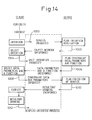
- Fig. 14 is a diagram showing an interactive model
between a client and a server;
- Fig. 15 is an explanatory diagram concerning a role
of an agent-role server;
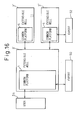
- Fig. 16 is a block diagram showing an interactive
information processing system with an agent capability in
accordance with the second embodiment of the present
invention;
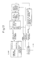
- Fig. 17 is a conceptual diagram showing consistency
of each transaction;
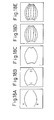
- Figs. 18A to 18E are explanatory diagrams concerning
stages of drawing flow lines;
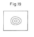
- Fig. 19 is a diagram showing an example of a cell
picture;
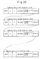
- Fig. 20 is a diagram showing a template for a
segment;
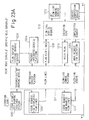
- Fig. 21 is a diagram showing templates for lines
with a modifier "flow" appended;
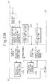
- Fig. 22 is a diagram showing an attribute field in a
template for coping with a modifier "featured";
- Figs. 23A, 23B, 24A and 24B are diagrams showing a
sequence of drawing a textured picture;
- Fig. 25 is a diagram showing a hierarchical
structure of an object network;
- Fig. 26 is a diagram showing an example of a generic
object network; and
- Fig. 27 is an explanatory diagram concerning
parallel possessing.
-
DESCRIPTION OF THE PREFERRED EMBODIMENTS
-
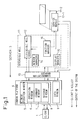
Fig. 1 shows an interactive information processing
system having a field expansion facility in accordance
with the first embodiment of the present invention. The
system comprises an extensible WELL system 11 made by
implementing field expansibility in the aforesaid WELL
system, a common platform 4 to be produced by the
extensible WELL system 11, a communication manager 10
lying between the common platform 4 and extensible WELL
system 11 and serving as one of service managers for the
extensible WELL system, a plurality of service modules
17-1, 17-2, etc., that are packaged in order to execute
unit transactions in reality. When this system is
regarded as a server 3 serving a client, the server 3
interacts with the client through the common platform 4.
-
The common platform 4 includes a network window 5,
an operation window 6, a command window 7, a message
window 8, and a data window 9. The network window 5 is
used by the client (user) 1 for controlling the whole
system. The operation window 6 is used to render an
object network having noun objects as nodes and verb
objects as branches, and allows the client (user) 1 to
select any of the noun and verb objects. The command
window 7 is used to render options and allows the client
to select any of the options. The message window 8 is
used to render messages sent from the system to the
client and allows the client to enter responses if
necessary. The data window 9 is used to render the
results of transactions and allows the client 1 to
designate points, segments, or any other entities.
-
For smoother progress of an interactive process, it
is effective to assign the role to a service process. As
for expression symbols, human beings find images and
graphics more instinctively understandable at sight than
texts. By contrast, machines prefer logic descriptions.
Therefore, the communication manager 10 is included as
one of the plurality of service managers for the
extensible WELL system. The communication manager 10
converts an instruction entered by the client 1 through
the common platform 4 into data recognizable by the
service modules 17-i, and then passes the resultant data
to the service modules 17-i. The communication manager
10 in turn renders as many messages and data provided by
the service modules 17-i as possible in the form of
visible objects in the common platform 4. Thus, flows of
data between the service modules 17-i and common platform
are managed indirectly via the communication manager 10.
Since the communication manager 10 thus manages an
interactive process in a centralized fashion, the
expansibility of the extensible WELL system is
guaranteed.
-
Data conversion between the extensible WELL system
11 independent of any field and the service modules 17-i
dependent on fields is achieved by the communication
manager 10. The presence of the communication manager 10
makes it possible to handle data concerning a variety of
fields. The versatility of the extensible WELL system
itself will not be impaired.
-
The service managers for the extensible WELL system
include not only the service manager 10 but also a window
manager 14, a display manager 15, and a function manager
16. The window manager 14 produces the common platform 4
made up of various windows 5 to 9. The display manager
15 converts data to be rendered in the common platform 10
into a visible object and delivers it to the
communication manager 10. The function manager 16
manages the plurality of service modules 17-1, 17-2,
etc., which are stored as subroutines or functions, in a
centralized fashion. An instruction entered by a client
through the operation window in the common platform 4 is
transferred to the function manager 16 via an extensible
WELL kernel 12. In response to the instruction, the
function manager 16 selects a required service module and
calls the service module.
-
The
extensible WELL kernel 12 is responsible for the
processing below:
- (1) retrieving an associated object network
according to an instruction issued by a client;
- (2) identifying the state of data (identifying a
process and selecting a function to be executed next);
- (3) analyzing an event (identifying an event sent
through each window and calling a procedure that handles
the event and resides in the system); and
- (4) making a request for execution of a function
(appending constraints to a generic function and making a
request for execution of the function).
-
-
The interactive information processing system shown
in Fig. 1 is implemented in a workstation or personal
computer having a multi-window facility.
-
Fig. 2 is an explanatory diagram concerning the
field expansibility of the extensible WELL system. When
the extensible WELL system 11 is provided with, for
example, an "object network A" 19A, it becomes a
processing system dedicated to field A 18A. A definition
of "Window A" is appended to a definition of the object
network A. For execution, "service module A" required
for handling field A is called. Service module A
consists of a plurality of service modules. Likewise,
when the extensible WELL system 11 is provided with
"object network B" 19B, it becomes a processing system
dedicated to "field B" 18B. When the extensible WELL
system 11 is provided with an element/structure network
19C for use in producing and coloring color images, a
color image producing/coloring system 18C' referred to as
a Window-based Elaboration Language for Picture
Processing and Painting (WELL-PPP) indicated with a
dashed line in Fig. 2 is constructed. The object
networks dedicated to specific fields are designed using
a technique described in the U.S. Patent Application
No.08/279,861, and are placed in memory.
-
As described previously, the extensible WELL system
11 has the ability to modify (replace) a graph-structure
object network at the time of execution so that the
object network will has field expansibility. This
ability of the extensible WELL system 11 and the ability
thereof to produce and edit a new object network are, as
shown in Fig. 2, referred to as a "graph-structure
editor."
-
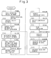
Fig. 3 is a flowchart describing the operations of
the system shown in Fig. 1. Processing steps will be
described below.
-
At step S1, assuming that the system is adapted for
the field of color image producing/coloring 18C, the
extensible WELL kernel 12 calls the object network 19
according to an instruction entered by a client.
-
At step S2, in response to the instruction, the
graph-structure editor stores the object network in a
work space in the WELL kernel 12.
-
At step S3, the WELL kernel 12 activates the window
manager 14 and display manager 15 shown in Fig. 1, and
receives responses from the managers. With arbitration
by the communication manager 10, the object network is
rendered in the operation window 6.
-
At step S4, a client views the object network
through the operation window 6, and designates the whole
or part of the object network so as to express his/her
intention.
-
At step S5, the kernel 12 recognizes the situation
via the communication manager 10, calls a template
associated with the object, and displays it at a location
to be processed.
-
At step S6, the service module prepares a space for
the template.
-
At step S7, the common platform extracts constraint
data from the template if any, and renders the constraint
data in the message window 8.
-
At step S8, the client selects desired constraint
data from the rendered constraint data.
-
At step S9, the kernel 12 recognizes the situation
via the communication manager 10 and plans execution.
-
At step S10, the service module executes desired
processing (for example, drawing or coloring).
-
At step S11, the resultant drawing is displayed in
the data window 9.
-
At step S12, the client evaluates the resultant
drawing and enters a subsequent instruction.
-
Assuming that the object network 19C designed for
color image coloring is selected as an object network,
the actions of the interactive information processing
system in accordance with the present invention will be
described in detail.
-
An element network that is an object network is
composed of a frame section for rendering the appearance
of an individual object and producing the outline
defining an area and a color section for assigning
attribute values according to lines and an area defined
with the lines.
-
Fig. 4 shows an example of the element network. A
frame section 20 in the left-hand part of Fig. 4 is
comparable to the above frame section, while a color
section 21 in the right-hand part thereof is comparable
to the above color section.
-
The frame section 20 produces entities including
points and segments. The color section 21 specifies
attributes of luminance and chromaticity. Points and
segments are represented by noun objects, while drawing
and identifying are represented by verb objects. The
noun objects represent entities as described below.
-
None: represents an unprocessed state.
-
Point: represents a point essential to an outline
and is referred to as a principal point.
-
Point Sequence: represents an order in which the
principal points are linked.
-
Line: represents a state in which line segments are
linked to complete one line.
-
Region Segment: represents a region defined with one
horizontal scanning line in an image.
-
Region: represents region segments vertically linked
along an image.
-
Colored to: represents items describing luminance
and chromaticity. Identify for use in linking the frame
section with the color section is defined as follows:
- Identify: represents specifying of an object to be
processed.
-
-
Using the network shown in Fig. 4, a client can
achieve drawing. Drawing modes are described in the U.S.
Patent Application No.08/279,861 (entitled "Language
Processing System Based on an Object Network").
-
Fig. 5 shows a mode of color image
producing/coloring in a system having a common platform.
In Fig. 5, reference numerals 1, 3, and 4 denote the same
components as those in Fig. 1.
-
Through a window appearing in the common platform 4,
the client 1 visually understands that an element network
has been implemented. The client 1 then selects the
intention of drawing (or a class). In this example,
Colored Point is selected in order to provide a point
with luminance and chromaticity. In response to the
client's request for coloring a point, the server
prepares a template for use in storing information and
asks the client to which point color information should
be allocated. The template will be described later.
When the client 1 specifies a point using Identify, the
server 3 identifies the point by referencing an index in
the associated template and asks the client 1 for
luminance and chromaticity data concerning the point.
When receiving the data as a response from the client 1,
the server 3 inputs the data into the template and
displays a resultant color image in a window. With the
display, the client 1 discerns the resultant image,
evaluates it, and then proceeds to selection of a
subsequent intention. Thus, the client 1 recognizes
his/her own intention returned by the server 3 as a
visible object. Points or lines drawn as mentioned above
are managed in the form of noun objects. Processing
performed on the individual noun objects are given in the
form of verb objects.
-
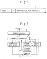
The communication manager 10 manages correlations
between data so as to maintain the expansibility of the
extensible WELL system. The data is therefore managed in
a centralized fashion using templates. Attributes can be
set freely in the templates.
-
Fig. 6 shows an example of a format of a template.
A template 22 is composed of an index field containing an
index assigned to each object associated with the
template, a coordinate field containing coordinates of
the object, and an attribute field containing attributes
of the object. Note that a combination of data having a
data structure of the above template and representing the
correlation between a visible object appearing in a
common platform and data handled within a server may also
be referred to as a template. Templates are managed on
the basis of indices by the service modules 17-i. What a
client enters through the data window 9 is coordinates
indicated in the data window 9. The service modules 17-i
cannot retrieve an index of a template using coordinates.
The communication manager 10 therefore converts
coordinates into an index and delivers the index to the
service modules 17-i.
-
Fig. 7 shows a role of the communication manager 10.
In Fig. 7, reference numerals denote the same components
as those in Fig. 1. As shown in Fig. 7, when a client's
intention is to be input to the system via the common
platform 4, it is first fed to the communication manager
10 without fail and then transferred to the kernel 12,
managers 14 and 16, and then service modules 17-i. The
communication manager 10 is therefore a sole manager
directly connected to the common platform 4 and manages
interactive processes in a centralized fashion.
-
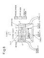
Fig. 8 shows the actions of the communication
manager 10. In Fig. 8, reference numerals 6, 8, 9, 10,
12, 14, 15, and 17 denote the same components as those in
Fig. 1.
-
A point (x,y) designated by a client is transferred
to the communication manager 10 through the data window
9. A message is transferred through the message window
8. An operation is transferred through the operation
window 5. The information is transferred among the
managers 14 and 15, kernel 12, and service modules 17 via
the communication manager 10.
-
The template shown in Fig. 6 is used for point or
line data, or graphic or image data. This means that the
point or line data and graphic or image data is handled
in the common platform. The data is represented in the
form of noun objects serving as nodes in an object
network. When a client wants to render or reference
data, he/she uses a mouse or the like to point to a
reference of data appearing in the common platform 4 and
references or designates a noun object in the object
network. This kind of reference designation ability is
intended mainly to enable a client to designate data
serving as an objective of a verb object. For rendering
an entity, an actual point, line, graphic, or image is
displayed as an resultant drawing provided by the server
in the common platform 4. For storing and processing
data, the server processes data stored in line with a
specific data structure (for example, an indexed list
structure or a raster structure).
-
Referring to Fig. 9, the effects of the
communication manager 10 and a template will be described
using an example.
-
Reference numeral 9, 10, 12, 14, 15, and 17-i denote
the same components as those in Fig. 1. Reference
numeral 23 denotes a work buffer installed in the kernel
12. 23' denotes an example of the contents of the buffer
23. 19C denotes an object network.
-
Assuming that color image producing/coloring is in
progress, the object network 19C dedicated to the color
image producing/coloring supplies templates associated
with points and lines as data to a service module 17-i
concerned. Copies of the templates are written in the
buffer 23 (which may reside in the communication manager
10) in the kernel 12 by the service module 17-1 in such a
format as the contents 23' of the buffer shown in Fig. 9.
The contents of the buffer 23 include, for example, (i) a
point specified with an index 1 and characterized by
coordinates (50, 40), and uncertain (expressed with ?)
chromaticity and luminance (attributes), (ii) a point
specified with an index 2 and characterized by
coordinates (80, 250) and uncertain chromaticity and
luminance, and (iii) a point specified with an index 3
and characterized by coordinates (270, 400) and uncertain
chromaticity and luminance.
-
In this state, when the client 1 designates
coordinates (80, 250) through the data window 4 so as to
specify one point, the communication manager 10 detects
the client's entry. The window manager 14 detects the
coordinates and posts them to the communication manager
10. The communication manager 10 retrieves an index
associated with the coordinates (80, 250) of the
specified point. In other words, the communication
manager 10 references the buffer 23 to find that a
template containing the coordinates (80, 250) has the
index 2. The communication manager 10 then proceeds to a
subsequent transaction.
-
Coordinates transferred are collated with templates
from which coordinates of principal points defined using
the frame section are copied to a work space. When
identical or similar coordinates are retrieved, an index
associated with the coordinates is specified. The
communication manager 10 sends the index to the service
module 17-i concerned and thus passes control thereto.
The service module 17-i updates values in the template
specified with the index. For example, coordinate values
are modified or a luminance value is described as an
attribute. The updated template is converted into a
visible object by the display manager 15 and rendered in
the data window 9. In this case, the defined point is
highlighted so that it will be easily discernible by a
client. The extensible WELL system exchanges information
with the service modules 17-i that manage data on the
basis of indices. This system configuration realizes a
highly expansible system independent of a specific field,
and provides an environment in which irrespectively of a
field, a client can respond to intentions of a server
while viewing visible objects produced by the display
manager 15.
-
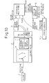
Fig. 10 is an explanatory diagram concerning
information exchange. Reference numerals 1, 4, 7, 9, 10,
12, 14, 16, and 17 denote the same components as those in
Fig. 1.
-
When transferring information to or from a server, a
client uses windows without any exception. The system
must therefore stay in a wait state so as to pass control
through windows. When driven with a client's intention,
the system is said to be event-driven. When waiting for
data to be entered through a window so as to pass
control, the system is said to be data-driven. For
example, when Colored Point is selected, the system is
"event-driven." However, unless luminance or chromaticity
data is given, any function cannot be executed, the
system enters a wait state. In this state, the system is
said to be "data-driven."
-
In Fig. 10, when the client 1 designates a point of
certain coordinates and thus places the system into the
event-driven state, as described in conjunction with Fig.
9, the window manager 14 informed of the fact by the
communication manager 10 reports the coordinates (for
example, (80, 250)). The associated index 2 is then
checked, and a template specified with the index is
posted to the service module 17-i concerned.
-
When the client 1 wants to color the point, the
kernel 12 analyzes the state of noun object Colored Point
shown in Fig. 4. After completing the analysis, the
kernel 12 issues a function execution request to the
function manager 16. In response to the request, the
function manager 16 specifies a function according to
provided constraints. The service module 17-i concerned
determines if the function is executable. If data is
insufficient to execute the function, required work is
performed via the kernel 12. For example, when the
service module attempts to input luminance or
chromaticity information to the template representing the
point specified by the client, if the luminance or
chromaticity information is uncertain, the function
cannot be executed. The system then becomes data-driven.
The command window 7 needed for data input is opened, and
luminance samples or color samples are displayed in the
command window 7. The system thus waits for client's
entry.
-
The service module 17-i concerned opens a required
window (for example, the command window 7 in Fig. 10) and
waits for a user's response. The command window 7 may
become unnecessary after the response is received. Some
service modules require numerous windows. The number of
windows to be opened must be minimized. The window
manager 14 is therefore provided with a table listing
states of windows. Based on the contents of the table,
unnecessary windows are deleted automatically.
-
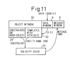
Fig. 11 is an explanatory diagram concerning the
actions of a check module. Reference numeral 8 denotes a
message window. 9 denotes a data window. 22 denotes a
template. 24 denotes a check module. 25 denotes
constraints. 26 denotes an object network.
-
A client may want to check the validity of data
he/she has produced through a data window in the course
of work on an object network. An item the client wants
to check is regarded as one constraint. The constraints
25 are appended to each of noun objects in the object
network 26. The server achieves checking by comparing
the contents of a template with the constraints. What
counts here is how a server identifies a template to be
processed. The extensible WELL system utilizes the
capability of a communication manager for the
identification. The communication manager 10 manages the
consistency in data between a client and a server on the
basis of the data contained in a template residing in an
object network. Based on coordinates (X, Y) of a point a
client specified by clicking a mouse, as described with
reference to Fig. 9, information specifying an object to
be processed is retrieved from the template 22 and
transferred to the check module 24 (that is a service
module for collating the contents of a template with
constraints). Based on the information, the check module
determines whether the constraints are satisfied. The
result of the determination is posted to the client
through the message window. The checking performed by
the check module 24 is utilized to check if a status
shift from Point to Colored Point is achieved correctly.
Another constraining jobs can, similarly to another
service modules, be implemented by preparing responsible
managers.
-
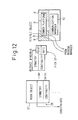
Fig. 12 shows a mode of rendering constraints.
Reference numerals 6, 8, 9, and 10 denote the same
components as those in Fig. 1. Reference numeral 25
denotes constraints shown in Fig. 11. 27 denotes a noun
object.
-
It may become necessary to inform a client of
constraints appended to a line (segment) drawn during
graphic drawing. The actions of managers in this state
will be described in conjunction with Fig. 12.
-
The line (segment) itself represents the state of
data and is therefore regarded as one noun object 27.
The constraints 25 are appended to the noun object 27.
The constraints 25 that can be imposed on a line
(segment) may be continuity and symmetry (indicating
whether a segment is symmetric with respect to an axis or
a point).
-
The constraints 25 appended to the noun object 27
are rendered in the message window 8 via the
communication manager 10 and thus reported to a client.
In Fig. 12, "Symmetry-Point, Axis" shown as the contents
of the message window 8 is an indication asking which be
realized; point symmetry or axial symmetry. A client
picks up either "Point" or "Axis" of the "Symmetry-Point,
Axis" so as to post his/her intention to the server.
-
In response to an activation request entered by a
client through the message window 8, the check module 24
shown in Fig. 11 is activated by the function manager 16
(Fig. 1). The check module 24 uses the message window 8
to issue an identification request to the client. The
client selects a visible object through the data window
by clicking the mouse, thus transferring data concerning
the object to the communication manager 10. The data is
converted into an index of an item associated with the
object as shown in Fig. 9 by the communication manager
10, and then sent to the check module 24. Using the
index, the check module 24 retrieves attributes from a
template specified with the index and checks it. The
result of the checking is posted to the client through
the message window.
-
Fig. 13 is an explanatory diagram concerning
identification. Reference numerals 6, 8, 9, 10, 14, and
17-i denote the same components as those in Fig. 1.
-
As described above, when the check module 24 issues
an identification request to a client, the client
designates, for example, a segment as shown in Fig. 13
through the data window 9. Responsively, the window
manager 14 operates to post relevant data to the
communication manager 10. The communication manager 10
becomes aware of an associated index and transfers the
index to the check module 24. The check module 24 then,
as shown in Fig. 11, checks the data specified with the
index. The result of the checking is rendered in the
message window 8.
-
Next, an interactive information system having an
agent capability in accordance with the second embodiment
of the present invention will be described.
-
For solving certain problems and obtaining results
of processing, a service system is used to realize an
intention induced by curiosity. Thinking of an
interactive model between a client and server shown in
Fig. 14, it may be worth while defining an organization
of intentions in the form of a graph-structure object
network. The contents of the object network are
expressed as an interactive sequence in which services
are executed sequentially or in parallel to realize
individual intentions. In the left-hand of Fig. 14, work
performed by a client is indicated with rectangles. In
the right-hand thereof, jobs performed by a server are
indicated with rectangles. In the center of Fig. 14, a
rectangle drawn with a dashed line means that a
display-oriented process including a display facility
such as a display unit is interposed between the client's
work and server's jobs.
-
A client enters the name of a service interesting
him/her so as to express his/her intention, and thus
requests a display-oriented process to execute the
service (step 1000). In response to the request, a
server plans intention realization and provides an object
network used for transactions (step 1002).
-
While viewing the provided object network in a
screen, the client selects an intention (step 1004). The
selected unit intention is fed to the server. The server
in turn plans constraint data, parameters, and a
function, and then presents the resultant plan in a
screen (step 1006).
-
The client selects the presented data, parameters,
and function (step 1008). The server plans service
execution on the basis of the selected data, parameters,
and function, and presents a resultant plan in a screen
(step 1010). The client evaluates the resultant plan and
then selects a subsequent intention (step 1012).
-
As mentioned above, the client and server cooperate
with each other so as to realize intentions. In other
words, the client requests the server to provide unit
intentions while selecting intentions. Responsively, the
server plans constraints required for service execution
and informs the client of the necessities of the
constraint plans. This kind of interactions are
characteristic of an interactive system.
-
For more effectively realizing the interactions
between a client and a server such as the ones shown in
Fig. 14, it may worth while interposing an agent-role
server 3' playing the role of an agent between a client 1
and specific role servers 3".
-
The agent-role server 3' plans a service according
to an intention of the client 1 (step 1100), retrieves a
specific role server for executing the service plan (step
1101), plans service assignment, and makes a request for
executing the service plan by means of a subordinate
display-oriented process 2-2 (step 1102). The specific
role server 3" plans execution of the assigned service
and supplies the results of execution to the subordinate
display-oriented process 202 (step 1104). The agent-role
server 3' checks the results of execution and presents
the results of execution to the client 1 by means of a
display-oriented process 201 (step 1106). The
subordinate display-oriented process 202 is designed to
be "display-oriented" in an effort to facilitate system
development of the specific role server 3" alone.
Similarly, the display-oriented process 201 is usable for
development of the agent-role server 3'.
-
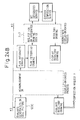
Fig. 16 shows the outline configuration of an
interactive information processing system having an agent
capability in accordance with the second embodiment of
the present invention. The interactive information
processing system is adapted for the above
display-oriented and subordinate display-oriented
processes. Each of the agent-role server 3' and two
specific-role servers 3" is realized with the extensible
WELL system 11, which is described with reference to Fig.
1, having the common platform 4. In system development,
a client of the agent-role server 3' is an expert 50
well-familiarized with the jobs of an agent. Clients of
the specific-role servers 3" are experts 52
well-familiarized with specific jobs. Each of the
experts 50 and 52 designs object networks, templates,
constraints, and required service modules through the
common platform 4. When a system has been developed and
becomes usable, the client of the agent-role server 3' is
taken over by a user 54 of the system. The clients of
the specific role servers 3" are taken over by the
agent-role server 3'.
-
As described previously, data conversion is
performed using a template between the
servers 3 and 3"
and their clients. Table 1 lists examples of templates.
| | Client | Server |
| Template containing point or line data. | Points or lines are displayed as entities. (entity designation) | An index is used to specify the template. |
| A template is designated while reference to an entity. (reference designation) | Data is transferred all together to the common platform and processed in combination. |
| Template containing graphic or image data | Graphics or images are displayed as entities. | Data is specified using a list structure or raster structure. |
| Reference designation |
| Template containing a data element | A name is designated. | A name header is used to specify the template. |
| Template containing a service (Agent service) | A service structure is first designated in the form of a generic object network. | A service coordination table is supplied. |
| | | A server for executing a service or a server responsible for a service is selected. |
| | During service, a service item or a service name is designated. |
-
Specifically, as far as a template containing point
or line data is concerned, a point or line is displayed
as an entity so that a client can designate any point or
line while referencing the entities. For a server, an
index is used to specify a template. Data contained in
the template specified is transferred all together or
processed in combination. As far as a template
containing graphic or image data is concerned, images or
graphics are displayed as entities so that a client can
designate any image or graphic with reference to the
entities. For a server, a list structure or raster
structure is used to specify data. As far as a template
containing a data element is concerned, a name is used so
that a client can designate any template. For a server,
a name header is used to specify a template. As far as a
template containing a service (abstracted service of an
agent) is concerned, a service coordination clarifying
programs responsible for specific services is presented
in the form of a generic object network so that a client
can select a desired service. In the course of execution
of a service, a client can enter (i) a service item
having service constraints as parameters and (ii) a
service name. For a server, (i) a service coordination
table is produced, and (ii) a server for executing a
service according to a service item designated by a
client or a server responsible for a service is selected.
-
In the configuration shown in Fig. 16, the number of
specific role servers 3" is not necessarily two but may
be one or more than two. The agent-role server 3' and
specific role servers 3" may be implemented in individual
workstations or personal computers or in a single
workstation or personal computer.
-
In the system shown in Fig. 16, a plurality of
services are executed in parallel within the same
specific role server or different specific role servers.
At this state, constraining relationships among services
must be clarified and reflected on transactions, so that
transactions processed by a plurality of service modules
will be mutually consistent.
-
Fig. 17 conceptually shows a situation in which
consistency is attained among transactions. When an
attempt is made to execute in parallel services A to N
derived from intentions A to N of a client shown in the
left-hand part of Fig. 17, constraints are usually
imposed on execution of the services. The constraints
are classified into temporal constraints and modal
constraints. The former is comparable to execution-time
restraints or inter-service temporal control, while the
latter is comparable to inter-service modal control. The
contents of a combined service executed with the
restraints imposed or control applied are checked, and
the result of checking is presented to a client through a
window. The client evaluates the result of checking.
-
The aforesaid configuration and actions will be
described on a supplemental basis using examples.
-
In Fig. 15, the agent-role server 3' plans a service
according to an intention of the client 1 (step 1100).
For example, when a client has the intention of drawing
such a textured picture as a fish having numerous scales,
the intention of drawing a textured picture is sent as a
service request to the agent-role server 3'. The
agent-role server 3' plans a service in which flow lines
and cell pictures are drawn and combined to form a
textured picture. For drawing flow lines, the element
network shown in Fig. 4 can be employed because it is
designed to draw element pictures. Specifically, a
partial network including noun objects from Point to Line
in Fig. 4 is rendered as an object network. For
achieving this rendering, the agent-role server 3'
retrieves noun object Line to find that a word "flow"
resides in the element network. The agent-role server 3'
then renders the partial object network together with the
display of flow lines in the common platform 2.
-
Using the partial object network, the client 1 draws
curves A and B to outline a fish body as shown in Fig.
18A. Next, as shown in Fig. 18B, the client 1 draws
lines C and D. At this time, the agent-role server makes
an inquiry "How may lines do you want to draw between
lines A and B?" through the message window 8. When the
client 1 types 5 in response to the inquiry, as shown in
Fig. 18C, ten points are determined. Consequently, five
interpolative curves are drawn. In response to an
inquire "At how many points do you want to dot the
interpolative curves?," when 7 is typed, each of the
interpolative curves is, as shown in Fig. 18E, dotted at
seven points so that scales can be drawn on the points.
-
At the same time, an object network serving as an
element network is rendered together with a cell picture
so that a scale image can be drawn. The client draws a
color scale image as shown in Fig. 19 using the object
network.
-
Assignment of a service to a certain specific-role
server 3" is performed at step 1102 in Fig. 15 at which
service assignment is planned (service specification).
At this step, the subordinate display-oriented process
202 whose client is the agent-role server 3' provides
predetermined display. Consequently, the agent-role
server 3' communicates with the specific role servers 3".
When the agent-role server 3' communicates with the
plurality of specific role servers 3", in this example,
when flow lines and a cell picture are processed,
constraints must be stipulated in advance between the
specific role servers 3" and observed for execution of a
service.
-
It is therefore required to define templates in
advance. A point template is defined as shown in Fig. 6.
A field of "attributes for point (x,y)" in Fig. 6
contains attributes of luminance and chromaticity of the
point concerned. A line template is, as shown in Fig.
20, composed of templates associated with principal
points 1, 2, etc., and n among points at which the line
intersects scanning lines (See Fig. 10) and pointed to by
pointers.
-
In Fig. 20, each point template specifies a
luminance and a chromaticity vector as attributes. This
is because when an element network that is an object
network having noun objects Point and Colored Point
defined is employed, it is preferable to set a luminance
or chromaticity vector as attributes in a point template
so that the meaning of a modifier "colored" can be
expressed.
-
With the addition of an adjective "flow" to a noun
"line," an area for accommodating an additional attribute
must be defined in a template. The area may be defined
in advance. Alternatively, when needed, the area may be
defined using a graph-structure editor, which is an
extension feature for expanding the capability of the
extensible WELL system.
-
An example of a data structure for data with an
adjective such as a flow line is shown in Fig. 21. In
Fig. 21, reference numeral 30 denotes an index associated
with an "adjective distinguishing a line" such as "flow."
31 denotes an index associated with a "line" specified
with "flow." 32 denotes data (such as the one shown in
Fig. 20) concerning the "line."
-
When an adjective "featured" is appended to "colored
point" to form "featured colored point," a "Feature name"
area as shown in Fig. 22 is defined in an attribute field
of a colored point template. "Edge," "highlight," or
"none" is described in the "Feature name" area. When
"edge" is described, the point is recognized to belong to
an edge in terms of the luminance and chromaticity
vector. When "highlight" is described, the point is
highlighted. When "none" is described, the point has no
feature.
-
For four lines A, B, C and D shown in Figs. 18A and
18B, four line templates are prepared. Through the
message window 8 in the common platform 4, the client 1
makes a request for producing line templates associated
with five flow lines. In the course of drawing a cell
picture, a template is produced in association with a
noun object selected in an object network (such as the
one shown in Fig. 4). When noun object Colored Region is
selected, a raster-structure template having luminance
and chromaticity data is produced.
-
The center of each scale image drawn as mentioned
above is aligned with each of dots on flow lines. The
size of each scale image is then determined, and then the
scale images are mapped. In this case, constraints are
required.
-
By this time, a distance between adjoining dots on
the flow lines is determined for the dots. "Distance" is
defined as an attribute of a flow line. A value of a
distance is calculated after drawing is completed. The
distance value is stored in a point template for each
dot. Similarly, "scale" is defined as an attribute of a
cell picture. A constraining relationship between the
scale value and distance value is determined as "a
diameter of a scale in a cell picture = a distance
between adjoining dots on a flow line." The specific
role server 3 is asked to achieve mapping while keeping
the relationship.
-
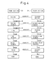
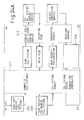
Figs. 23A, 23B, 24A and 24B are flowcharts
describing textured picture drawing.
-
The work of the client 1 is described sequentially
from above in the left-hand parts of Figs. 23A, 23B, 24A
and 24B. The jobs of the agent-role server 3' are
described sequentially in the center parts of Figs. 23A,
23B, 24A and 24B. The jobs of the specific-role server
3" are described sequentially from above in the
right-hand parts of Figs. 23A, 23B, 24A and 24B. In
Figs. 23A, 23B, 24A and 24B, reference numerals 1, 2-1,
2-2, 3' and 3" denote the same components as those in
Fig. 15. An arrow A in the bottom of Fig. 23B points to
an arrow A in Fig. 24A.
-
In Figs. 23A and 23B, the client 1 having the
intention of drawing a textured picture makes a request
for a textured picture drawing service (step 1200). The
agent-role server 3' plans a textured picture drawing
service (step 1202), and sets an integrated service
platform (step 1204). The client 1 who wants to display
flow lines such as those shown in Fig. 18D makes a
request for displaying flow lines (step 1206).
-
The agent-role server 3' retrieves a flow-line
drawing plan (step 1208) and requests the specific role
server 3" to set a flow-line drawing service (step 1210).
The flow-line drawing service set by the specific role
server 3" is presented to the client 1 via the agent-role
server 3' (step 1210). The client 1 having the intention
of drawing flow lines makes a request for displaying a
flow-line screen (step 1212). The agent-role server 3'
requests the specific-role server 3" to display the
flow-line screen (step 1214). The flow-line screen is
then displayed for the client 1 and constraints are
presented at the same time (step 1216). When the
constraints are acknowledged (step 1218), the agent-role
server 3' performs computation so as to display flow
lines and dots (step 1220), and then displays them for
the client 1. The client 1 makes a correction request if
necessary (step 1222).
-
The client 1 then expresses the intention of drawing
a cell picture (step 1224). As shown in Figs. 24A and
24B, the agent-role server 3' and specific role server 3"
work together to set a common platform for a cell
picture. When the client 1 expresses the intention of
drawing a cell picture (step 1226), a cell-picture screen
is displayed and constraints are presented (step 1228).
When the client acknowledges the constraints (step 1230),
the results of processing the cell picture are integrated
into the integrated service platform. Thus, the system
waits for the client 1 to evaluate the results of
processing.
-
As mentioned above, two jobs of flow-line drawing
and cell-picture drawing can be executed in parallel.
When the drawing is completed, an integrated drawing
process is started. The specific role servers 3" that
are three servers for flow-line drawing, cell-picture
drawing and integrated drawing is subordinated to the
agent-role server 3'. The element network shown in Fig.
4 is used as an object network for controlling the
servers. For flow-line drawing, noun objects from Noun
to Line shown in the left-hand part of Fig. 4 are
employed. These noun objects alone are rendered in the
common platform for the sole purpose of line drawing and
used by the client 1 within the display-oriented process
201. For cell-picture drawing and integrated drawing,
the whole of the element network shown in Fig. 4 is used
as an object network by the client.
-
The results of processing performed by the
specific-role servers 3" are displayed in the common
platform interposed between the client 1 and agent-role
server 3' via the agent-role server 3'.
-
Notes on interactions are as follows:
- (1) An abstracting service provided by the
agent-role server 3' is defined in the form of a generic
object network. The generic object network is specified
as a specific object network by appending parameters or
constraints.
- (2) Using attributes of individual objects received
from a parent server (for example, agent-role server 3'),
the specific role server 3" executes a job. As a result,
the attributes are delivered as synthesized attributes to
the parent server. The agent-role server 3' uses the
attributes to impose constraints, obtain new data, or
activate a checking facility.
- (3) Constraints fall into, as shown in Fig. 17,
modal constraints and temporal constraints.
-
-
The generic object network resembles the element
network shown in Fig. 4. For drawing a textured picture,
a client issues a request for drawing a textured picture
to the agent-role server 3'. A generic object network
provided by the agent-role server 3' is set as an
integrated service platform in order to facilitate
communication between the client 1 and the agent-role
server 3'. The aforesaid pictures are displayed in the
integrated service platform. This kind of network is
produced by the graph-structure editor serving as a
facility of the extensible WELL kernel.
-
Fig. 25 shows a hierarchical structure consisting of
object networks. As variables are generalized to create
a formula in the field of mathematics, so parameters and
constraints are generalized (abstracted) to form a
generic object network 33. Specific parameters and
constraints 34 for use in running a specific job are
installed in the generic object network 33, whereby a
specific object network 35 for running the specific job
is produced.
-
Fig. 26 shows a generic object network for use in
performing textured picture drawing through interactions
between the agent-role server 3' and the specific role
server 3". In Fig. 26, templates representing noun
objects encircled with squares are produced by an expert
that is a designer of the textured picture drawing
system.
-
When a client selects noun object Flow Line, part of
the graph structure of the element network shown in Fig.
4 including noun objects from Line to None is presented
as an aid for a partial drawing process for drawing flow
lines to the client 1 by the specific role server 3" via
the agent-role server 3'. Using part of the graph
structure, the partial drawing process proceeds as shown
in Figs. 18 to 18E.
-
The templates set in the element network are used as
they are. When a modifier "flow" is appended to "line,"
- (i) another attribute area must be defined in the
attribute field in the line template and a constraint
field must be defined in the line template, and (ii) for
textured-picture drawing, positions of dots shown in Fig.
18E must be determined to map a cell picture but lines
need not be specified.
-
-
For drawing flow lines, flow lines are drawn as
shown in Fig. 18D on the drawing of Fig. 18B.
Constraints or a sub-network must be designated for
drawing dots shown in Fig. 18E.
-
When a modifier "flow" is appended, as described
previously, the agent-role server 3' asks the client to
define a distance between adjoining dots on flow lines
and a distance between adjoining flow lines under the
designated constraints. An inquiry and a response are
made through the message window 8 in order to determine
the number of dots. The resultant value is set in the
field for "constraints on noun objects 25" shown in Fig.
11. The positions of the dots are then determined. The
dots in Fig. 18E are used to specify positions to each of
which a cell picture is mapped. The dots are not
displayed in an actual textured picture drawing screen
and deleted at the time of displaying a textured picture.
-
The same applies to a cell picture. When noun
object Picture is selected, a color picture is drawn
using the element network. Thereafter, the color picture
is mapped to each of the dots shown in Fig. 18E. At this
time, since Picture is modified with "cell," the size of
each picture is determined with a distance between
adjoining dots on flow lines. It is possible to
determine a ratio of the size of a cell picture to the
distance between adjoining dots on flow lines. This is
considered as materialization of an intention of imposing
a constraint shown in Fig. 17.
-
A role played by a specific role server is thought
to execute services for materializing basic noun objects
and defined using a specific object network. By
contrast, an agent-role server is responsible for
imposing constraints on noun objects and attaining
consistency among services.
-
Described above will be discussed in terms of
inheritance data and synthetic data that are
object-oriented attributes mentioned previously.
-
Inheritance data Based on inheritance data, a
template is received from an agent-role server for making
a request for a certain job. In other words, a template
in which data is stored in line with a data structure
determined as a template format according to the
inheritance data is received. A specific role server
responsible for the job resides in an extensible WELL
system and executes the job. Execution may be achieved
by the specific role server itself or by any other
service module.
-
Synthetic data A specific role server requested to
execute a job on the basis of the inheritance data
executes the job. A template format that is a data
structure in which the results of executing the job are
stored has already been supplied together with the
request. The results are then stored in the data
structure, and returned as a response to the agent-role
server. The sequence is carried out through a common
platform (installed in the specific role server)
interposed between the agent-role server and specific
role server by a communication manager supporting the
common platform.
-
The relationship between the agent-role server 3'
and specific role server 3" is identical to that between
a client and a server under the control of an extensible
WELL system. However, when the agent-role server uses a
plurality of data as inheritance data to request a
plurality of specific role servers to run a job, the
agent-role server must perform constraining. For drawing
a textured picture, discrete specific role servers are
requested to draw flow lines and a cell picture
respectively. With the resultant drawings returned,
constraints between the flow lines and cell picture must
be satisfied.
-
Constraining is assigned to a communication manager.
The communication manager performs:
- (1) conversion dependent on a template format (See
Table 1), and
- (2) communication control for attaining consistency
among the contents of a template or templates in the
course of constraining.
-
-
Image processing and picture drawing can be achieved
in a correlative fashion by performing interactive
information processing based on a common platform. For
example, image processing is performed to extract
features; that is, to enhance an edge or highlight a
line. The highlighted line then is moved. When a
left-hand image viewed by the left eye is produced, the
view point is moved to the right eye in order to produce
a right-hand image. Thus, a three-dimensional image is
produced. Moreover, when the corners of eyes move up and
down so that expressions are changed, image processing is
performed to detect the positions of the eye corners in
order to enhance the features of the expressions.
-
Feature detection may not always be executed fully
by a server. A client selects some points at which
distinct features are supposed to be detected, and
designates feature names as constraints. Thus, candidate
points whose features are to be rendered are determined.
Feature points are then selected from among the candidate
points. This procedure is performed using, for example,
the element network in Fig. 4. Assuming that the
client's operations are numbered C1, C2, etc.
time-sequentially and the system's actions are numbers
S1, S2, etc. time-sequentially, the procedure proceeds as
follows:
- Colored Region Segment is designated (C1-1), and
Region Segment having data of a distinct feature is
identified in the data window (C1-2).
- "Featured" is typed and Colored Point is designated,
whereby a request for seeking Featured Colored Point is
sent as a client's intention to the system (C1-3).
-
-
The system confirms the client's intention through
the message window, displays "Seek featured colored
point," and then renders identified Colored Region
Segment (S1).
-
"Highlight" is typed as a constraint for featuring.
The nature of highlight has already been set in the
system.
-
Featured (Highlight) Colored Point is extracted
(S2).
-
A word "Featured (Highlight)" is copied, and a
colored line segment is identified (C3 to S3).
-
Thus, a highlighted line is determined. After
confirming the highlighted line, the client moves it.
The client then moves a new highlighted line and an edge
according to the right and left lines of sight. At this
time, the system executes a picture drawing service so
that an attribute set in Colored can be inherited and
that the feature of the highlighted line can be
maintained. A movement of the highlighted line is
specified by appending a modifier "moved." A moving
vector diagram is used to achieve temporal movements.
-
When a modifier "colored" is appended, areas for
attributes of luminance and chromaticity are defined in a
template concerned. Likewise, when the foregoing
modifiers "highlighted" and "moved" is appended, areas
are defined in a template concerned. These modifiers are
appended to noun objects. As for verb objects, Draw
associated with each of noun objects from Point to Line
Segment is inherited. Constraints such as "at the start
of execution," "during execution," and " at the end of
execution" may be appended to a verb object.
-
The relationships between an execution request and
constraints should be determined so that an execution
request can be made for executing a service. That it to
say:
- (1) only the inheritance attributes provided by the
agent-role server 3' are handled in response to a
request, and the results are returned as synthesized
attributes to the upper-level agent-role server 3.
- (2) An execution request is issued when a client
designates a verb object in an object network. An
execution sequence may be determined using aforesaid
execution units (for example, Draw associated with each
of noun objects from Point to Line).
- (3) As for generic verb objects in a generic object
network, an execution sequence is determined as mentioned
in item (2).
-
-
Constraining is performed to check if temporal
constraints described in conjunction with Fig. 17 are
satisfied.
-
When receiving the results of executing a job, the
agent-role server 3' enters a constraining process. If
any constraint is unsatisfied, the agent-role server 3'
instructs a specific role server, which has returned
synthetic data to the agent-role server 3', to modify an
inheritance attribute and re-execute the job. If the
constraint is still unsatisfied, a route of synthesis is
followed and a pass for asking a client to make a
decision is established.
-
Description has proceeded on the assumption that
only one client is involved. A plurality of clients may
work in cooperation. That is to say, a cooperation agent
for enabling cooperation is installed as an upper
hierarchical level of clients. Thus, a common platform
can be shared by the clients in cooperation.
-
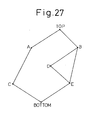
For parallel processing, a structure of an object
network may be expressed as shown in Fig. 28 using noun
object Top as a destination and Bottom as a departure
point. Bottom is comparable to None in Fig. 14.
-
In Fig. 27, assuming that jobs in progress are C and
D, subsequently executable jobs are A and D. When
parallel execution of A and D is completed, jobs A and B
may be handled next. Thus, a structure of an object
network is analyzed so that actions of a plurality of
servers can be controlled dynamically along with the
progress of parallel processing.