EP1718809B1 - Dent pour godet de pelle mecanique. - Google Patents
Dent pour godet de pelle mecanique. Download PDFInfo
- Publication number
- EP1718809B1 EP1718809B1 EP05702423A EP05702423A EP1718809B1 EP 1718809 B1 EP1718809 B1 EP 1718809B1 EP 05702423 A EP05702423 A EP 05702423A EP 05702423 A EP05702423 A EP 05702423A EP 1718809 B1 EP1718809 B1 EP 1718809B1
- Authority
- EP
- European Patent Office
- Prior art keywords
- tooth
- main body
- pin means
- hereinbefore
- work element
- Prior art date
- Legal status (The legal status is an assumption and is not a legal conclusion. Google has not performed a legal analysis and makes no representation as to the accuracy of the status listed.)
- Not-in-force
Links
Images


Classifications
-
- E—FIXED CONSTRUCTIONS
- E02—HYDRAULIC ENGINEERING; FOUNDATIONS; SOIL SHIFTING
- E02F—DREDGING; SOIL-SHIFTING
- E02F9/00—Component parts of dredgers or soil-shifting machines, not restricted to one of the kinds covered by groups E02F3/00 - E02F7/00
- E02F9/28—Small metalwork for digging elements, e.g. teeth scraper bits
- E02F9/2808—Teeth
- E02F9/2816—Mountings therefor
- E02F9/2833—Retaining means, e.g. pins
- E02F9/2841—Retaining means, e.g. pins resilient
-
- E—FIXED CONSTRUCTIONS
- E02—HYDRAULIC ENGINEERING; FOUNDATIONS; SOIL SHIFTING
- E02F—DREDGING; SOIL-SHIFTING
- E02F9/00—Component parts of dredgers or soil-shifting machines, not restricted to one of the kinds covered by groups E02F3/00 - E02F7/00
- E02F9/28—Small metalwork for digging elements, e.g. teeth scraper bits
- E02F9/2808—Teeth
- E02F9/2816—Mountings therefor
- E02F9/2825—Mountings therefor using adapters
Definitions
- the present invention concerns a tooth for buckets of excavators or suchlike, consisting of a work element with a pointed shape, also called point, and a relative support element, or point-bearer, associated with each other by pin means.
- Buckets for excavators of a known type substantially comprise an open box-like body, constrained to the mechanical arm of the excavator, on one side of which a plurality of teeth are mounted.
- the document US 2004/010949 A1 discloses a tooth for a bucket of excavators, or similar equipment, according to the preamble of claim 1.
- Each tooth consists of two components: a support element, or point-bearer, attached to the side of the box-like body of the bucket, and a work element, or point, associated with said point-bearer due to their coupling shape and constrained thereto by means of a pin element.
- the point-bearer has a wedge-shaped protrusion able to be inserted in a cavity of a mating shape made in the rear part of the point; the pin element is arranged transverse, and substantially through, in a seating made on said wedge-shaped protrusion and on the walls of the cavity of the point.
- This type of tooth allows the point to be interchangeable, when it has become worn due to the knocks and high loads to which it is subject when the bucket is used.
- the pin element which is substantially put in direct contact with the point, is subject to considerable forces which are then transferred to the point-bearer, precisely in correspondence with the wedge-shaped protrusion, that is, in correspondence with the part where its section is weakened due to the presence of the insertion seating of the pin element.
- This situation can therefore entail, even frequently, the need to completely replace the teeth of the bucket, with long periods of inactivity of the excavators and an increase in the management and maintenance costs of the excavators.
- One purpose of the present invention is to achieve a tooth for buckets of excavators, or similar equipment, wherein the stresses to which the point is subjected are discharged in a zone of high resistance of the point-bearer, so as to reduce the wear, the damage and the breakages done to the point-bearer and the pin element.
- Another purpose of the invention is to achieve a tooth which allows a precise coupling of the point and the point-bearer, in any case facilitating the operations to assemble and dismantle the point in order to replace it.
- the Applicant has devised and embodied the present invention to overcome the shortcomings of the state of the art in order to achieve the aforesaid purposes and to obtain other advantages.
- the tooth according to the invention comprises, like the teeth for buckets of a known type, a work element, or point, and a relative support element, or point-bearer; the support element consists in a single piece of a main body and a front protrusion able to be inserted in a mating cavity made at the rear of the work element, so as to define a coupling condition of the work element itself and the support element, in which the latter are able to be reciprocally clamped by inserting pin means into a relative housing seating.
- the work element comprises at least a fin, or appendix, protruding from the rear with respect to the relative cavity, able to couple with the main body of the support element; the housing seating for the pin means is made partly on the appendix and partly in the main body.
- the work element comprises two fins, parallel to each other and symmetrical with respect to a median longitudinal axis of the work element, defined by an extension of the lateral walls of the cavity.
- Said fins are substantially shaped like a prism with a trapezoid base and are able to be arranged in mating recesses of the main body defining a relative upper edge.
- the tooth according to the invention normally has a first slit between the upper profile of the fins and the upper edge of the mating recesses.
- the housing seating of the pin means is defined by a through hole, made on the main body, and by two apertures, each one made on a relative fin, able to be put in cooperation with said through hole.
- the apertures of the fins are slightly off-center, towards the front protrusion, with respect to the through hole, so that the insertion of the pin means into said housing seating determines the alignment of said apertures and the through hole and a further penetration of the front protrusion into the mating cavity.
- said pin means are axially hollow and have a longitudinal through cut able to allow a partial elastic deformation of their section.
- the front protrusion of the work element has a substantially polygonal transverse section, for example square, hexagonal or suchlike, which progressively reduces from its rear end, that is, facing towards the main body, to the front end.
- said front protrusion has at least a longitudinal groove on one face.
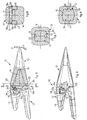
- the reference number 10 denotes the tooth according to the invention for buckets 11 of excavators or similar equipment.
- Said tooth 10 comprises a point-bearer 12, able to be attached in a known manner to the lower side 11a of the bucket 11, and a point 13 able to be associated due to their coupling shape at the front of the point-bearer 12 and able to be clamped on the latter by means of a pin 17.
- the point-bearer 12 defines in a single piece a main body 14, at the rear, able to be positioned above the lower side 11a of the bucket 11, and a front protrusion 15, wedge-shaped, able to be inserted in a cavity 16, of mating shape, made on the rear of the point 13, interfering with the inner surface of the cavity 16.
- the front protrusion 15 has a substantially hexagonal transverse section, with two lateral grooves 23.
- the front protrusion 15 has a substantially square transverse section, with two grooves 23 respectively on the upper and lower face.
- the pin 17 is advantageously axially hollow,and has a longitudinal cut 17a which allows a partial elastic deformation of the section.
- the lateral walls 18 of said cavity 16 extend beyond the latter, defining two protruding fins, or appendixes, 19; said fins 19, in the condition wherein the front protrusion 15 is inserted in said cavity 16, are able to house in corresponding recesses 22 of the main body 14, so as to overlap with the latter.
- the fins 19, substantially configured as a prism with a trapezoid base have at the upper part respective hollows 19a of a width substantially equivalent to the diameter of the pin 17; said hollows 19a are able to align with a through hole 21, made transversely in correspondence with the recesses 22 of the main body 14, and of a diameter substantially equivalent to that of the pin 17, in order to define therewith a housing seating 20 for the pin 17.
- the hollows 19a have the relative axis slightly off-center, towards the front protrusion 15, with respect to the axis of the hole 21; for this reason, the insertion of the pin 17 into the seating 20 draws the point 13 on the point-bearer 12, determining a further penetration of the front protrusion 15 into the cavity 16 and hence an increase in interference between the two, making the clamping of the point-bearer 12 and point 13 more stable and secure.
- first slit 24 of a width in the range of some tenths of a millimeter
- second slit 26 of a slightly greater width
- the fins 19 instead of the hollows 19a the fins 19 have respective through eyelets 19b, which have the same function; said through eyelets 19b are arranged substantially vertical and are able to align with a hole 21 made in a more central position on the main body 14 of the point-bearer 12.
- the load "P" weighing on the front part of the point 13 determines a moment which tends to make the point 13 rotate with respect to the point-bearer 12, in the direction of the arrow indicated by the letter “R” ( figs. 3 and 5 ), taking the upper profile 19c of the fins 19 to abut on the upper edge 22a of the recesses 22, so as to discharge at least a part of the stresses deriving from the load "P" on the main body 14.
- the lower edge 19d of the hollow 19a approaches the pin 17, but without coming into contact with it, so that the same pin 17 is not substantially affected by the shearing forces deriving from the load "P", thus considerably reducing the risks of breakages.
- the tooth 10 according to the invention therefore allows a better distribution on the point-bearer 12 of the stresses deriving from the load "P" weighing on the point 13, limiting the forces affecting the pin 17.
- the front protrusion 15 could have a rhomboid or pentagonal section, or otherwise.
- the pin 17 could be of a different type with respect to the one shown here.
Claims (15)
- Dent pour godet (11) de pelle mécanique, ou machine similaire, comprenant un élément de travail (13) pouvant être associé à un élément de support correspondant (12), dans lequel ledit élément de support (12) comporte un corps principal (14) grâce auquel il peut être fixé audit godet (11), et une partie avant saillante (15) pouvant être insérée dans une cavité d'assemblage (16) située à l'arrière dudit élément de travail (13), de manière à définir une condition d'assemblage entre ledit élément de travail (13) et ledit élément de support (12), et dans lequel des tiges (17) peuvent être insérées à la fois dans ledit élément de support (12) et dans ledit élément de travail (13), de manière à attacher mutuellement ledit élément de travail (13) audit élément de support (12) dans ladite condition d'assemblage, dans lequel ledit élément de travail (13) comprend au moins un élément faisant saillie (19) depuis l'arrière par rapport à ladite cavité (16) et pouvant être couplé audit corps principal (14) au moyen d'une encoche d'assemblage (22) définissant au moins un bord supérieur correspondant (22a) et dans lequel un élément de logement (20) pour lesdites tiges (17) est formé en partie dans ledit élément (19) et en partie dans ledit corps principal (14), caractérisé en ce que, dans ladite condition d'assemblage, une première fente (24) est située entre le profil supérieur (19c) dudit élément (19) et le bord supérieur (22a).
- Dent selon la revendication 1, caractérisée en ce que ledit élément de travail (13) comprend deux éléments (19) disposés de façon sensiblement symétrique autour d'un axe longitudinal médian de ce dernier.
- Dent selon la revendication 1 ou 2, caractérisée en ce que chacun des éléments (19) est défini par une extension d'au moins une paroi latérale (18) de ladite cavité (16).
- Dent selon l'une quelconque des revendications précédentes, dans laquelle ladite cavité (16) est délimitée dans sa partie inférieure par une paroi inférieure (25), caractérisée en ce que, dans ladite condition d'assemblage, entre le segment inférieur (14a) dudit corps principal (14) et ladite paroi inférieure (25) se trouve une seconde fente (26) dont la largeur est plus importante que celle de celle de ladite première fente (24).
- Dent selon l'une quelconque des revendications précédentes, caractérisée en ce que lesdits éléments (19) forment sensiblement un prisme à base trapézoïdale.
- Dent selon l'une quelconque des revendications précédentes, caractérisée en ce que ledit élément de logement (20) est défini par un orifice de passage (21), formé sur ledit corps principal (14) et doté d'une partie s'assemblant avec lesdites tiges (17), et par une ouverture (19a, 19b), formée sur chacun desdits éléments (19), pouvant être mise en relation avec ledit orifice de passage (21).
- Dent selon la revendication 6, caractérisée en ce que, entre lesdites tiges (17) insérées dans ledit élément de logement (20) et le bord inférieur (19d) de ladite ouverture (19a, 19b) se trouve un espace (27) dont l'amplitude est supérieure à la largeur de ladite première fente (24).
- Dent selon la revendication 6, caractérisée en ce que, dans ladite condition d'assemblage et avec lesdites tiges (17) sorties dudit élément de logement (20), ladite ouverture (19a, 19b) est légèrement excentrée, en direction de ladite partie avant saillante (15) par rapport audit orifice de passage (21), l'insertion desdites tiges (17) dans ledit élément de logement (20) déterminant l'alignement de ladite ouverture (19a, 19b) et dudit orifice de passage (21), et une nouvelle pénétration de ladite partie avant saillante (15) dans ladite cavité (16).
- Dent selon l'une quelconque des revendications précédentes, caractérisée en ce que ladite ouverture consiste en une partie creuse (19a) dudit élément (19).
- Dent selon l'une quelconque des revendications 1 à 8 incluse, caractérisée en ce que ladite ouverture consiste en un oeillet (19b) présent sur ledit élément (19).
- Dent selon l'une quelconque des revendications précédentes, caractérisée en ce que ladite partie avant saillante (15) comprend une partie transversale sensiblement polygonale.
- Dent selon l'une quelconque des revendications précédentes, caractérisée en ce que ladite partie avant saillante (15) comprend une partie transversale se rétrécissant depuis son extrémité arrière, dans la direction dudit corps principal (14), jusqu'à son extrémité avant.
- Dent selon l'une quelconque des revendications précédentes, caractérisée en ce que ladite partie avant saillante (15) comprend au moins une rainure longitudinale (23) sur l'une de ses faces.
- Dent selon l'une quelconque des revendications précédentes, caractérisée en ce que lesdites tiges (17) comprennent une partie élastiquement déformable au moins en partie.
- Dans selon la revendication 14, caractérisée en ce que lesdites tiges (17) sont creuses sur toute leur longueur et sont dotées d'une rainure de passage longitudinale (17a).
Priority Applications (1)
| Application Number | Priority Date | Filing Date | Title |
|---|---|---|---|
| PL05702423T PL1718809T3 (pl) | 2004-02-10 | 2005-02-04 | Ząb do łyżki w koparce lub podobnym urządzeniu, składający się z ostro zakończonego elementu, nazywanego także końcówką oraz dodatkowych elementów wspomagających lub nośnika końcówki, połączonych razem ze sobą za pomocą bolca |
Applications Claiming Priority (2)
| Application Number | Priority Date | Filing Date | Title |
|---|---|---|---|
| IT000021A ITUD20040021A1 (it) | 2004-02-10 | 2004-02-10 | Dente per benne di escavatori o simili |
| PCT/IB2005/000277 WO2005080695A1 (fr) | 2004-02-10 | 2005-02-04 | Dent pour godet de pelle mecanique |
Publications (2)
| Publication Number | Publication Date |
|---|---|
| EP1718809A1 EP1718809A1 (fr) | 2006-11-08 |
| EP1718809B1 true EP1718809B1 (fr) | 2008-10-01 |
Family
ID=34878881
Family Applications (1)
| Application Number | Title | Priority Date | Filing Date |
|---|---|---|---|
| EP05702423A Not-in-force EP1718809B1 (fr) | 2004-02-10 | 2005-02-04 | Dent pour godet de pelle mecanique. |
Country Status (8)
| Country | Link |
|---|---|
| US (1) | US20070256335A1 (fr) |
| EP (1) | EP1718809B1 (fr) |
| AT (1) | ATE409782T1 (fr) |
| DE (1) | DE602005010051D1 (fr) |
| ES (1) | ES2317185T3 (fr) |
| IT (1) | ITUD20040021A1 (fr) |
| PL (1) | PL1718809T3 (fr) |
| WO (1) | WO2005080695A1 (fr) |
Cited By (1)
| Publication number | Priority date | Publication date | Assignee | Title |
|---|---|---|---|---|
| CN102308050A (zh) * | 2009-02-06 | 2012-01-04 | 麦塔洛吉尼亚股份有限公司 | 用于连接挖掘机和类似机器的磨损元件与适配器的连接系统及其部件 |
Families Citing this family (18)
| Publication number | Priority date | Publication date | Assignee | Title |
|---|---|---|---|---|
| PL3249120T3 (pl) | 2006-03-30 | 2022-01-17 | Esco Group Llc | Zespół zużywalny |
| SI2889434T1 (sl) * | 2007-05-10 | 2019-06-28 | Esco Group Llc | Člen za obrabo in sklop za obrabo za opremo za izkopavanje |
| AU2013205251C1 (en) * | 2009-12-11 | 2020-01-23 | Cqms Pty Ltd | A lock assembly for an excavator wear member |
| CA2783698C (fr) * | 2009-12-11 | 2019-12-03 | Cqms Pty Ltd | Ensemble de verrouillage pour element d'usure d'excavatrice |
| US10011977B2 (en) | 2011-09-08 | 2018-07-03 | Miguel Guimaraes | Lock assembly for an excavator wear member |
| US8943717B2 (en) | 2011-10-08 | 2015-02-03 | Caterpillar Inc. | Implement tooth assembly with tip and adapter |
| US9062436B2 (en) | 2011-10-07 | 2015-06-23 | Caterpillar Inc. | Implement tooth assembly with tip and adapter |
| US9057177B2 (en) | 2011-10-08 | 2015-06-16 | Caterpillar Inc. | Implement tooth assembly with tip and adapter |
| US8943716B2 (en) | 2011-10-10 | 2015-02-03 | Caterpillar Inc. | Implement tooth assembly with tip and adapter |
| IN2014KN01273A (fr) | 2011-12-08 | 2015-10-16 | Cqms Pty Ltd | |
| US9441351B2 (en) * | 2013-08-01 | 2016-09-13 | Caterpillar Inc. | Ground engaging tool assembly |
| US9290914B2 (en) | 2013-08-01 | 2016-03-22 | Caterpillar Inc. | Ground engaging tool assembly |
| US9441349B2 (en) * | 2013-08-01 | 2016-09-13 | Caterpillar Inc. | Ground engaging tool assembly |
| US9273448B2 (en) * | 2013-08-01 | 2016-03-01 | Caterpillar Inc. | Ground engaging tool assembly |
| GB2532335B (en) * | 2014-10-02 | 2017-03-29 | Pearson Eng Ltd | Improvements in or relating to ploughing tines |
| JP6454780B2 (ja) * | 2015-02-13 | 2019-01-16 | ブラック、キャット、ブレイズ、リミテッドBlack Cat Blades Ltd. | 掘削器具用摩耗部材 |
| USD779566S1 (en) | 2015-10-02 | 2017-02-21 | Pearson Engineering Limited | Plowing tine replacement section |
| USD800798S1 (en) | 2015-10-02 | 2017-10-24 | Pearson Engineering Limited | Plowing tine tip |
Family Cites Families (51)
| Publication number | Priority date | Publication date | Assignee | Title |
|---|---|---|---|---|
| US1571782A (en) * | 1925-02-14 | 1926-02-02 | Taylor Wharton Iron & Steel | Dipper tooth |
| US1856930A (en) * | 1929-12-16 | 1932-05-03 | Wellman Engineering Company | Dipper tooth structure |
| US3325926A (en) * | 1964-03-09 | 1967-06-20 | Mid Continent Steel Casting Co | Digger tooth and assembly for an excavating apparatus |
| US3371437A (en) * | 1965-04-28 | 1968-03-05 | Mid Continent Steel Casting Co | Locking device for digger tooth |
| US3444633A (en) * | 1966-09-06 | 1969-05-20 | Hensley Equipment Co Inc | Two-part excavating tooth |
| US3601911A (en) * | 1969-08-25 | 1971-08-31 | Concrete Steel Corp | Replaceable fork tine wear tip |
| DE2211768A1 (de) * | 1971-03-18 | 1972-10-05 | Italsider Spa | Verbindungsvorrichtung für Baggeroder Ripperzähne, besonders für zweiteilige Bagger |
| US3851413A (en) * | 1971-08-23 | 1974-12-03 | Caterpillar Tractor Co | Quick change cutting edge |
| US3812608A (en) * | 1971-12-06 | 1974-05-28 | Abex Corp | Dipper bucket corner member with integral shroud |
| IT1027392B (it) * | 1975-01-28 | 1978-11-20 | Ramella P V | Dente per benne di macchine per movimento terra |
| USD251431S (en) * | 1976-12-16 | 1979-03-27 | Caterpillar Tractor Co. | Tooth adapter for a cutting edge |
| FR2381137A1 (fr) * | 1977-02-18 | 1978-09-15 | Esco Corp | Dent excavatrice pour godet de chargeuse sur pneumatiques ou analogue |
| USD252461S (en) * | 1977-03-08 | 1979-07-24 | Aktiebolaget Bofors | Tooth adaptor for excavating equipment |
| US6735890B2 (en) * | 2001-07-06 | 2004-05-18 | Esco Corporation | Wear assembly |
| USD251667S (en) * | 1977-11-09 | 1979-04-24 | Corona Clipper Company | Digger tooth |
| US4338736A (en) * | 1981-03-06 | 1982-07-13 | Caterpillar Tractor Co. | Retaining pin assembly for earthworking tool |
| SE445125B (sv) * | 1981-03-26 | 1986-06-02 | Bofors Ab | Slitdelssystem for jordbearbetningsmaskiner |
| USD274434S (en) * | 1981-11-23 | 1984-06-26 | Aktiebolaget Bofors | Loader tooth adapters for corner assembly |
| USD297643S (en) * | 1985-09-16 | 1988-09-13 | Ab Bofors Wear Parts | Loader tooth for earth moving machines |
| USD339593S (en) * | 1990-04-03 | 1993-09-21 | Components Tools AB | Tooth point |
| USD336304S (en) * | 1990-08-24 | 1993-06-08 | G. H. Hensley Industries, Inc. | Excavator tooth |
| USD336476S (en) * | 1991-08-30 | 1993-06-15 | Caterpillar Inc. | Adapter for an implement |
| US5469648A (en) * | 1993-02-02 | 1995-11-28 | Esco Corporation | Excavating tooth |
| US5386653A (en) * | 1993-06-01 | 1995-02-07 | Caterpillar Inc. | Tooth to adapter interface |
| US5456029A (en) * | 1993-11-01 | 1995-10-10 | Caterpillar Inc. | Tooth to adapter coupler |
| US5423138A (en) * | 1994-04-04 | 1995-06-13 | Caterpillar, Inc. | Tip to adapter interface |
| US5561925A (en) * | 1995-07-25 | 1996-10-08 | Caterpillar Inc. | Tooth assembly and retaining mechanism |
| US5782019A (en) * | 1995-11-29 | 1998-07-21 | H & L Tooth Company | High strength earth working tooth |
| US5709043A (en) * | 1995-12-11 | 1998-01-20 | Esco Corporation | Excavating tooth |
| USD395661S (en) * | 1995-12-14 | 1998-06-30 | Metalogenia S.A. | Digger tooth |
| USD389844S (en) * | 1995-12-14 | 1998-01-27 | Metalogenia, S.A. | Digger tooth |
| USD385286S (en) * | 1996-05-09 | 1997-10-21 | Metalogenia, S.A. | Digger tooth Series K |
| EP0835963B1 (fr) * | 1996-07-01 | 1999-09-15 | Metalogenia, S.A. | Joint d'accouplement pour dent d'excavatrice |
| USD410657S (en) * | 1997-09-03 | 1999-06-08 | H&L Tooth Company | Grooved earth working tool |
| USD417877S (en) * | 1997-09-08 | 1999-12-21 | H&L Tooth Company | Digging tooth |
| US5937551A (en) * | 1997-11-07 | 1999-08-17 | Columbia Steel Casting Co., Inc. | Lock system for excavating tooth point and adapter |
| USD420014S (en) * | 1998-03-02 | 2000-02-01 | Componenta Wear Parts Ab | Tooth system |
| US5956874A (en) * | 1998-05-07 | 1999-09-28 | Columbia Steel Casting Co., Inc. | Tooth assembly and lock system |
| ES2146541B1 (es) * | 1998-06-08 | 2001-04-01 | Metalogenia Sa | Dispositivo para el acoplamiento de dientes de excavadoras. |
| ES2146174B1 (es) * | 1998-07-03 | 2002-01-16 | Metalogenia Sa | Acoplamiento para dientes de excavadoras y similares. |
| USD413338S (en) * | 1998-09-28 | 1999-08-31 | Metalogenia, S.A. | Tooth for an excavating machine |
| USD429256S (en) * | 1999-06-14 | 2000-08-08 | Deere & Company | Tillage sweep |
| ES2158805B1 (es) * | 1999-10-01 | 2002-04-01 | Metalogenia Sa | Perfeccionamientos en los acoplamientos para dientes de maquinas para movimiento de tierras. |
| USD435567S (en) * | 1999-10-21 | 2000-12-26 | H&L Tooth Co. | Digging tooth |
| USD436116S1 (en) * | 1999-10-21 | 2001-01-09 | H&L Tooth Co. | Digging tooth |
| US6477796B1 (en) * | 2000-07-06 | 2002-11-12 | Caterpillar Inc | Tooth assembly for implements |
| US6240663B1 (en) * | 2000-09-18 | 2001-06-05 | G. H. Hensley Industries, Incorporated | Streamlined resilient connection system for attaching a wear member to an excavating lip structure |
| ES2168988B1 (es) * | 2000-10-03 | 2003-12-01 | Metalogenia Sa | Sistema de acoplamiento para los dientes de una excavadora. |
| CA97589S (en) * | 2001-04-02 | 2003-06-19 | Volvo Constr Equip Holding Se | Tooth body and tooth carrier assembly |
| US6766602B2 (en) * | 2002-08-08 | 2004-07-27 | Caterpillar Inc. | Corner tooth adapter arrangement for an excavating implement |
| USD499749S1 (en) * | 2003-10-14 | 2004-12-14 | H&L Tooth Company | Ground engaging tooth |
-
2004
- 2004-02-10 IT IT000021A patent/ITUD20040021A1/it unknown
-
2005
- 2005-02-04 WO PCT/IB2005/000277 patent/WO2005080695A1/fr active IP Right Grant
- 2005-02-04 DE DE602005010051T patent/DE602005010051D1/de active Active
- 2005-02-04 PL PL05702423T patent/PL1718809T3/pl unknown
- 2005-02-04 US US10/597,831 patent/US20070256335A1/en not_active Abandoned
- 2005-02-04 EP EP05702423A patent/EP1718809B1/fr not_active Not-in-force
- 2005-02-04 AT AT05702423T patent/ATE409782T1/de not_active IP Right Cessation
- 2005-02-04 ES ES05702423T patent/ES2317185T3/es active Active
Cited By (2)
| Publication number | Priority date | Publication date | Assignee | Title |
|---|---|---|---|---|
| CN102308050A (zh) * | 2009-02-06 | 2012-01-04 | 麦塔洛吉尼亚股份有限公司 | 用于连接挖掘机和类似机器的磨损元件与适配器的连接系统及其部件 |
| CN102308050B (zh) * | 2009-02-06 | 2014-11-19 | 麦塔洛吉尼亚股份有限公司 | 用于连接挖掘机和类似机器的磨损元件与适配器的连接系统及其部件 |
Also Published As
| Publication number | Publication date |
|---|---|
| WO2005080695A1 (fr) | 2005-09-01 |
| DE602005010051D1 (de) | 2008-11-13 |
| US20070256335A1 (en) | 2007-11-08 |
| PL1718809T3 (pl) | 2009-04-30 |
| ATE409782T1 (de) | 2008-10-15 |
| ITUD20040021A1 (it) | 2004-05-10 |
| EP1718809A1 (fr) | 2006-11-08 |
| ES2317185T3 (es) | 2009-04-16 |
Similar Documents
| Publication | Publication Date | Title |
|---|---|---|
| EP1718809B1 (fr) | Dent pour godet de pelle mecanique. | |
| CA2336125C (fr) | Accouplement de dents d'excavateurs et similaires | |
| CA2333387C (fr) | Dispositif pour l'accouplement de dents d'excavateur | |
| KR100632911B1 (ko) | 다품식 굴착용 톱니 조립체 | |
| US6477796B1 (en) | Tooth assembly for implements | |
| AU2006284993B2 (en) | Wear assembly for excavating machines | |
| US4043060A (en) | Combination strengthened loader bucket and replaceable cutting edge | |
| US6079132A (en) | Excavating tooth assembly | |
| US20220243429A1 (en) | Implement ground engaging tip assembly having tip with tapered retention channel | |
| US20050055853A1 (en) | Mechanically attached tip assembly | |
| AU2017378397B2 (en) | Implement tip assembly having tip with support rib | |
| EP2571343B1 (fr) | Pointe d'extrémité pour outil de travail du sol | |
| US5224282A (en) | Tooth assembly for a digger bucket | |
| JP2007009631A (ja) | バケット | |
| CA2967892A1 (fr) | Element de guidage ou combinaison d'outils pourvu d'un element de guidage | |
| JP4882121B2 (ja) | ショベル系掘削機用ツース部材及びそのバケット | |
| US20200048872A1 (en) | Implement tip assembly having tip with wear indicator | |
| US4601119A (en) | Corner tooth for a bucket | |
| US20140131494A1 (en) | Device For Crushing And/Or Cutting Material, As Well As A Piercing Element, Suitable For Mounting To The Free Nose End Of A Mouth Of Such A Device | |
| JPH042220Y2 (fr) | ||
| RU182156U1 (ru) | Узел зуба ковша экскаватора | |
| JP5877430B1 (ja) | ツース盤 | |
| CZ20004810A3 (cs) | Spřáhlo pro zuby rýpadel a podobných zařízení | |
| MXPA00012747A (en) | Coupling for excavator teeth and the like |
Legal Events
| Date | Code | Title | Description |
|---|---|---|---|
| PUAI | Public reference made under article 153(3) epc to a published international application that has entered the european phase |
Free format text: ORIGINAL CODE: 0009012 |
|
| 17P | Request for examination filed |
Effective date: 20060905 |
|
| AK | Designated contracting states |
Kind code of ref document: A1 Designated state(s): AT BE BG CH CY CZ DE DK EE ES FI FR GB GR HU IE IS IT LI LT LU MC NL PL PT RO SE SI SK TR |
|
| DAX | Request for extension of the european patent (deleted) | ||
| GRAP | Despatch of communication of intention to grant a patent |
Free format text: ORIGINAL CODE: EPIDOSNIGR1 |
|
| GRAS | Grant fee paid |
Free format text: ORIGINAL CODE: EPIDOSNIGR3 |
|
| GRAA | (expected) grant |
Free format text: ORIGINAL CODE: 0009210 |
|
| AK | Designated contracting states |
Kind code of ref document: B1 Designated state(s): AT BE BG CH CY CZ DE DK EE ES FI FR GB GR HU IE IS IT LI LT LU MC NL PL PT RO SE SI SK TR |
|
| REG | Reference to a national code |
Ref country code: GB Ref legal event code: FG4D |
|
| REG | Reference to a national code |
Ref country code: CH Ref legal event code: EP |
|
| REG | Reference to a national code |
Ref country code: IE Ref legal event code: FG4D |
|
| REF | Corresponds to: |
Ref document number: 602005010051 Country of ref document: DE Date of ref document: 20081113 Kind code of ref document: P |
|
| PG25 | Lapsed in a contracting state [announced via postgrant information from national office to epo] |
Ref country code: SI Free format text: LAPSE BECAUSE OF FAILURE TO SUBMIT A TRANSLATION OF THE DESCRIPTION OR TO PAY THE FEE WITHIN THE PRESCRIBED TIME-LIMIT Effective date: 20081001 |
|
| NLV1 | Nl: lapsed or annulled due to failure to fulfill the requirements of art. 29p and 29m of the patents act | ||
| REG | Reference to a national code |
Ref country code: ES Ref legal event code: FG2A Ref document number: 2317185 Country of ref document: ES Kind code of ref document: T3 |
|
| PG25 | Lapsed in a contracting state [announced via postgrant information from national office to epo] |
Ref country code: BG Free format text: LAPSE BECAUSE OF FAILURE TO SUBMIT A TRANSLATION OF THE DESCRIPTION OR TO PAY THE FEE WITHIN THE PRESCRIBED TIME-LIMIT Effective date: 20090101 Ref country code: AT Free format text: LAPSE BECAUSE OF FAILURE TO SUBMIT A TRANSLATION OF THE DESCRIPTION OR TO PAY THE FEE WITHIN THE PRESCRIBED TIME-LIMIT Effective date: 20081001 Ref country code: LT Free format text: LAPSE BECAUSE OF FAILURE TO SUBMIT A TRANSLATION OF THE DESCRIPTION OR TO PAY THE FEE WITHIN THE PRESCRIBED TIME-LIMIT Effective date: 20081001 |
|
| REG | Reference to a national code |
Ref country code: PL Ref legal event code: T3 |
|
| PG25 | Lapsed in a contracting state [announced via postgrant information from national office to epo] |
Ref country code: NL Free format text: LAPSE BECAUSE OF FAILURE TO SUBMIT A TRANSLATION OF THE DESCRIPTION OR TO PAY THE FEE WITHIN THE PRESCRIBED TIME-LIMIT Effective date: 20081001 Ref country code: PT Free format text: LAPSE BECAUSE OF FAILURE TO SUBMIT A TRANSLATION OF THE DESCRIPTION OR TO PAY THE FEE WITHIN THE PRESCRIBED TIME-LIMIT Effective date: 20090302 Ref country code: FI Free format text: LAPSE BECAUSE OF FAILURE TO SUBMIT A TRANSLATION OF THE DESCRIPTION OR TO PAY THE FEE WITHIN THE PRESCRIBED TIME-LIMIT Effective date: 20081001 Ref country code: IS Free format text: LAPSE BECAUSE OF FAILURE TO SUBMIT A TRANSLATION OF THE DESCRIPTION OR TO PAY THE FEE WITHIN THE PRESCRIBED TIME-LIMIT Effective date: 20090201 |
|
| PG25 | Lapsed in a contracting state [announced via postgrant information from national office to epo] |
Ref country code: EE Free format text: LAPSE BECAUSE OF FAILURE TO SUBMIT A TRANSLATION OF THE DESCRIPTION OR TO PAY THE FEE WITHIN THE PRESCRIBED TIME-LIMIT Effective date: 20081001 Ref country code: RO Free format text: LAPSE BECAUSE OF FAILURE TO SUBMIT A TRANSLATION OF THE DESCRIPTION OR TO PAY THE FEE WITHIN THE PRESCRIBED TIME-LIMIT Effective date: 20081001 Ref country code: DK Free format text: LAPSE BECAUSE OF FAILURE TO SUBMIT A TRANSLATION OF THE DESCRIPTION OR TO PAY THE FEE WITHIN THE PRESCRIBED TIME-LIMIT Effective date: 20081001 |
|
| PLBE | No opposition filed within time limit |
Free format text: ORIGINAL CODE: 0009261 |
|
| STAA | Information on the status of an ep patent application or granted ep patent |
Free format text: STATUS: NO OPPOSITION FILED WITHIN TIME LIMIT |
|
| PG25 | Lapsed in a contracting state [announced via postgrant information from national office to epo] |
Ref country code: SE Free format text: LAPSE BECAUSE OF FAILURE TO SUBMIT A TRANSLATION OF THE DESCRIPTION OR TO PAY THE FEE WITHIN THE PRESCRIBED TIME-LIMIT Effective date: 20090101 |
|
| 26N | No opposition filed |
Effective date: 20090702 |
|
| PG25 | Lapsed in a contracting state [announced via postgrant information from national office to epo] |
Ref country code: SK Free format text: LAPSE BECAUSE OF FAILURE TO SUBMIT A TRANSLATION OF THE DESCRIPTION OR TO PAY THE FEE WITHIN THE PRESCRIBED TIME-LIMIT Effective date: 20081001 Ref country code: MC Free format text: LAPSE BECAUSE OF NON-PAYMENT OF DUE FEES Effective date: 20090228 |
|
| REG | Reference to a national code |
Ref country code: CH Ref legal event code: PL |
|
| PG25 | Lapsed in a contracting state [announced via postgrant information from national office to epo] |
Ref country code: LI Free format text: LAPSE BECAUSE OF NON-PAYMENT OF DUE FEES Effective date: 20090228 Ref country code: CH Free format text: LAPSE BECAUSE OF NON-PAYMENT OF DUE FEES Effective date: 20090228 |
|
| PG25 | Lapsed in a contracting state [announced via postgrant information from national office to epo] |
Ref country code: IE Free format text: LAPSE BECAUSE OF NON-PAYMENT OF DUE FEES Effective date: 20090204 |
|
| PG25 | Lapsed in a contracting state [announced via postgrant information from national office to epo] |
Ref country code: GR Free format text: LAPSE BECAUSE OF FAILURE TO SUBMIT A TRANSLATION OF THE DESCRIPTION OR TO PAY THE FEE WITHIN THE PRESCRIBED TIME-LIMIT Effective date: 20090102 |
|
| PG25 | Lapsed in a contracting state [announced via postgrant information from national office to epo] |
Ref country code: LU Free format text: LAPSE BECAUSE OF NON-PAYMENT OF DUE FEES Effective date: 20090204 |
|
| PGFP | Annual fee paid to national office [announced via postgrant information from national office to epo] |
Ref country code: CZ Payment date: 20110201 Year of fee payment: 7 Ref country code: PL Payment date: 20110201 Year of fee payment: 7 |
|
| PG25 | Lapsed in a contracting state [announced via postgrant information from national office to epo] |
Ref country code: HU Free format text: LAPSE BECAUSE OF FAILURE TO SUBMIT A TRANSLATION OF THE DESCRIPTION OR TO PAY THE FEE WITHIN THE PRESCRIBED TIME-LIMIT Effective date: 20090402 |
|
| PG25 | Lapsed in a contracting state [announced via postgrant information from national office to epo] |
Ref country code: CY Free format text: LAPSE BECAUSE OF FAILURE TO SUBMIT A TRANSLATION OF THE DESCRIPTION OR TO PAY THE FEE WITHIN THE PRESCRIBED TIME-LIMIT Effective date: 20081001 |
|
| PGFP | Annual fee paid to national office [announced via postgrant information from national office to epo] |
Ref country code: FR Payment date: 20120227 Year of fee payment: 8 |
|
| PGFP | Annual fee paid to national office [announced via postgrant information from national office to epo] |
Ref country code: TR Payment date: 20120201 Year of fee payment: 8 Ref country code: DE Payment date: 20120221 Year of fee payment: 8 |
|
| PGFP | Annual fee paid to national office [announced via postgrant information from national office to epo] |
Ref country code: BE Payment date: 20120329 Year of fee payment: 8 Ref country code: GB Payment date: 20120222 Year of fee payment: 8 Ref country code: IT Payment date: 20120217 Year of fee payment: 8 |
|
| PGFP | Annual fee paid to national office [announced via postgrant information from national office to epo] |
Ref country code: ES Payment date: 20120224 Year of fee payment: 8 |
|
| BERE | Be: lapsed |
Owner name: ITALRICAMBI S.P.A. Effective date: 20130228 |
|
| GBPC | Gb: european patent ceased through non-payment of renewal fee |
Effective date: 20130204 |
|
| PG25 | Lapsed in a contracting state [announced via postgrant information from national office to epo] |
Ref country code: CZ Free format text: LAPSE BECAUSE OF NON-PAYMENT OF DUE FEES Effective date: 20130204 |
|
| REG | Reference to a national code |
Ref country code: FR Ref legal event code: ST Effective date: 20131031 |
|
| REG | Reference to a national code |
Ref country code: DE Ref legal event code: R119 Ref document number: 602005010051 Country of ref document: DE Effective date: 20130903 |
|
| PG25 | Lapsed in a contracting state [announced via postgrant information from national office to epo] |
Ref country code: IT Free format text: LAPSE BECAUSE OF NON-PAYMENT OF DUE FEES Effective date: 20130204 |
|
| PG25 | Lapsed in a contracting state [announced via postgrant information from national office to epo] |
Ref country code: BE Free format text: LAPSE BECAUSE OF NON-PAYMENT OF DUE FEES Effective date: 20130228 Ref country code: FR Free format text: LAPSE BECAUSE OF NON-PAYMENT OF DUE FEES Effective date: 20130228 Ref country code: DE Free format text: LAPSE BECAUSE OF NON-PAYMENT OF DUE FEES Effective date: 20130903 Ref country code: GB Free format text: LAPSE BECAUSE OF NON-PAYMENT OF DUE FEES Effective date: 20130204 |
|
| REG | Reference to a national code |
Ref country code: ES Ref legal event code: FD2A Effective date: 20140409 |
|
| PG25 | Lapsed in a contracting state [announced via postgrant information from national office to epo] |
Ref country code: PL Free format text: LAPSE BECAUSE OF NON-PAYMENT OF DUE FEES Effective date: 20130204 |
|
| REG | Reference to a national code |
Ref country code: PL Ref legal event code: LAPE |
|
| PG25 | Lapsed in a contracting state [announced via postgrant information from national office to epo] |
Ref country code: ES Free format text: LAPSE BECAUSE OF NON-PAYMENT OF DUE FEES Effective date: 20130205 |
|
| PG25 | Lapsed in a contracting state [announced via postgrant information from national office to epo] |
Ref country code: TR Free format text: LAPSE BECAUSE OF NON-PAYMENT OF DUE FEES Effective date: 20130204 |