EP2006988A1 - Inverter - Google Patents
Inverter Download PDFInfo
- Publication number
- EP2006988A1 EP2006988A1 EP07010195A EP07010195A EP2006988A1 EP 2006988 A1 EP2006988 A1 EP 2006988A1 EP 07010195 A EP07010195 A EP 07010195A EP 07010195 A EP07010195 A EP 07010195A EP 2006988 A1 EP2006988 A1 EP 2006988A1
- Authority
- EP
- European Patent Office
- Prior art keywords
- bracket
- inverter according
- housing chamber
- wall
- housing
- Prior art date
- Legal status (The legal status is an assumption and is not a legal conclusion. Google has not performed a legal analysis and makes no representation as to the accuracy of the status listed.)
- Granted
Links
Images


Classifications
-
- H—ELECTRICITY
- H02—GENERATION; CONVERSION OR DISTRIBUTION OF ELECTRIC POWER
- H02M—APPARATUS FOR CONVERSION BETWEEN AC AND AC, BETWEEN AC AND DC, OR BETWEEN DC AND DC, AND FOR USE WITH MAINS OR SIMILAR POWER SUPPLY SYSTEMS; CONVERSION OF DC OR AC INPUT POWER INTO SURGE OUTPUT POWER; CONTROL OR REGULATION THEREOF
- H02M7/00—Conversion of ac power input into dc power output; Conversion of dc power input into ac power output
- H02M7/003—Constructional details, e.g. physical layout, assembly, wiring or busbar connections
-
- H—ELECTRICITY
- H05—ELECTRIC TECHNIQUES NOT OTHERWISE PROVIDED FOR
- H05K—PRINTED CIRCUITS; CASINGS OR CONSTRUCTIONAL DETAILS OF ELECTRIC APPARATUS; MANUFACTURE OF ASSEMBLAGES OF ELECTRICAL COMPONENTS
- H05K5/00—Casings, cabinets or drawers for electric apparatus
- H05K5/04—Metal casings
-
- H—ELECTRICITY
- H02—GENERATION; CONVERSION OR DISTRIBUTION OF ELECTRIC POWER
- H02M—APPARATUS FOR CONVERSION BETWEEN AC AND AC, BETWEEN AC AND DC, OR BETWEEN DC AND DC, AND FOR USE WITH MAINS OR SIMILAR POWER SUPPLY SYSTEMS; CONVERSION OF DC OR AC INPUT POWER INTO SURGE OUTPUT POWER; CONTROL OR REGULATION THEREOF
- H02M7/00—Conversion of ac power input into dc power output; Conversion of dc power input into ac power output
- H02M7/42—Conversion of dc power input into ac power output without possibility of reversal
- H02M7/44—Conversion of dc power input into ac power output without possibility of reversal by static converters
- H02M7/48—Conversion of dc power input into ac power output without possibility of reversal by static converters using discharge tubes with control electrode or semiconductor devices with control electrode
-
- Y—GENERAL TAGGING OF NEW TECHNOLOGICAL DEVELOPMENTS; GENERAL TAGGING OF CROSS-SECTIONAL TECHNOLOGIES SPANNING OVER SEVERAL SECTIONS OF THE IPC; TECHNICAL SUBJECTS COVERED BY FORMER USPC CROSS-REFERENCE ART COLLECTIONS [XRACs] AND DIGESTS
- Y02—TECHNOLOGIES OR APPLICATIONS FOR MITIGATION OR ADAPTATION AGAINST CLIMATE CHANGE
- Y02E—REDUCTION OF GREENHOUSE GAS [GHG] EMISSIONS, RELATED TO ENERGY GENERATION, TRANSMISSION OR DISTRIBUTION
- Y02E10/00—Energy generation through renewable energy sources
- Y02E10/50—Photovoltaic [PV] energy
- Y02E10/56—Power conversion systems, e.g. maximum power point trackers
Definitions
- the present invention relates to an inverter comprising a housing.
- Inverters serve in the use of alternative energy sources, such. As PV modules, to convert DC into AC.
- Such an inverter has a housing, wherein in the housing power electronic components are arranged. These power electronic components are to be protected against environmental influences, in particular moisture.
- Such an inverter includes not only power electronic components, but also, if necessary, a plurality of plugs or the like to connect this inverter AC and DC side. Often enough, such an inverter also has a communication unit, for example in the form of a display, which also has to be connected.
- Inverters are installed by the local electrician when installing PV systems. For installation, the housing is opened in known inverters so that the installer can gain access to the corresponding plug contacts. Since the installation of such inverters often happens outdoors, the power electronic components are exposed to environmental influences at least for the period of installation and installation.
- the housing of the inverter in which the power electronic components are housed, must have a high degree of protection, namely the IP65, to ensure that when using such an inverter in the outdoor area, the power electronic components actually against environmental influences, and here in particular, are protected from moisture.
- the power electronic components actually against environmental influences, and here in particular, are protected from moisture.
- parts of the power electronics will be damaged intentionally or unintentionally during connection work of the electrician to the inverter.
- Even with maintenance work on the PV system it is often enough that only the access to the individual connections must be ensured when z. B. PV modules must be disconnected from the inverter or AC side, a separation should be made. That is, access to the In the case of maintenance, power electronic components should be exclusively used by the manufacturer or persons authorized by him.
- the invention is based on the object to provide an inverter in which the power electronic components are not directly accessible only for connection work.
- the housing comprises at least two housing chambers, each of which can be closed by a separate cover. From this it is clear that the power electronic components of the inverter can be accommodated in a separate housing chamber, whereas the connector and the communication unit, for example in the form of a display, are housed in a second housing chamber, which is arranged separately next to the first housing chamber in the housing of the inverter , In this respect, it is also not necessary that the lid of the housing chamber is opened for connection work, which receives the power electronic components.
- the first housing chamber receives the power electronic components, wherein in the first housing chamber of at least the second housing chamber at least one electrical connection is provided which has a class of protection at least that of the first housing chamber corresponds.
- the power electronic components in the first housing chamber are connected on the AC side and on the DC side to the second housing chamber in which the connection elements are located.
- the chamber accommodating the electronic power components must be protected against moisture in accordance with protection class IP65.
- the electrical connection between the first and the second housing chamber also has at least the degree of protection class possessed by the first housing chamber, in the present case, for example, at least protection class IP65.
- the electrical connection comprises a cable feedthrough.
- the first housing chamber which has the power electronic components, for connecting the cable to the network has a power terminal.
- the electrical connection comprises a socket, which is arranged in the wall to the first housing chamber, wherein the socket serves to receive a plug with the power cord.
- a feed-through terminal is provided as electrical connection, which is arranged in the wall to the first housing chamber.
- the formation of such a feedthrough terminal with protection class IP65 is also the subject of the invention.
- the lead-through terminal a Clamping body, wherein the clamp body has a shield for abutment against the wall of the first housing chamber, wherein the clamp body has a clamping member through which the clamp body is pressed with the shield to the wall of the housing chamber.
- the shield of the terminal body is used by the tendon during assembly to the wall, which is ensured by the required tightness in the region of the transition from the second chamber to the other first chamber.
- the shield has a peripheral seal, with which the plate rests against the wall.
- a clip which is displaceably receivable by the clamp body.
- the clip is formed in particular in the manner of a U-shaped bracket, wherein the leg of the bracket is formed in the side view of the bracket in the direction of the web of the bracket conically widening.
- the clamp body for the legs of the bracket has rail-like receptacles, wherein on the side facing away from the shield part of the rail-like receptacle each have a contact edge for the bracket is provided, wherein the abutment edge is formed obliquely corresponding to the formation of the legs of the bracket.
- the housing 1 of the inverter has the two chambers 2 and 3, wherein the first chamber 2 shows the power electronic components 4, which are merely indicated in the first housing chamber 2.
- the two housing chambers 2 and 3 are separated by the wall 5.
- the wall 5 has further connector elements 6 on the DC side, the connection with the PV modules to the power electronic Make components (not shown) in the chamber 2.
- a power cable 7 is provided, which is guided through the wall 5 from the second housing chamber 3 into the first housing chamber 2.
- the power terminal 8 which receives the individual strands of the cable 7.
- the cable bushing 10 through the wall 5 in this case has the protection class IP65, as well as the first housing chamber 2 is protected according to this class of protection against environmental influences, and in particular against moisture.
- the lid 2a which covers the first housing chamber 2 has a seal, so that the first housing chamber is to be classified in terms of protection against environmental influences of protection class IP65.
- the second lid 3a covers the housing chamber 3, wherein it should be noted as a special feature that the cover 2a shows tabs 2b, one of which serves to receive a screw 2c, which is screwed into the wall 5 from the top side and thus fixation of the Cover 2a on the first housing chamber 2 is used. It is essential that the lid 3 covers these tabs 2b with the screw 2c and so first the lid 3a must be removed before the housing chamber 2 can be opened. This provides added security to prevent the installer from inadvertently opening the first enclosure chamber when it is not necessary.
- FIG. 1 Assign cable bushing 10 to protection class IP65.
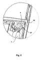
- FIG. 2 is provided as a variant of a connection of the power cord to the power electronics a female connector 20 in the wall 5, wherein the female connector 20 is also assigned to the protection class IP65.
- the designated 21 plug of the power cord 7 is received by the socket 20.
- FIG. 3 is as a further variant of a connection of the power cord to the power electronics in the wall 5, a feed-through terminal 30 is arranged, which on one side, ie the housing chamber 3 associated with terminals for the power cord 7. In the housing chamber 2 is then again a power terminal 8, which are received by the individual strands of the cable.
- the lead-in terminal 30 has the terminal body 31 and the shield 32 with the circumferential seal 33.
- the shield is the lead-through terminal 30 on the wall 5 between the two housing chambers 2 and 3 at.
- the clamp body 31 has rail-like receptacles 34 on both sides (FIG. FIG. 5 ) in the form of dovetail guides, wherein a contact edge 35 is provided in the region of the rail-like receptacle 34.
- the designated U-shaped bracket 40 ( FIG.
Abstract
Description
Die vorliegende Erfindung betrifft einen Wechselrichter, umfassend ein Gehäuse.The present invention relates to an inverter comprising a housing.
Wechselrichter dienen bei der Nutzung alternativer Energiequellen, wie z. B. PV-Modulen, dazu, Gleichstrom in Wechselstrom umzuwandeln. Ein solcher Wechselrichter weist ein Gehäuse auf, wobei in dem Gehäuse leistungselektronische Bauteile angeordnet sind. Diese leistungselektronischen Bauteile sind vor Umwelteinflüssen, insbesondere Feuchtigkeit, zu schützen. Ein solcher Wechselrichter umfasst nicht nur leistungselektronische Bauteile, sondern darüber hinaus gegebenenfalls eine Vielzahl von Steckern oder Ähnliches, um diesen Wechselrichter AC- und DC-seitig anzuschließen. Häufig genug besitzt ein solcher Wechselrichter auch eine Kommunikationseinheit, beispielsweise in Form eines Displays, die ebenfalls angeschlossen werden muss.Inverters serve in the use of alternative energy sources, such. As PV modules, to convert DC into AC. Such an inverter has a housing, wherein in the housing power electronic components are arranged. These power electronic components are to be protected against environmental influences, in particular moisture. Such an inverter includes not only power electronic components, but also, if necessary, a plurality of plugs or the like to connect this inverter AC and DC side. Often enough, such an inverter also has a communication unit, for example in the form of a display, which also has to be connected.
Wechselrichter werden bei der Montage von PV-Anlagen durch den vor Ort tätigen Elektroinstallateur installiert. Zur Installation wird bei bekannten Wechselrichtern das Gehäuse geöffnet, damit der Installateur sich Zugang zu den entsprechenden Steckkontakten verschaffen kann. Da die Montage derartiger Wechselrichter häufig im Freien geschieht, sind die leistungselektronischen Bauteile zumindest für den Zeitraum der Montage und der Installation Umwelteinflüssen ausgesetzt.Inverters are installed by the local electrician when installing PV systems. For installation, the housing is opened in known inverters so that the installer can gain access to the corresponding plug contacts. Since the installation of such inverters often happens outdoors, the power electronic components are exposed to environmental influences at least for the period of installation and installation.
Nun ist aber bekannt, dass das Gehäuse des Wechselrichters, in dem die leistungselektronischen Bauteile untergebracht sind, eine hohe Schutzartklasse aufweisen muss, nämlich die IP65, um zu gewährleisten, dass bei Einsatz eines solchen Wechselrichters im Außenbereich die leistungselektronischen Bauteile tatsächlich vor Umwelteinflüssen, und hier insbesondere, vor Feuchtigkeit geschützt sind. Darüber hinaus besteht die Gefahr, dass bei Anschlussarbeiten des Elektroinstallateurs an dem Wechselrichter absichtlich oder unabsichtlich Teile der Leistungselektronik beschädigt werden. Auch bei Wartungsarbeiten an der PV-Anlage ist es häufig genug so, dass lediglich der Zugang zu den einzelnen Steckverbindungen gewährleistet sein muss, wenn z. B. PV-Module vom Wechselrichter getrennt werden müssen oder aber AC-seitig eine Trennung vorgenommen werden soll. Das heißt, Zugang zu den leistungselektronischen Bauteilen sollen im Wartungsfall ausschließlich der Hersteller oder von ihm beauftragte Personen haben.Now, however, it is known that the housing of the inverter, in which the power electronic components are housed, must have a high degree of protection, namely the IP65, to ensure that when using such an inverter in the outdoor area, the power electronic components actually against environmental influences, and here in particular, are protected from moisture. In addition, there is a risk that parts of the power electronics will be damaged intentionally or unintentionally during connection work of the electrician to the inverter. Even with maintenance work on the PV system, it is often enough that only the access to the individual connections must be ensured when z. B. PV modules must be disconnected from the inverter or AC side, a separation should be made. That is, access to the In the case of maintenance, power electronic components should be exclusively used by the manufacturer or persons authorized by him.
Das heißt, der Erfindung liegt die Aufgabe zu Grunde, einen Wechselrichter zu schaffen, bei dem die leistungselektronischen Bauteile allein zu Anschlussarbeiten nicht unmittelbar zugänglich sind.That is, the invention is based on the object to provide an inverter in which the power electronic components are not directly accessible only for connection work.
Zur Lösung der Aufgabe wird insofern erfindungsgemäß vorgeschlagen, dass das Gehäuse mindestens zwei Gehäusekammern umfasst, die jeweils durch einen gesonderten Deckel verschließbar sind. Hieraus wird deutlich, dass die leistungselektronischen Bauteile des Wechselrichters in einer gesonderten Gehäusekammer untergebracht werden können, wohingegen die Anschlussstecker und die Kommunikationseinheit, beispielsweise in Form eines Displays, in einer zweiten Gehäusekammer untergebracht sind, die gesondert neben der ersten Gehäusekammer im Gehäuse des Wechselrichters angeordnet ist. Insofern ist es auch nicht erforderlich, dass für Anschlussarbeiten der Deckel der Gehäusekammer geöffnet wird, die die leistungselektronischen Bauteile aufnimmt.To solve the problem, the invention proposes that the housing comprises at least two housing chambers, each of which can be closed by a separate cover. From this it is clear that the power electronic components of the inverter can be accommodated in a separate housing chamber, whereas the connector and the communication unit, for example in the form of a display, are housed in a second housing chamber, which is arranged separately next to the first housing chamber in the housing of the inverter , In this respect, it is also not necessary that the lid of the housing chamber is opened for connection work, which receives the power electronic components.
Vorteilhafte Merkmale zu der Erfindung und besondere Ausführungsformen sind den Unteransprüchen zu entnehmen.Advantageous features of the invention and particular embodiments can be found in the dependent claims.
Im Einzelnen ist in Bezug auf die Anordnung zweier Kammern in dem Gehäuse des Wechselrichters vorgesehen, dass die eine erste Gehäusekammer die leistungselektronischen Bauteile aufnimmt, wobei in die erste Gehäusekammer von zumindest der zweiten Gehäusekammer mindestens eine elektrische Verbindung vorgesehen ist, die eine Schutzartklasse aufweist, die zumindest der der ersten Gehäusekammer entspricht.More specifically, with respect to the arrangement of two chambers in the housing of the inverter, it is provided that the first housing chamber receives the power electronic components, wherein in the first housing chamber of at least the second housing chamber at least one electrical connection is provided which has a class of protection at least that of the first housing chamber corresponds.
Wie bereits an anderer Stelle erläutert, sind die leistungselektronischen Bauteile in der ersten Gehäusekammer AC-seitig und DC-seitig mit der zweiten Gehäusekammer verbunden, in der sich die Anschlusselemente befinden. Wie bereits ebenfalls an anderer Stelle dargelegt, ist die Kammer, die die leistungselektronischen Bauteile aufnimmt, insbesondere vor Feuchtigkeit nach der Schutzartklasse IP65 zu schützen. Insofern ist sicherzustellen, dass auch die elektrische Verbindung zwischen der ersten und der zweiten Gehäusekammer zumindest die Schutzartklasse aufweist, die die erste Gehäusekammer besitzt, im vorliegenden Fall beispielsweise mindestens die Schutzartklasse IP65.As already explained elsewhere, the power electronic components in the first housing chamber are connected on the AC side and on the DC side to the second housing chamber in which the connection elements are located. As already stated elsewhere, the chamber accommodating the electronic power components must be protected against moisture in accordance with protection class IP65. In this respect, it must be ensured that the electrical connection between the first and the second housing chamber also has at least the degree of protection class possessed by the first housing chamber, in the present case, for example, at least protection class IP65.
Es sind nun verschiedene Varianten denkbar, um insbesondere AC-seitig die Netzverbindung zwischen der ersten und der zweiten Kammer durch die dazwischen bestehende Wandung zu gestalten. Nach einer Variante ist vorgesehen, dass die elektrische Verbindung eine Kabeldurchführung umfasst. In diesem Fall ist weiterhin vorgesehen, dass die erste Gehäusekammer, die die leistungselektronischen Bauteile aufweist, zum Anschluss des Kabels zum Netz eine Netzanschlussklemme besitzt.There are now various variants conceivable, in particular on the AC side to make the network connection between the first and the second chamber through the existing wall therebetween. According to a variant, it is provided that the electrical connection comprises a cable feedthrough. In this case, it is further provided that the first housing chamber, which has the power electronic components, for connecting the cable to the network has a power terminal.
Nach einer weiteren Variante der Erfindung ist vorgesehen, dass die elektrische Verbindung eine Steckerbuchse umfasst, die in der Wandung zur ersten Gehäusekammer angeordnet ist, wobei die Steckerbuchse der Aufnahme eines Steckers mit dem Netzkabel dient.According to a further variant of the invention it is provided that the electrical connection comprises a socket, which is arranged in the wall to the first housing chamber, wherein the socket serves to receive a plug with the power cord.
Nach einer weiteren Variante ist als elektrische Verbindung eine Durchführungsklemme vorgesehen, die in der Wandung zur ersten Gehäusekammer angeordnet ist. Die Ausbildung einer solchen Durchführungsklemme mit der Schutzartklasse IP65 ist auch Gegenstand der Erfindung. Um demzufolge beispielsweise in Bezug auf eine Durchführungsklemme die Dichtigkeit nach der Schutzartklasse IP65 zu gewährleisten, ist vorgesehen, dass die Durchführungsklemme einen Klemmenkörper aufweist, wobei der Klemmenkörper einen Schild zur Anlage an der Wandung der ersten Gehäusekammer aufweist, wobei der Klemmenkörper ein Spannglied aufweist, durch welches der Klemmenkörper mit dem Schild an die Wandung der Gehäusekammer gedrückt wird. Hieraus wird deutlich, dass durch das Spannglied bei der Montage das Schild des Klemmenkörpers an die Wandung herangezogen wird, wo durch die erforderliche Dichtigkeit im Bereich des Übergangs von der einen zweiten Kammer in die andere erste Kammer gewährleistet wird. Vorteilhaft ist hierbei weiterhin vorgesehen, dass das Schild eine umlaufende Dichtung aufweist, mit der das Schild an der Wandung anliegt.According to a further variant, a feed-through terminal is provided as electrical connection, which is arranged in the wall to the first housing chamber. The formation of such a feedthrough terminal with protection class IP65 is also the subject of the invention. In order to ensure, for example, with respect to a feed-through terminal, the tightness according to protection class IP65, it is provided that the lead-through terminal a Clamping body, wherein the clamp body has a shield for abutment against the wall of the first housing chamber, wherein the clamp body has a clamping member through which the clamp body is pressed with the shield to the wall of the housing chamber. From this it is clear that the shield of the terminal body is used by the tendon during assembly to the wall, which is ensured by the required tightness in the region of the transition from the second chamber to the other first chamber. Advantageously, it is further provided that the shield has a peripheral seal, with which the plate rests against the wall.
In Bezug auf das Spannglied ist vorteilhaft eine Spange vorgesehen, die verschieblich von dem Klemmenkörper aufnehmbar ist. Hierbei ist die Spange insbesondere nach Art eines U-förmigen Bügels ausgebildet, wobei der Schenkel des Bügels in der Seitenansicht auf den Bügel in Richtung auf den Steg des Bügels konisch sich erweiternd ausgebildet ist. Das bedeutet, je weiter die Spange auf den Klemmenkörper aufgeschoben wird, umso mehr wird der Klemmenkörper mit dem Schild und der daran befindlichen umlaufenden Dichtung an die Wandung herangezogen.With respect to the tendon advantageously a clip is provided which is displaceably receivable by the clamp body. Here, the clip is formed in particular in the manner of a U-shaped bracket, wherein the leg of the bracket is formed in the side view of the bracket in the direction of the web of the bracket conically widening. This means that the farther the clip is pushed onto the clamp body, the more the clamp body with the shield and the peripheral seal located thereon is drawn against the wall.
Im Einzelnen ist für die verschiebliche Aufnahme des Bügels durch den Klemmenkörper vorgesehen, dass der Klemmenkörper für die Schenkel des Bügels schienenartige Aufnahmen aufweist, wobei an dem von dem Schild abgewandten Teil an der schienenartigen Aufnahme jeweils eine Anlagekante für den Bügel vorgesehen ist, wobei die Anlagekante schräg zulaufend entsprechend der Ausbildung der Schenkel des Bügels ausgebildet ist. Durch diese Anlagekante wird erreicht, dass der Bügel bzw. auch die Spange während ihrer Aufsitzbewegung auf den Klemmenkörper kontinuierlich an die auf der einen Seite des Bügels befindliche Wandung herangezogen wird und so - wie bereits ausgeführt - das Schild an die Wandung angedrückt wird. Zur Sicherung der Spange auf dem Klemmenkörper sind entsprechende Rastmittel vorgesehen.Specifically, it is provided for the slidably receiving the bracket by the clamp body that the clamp body for the legs of the bracket has rail-like receptacles, wherein on the side facing away from the shield part of the rail-like receptacle each have a contact edge for the bracket is provided, wherein the abutment edge is formed obliquely corresponding to the formation of the legs of the bracket. By this contact edge ensures that the bracket or the clasp is continuously used during their Aufsitzbewegung on the clamp body to the located on one side of the bracket wall and so - as already stated - the sign to the Wall is pressed. To secure the clip on the clamp body corresponding locking means are provided.
Anhand der Zeichnungen wird die Erfindung nachstehend beispielhaft näher erläutert.
- Figur 1
- zeigt schematisch da Gehäuse des Wechselrichters mit den beiden abgenommenen Deckeln für die beiden Gehäusekammern;
Figur 2- zeigt einen Ausschnitt aus der Wandung zwischen der ersten und zweiten Gehäusekammer, wobei an der Wandung eine Steckerbuchse zur Aufnahme eines Netzanschlusssteckers vorgesehen ist;
Figur 3- zeigt eine Darstellung gemäß
Figur 1 , wobei in der Wandung eine Durchführungsklemme vorgesehen ist sowie in der ersten Gehäusekammer eine Netzanschlussklemme; Figur 4- zeigt die Durchführungsklemme gemäß
Figur 3 Figur 5- zeigt einen Schnitt gemäß der Linie V - V aus
Figur 4 Figur 6- zeigt den
Bügel 40 in einer Seitenansicht; Figur 7- zeigt den Schnitt gemäß der Linie VII-VII aus
Figur 4Fig. 4 .
- FIG. 1
- schematically shows the housing of the inverter with the two removed covers for the two housing chambers;
- FIG. 2
- shows a section of the wall between the first and second housing chamber, wherein on the wall a female connector for receiving a power connector is provided;
- FIG. 3
- shows a representation according to
FIG. 1 wherein a feed-through terminal is provided in the wall and in the first housing chamber, a power terminal; - FIG. 4
- shows the bushing clamp according to
FIG. 3 in a side view; - FIG. 5
- shows a section along the line V - V from
FIG. 4 over the entire width of the lead-through terminal in an enlarged view; - FIG. 6
- shows the
bracket 40 in a side view; - FIG. 7
- shows the section according to the line VII-VII
FIG. 4 in a correspondingly enlarged representation asFig. 4 ,
Das Gehäuse 1 des Wechselrichters besitzt die beiden Kammern 2 und 3, wobei die erste Kammer 2 die leistungselektronischen Bauteile 4 zeigt, die in der ersten Gehäusekammer 2 lediglich angedeutet sind. Die beiden Gehäusekammern 2 und 3 sind durch die Wandung 5 getrennt. Die Wandung 5 weist allerdings weitere Steckerelemente 6 auf, die DC-seitig die Verbindung mit den PV-Modulen zu den leistungselektronischen Bauteilen (nicht dargestellt) in der Kammer 2 herstellen. AC-seitig ist ein Netzkabel 7 vorgesehen, das durch die Wandung 5 aus der zweiten Gehäusekammer 3 in die erste Gehäusekammer 2 geführt wird. In der ersten Gehäusekammer 2 befindet sich die Netzanschlussklemme 8, die die einzelnen Litzen des Kabels 7 aufnimmt. Die Kabeldurchführung 10 durch die Wandung 5 weist hierbei die Schutzartklasse IP65 auf, da auch die erste Gehäusekammer 2 nach dieser Schutzartklasse gegen Umwelteinflüsse, und hier insbesondere gegen Feuchtigkeit geschützt ist. Das heißt, der Deckel 2a, der die erste Gehäusekammer 2 abdeckt, weist eine Dichtung auf, so dass die erste Gehäusekammer in Bezug auf den Schutz vor Umwelteinflüssen der Schutzartklasse IP65 zuzuordnen ist. Der zweite Deckel 3a deckt die Gehäusekammer 3 ab, wobei als Besonderheit zu vermerken ist, dass der Deckel 2a Laschen 2b zeigt, von denen eine der Aufnahme einer Schraube 2c dient, die in die Wandung 5 stirnseitig von oben eingeschraubt wird und so der Fixierung des Deckels 2a auf der ersten Gehäusekammer 2 dient. Wesentlich ist nun, dass der Deckel 3 diese Laschen 2b mit der Schraube 2c abdeckt und so zunächst der Deckel 3a abgenommen werden muss, bevor die Gehäusekammer 2 geöffnet werden kann. Dies dient der zusätzlichen Sicherheit, um den Installateur davor zu bewahren, aus Gedankenlosigkeit auch die erste Gehäusekammer zu öffnen, wenn dies nicht notwendig ist.The housing 1 of the inverter has the two
Wie bereits an anderer Stelle erläutert, ist in
Gemäß
Gemäß
Gegenstand der
Claims (13)
dadurch gekennzeichnet,
dass das Gehäuse (1) mindestens zwei Gehäusekammern (2, 3) umfasst, die durch jeweils einen gesonderten Deckel (2a, 3a) verschließbar sind.Inverter, comprising a housing (1),
characterized,
that the housing (1) at least two housing chambers (2, 3) which in each case by a separate cover (2a, 3a) can be closed.
dadurch gekennzeichnet,
dass die eine erste Gehäusekammer (2) die leistungselektronischen Bauteile (4) aufnimmt, wobei in die erste Gehäusekammer (2) von zumindest einer zweiten Gehäusekammer (3) mindestens eine elektrische Verbindung (108; 20, 21; 30, 8) vorgesehen ist, die eine Schutzartklasse aufweist, die mindestens der der ersten Gehäusekammer (2) entspricht.Inverter according to claim 1,
characterized,
in that the first housing chamber (2) accommodates the power electronic components (4), wherein at least one electrical connection (108, 20, 21, 30, 8) is provided in the first housing chamber (2) of at least one second housing chamber (3), which has a protection class corresponding at least to the first housing chamber (2).
dadurch gekennzeichnet,
dass die elektrische Verbindung mindestens eine Kabeldurchführung (10) umfasst.Inverter according to claim 2,
characterized,
in that the electrical connection comprises at least one cable feedthrough (10).
dadurch gekennzeichnet,
dass die erste Gehäusekammer (2) zum Anschluss eines Kabels eine Netzanschlussklemme (8) aufweist.Inverter according to claim 3,
characterized,
that the first housing chamber (2) for connecting a cable having a power supply terminal (8).
dadurch gekennzeichnet,
dass die elektrische Verbindung eine Steckerbuchse (20) umfasst, die in der Wandung (5) zur der ersten Gehäusekammer (2) angeordnet ist, wobei die Steckerbuchse (20) der Aufnahme eines Steckers (21) dient.Inverter according to claim 2,
characterized,
in that the electrical connection comprises a plug socket (20) which is arranged in the wall (5) to the first housing chamber (2), wherein the plug socket (20) serves to receive a plug (21).
dadurch gekennzeichnet,
dass die elektrische Verbindung eine Durchführungsklemme (30) umfasst, die in der Wandung (5) zu der ersten Gehäusekammer (2) angeordnet ist.Inverter according to claim 2,
characterized,
in that the electrical connection comprises a lead-through terminal (30) which is arranged in the wall (5) to the first housing chamber (2).
dadurch gekennzeichnet,
dass die Durchführungsklemme (30) einen Klemmenkörper (31) aufweist, wobei der Klemmenkörper (31) ein Schild (32) zur Anlage an die Wandung (5) der ersten Gehäusekammer (2) aufweist, wobei der Klemmenkörper (31) ein Spannglied (40) aufweist, durch welches der Klemmenkörper (31) mit dem Schild (32) an die Wandung (5) gedrückt wird.Inverter according to claim 6,
characterized,
in that the lead-through terminal (30) has a terminal body (31), the terminal body (31) having a shield (32) for engagement with the wall (5) of the first housing chamber (2), the terminal body (31) having a clamping member (40) ), by which the clamp body (31) with the shield (32) is pressed against the wall (5).
dadurch gekennzeichnet,
dass das Spannglied (40) als Spange ausgebildet ist, die verschieblich von dem Klemmenkörper (31) aufnehmbar ist.Inverter according to claim 7,
characterized,
in that the tensioning member (40) is designed as a clasp, which can be received in a displaceable manner by the clamp body (31).
dadurch gekennzeichnet,
dass Spange (40) nach Art eines U-förmigen Bügels ausgebildet ist, wobei die Schenkel (41) des Bügels (40) in der Seitenansicht auf den Bügel (40) in Richtung auf den Steg (43) des Bügels (40) konisch sich erweiternd ausgebildet sind.Inverter according to claim 8,
characterized,
that clasp (40) is formed in the manner of a U-shaped bracket, wherein the legs (41) of the bracket (40) in the side view of the Bracket (40) in the direction of the web (43) of the bracket (40) are conically widening.
dadurch gekennzeichnet,
dass zur verschieblichen Aufnahme des Bügels (40) durch den Klemmenkörper (31) der Klemmenkörper (31) für die Schenkel (41) des Bügels (40) schienenartige Aufnahmen (34) aufweist, wobei an dem von dem Schild (32) abgewandten Teil an der schienenartige Aufnahme (34) jeweils eine Anlagekante (35) für den Bügel (40) vorgesehen ist, wobei die Anlagekante (35) schräg zulaufend entsprechend der Ausbildung des Schenkels (43) des Bügels (40) am Klemmenkörper (31) ausgerichtet ist.Inverter according to claim 8,
characterized,
that for displaceable receiving of the bracket (40) through the clamp body (31) of the clamp body (31) for the legs (41) of the bracket (40) rail-like receptacles (34), wherein on the side facing away from the shield (32) part the rail-like receptacle (34) is provided in each case a contact edge (35) for the bracket (40), wherein the abutment edge (35) is aligned obliquely corresponding to the formation of the leg (43) of the bracket (40) on the clamp body (31).
dadurch gekennzeichnet,
dass der Bügel (40) rastend auf dem Klemmenkörper (31) fixierbar ist.Inverter according to claim 8,
characterized,
that the bracket (40) is lockingly fixed to the clamp body (31).
dadurch gekennzeichnet,
dass das Schild (32) auf seiner der Wandung (5) zugewandten Seite eine Dichtung (33) aufweist.Inverter according to claim 7,
characterized,
that the shield (32) on its the wall (5) facing side has a seal (33).
dadurch gekennzeichnet,
dass durch die elektrische Verbindung die leistungselektronischen Bauteile (4) AC-seitig mit dem Netz verbunden sind.Inverter according to claim 1,
characterized,
that the AC side are connected to the mains by the electrical connection the electronic power components (4).
Priority Applications (6)
| Application Number | Priority Date | Filing Date | Title |
|---|---|---|---|
| ES07010195T ES2355296T3 (en) | 2007-05-23 | 2007-05-23 | INDULATOR INVESTOR. |
| DE502007005845T DE502007005845D1 (en) | 2007-05-23 | 2007-05-23 | inverter |
| EP07010195A EP2006988B1 (en) | 2007-05-23 | 2007-05-23 | Inverter |
| AT07010195T ATE490588T1 (en) | 2007-05-23 | 2007-05-23 | INVERTER |
| US12/151,259 US7672115B2 (en) | 2007-05-23 | 2008-05-05 | Inverter |
| KR1020080046459A KR100972286B1 (en) | 2007-05-23 | 2008-05-20 | Inverter |
Applications Claiming Priority (1)
| Application Number | Priority Date | Filing Date | Title |
|---|---|---|---|
| EP07010195A EP2006988B1 (en) | 2007-05-23 | 2007-05-23 | Inverter |
Publications (2)
| Publication Number | Publication Date |
|---|---|
| EP2006988A1 true EP2006988A1 (en) | 2008-12-24 |
| EP2006988B1 EP2006988B1 (en) | 2010-12-01 |
Family
ID=38962873
Family Applications (1)
| Application Number | Title | Priority Date | Filing Date |
|---|---|---|---|
| EP07010195A Active EP2006988B1 (en) | 2007-05-23 | 2007-05-23 | Inverter |
Country Status (6)
| Country | Link |
|---|---|
| US (1) | US7672115B2 (en) |
| EP (1) | EP2006988B1 (en) |
| KR (1) | KR100972286B1 (en) |
| AT (1) | ATE490588T1 (en) |
| DE (1) | DE502007005845D1 (en) |
| ES (1) | ES2355296T3 (en) |
Cited By (6)
| Publication number | Priority date | Publication date | Assignee | Title |
|---|---|---|---|---|
| DE202009006709U1 (en) | 2009-05-08 | 2009-08-27 | Sma Solar Technology Ag | Inverter with a housing with three chambers |
| EP2246967A1 (en) | 2009-04-30 | 2010-11-03 | SMA Solar Technology AG | Inverter with built in utility meter |
| WO2011153564A1 (en) * | 2010-06-08 | 2011-12-15 | Fronius International Gmbh | Inverter |
| WO2012072078A1 (en) * | 2010-12-01 | 2012-06-07 | Danfoss Solar Inverters A/S | Dehumidifying device |
| DE102013100607A1 (en) | 2013-01-22 | 2014-07-24 | Sma Solar Technology Ag | Inverter with two-part housing |
| DE102019207039A1 (en) * | 2019-05-15 | 2020-11-19 | Fronius International Gmbh | Inverter housings, in particular photovoltaic inverter housings |
Families Citing this family (9)
| Publication number | Priority date | Publication date | Assignee | Title |
|---|---|---|---|---|
| TWM339193U (en) * | 2008-01-31 | 2008-08-21 | Hipro Electronics Taiwan Co Ltd | Water-proof structure of electronic device |
| EP2602831B1 (en) | 2009-05-22 | 2014-07-16 | Solaredge Technologies Ltd. | Electrically isolated heat dissipating junction box |
| CN102355149A (en) * | 2011-10-18 | 2012-02-15 | 华为技术有限公司 | Inverter, sealing air flue and heat dissipation system |
| WO2015081204A1 (en) | 2013-11-27 | 2015-06-04 | Gilchrist Phillip C | Integration of microinverter with photovoltaic module |
| AU2014373803B2 (en) * | 2013-12-31 | 2018-11-29 | Marco A. Marroquin | Alternating current photovoltaic module |
| JP7294247B2 (en) | 2020-06-15 | 2023-06-20 | 株式会社デンソー | electric unit |
| CN215345318U (en) * | 2021-03-17 | 2021-12-28 | 华为数字能源技术有限公司 | Inverter with a voltage regulator |
| CN113366928A (en) * | 2021-03-17 | 2021-09-07 | 华为技术有限公司 | Photovoltaic power conversion device |
| USD953267S1 (en) * | 2021-07-09 | 2022-05-31 | Xiaoen Shi | Car inverter power supply |
Citations (3)
| Publication number | Priority date | Publication date | Assignee | Title |
|---|---|---|---|---|
| DE2455689A1 (en) | 1974-11-25 | 1976-05-26 | Siemens Ag | Flap to prevent premature removal of housing cover - is by covering one set of retaining screws until another set are removed |
| GB2212334A (en) * | 1987-12-23 | 1989-07-19 | Emmerich Christoph Gmbh Co Kg | Housing for telecommunications unit |
| EP0994559A2 (en) | 1998-10-16 | 2000-04-19 | SEW-EURODRIVE GMBH & CO. | Fabrication line of converters |
Family Cites Families (13)
| Publication number | Priority date | Publication date | Assignee | Title |
|---|---|---|---|---|
| JPS4122476Y1 (en) * | 1965-11-09 | 1966-11-09 | ||
| US4872102A (en) * | 1986-04-28 | 1989-10-03 | Dimensions Unlimited, Inc. | D.C. to A.C. inverter having improved structure providing improved thermal dissipation |
| DE68920513T2 (en) * | 1988-08-31 | 1995-05-04 | Hitachi Ltd | Inverter device. |
| US5504655A (en) * | 1994-06-10 | 1996-04-02 | Westinghouse Electric Corp. | Electric vehicle power distribution module |
| JP3376400B2 (en) * | 1994-06-20 | 2003-02-10 | マスプロ電工株式会社 | Electronic device housing |
| US5901220A (en) * | 1997-02-28 | 1999-05-04 | The Whitaker Corporation | Network interface device |
| US5892872A (en) * | 1997-07-17 | 1999-04-06 | Northern Telecom Limited | Network unit enclosure |
| US5949640A (en) | 1997-08-19 | 1999-09-07 | Statpower Technologies Corp. | Power inverter with re-orientable display panel and AC port modules |
| JP2001118370A (en) * | 1999-10-15 | 2001-04-27 | Mitsumi Electric Co Ltd | Peripheral device for personal computer |
| US7301755B2 (en) * | 2003-12-17 | 2007-11-27 | Siemens Vdo Automotive Corporation | Architecture for power modules such as power inverters |
| EP1610452B1 (en) * | 2004-06-24 | 2011-12-28 | SMA Solar Technology AG | Inverter witn a casing with electric and/or electronic components having cooling bodies |
| US7042745B1 (en) * | 2004-11-29 | 2006-05-09 | Cotek Electronic Ind. Co. Ltd. | Insulating arrangement for DC/AC inverter |
| US7295440B2 (en) * | 2006-03-07 | 2007-11-13 | Honeywell International, Inc. | Integral cold plate/chasses housing applicable to force-cooled power electronics |
-
2007
- 2007-05-23 EP EP07010195A patent/EP2006988B1/en active Active
- 2007-05-23 AT AT07010195T patent/ATE490588T1/en active
- 2007-05-23 ES ES07010195T patent/ES2355296T3/en active Active
- 2007-05-23 DE DE502007005845T patent/DE502007005845D1/en active Active
-
2008
- 2008-05-05 US US12/151,259 patent/US7672115B2/en active Active
- 2008-05-20 KR KR1020080046459A patent/KR100972286B1/en active IP Right Grant
Patent Citations (3)
| Publication number | Priority date | Publication date | Assignee | Title |
|---|---|---|---|---|
| DE2455689A1 (en) | 1974-11-25 | 1976-05-26 | Siemens Ag | Flap to prevent premature removal of housing cover - is by covering one set of retaining screws until another set are removed |
| GB2212334A (en) * | 1987-12-23 | 1989-07-19 | Emmerich Christoph Gmbh Co Kg | Housing for telecommunications unit |
| EP0994559A2 (en) | 1998-10-16 | 2000-04-19 | SEW-EURODRIVE GMBH & CO. | Fabrication line of converters |
Cited By (10)
| Publication number | Priority date | Publication date | Assignee | Title |
|---|---|---|---|---|
| EP2246967A1 (en) | 2009-04-30 | 2010-11-03 | SMA Solar Technology AG | Inverter with built in utility meter |
| WO2010124783A1 (en) | 2009-04-30 | 2010-11-04 | Sma Solar Technology Ag | Inverter with built in utility meter |
| DE202009006709U1 (en) | 2009-05-08 | 2009-08-27 | Sma Solar Technology Ag | Inverter with a housing with three chambers |
| WO2010127654A2 (en) | 2009-05-08 | 2010-11-11 | Sma Solar Technology Ag | Inverter comprising a housing with three compartments |
| WO2010127654A3 (en) * | 2009-05-08 | 2010-12-29 | Sma Solar Technology Ag | Inverter comprising a housing with three compartments |
| WO2011153564A1 (en) * | 2010-06-08 | 2011-12-15 | Fronius International Gmbh | Inverter |
| US9137919B2 (en) | 2010-06-08 | 2015-09-15 | Fronius International Gmbh | Inverter |
| WO2012072078A1 (en) * | 2010-12-01 | 2012-06-07 | Danfoss Solar Inverters A/S | Dehumidifying device |
| DE102013100607A1 (en) | 2013-01-22 | 2014-07-24 | Sma Solar Technology Ag | Inverter with two-part housing |
| DE102019207039A1 (en) * | 2019-05-15 | 2020-11-19 | Fronius International Gmbh | Inverter housings, in particular photovoltaic inverter housings |
Also Published As
| Publication number | Publication date |
|---|---|
| KR20080103422A (en) | 2008-11-27 |
| ES2355296T3 (en) | 2011-03-24 |
| US7672115B2 (en) | 2010-03-02 |
| ATE490588T1 (en) | 2010-12-15 |
| US20080291609A1 (en) | 2008-11-27 |
| KR100972286B1 (en) | 2010-07-23 |
| EP2006988B1 (en) | 2010-12-01 |
| DE502007005845D1 (en) | 2011-01-13 |
Similar Documents
| Publication | Publication Date | Title |
|---|---|---|
| EP2006988B1 (en) | Inverter | |
| DE102007053535B4 (en) | Connection module and unit consisting of a switching device, a connection module and an adapter | |
| WO2015063297A1 (en) | Bridging module for a profiled mounting rail | |
| DE102012206731A1 (en) | Connecting device for a solar module | |
| EP1088374B1 (en) | Leadthrough adapter for switchgear cabinets | |
| EP0702441B1 (en) | Electrical installation apparatus, especially for cable ducts | |
| DE102009004136B4 (en) | Electrical connection terminal for passing a cable through a wall | |
| DE102018115280B4 (en) | Energy feed device and energy generation system with a feed device | |
| DE19702233C2 (en) | Connection device for an electrical device | |
| WO2007101682A2 (en) | Photovoltaic arrangement | |
| AT504268B1 (en) | FUSE BASE | |
| EP1787358A1 (en) | Power feed module with cage clamp terminals | |
| DE102020119040A1 (en) | ELECTRONIC POWER CONVERTER | |
| EP1052737B1 (en) | Plug connector housing | |
| DE102007052943B4 (en) | In a mounting wall permanently installed control and / or communication device | |
| DE202013104941U1 (en) | Electrical connector assembly and shield connection element for this purpose | |
| EP1203429B2 (en) | Installation distributor | |
| DE3513504C2 (en) | ||
| DE202016000962U1 (en) | Connector housing with cable outlet | |
| DE10226489B4 (en) | terminal connector | |
| DE10233441B4 (en) | plug guide | |
| DE19710735C1 (en) | Housing for telecommunications device, especially ISDN node | |
| DE102009024867B4 (en) | Installation switching device with terminal cover | |
| DE102012102849A1 (en) | Plug-in connection module for fastening in recess of wall of housing for solar inverter of solar plant, has plug connector whose LSA terminal is electrically interconnected with ends of contact pin by insertion of connector into receptacle | |
| DE10305120B4 (en) | Universal junction box for electrical appliances |
Legal Events
| Date | Code | Title | Description |
|---|---|---|---|
| PUAI | Public reference made under article 153(3) epc to a published international application that has entered the european phase |
Free format text: ORIGINAL CODE: 0009012 |
|
| 17P | Request for examination filed |
Effective date: 20080422 |
|
| AK | Designated contracting states |
Kind code of ref document: A1 Designated state(s): AT BE BG CH CY CZ DE DK EE ES FI FR GB GR HU IE IS IT LI LT LU LV MC MT NL PL PT RO SE SI SK TR |
|
| AX | Request for extension of the european patent |
Extension state: AL BA HR MK RS |
|
| RIN1 | Information on inventor provided before grant (corrected) |
Inventor name: DONTH, ANDREAS Inventor name: LASCHINSKI, JOACHIM Inventor name: HAEDE, JOHANNES Inventor name: BENN, ALEXANDER Inventor name: VICTOR, MATTHIAS DR. |
|
| AKX | Designation fees paid |
Designated state(s): AT BE BG CH CY CZ DE DK EE ES FI FR GB GR HU IE IS IT LI LT LU LV MC MT NL PL PT RO SE SI SK TR |
|
| GRAP | Despatch of communication of intention to grant a patent |
Free format text: ORIGINAL CODE: EPIDOSNIGR1 |
|
| GRAC | Information related to communication of intention to grant a patent modified |
Free format text: ORIGINAL CODE: EPIDOSCIGR1 |
|
| GRAS | Grant fee paid |
Free format text: ORIGINAL CODE: EPIDOSNIGR3 |
|
| GRAA | (expected) grant |
Free format text: ORIGINAL CODE: 0009210 |
|
| AK | Designated contracting states |
Kind code of ref document: B1 Designated state(s): AT BE BG CH CY CZ DE DK EE ES FI FR GB GR HU IE IS IT LI LT LU LV MC MT NL PL PT RO SE SI SK TR |
|
| REG | Reference to a national code |
Ref country code: GB Ref legal event code: FG4D Free format text: NOT ENGLISH |
|
| REG | Reference to a national code |
Ref country code: CH Ref legal event code: EP |
|
| REG | Reference to a national code |
Ref country code: IE Ref legal event code: FG4D |
|
| REF | Corresponds to: |
Ref document number: 502007005845 Country of ref document: DE Date of ref document: 20110113 Kind code of ref document: P |
|
| REG | Reference to a national code |
Ref country code: ES Ref legal event code: FG2A Ref document number: 2355296 Country of ref document: ES Kind code of ref document: T3 Effective date: 20110324 |
|
| REG | Reference to a national code |
Ref country code: NL Ref legal event code: VDEP Effective date: 20101201 |
|
| PG25 | Lapsed in a contracting state [announced via postgrant information from national office to epo] |
Ref country code: LT Free format text: LAPSE BECAUSE OF FAILURE TO SUBMIT A TRANSLATION OF THE DESCRIPTION OR TO PAY THE FEE WITHIN THE PRESCRIBED TIME-LIMIT Effective date: 20101201 |
|
| LTIE | Lt: invalidation of european patent or patent extension |
Effective date: 20101201 |
|
| PG25 | Lapsed in a contracting state [announced via postgrant information from national office to epo] |
Ref country code: CY Free format text: LAPSE BECAUSE OF FAILURE TO SUBMIT A TRANSLATION OF THE DESCRIPTION OR TO PAY THE FEE WITHIN THE PRESCRIBED TIME-LIMIT Effective date: 20101201 Ref country code: LV Free format text: LAPSE BECAUSE OF FAILURE TO SUBMIT A TRANSLATION OF THE DESCRIPTION OR TO PAY THE FEE WITHIN THE PRESCRIBED TIME-LIMIT Effective date: 20101201 Ref country code: SI Free format text: LAPSE BECAUSE OF FAILURE TO SUBMIT A TRANSLATION OF THE DESCRIPTION OR TO PAY THE FEE WITHIN THE PRESCRIBED TIME-LIMIT Effective date: 20101201 Ref country code: BG Free format text: LAPSE BECAUSE OF FAILURE TO SUBMIT A TRANSLATION OF THE DESCRIPTION OR TO PAY THE FEE WITHIN THE PRESCRIBED TIME-LIMIT Effective date: 20110301 Ref country code: NL Free format text: LAPSE BECAUSE OF FAILURE TO SUBMIT A TRANSLATION OF THE DESCRIPTION OR TO PAY THE FEE WITHIN THE PRESCRIBED TIME-LIMIT Effective date: 20101201 Ref country code: SE Free format text: LAPSE BECAUSE OF FAILURE TO SUBMIT A TRANSLATION OF THE DESCRIPTION OR TO PAY THE FEE WITHIN THE PRESCRIBED TIME-LIMIT Effective date: 20101201 Ref country code: FI Free format text: LAPSE BECAUSE OF FAILURE TO SUBMIT A TRANSLATION OF THE DESCRIPTION OR TO PAY THE FEE WITHIN THE PRESCRIBED TIME-LIMIT Effective date: 20101201 |
|
| REG | Reference to a national code |
Ref country code: IE Ref legal event code: FD4D |
|
| PG25 | Lapsed in a contracting state [announced via postgrant information from national office to epo] |
Ref country code: GR Free format text: LAPSE BECAUSE OF FAILURE TO SUBMIT A TRANSLATION OF THE DESCRIPTION OR TO PAY THE FEE WITHIN THE PRESCRIBED TIME-LIMIT Effective date: 20110302 |
|
| PG25 | Lapsed in a contracting state [announced via postgrant information from national office to epo] |
Ref country code: IS Free format text: LAPSE BECAUSE OF FAILURE TO SUBMIT A TRANSLATION OF THE DESCRIPTION OR TO PAY THE FEE WITHIN THE PRESCRIBED TIME-LIMIT Effective date: 20110401 Ref country code: IE Free format text: LAPSE BECAUSE OF FAILURE TO SUBMIT A TRANSLATION OF THE DESCRIPTION OR TO PAY THE FEE WITHIN THE PRESCRIBED TIME-LIMIT Effective date: 20101201 Ref country code: PT Free format text: LAPSE BECAUSE OF FAILURE TO SUBMIT A TRANSLATION OF THE DESCRIPTION OR TO PAY THE FEE WITHIN THE PRESCRIBED TIME-LIMIT Effective date: 20110401 Ref country code: EE Free format text: LAPSE BECAUSE OF FAILURE TO SUBMIT A TRANSLATION OF THE DESCRIPTION OR TO PAY THE FEE WITHIN THE PRESCRIBED TIME-LIMIT Effective date: 20101201 Ref country code: CZ Free format text: LAPSE BECAUSE OF FAILURE TO SUBMIT A TRANSLATION OF THE DESCRIPTION OR TO PAY THE FEE WITHIN THE PRESCRIBED TIME-LIMIT Effective date: 20101201 |
|
| PG25 | Lapsed in a contracting state [announced via postgrant information from national office to epo] |
Ref country code: PL Free format text: LAPSE BECAUSE OF FAILURE TO SUBMIT A TRANSLATION OF THE DESCRIPTION OR TO PAY THE FEE WITHIN THE PRESCRIBED TIME-LIMIT Effective date: 20101201 Ref country code: SK Free format text: LAPSE BECAUSE OF FAILURE TO SUBMIT A TRANSLATION OF THE DESCRIPTION OR TO PAY THE FEE WITHIN THE PRESCRIBED TIME-LIMIT Effective date: 20101201 Ref country code: RO Free format text: LAPSE BECAUSE OF FAILURE TO SUBMIT A TRANSLATION OF THE DESCRIPTION OR TO PAY THE FEE WITHIN THE PRESCRIBED TIME-LIMIT Effective date: 20101201 |
|
| PLBE | No opposition filed within time limit |
Free format text: ORIGINAL CODE: 0009261 |
|
| STAA | Information on the status of an ep patent application or granted ep patent |
Free format text: STATUS: NO OPPOSITION FILED WITHIN TIME LIMIT |
|
| PG25 | Lapsed in a contracting state [announced via postgrant information from national office to epo] |
Ref country code: DK Free format text: LAPSE BECAUSE OF FAILURE TO SUBMIT A TRANSLATION OF THE DESCRIPTION OR TO PAY THE FEE WITHIN THE PRESCRIBED TIME-LIMIT Effective date: 20101201 |
|
| 26N | No opposition filed |
Effective date: 20110902 |
|
| BERE | Be: lapsed |
Owner name: SMA SOLAR TECHNOLOGY A.G. Effective date: 20110531 |
|
| REG | Reference to a national code |
Ref country code: DE Ref legal event code: R097 Ref document number: 502007005845 Country of ref document: DE Effective date: 20110902 |
|
| PG25 | Lapsed in a contracting state [announced via postgrant information from national office to epo] |
Ref country code: MT Free format text: LAPSE BECAUSE OF FAILURE TO SUBMIT A TRANSLATION OF THE DESCRIPTION OR TO PAY THE FEE WITHIN THE PRESCRIBED TIME-LIMIT Effective date: 20101201 Ref country code: MC Free format text: LAPSE BECAUSE OF NON-PAYMENT OF DUE FEES Effective date: 20110531 |
|
| REG | Reference to a national code |
Ref country code: CH Ref legal event code: PL |
|
| GBPC | Gb: european patent ceased through non-payment of renewal fee |
Effective date: 20110523 |
|
| PG25 | Lapsed in a contracting state [announced via postgrant information from national office to epo] |
Ref country code: CH Free format text: LAPSE BECAUSE OF NON-PAYMENT OF DUE FEES Effective date: 20110531 Ref country code: LI Free format text: LAPSE BECAUSE OF NON-PAYMENT OF DUE FEES Effective date: 20110531 |
|
| PG25 | Lapsed in a contracting state [announced via postgrant information from national office to epo] |
Ref country code: BE Free format text: LAPSE BECAUSE OF NON-PAYMENT OF DUE FEES Effective date: 20110531 |
|
| PG25 | Lapsed in a contracting state [announced via postgrant information from national office to epo] |
Ref country code: GB Free format text: LAPSE BECAUSE OF NON-PAYMENT OF DUE FEES Effective date: 20110523 |
|
| PG25 | Lapsed in a contracting state [announced via postgrant information from national office to epo] |
Ref country code: LU Free format text: LAPSE BECAUSE OF NON-PAYMENT OF DUE FEES Effective date: 20110523 |
|
| REG | Reference to a national code |
Ref country code: DE Ref legal event code: R082 Ref document number: 502007005845 Country of ref document: DE |
|
| PG25 | Lapsed in a contracting state [announced via postgrant information from national office to epo] |
Ref country code: TR Free format text: LAPSE BECAUSE OF FAILURE TO SUBMIT A TRANSLATION OF THE DESCRIPTION OR TO PAY THE FEE WITHIN THE PRESCRIBED TIME-LIMIT Effective date: 20101201 |
|
| PG25 | Lapsed in a contracting state [announced via postgrant information from national office to epo] |
Ref country code: HU Free format text: LAPSE BECAUSE OF FAILURE TO SUBMIT A TRANSLATION OF THE DESCRIPTION OR TO PAY THE FEE WITHIN THE PRESCRIBED TIME-LIMIT Effective date: 20101201 |
|
| REG | Reference to a national code |
Ref country code: FR Ref legal event code: PLFP Year of fee payment: 10 |
|
| REG | Reference to a national code |
Ref country code: FR Ref legal event code: PLFP Year of fee payment: 11 |
|
| REG | Reference to a national code |
Ref country code: FR Ref legal event code: PLFP Year of fee payment: 12 |
|
| PGFP | Annual fee paid to national office [announced via postgrant information from national office to epo] |
Ref country code: IT Payment date: 20230531 Year of fee payment: 17 Ref country code: FR Payment date: 20230517 Year of fee payment: 17 Ref country code: ES Payment date: 20230621 Year of fee payment: 17 Ref country code: DE Payment date: 20230519 Year of fee payment: 17 |
|
| PGFP | Annual fee paid to national office [announced via postgrant information from national office to epo] |
Ref country code: AT Payment date: 20230516 Year of fee payment: 17 |