EP2660977A1 - Stage for voltage generator and related voltage generator - Google Patents
Stage for voltage generator and related voltage generator Download PDFInfo
- Publication number
- EP2660977A1 EP2660977A1 EP13002072.0A EP13002072A EP2660977A1 EP 2660977 A1 EP2660977 A1 EP 2660977A1 EP 13002072 A EP13002072 A EP 13002072A EP 2660977 A1 EP2660977 A1 EP 2660977A1
- Authority
- EP
- European Patent Office
- Prior art keywords
- ring
- envelope
- load
- premier
- des
- Prior art date
- Legal status (The legal status is an assumption and is not a legal conclusion. Google has not performed a legal analysis and makes no representation as to the accuracy of the status listed.)
- Granted
Links
Images


Classifications
-
- H—ELECTRICITY
- H03—ELECTRONIC CIRCUITRY
- H03K—PULSE TECHNIQUE
- H03K3/00—Circuits for generating electric pulses; Monostable, bistable or multistable circuits
- H03K3/02—Generators characterised by the type of circuit or by the means used for producing pulses
- H03K3/53—Generators characterised by the type of circuit or by the means used for producing pulses by the use of an energy-accumulating element discharged through the load by a switching device controlled by an external signal and not incorporating positive feedback
- H03K3/537—Generators characterised by the type of circuit or by the means used for producing pulses by the use of an energy-accumulating element discharged through the load by a switching device controlled by an external signal and not incorporating positive feedback the switching device being a spark gap
Definitions
- the present invention relates to the field of capacitors, in particular with a view to their application in a high-voltage pulse generator, of the MARX type comprising a large number of electrically connected capacitors in parallel, series-connected load resistors or inductors, and spark gaps. such that the input voltage charges the capacitors in parallel and these are discharged in series via the spark gaps.
- the figure 1 represents the wiring diagram of a MARX type generator.
- C denotes capacitors, R load resistors and E spark gaps each having two half-gaps.
- the capacitors C, charged in parallel with the input voltage V1 are connected in series using spark gaps E.
- n the number of stages or the number of capacitors C
- C the capacitance of a capacitor (or stage)
- the equivalent capacitance of the entire generator of MARX is equal to C / n.
- the capacitors C are discharged in series via the spark gaps E.
- the trigger pulse is applied to an auxiliary electrode only present on the first spark gap.
- the voltages at the terminals of each capacitor C are put in series, so they add up.
- FIG. 2 shows a diagram of only two successive stages of such a generator, stages also called pancakes in the following. This diagram comprises a first wafer 10 1 interconnected on its upper face 22 to a second wafer 10 2 of the generator identical to the first, these wafers being respectively connected to a third and fourth wafers not shown for the sake of simplicity.
- the first slab 10 1 is composed of a resin block 17 of cylindrical and flattened shape and having a transverse upper face having a first and a second terminal block 13 and 15 and a lower transverse face 23 having a third and a fourth terminal blocks connection 14 and 16.
- the first terminal block 13 is electrically connected to the third terminal block 14 via respectively a first connection 24, a first inductance or load resistor 11 and a second connection 25.
- the second terminal block 15 is connected to the fourth terminal block 16 via respectively a third connection 26, a second inductance or load resistor 12 and a fourth connection 27.
- the third terminal block 14 is also connected to each of the first terminals of two capacitors 18 and 19 arranged in parallel and to a first half-spark gap 21 disposed at the level of the lower transverse surface 23 of the wafer 10 1 and close to its center.
- the second terminal block 15 is also connected to each of the second terminals of said capacitors 18 and 19 arranged in parallel and to a second half spark gap 20 disposed at the upper transverse surface 22 of this slab and near its center .
- the first and second terminal strips of the wafer 10 1 can be respectively connected to the third and fourth terminals of the wafer 10 2 while the second half-wafer 20 of the wafer 10 1 is opposite the first half-wafer 21 of the wafer 10 2 .
- this generator comprises at least one capacitor per wafer electrically connected in parallel, the inductances or load resistors being connected in series so that the input voltage loads in parallel the capacitors and that they are discharged in series via the spark gaps.
- FR2823033 discloses a high voltage pulse generator of the MARX type comprising a large number of electrically connected capacitors in parallel, series connected load resistors and spark gaps, so that the input voltage charges in parallel the capacitors and that these are discharged in series via the gaps.
- This generator is constituted by a compact cylindrical block comprising superposed wafers, each wafer, also called stage, comprising several capacitors electrically connected with load resistors and with two half-spark gaps, the assembly being embedded in an insulating coating resin.
- each wafer comprises at least one series of capacitors juxtaposed so as to form a ring, each capacitor forming a sector of said ring, the capacitors being connected on each side to a conductive plate or to high voltage printed circuits.
- Each of the two half-gaps of the same stage form a spark gap with a half spark gap of the adjacent downstream stage for one, and with a half spark gap of the upstream adjacent stage for the other.
- This slab concept makes it possible to produce a modular Marx generator whose maximum output voltage is defined by the number of stages, and therefore superposed slabs.
- the specific design of these stages is such that the spark gaps are arranged in a central channel containing a gas under pressure and allowing their simultaneous release. This avalanche phenomenon is improved by photoelectric effect related to the strong production of ultraviolet radiation at the time of the electric discharge at the level of the spark gaps.
- a generator according to the patent application FR2823033 also has the disadvantage of not being able to be achieved when there is no coating installation.
- this type of resin slabs requires the use of uncoated capacitors, the resin of the slab to be cast at one time.
- the capacitors are particularly sensitive to mechanical stress and oxidize very quickly so that the coating in the resin must absolutely be carried out without delay by the same manufacturer.
- the object of the invention is also to solve the aforementioned drawbacks by proposing a new MARX generator stage design with higher mechanical and dielectric strength and reliability specifications than previously developed products.
- a voltage generator stage comprising at least one capacitor and two load resistors or two electrically connected load inductors, characterized in that it comprises a rigid envelope of electrically insulating material, of cylindrical and flattened shape and comprising an axial channel containing, embedded in a gel, said at least one capacitor and an electrically connected load resistor or load inductor and in that at least four electrical connections are flush or protrude from this envelope, these electrical connections being able for example be constituted by connection terminals or by wire connections.
- the envelope comprises a first hollow portion with a first outer tubular portion and a second inner tubular portion, these tubular portions being coaxial and secured by an annular plate at their bases and a second annular plate-shaped portion, this envelope being for example insulating and PVC.
- a portion of the envelope is attached to the other part of the envelope or to means secured thereto by removable fastening means, such as, for example, inserts.
- a stage according to the invention comprises two half-spark gaps arranged, at least in part, in the axial channel and connected to the capacitors and in that the second tubular portion comprises two openings, one located in its portion upper and the other in its lower part, these openings connecting the interior of the first part of the envelope with the channel, each of these openings allowing the passage of a half-spark gap.
- the invention also relates to a voltage generator comprising at least one wafer according to the invention.
- a generator having a stack of at least two stages according to the invention and characterized in that it comprises a tubular envelope surrounding said stages and comprising a first tubular outer envelope and made of electrically conductive material, for example aluminum and, secondly, a second inner envelope of tubular shape and made of non-electrically conductive material, for example PVC, these first and second envelopes being arranged coaxially.
- this generator comprises two capacitors per wafer electrically connected in parallel, the charge inductances being connected in series so that the input voltage loads in parallel the capacitors and they are discharged in series via the gaps.
- the figure 4 shows an example of arrangement of the elements of a stage 100 1 except the envelope 101 and the half-gaps in order to simplify the figure, these half-gaps being able to be arranged as in the context of the figure 3 of the patent application FR2823033 .
- a current supply circuit charges, in parallel, the capacitors via the connection terminals, the inductances or load resistances, and the first and third conductive half-rings, whereas once charged to the voltage Disruptive spark gaps, the capacitors are discharged in series via the first and third half-rings drivers, cleats and half-sparkers.
- This type of stage makes it possible to build compact MARX generators that can be used in various fields such as electromagnetic wave emission, flash radiography, electromagnetic compatibility tests, medical applications and any other applications requiring the use such generators
- the figure 6 shows an example of arrangement of the elements of a stage 200, except the second annular plate-shaped portion of the envelope 101 for a simplification of the figure.
- stages may comprise a different number of capacitors, the latter then being distributed differently between the lower and upper annular structures.
- This type of generator is able to provide the amount of energy needed to emit X-rays.
- a resin could be used in place of the silicone gel, or even another dielectric gel.
- the half-gaps can be connected to the capacitors without the connection tabs, for example by being connected directly to the corresponding half-rings by a wire connection.
- the angle of the conductive ring arcs of the lower and upper annular structures is preferably between 150 and 330 degrees.
Abstract
Description
La présente invention concerne le domaine des condensateurs notamment en vue de leur application dans un générateur haute tension d'impulsions, de type MARX comprenant un grand nombre de condensateurs connectés électriquement en parallèle, des résistances ou inductances de charge connectées en série et des éclateurs, de telle sorte que la tension d'entrée charge en parallèle les condensateurs et que ceux-ci se déchargent en série via les éclateurs.The present invention relates to the field of capacitors, in particular with a view to their application in a high-voltage pulse generator, of the MARX type comprising a large number of electrically connected capacitors in parallel, series-connected load resistors or inductors, and spark gaps. such that the input voltage charges the capacitors in parallel and these are discharged in series via the spark gaps.
La
Les condensateurs C, chargés en parallèle à la tension d'entrée V1 sont mis en série à l'aide d'éclateurs E.The capacitors C, charged in parallel with the input voltage V1 are connected in series using spark gaps E.
Si n est le nombre d'étages ou le nombre de condensateurs C, l'amplitude de l'impulsion de la tension V2 appliquée à la charge est égale à : ![]()
Si on désigne par C la capacité d'un condensateur (ou d'un étage), la capacité équivalente de l'ensemble du générateur de MARX est égale à C/n. L'énergie stockée est égale à : ![]()
![]()
If we denote by C the capacitance of a capacitor (or stage), the equivalent capacitance of the entire generator of MARX is equal to C / n. The stored energy is equal to: ![]()
Après l'impulsion de déclenchement, les condensateurs C sont déchargés en série via les éclateurs E.
L'impulsion de déclenchement est appliquée sur une électrode auxiliaire uniquement présente sur le premier éclateur. Les tensions aux bornes de chaque condensateur C sont mises en série, donc s'additionnent.
On connaît les générateurs de MARX et la
La première galette 101 est composée d'un bloc en résine 17 de forme cylindrique et aplatie et comportant une face supérieure transversale comportant un premier et un second borniers de connexion 13 et 15 et une face inférieure transversale 23 comportant un troisième et un quatrième borniers de connexion 14 et 16.
Le premier bornier 13 est connecté électriquement au troisième bornier 14 via respectivement une première connexion 24, une première inductance ou résistance de charge 11 et une seconde connexion 25.
Le second bornier 15 est connecté au quatrième bornier 16 via respectivement une troisième connexion 26, une seconde inductance ou résistance de charge 12 et une quatrième connexion 27.
Le troisième bornier 14 est aussi connecté à chacune des premières bornes de deux condensateurs 18 et 19 disposés en parallèle ainsi qu'à un premier demi éclateur 21 disposé au niveau de la surface transversale inférieure 23 de la galette 101 et à proximité de son centre tandis que le second bornier 15 est aussi connecté à chacune des secondes bornes des dits condensateurs 18 et 19 disposés en parallèle ainsi qu'à un second demi éclateur 20 disposé au niveau de la surface transversale supérieure 22 de cette galette et à proximité de son centre.
Ainsi, les premier et second borniers de la galette 101 peuvent être connectés respectivement aux troisième et quatrième borniers de la galette 102 tandis que le second demi éclateur 20 de la galette 101 est en regard du premier demi éclateur 21 de la galette 102.After the trip pulse, the capacitors C are discharged in series via the spark gaps E.
The trigger pulse is applied to an auxiliary electrode only present on the first spark gap. The voltages at the terminals of each capacitor C are put in series, so they add up.
We know the generators of MARX and the
The first slab 10 1 is composed of a
The
The
The
Thus, the first and second terminal strips of the wafer 10 1 can be respectively connected to the third and fourth terminals of the wafer 10 2 while the second half-
Ainsi, ce générateur comporte au moins un condensateur par galette connectés électriquement en parallèle, les inductances ou résistances de charge étant connectées en série de telle sorte que la tension d'entrée charge en parallèle les condensateurs et que ceux-ci se déchargent en série via les éclateurs.Thus, this generator comprises at least one capacitor per wafer electrically connected in parallel, the inductances or load resistors being connected in series so that the input voltage loads in parallel the capacitors and that they are discharged in series via the spark gaps.
On connaît aussi la demande
Ce concept de galette permet de réaliser un générateur de Marx modulaire dont la tension de sortie maximale est définie par le nombre d'étages, donc de galettes superposées. En outre, la conception spécifique de ces étages est telle que les éclateurs sont disposés dans un canal central contenant un gaz sous pression et permettant leur déclenchement simultané. Ce phénomène d'avalanche est amélioré par effet photoélectrique lié à la forte production de rayonnement ultraviolet au moment de la décharge électrique au niveau des éclateurs.This slab concept makes it possible to produce a modular Marx generator whose maximum output voltage is defined by the number of stages, and therefore superposed slabs. In addition, the specific design of these stages is such that the spark gaps are arranged in a central channel containing a gas under pressure and allowing their simultaneous release. This avalanche phenomenon is improved by photoelectric effect related to the strong production of ultraviolet radiation at the time of the electric discharge at the level of the spark gaps.
L'énergie stockée dans un tel générateur dépend d'une part des caractéristiques physiques des condensateurs et du nombre d'étages du générateur et, d'autre part de la tension de charge appliquée à chacun des étages. Or augmenter la taille des condensateurs ou du nombre d'étages accroît l'encombrement du générateur tandis que l'augmentation de la tension de charge provoque un phénomène de claquage en surface par contournement mettant en court circuit l'étage correspondant.
Un générateur selon la demande de brevet
Le but de l'invention est aussi de résoudre les inconvénients précités en proposant une nouvelle conception d'étage de générateur de MARX aux spécifications de tenues mécanique et diélectrique ainsi que de fiabilité supérieures à celles des produits développés auparavant.The energy stored in such a generator depends on the one hand on the physical characteristics of the capacitors and on the number of stages of the generator and, on the other hand, on the charge voltage applied to each of the stages. But increasing the size of the capacitors or the number of stages increases the size of the generator while the increase of the charging voltage causes a surface breakdown phenomenon by bypassing short circuit the corresponding stage.
A generator according to the patent application
The object of the invention is also to solve the aforementioned drawbacks by proposing a new MARX generator stage design with higher mechanical and dielectric strength and reliability specifications than previously developed products.
La solution apportée est un étage pour générateur de tension comportant au moins un condensateur et deux résistances de charge ou deux inductances de charge connectés électriquement, caractérisé en ce qu'il comporte une enveloppe rigide en matériau électriquement isolant, de forme cylindrique et aplatie et comportant un canal axial renfermant, enrobés dans un gel, lesdits au moins un condensateur et une résistance de charge ou une inductance de charge connectés électriquement et en ce qu'au moins quatre liaisons électriques affleurent ou dépassent de cette enveloppe, ces liaisons électriques pouvant par exemple être constituées par des borniers de connexion ou par des connexions filaires.The solution provided is a voltage generator stage comprising at least one capacitor and two load resistors or two electrically connected load inductors, characterized in that it comprises a rigid envelope of electrically insulating material, of cylindrical and flattened shape and comprising an axial channel containing, embedded in a gel, said at least one capacitor and an electrically connected load resistor or load inductor and in that at least four electrical connections are flush or protrude from this envelope, these electrical connections being able for example be constituted by connection terminals or by wire connections.
Selon une caractéristique particulière l'enveloppe comporte une première partie creuse avec une première portion tubulaire extérieure et une seconde portion tubulaire intérieure, ces portions tubulaires étant coaxiales et solidarisées par une plaque annulaire à leurs bases et une seconde partie en forme de plaque annulaire, cette enveloppe étant par exemple isolante et en PVC.According to a particular characteristic, the envelope comprises a first hollow portion with a first outer tubular portion and a second inner tubular portion, these tubular portions being coaxial and secured by an annular plate at their bases and a second annular plate-shaped portion, this envelope being for example insulating and PVC.
Selon une caractéristique particulière facilitant la maintenance, une partie de l'enveloppe est fixée à l'autre partie de l'enveloppe ou à des moyens qui lui sont solidaires par des moyens de fixation amovibles, tels, par exemple, des inserts.According to a particular feature facilitating maintenance, a portion of the envelope is attached to the other part of the envelope or to means secured thereto by removable fastening means, such as, for example, inserts.
Selon une autre caractéristique, un étage selon l'invention comporte deux demi-éclateurs disposés, au moins en partie, dans le canal axial et connectés aux condensateurs et en ce que la seconde portion tubulaire comporte deux ouvertures, l'une située dans sa partie supérieure et l'autre dans sa partie inférieure, ces ouvertures reliant l'intérieur de la première partie de l'enveloppe avec le canal, chacune de ces ouvertures permettant le passage d'un demi-éclateur.According to another characteristic, a stage according to the invention comprises two half-spark gaps arranged, at least in part, in the axial channel and connected to the capacitors and in that the second tubular portion comprises two openings, one located in its portion upper and the other in its lower part, these openings connecting the interior of the first part of the envelope with the channel, each of these openings allowing the passage of a half-spark gap.
Pour en faciliter, la fabrication, un étage selon l'invention peut comporter au moins l'une des caractéristiques suivantes :
- lesdits au moins un condensateur et deux résistances de charge ou deux inductances de charge connectés électriquement sont enrobés dans un gel, par exemple un gel silicone,
- lesdits au moins un condensateur et deux résistances de charge ou deux inductances de charge connectés électriquement sont disposés entre une première structure annulaire supérieure et une seconde structure annulaire inférieure pouvant comporter chacune un arc d'anneau électriquement conducteur et un arc d'anneau non électriquement conducteur, ces arcs d'anneau pouvant être des demi-anneaux
- le premier demi-anneau conducteur est placé au dessus du quatrième demi anneau non conducteur et le second demi anneau non conducteur est placé au dessus du troisième demi anneau conducteur,
- la première structure annulaire supérieure et la seconde structure annulaire inférieure sont séparées par au moins deux entretoises,
- l'étage comporte un premier et un second taquets de connexion à un demi-éclateur, connectés respectivement au premier et au troisième demi-anneaux conducteurs,
- l'étage comporte un premier et un second condensateur, une première et une seconde inductance de charge, une première et une seconde entretoise, des premier second, troisième et quatrièmes borniers de connexion, des premier et second éclateurs.
- said at least one capacitor and two load resistors or two electrically connected load inductors are embedded in a gel, for example a silicone gel,
- said at least one capacitor and two load resistors or two electrically connected load inductors are disposed between a first upper annular structure and a second lower annular structure each of which may comprise an electrically conductive ring arc and a non-electrically conductive ring arc. these ring arcs may be half-rings
- the first conductive half-ring is placed above the fourth non-conductive half-ring and the second non-conductive half-ring is placed above the third conductive half-ring,
- the first upper annular structure and the second lower annular structure are separated by at least two spacers,
- the stage comprises first and second half-spark plugs connected respectively to the first and third half-conductor rings,
- the stage comprises a first and a second capacitor, a first and a second load inductance, a first and a second spacer, first, second, third and fourth connection terminals, first and second gaps.
L'invention concerne aussi un générateur de tension comportant au moins une galette selon l'invention.The invention also relates to a voltage generator comprising at least one wafer according to the invention.
Selon une caractéristique permettant d'accroître le rendement d'un générateur possédant un empilement d'au moins deux étages selon l'invention et caractérisé en ce qu'il comporte une enveloppe tubulaire entourant lesdits étages et comprenant une première enveloppe externe de forme tubulaire et réalisée en matériau électriquement conducteur, par exemple en aluminium et, d'autre part, une seconde enveloppe interne de forme tubulaire et réalisée en matériau non électriquement conducteur, par exemple en PVC, ces première et seconde enveloppes étant disposées coaxialement.According to a characteristic making it possible to increase the efficiency of a generator having a stack of at least two stages according to the invention and characterized in that it comprises a tubular envelope surrounding said stages and comprising a first tubular outer envelope and made of electrically conductive material, for example aluminum and, secondly, a second inner envelope of tubular shape and made of non-electrically conductive material, for example PVC, these first and second envelopes being arranged coaxially.
D'autres avantages et caractéristiques de la présente invention apparaîtront dans la description de différentes variantes de réalisation de l'invention, en regard des figures annexées parmi lesquelles :
- la
figure 1 est un schéma électrique d'un générateur de MARX ; - la
figure 2 est un schéma électrique d'une partie d'un générateur de Marx ; - la
figure 3 est un schéma électrique d'une partie d'un générateur de Marx de type 18L comportant des galettes selon l'invention ; - la
figure 4 montre un exemple d'agencement des éléments d'une galette selon un mode de réalisation particulier de l'invention ; - la
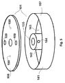
figure 5 présente un mode de réalisation d'une enveloppe rigide d'une galette selon l'invention, - la
figure 6 montre un exemple d'agencement des éléments internes d'une galette selon un autre mode de réalisation particulier de l'invention, - La
figure 7 montre un schéma simplifié d'un générateur de tension comportant un empilement de 20étages 200 selon lafigure 6 de l'invention.
Chacun de ces étages comporte une enveloppe rigide électriquement isolante 101 de forme cylindrique et aplatie et comportant un canal axial 135. Cette enveloppe renferme un certain nombre d'éléments enrobés dans du
Le premier étage 1001 est composée de l'enveloppe 101 comportant un premier et un second borniers de connexion 113
Le
Le
- the
figure 1 is a circuit diagram of a MARX generator; - the
figure 2 is a circuit diagram of a part of a Marx generator; - the
figure 3 is a circuit diagram of a portion of a Marx generator type 18L comprising slabs according to the invention; - the
figure 4 shows an example of arrangement of the elements of a wafer according to a particular embodiment of the invention; - the
figure 5 presents an embodiment of a rigid envelope of a wafer according to the invention, - the
figure 6 shows an example of arrangement of the internal elements of a wafer according to another particular embodiment of the invention, - The
figure 7 shows a simplified diagram of a voltage generator comprising a stack of 20stages 200 according to thefigure 6 of the invention.
Each of these stages comprises a rigid electrically
The first stage 100 1 is composed of the
The first
The second
The third
Ainsi, ce générateur comporte deux condensateurs par galette connectés électriquement en parallèle, les inductances de charge étant connectées en série de telle sorte que la tension d'entrée charge en parallèle les condensateurs et que ceux-ci se déchargent en série via les éclateurs.Thus, this generator comprises two capacitors per wafer electrically connected in parallel, the charge inductances being connected in series so that the input voltage loads in parallel the capacitors and they are discharged in series via the gaps.
La
Lesdits éléments sont constitués par une structure rigide annulaire supérieure 103, une structure rigide annulaire inférieure 104 et, insérés entre ces deux structures :
- une première et une seconde entretoise 132, 133
- un premier et un
second condensateurs - une première et une seconde
inductance de charge - une première partie des dits premier, second, troisième et quatrième borniers 113, 115, 114
et 116, ces borniers étant emmanchés dans des ouvertures pratiquées dans lesdites structures et comportant une seconde partie, de diamètre supérieur à celui de la première partie et disposée au dessus de lastructure annulaire supérieure 103 pour les premier etsecond borniers - un premier et un second taquet de connexion 134, 136.
En outre, les borniers de connexion et les taquets sont disposés selon le même plan.
On trouve ainsi, dans le sens horaire, la succession d'éléments suivants :
- Le premier condensateur 118, la première entretoise 132, les premier et troisième borniers 113, 114 et le
premier taquet 134, la première inductance decharge 111, lesecond condensateur 119, la seconde entretoise 133, les deuxième et quatrième borniers 115, 116 et lesecond taquet 136, la secondinductance de charge 112.
La structure supérieure est composée d'un premier demi-anneau conducteur 128 et d'un second demi anneau non conducteur 129 solidarisés entre eux à leurs extrémités par des vis 137. De même, la structure inférieure est composée d'un troisième demi-anneau conducteur 130 et d'un quatrième demi anneau non conducteur 131 solidarisés entre eux à leurs extrémités par des vis 137. De plus, le premier
La première inductance de
La seconde
Afin d'éviter des renforcements de champ à l'origine de claquages électriques, toutes les arêtes des borniers de connexion, des demi-éclateurs, des inductances, des entretoises, ainsi que des condensateurs sont arrondies.
Comme montré sur la
- une première partie creuse 107 en forme de moule à savarin à fond plat avec une première portion tubulaire extérieure 141 et une seconde portion tubulaire intérieure 142
formant le canal 135, ces portions tubulaires étant coaxiales solidarisées par une plaque annulaire 143 à leurs base - une seconde partie 108 en forme de plaque annulaire destinée à être placée au dessus de la cavité de la première partie et fixée par vis audit premier semi-anneau conducteur 128 via les alésages taraudés 106, 150 et de sorte à former l'enveloppe.
- La première partie creuse 107 de l'enveloppe est aussi fixée par des vis au dit troisième semi-anneau conducteur 130 via des alésages taraudés 106 pratiqués dans ce dernier.
Contrairement aux étages selon l'état de la technique, ce nouveau type d'étage permet l'utilisation de condensateurs pré-enrobés disponibles dans le commerce. Les impédances de charge des condensateurs intégrés à l'étage peuvent être des résistances carbone disponibles dans le commerce, ou bien des inductances spécialement conçues. Ces dernières permettent de faire fonctionner le générateur en régime répétitif.
Le procédé de fabrication d'un étage selon les figures précédentes peut être le suivant.
- Le premier demi-anneau conducteur 128 et le second demi-anneau non conducteur 129 sont solidarisés à l'un des premier et
second condensateurs premier taquet 134 sont fixés à lastructure annulaire supérieure 103. - Le troisième demi-anneau conducteur 130 et le quatrième demi-anneau non conducteur 131 sont ensuite solidarisés sur les faces libres des premier et
second condensateurs inductance 111 sont ensuite connectées aux premier et troisième borniers 113, 114 tandis que celles de la deuxièmeinductance 112 sont connectées aux second et au quatrième borniers 115, 116. - L'ensemble ainsi réalisé est placé dans la partie creuse de l'enveloppe de sorte que les connexions des taquets destinées chacune à recevoir un demi-éclateur se trouvent en regard des ouvertures 144 de ladite seconde portion tubulaire intérieure 142 de l'enveloppe.
- Les premier et second demi-éclateurs sont ensuite connectés respectivement aux premier et second taquets.
- La partie creuse 107 de l'enveloppe est ensuite remplie de gel silicone de façon à enrober ledit ensemble. Une fois que la partie creuse 107 est remplie, un couvercle isolant à savoir la seconde partie 108 en forme de plaque annulaire est fixée par vis au premier demi-anneau conducteur 128 permettant ainsi d'assurer une protection mécanique à l'ensemble. Seuls les quatre borniers de connexion et les deux supports pour les éclateurs restent accessibles.
- L'empilement d'étages selon l'invention pour former par exemple un générateur de Marx est ensuite réalisé suivant l'état de la technique connu.
- a first and a
second spacer - first and
second capacitors - first and
second load inductors - a first part of said first, second, third and
fourth terminals annular structure 103 for the first and second terminal blocks 113, 115 and below the lowerannular structure 104 for the third and fourth terminal blocks 114, 116, - first and
second connection tabs
In addition, the connection terminal blocks and the cleats are arranged in the same plane.
We thus find, in the clockwise direction, the succession of following elements:
- The
first capacitor 118, thefirst spacer 132, the first and third terminal blocks 113, 114 and thefirst cleat 134, thefirst load inductor 111, thesecond capacitor 119, thesecond spacer 133, the second and fourth terminal blocks 115, 116 and thesecond cleat 136, thesecond load inductor 112.
The upper structure is composed of a first conductive half-
The
The
In order to avoid field reinforcements causing electrical breakdowns, all the edges of the connection terminals, half-spark gaps, inductances, spacers, as well as capacitors are rounded.
As shown on the
- a first
hollow portion 107 in the form of a flat bottom savarin mold with a first outertubular portion 141 and a second innertubular portion 142 forming thechannel 135, these tubular portions being coaxial secured by anannular plate 143 at their base - a
second portion 108 in the form of an annular plate intended to be placed above the cavity of the first part and screwed to saidfirst semiconductor ring 128 via the threaded bores 106, 150 and so as to form the envelope.
- The first
hollow part 107 of the casing is also fixed by screws to said thirdconductive semi-ring 130 via threadedbores 106 made in the latter.
Unlike state-of-the-art floors, this new type of floor allows the use of commercially available pre-coated capacitors. The load impedances of the capacitors integrated in the stage may be commercially available carbon resistors, or specially designed inductors. These last allow to operate the generator in repetitive mode.
The method of manufacturing a stage according to the preceding figures may be the following.
- The first conductive half-
ring 128 and the second non-conductive half-ring 129 are secured to one of the first andsecond capacitors screws 137 and then the inductors, the spacers and the first and second terminal blocks. and thefirst cleat 134 are attached to the upperannular structure 103. - The third conductive half-
ring 130 and the fourth non-conductive half-ring 131 are then secured to the free faces of the first andsecond capacitors spacers inductors fourth terminals 114 116 and thesecond stop 136 are fixed thereto. The wire ends of thefirst inductor 111 are then connected to the first and third terminal blocks 113, 114 while those of thesecond inductor 112 are connected to the second and fourth terminal blocks 115, 116. - The assembly thus produced is placed in the hollow part of the envelope so that the connections of the cleats, each intended to receive a half-spark gap, are opposite the
openings 144 of said second innertubular portion 142 of the envelope. - The first and second half-gaps are then respectively connected to the first and second tabs.
- The
hollow portion 107 of the envelope is then filled with silicone gel so as to coat said assembly. Once thehollow part 107 is filled, an insulating cover, namely thesecond part 108 in the form of an annular plate, is screwed to the first conductive half-ring 128 thus making it possible to provide mechanical protection to the assembly. Only the four connection terminals and the two supports for the spark gaps remain accessible. - The stack of stages according to the invention to form, for example, a Marx generator is then produced according to the state of the prior art.
Pour le fonctionnement, un circuit d'alimentation en courant charge, en parallèle, les condensateurs via les borniers de connexion, les inductances ou résistances de charges, et les premier et troisième demi-anneaux conducteurs, tandis qu'une fois chargés à la tension disruptive des éclateurs, les condensateurs se déchargent en série via les premier et troisième demi-anneaux conducteurs, les taquets et les demi-éclateurs.For operation, a current supply circuit charges, in parallel, the capacitors via the connection terminals, the inductances or load resistances, and the first and third conductive half-rings, whereas once charged to the voltage Disruptive spark gaps, the capacitors are discharged in series via the first and third half-rings drivers, cleats and half-sparkers.
Ce type d'étage permet de construire des générateurs de MARX compacts qui peuvent être utilisés dans différents domaines tels que l'émission d'ondes électromagnétiques, la radiographie-éclair, tests de compatibilités électromagnétiques, applications médicales et toutes autres applications nécessitant l'utilisation de tels générateursThis type of stage makes it possible to build compact MARX generators that can be used in various fields such as electromagnetic wave emission, flash radiography, electromagnetic compatibility tests, medical applications and any other applications requiring the use such generators
la
Lesdits éléments internes sont constitués par une structure rigide annulaire supérieure 201, une structure rigide annulaire inférieure 202 et, fixés entre ces deux structures :
huit condensateurs et 234- une première et une seconde résistance de charge,
- une première partie de premier, second, troisième et quatrième borniers 217, 218,219, 220, ces borniers étant emmanchés dans des ouvertures pratiquées dans lesdites structures et comportant une seconde partie, de diamètre supérieur à celui de la première partie et disposée au dessus de la
structure annulaire supérieure 201 pour les premier etsecond borniers 217, 218 et au dessous de la structure annulaire inférieure 202 pour les troisième et quatrième borniers de connexion 114, 116, - un premier et un second taquet de connexion 220, 221.
En outre, les borniers de connexion et les taquets sont disposés selon le même plan. On trouve ainsi, dans le sens horaire, la succession d'éléments suivants :
- Les condensateurs et les résistances de charge sont fixées auxdites structures annulaires inférieure et supérieure par des inserts, tels de vis.
La première résistance de charge, non visible sur le dessin car cachée par le second arc d'anneau non conducteur 204, relie le bornier 217 solidaire du second arc d'anneau non conducteur 204 au troisième
Le premier bornier 217 est connecté électriquement à une première borne des condensateurs par le premier arc d'anneau conducteur 203 et le quatrième bornier est connecté électriquement à une seconde borne des condensateurs par le troisième
Afin d'éviter des renforcements de champ à l'origine de claquages électriques, toutes les arêtes des pièces du montage sont arrondies, notamment celles en matériau conducteur. L'épaisseur des arcs d'anneau conducteurs est préférablement comprise entre 2 et 6 mm : elle doit être la plus faible possible afin d'optimiser la densité d'énergie du générateur.
Lorsqu'il y a suffisamment de condensateurs, comme par exemple dans le cas de la
La
Par rapport à un générateur à simple enveloppe, un tel générateur avec une première enveloppe externe 311 électriquement conductrice et une seconde enveloppe interne 312 en matériau non électriquement conducteur possède un rendement plus élevé. En effet, cette double enveloppe permet de former une capacité supplémentaire de sorte que lors du déclenchement des éclateurs, cette capacité supplémentaire assure le maintien de la tension nominale au sein des étages et évite ainsi une chute de tension.Said internal elements consist of an upper rigid
- eight
capacitors - a first and a second load resistor,
- a first portion of first, second, third and
fourth terminals annular structure 202 for the third and fourth terminal blocks 114, 116, - first and second connection tabs 220, 221.
In addition, the connection terminal blocks and the cleats are arranged in the same plane. We thus find, in the clockwise direction, the succession of following elements:
- Capacitors and load resistors are attached to said lower and upper annular structures by inserts, such as screws.
The first load resistor, which is not visible on the drawing because it is hidden by the second
The first terminal block 217 is electrically connected to a first terminal of the capacitors by the first
In order to avoid field reinforcements at the origin of electrical breakdowns, all the edges of the parts of the assembly are rounded, in particular those made of conductive material. The thickness of the conductive ring arcs is preferably between 2 and 6 mm: it must be as small as possible in order to optimize the energy density of the generator.
When there are enough capacitors, as for example in the case of
The
This
With respect to a single envelope generator, such a generator with a first electrically conductive
Bien entendu, de nombreuses modifications peuvent être apportées aux modes de réalisation précédemment décrits sans sortir du cadre de l'invention. Ainsi, les étages peuvent comporter un nombre différent de condensateurs, ces derniers étant alors répartis de façon différente entre les structures annulaires inférieure et supérieure.Of course, many modifications can be made to the previously described embodiments without departing from the scope of the invention. Thus, the stages may comprise a different number of capacitors, the latter then being distributed differently between the lower and upper annular structures.
Ce type de générateur est à même de fournir· la quantité d'énergie nécessaire à l'émission de rayons-X.This type of generator is able to provide the amount of energy needed to emit X-rays.
Par ailleurs, une résine pourrait être utilisée à la place du gel silicone, voire un autre gel diélectrique.In addition, a resin could be used in place of the silicone gel, or even another dielectric gel.
De plus, les demi-éclateurs peuvent être connectés aux condensateurs sans les taquets de connexion par exemple en étant connectés directement aux demi-anneaux conducteurs correspondants par une connexion filaire.In addition, the half-gaps can be connected to the capacitors without the connection tabs, for example by being connected directly to the corresponding half-rings by a wire connection.
Par ailleurs, l'angle des arcs d'anneau conducteurs des structures annulaires inférieure et supérieure est préférablement compris entre 150 et 330 degrés.On the other hand, the angle of the conductive ring arcs of the lower and upper annular structures is preferably between 150 and 330 degrees.
Claims (13)
Applications Claiming Priority (1)
| Application Number | Priority Date | Filing Date | Title |
|---|---|---|---|
| FR1201183A FR2989851A1 (en) | 2012-04-20 | 2012-04-20 | GALETTE FOR VOLTAGE GENERATOR AND VOLTAGE GENERATOR |
Publications (2)
| Publication Number | Publication Date |
|---|---|
| EP2660977A1 true EP2660977A1 (en) | 2013-11-06 |
| EP2660977B1 EP2660977B1 (en) | 2015-04-29 |
Family
ID=48141728
Family Applications (1)
| Application Number | Title | Priority Date | Filing Date |
|---|---|---|---|
| EP20130002072 Not-in-force EP2660977B1 (en) | 2012-04-20 | 2013-04-19 | Stage for voltage generator and related voltage generator |
Country Status (2)
| Country | Link |
|---|---|
| EP (1) | EP2660977B1 (en) |
| FR (1) | FR2989851A1 (en) |
Families Citing this family (1)
| Publication number | Priority date | Publication date | Assignee | Title |
|---|---|---|---|---|
| CN108365834B (en) * | 2018-02-05 | 2021-05-14 | 中国工程物理研究院应用电子学研究所 | Lightweight miniaturized pulse power device |
Citations (5)
| Publication number | Priority date | Publication date | Assignee | Title |
|---|---|---|---|---|
| GB401737A (en) * | 1932-05-20 | 1933-11-20 | Thomas Edward Allibone | Improvements in apparatus for the generation of electric high voltage impulses |
| GB509614A (en) * | 1937-01-21 | 1939-07-19 | British Thomson Houston Co Ltd | Improvements in and relating to means for the generation of impulse voltages |
| US2417452A (en) * | 1944-01-17 | 1947-03-18 | Raytheon Mfg Co | Electrical system |
| EP0162766A1 (en) * | 1984-05-02 | 1985-11-27 | Societe De Verrerie Et De Thermometrie | High-energy and high-voltage storage device, and its use as a pulse generator |
| FR2823033A1 (en) | 2001-03-28 | 2002-10-04 | I S L Inst Franco Allemand De | Generator of high voltage pulses of MARX type, comprising capacitors fitted concentrically in two rings and a discharge gap with resistances in each tier |
-
2012
- 2012-04-20 FR FR1201183A patent/FR2989851A1/en not_active Withdrawn
-
2013
- 2013-04-19 EP EP20130002072 patent/EP2660977B1/en not_active Not-in-force
Patent Citations (5)
| Publication number | Priority date | Publication date | Assignee | Title |
|---|---|---|---|---|
| GB401737A (en) * | 1932-05-20 | 1933-11-20 | Thomas Edward Allibone | Improvements in apparatus for the generation of electric high voltage impulses |
| GB509614A (en) * | 1937-01-21 | 1939-07-19 | British Thomson Houston Co Ltd | Improvements in and relating to means for the generation of impulse voltages |
| US2417452A (en) * | 1944-01-17 | 1947-03-18 | Raytheon Mfg Co | Electrical system |
| EP0162766A1 (en) * | 1984-05-02 | 1985-11-27 | Societe De Verrerie Et De Thermometrie | High-energy and high-voltage storage device, and its use as a pulse generator |
| FR2823033A1 (en) | 2001-03-28 | 2002-10-04 | I S L Inst Franco Allemand De | Generator of high voltage pulses of MARX type, comprising capacitors fitted concentrically in two rings and a discharge gap with resistances in each tier |
Also Published As
| Publication number | Publication date |
|---|---|
| EP2660977B1 (en) | 2015-04-29 |
| FR2989851A1 (en) | 2013-10-25 |
Similar Documents
| Publication | Publication Date | Title |
|---|---|---|
| EP0068927B1 (en) | Capacitor arrangement for forming an integrated voltage multiplier | |
| EP2250655B1 (en) | Multiple-coil supercapacitor | |
| EP0162766B1 (en) | High-energy and high-voltage storage device, and its use as a pulse generator | |
| EP2115815A1 (en) | Process for manufacturing a cable for connecting the poles of a battery, an installation for implementing said process, and the cable obtained | |
| FR2569319A1 (en) | PULSE GENERATOR | |
| EP1705772A2 (en) | Synthetic cable end for D. C. cable | |
| EP2660977B1 (en) | Stage for voltage generator and related voltage generator | |
| EP0673068A1 (en) | Overvoltage protection device in integrated circuits | |
| FR2508718A1 (en) | CONNECTION ASSEMBLY OF TWO MULTI-LAYERED CABLES ESPECIALLY IN THE STATORIC WINDING OF A HIGH VOLTAGE ALTERNATOR | |
| EP0430755B1 (en) | High voltage unit for X-ray tube with a secondary circuit integrated cooling tank | |
| FR2520927A1 (en) | VACUUM CHAMBER FOR ARC EXTINGUISHING | |
| EP3272010B1 (en) | High-voltage pulse generator | |
| FR2899426A1 (en) | Low power x-ray generator for realizing non-invasive examination of object, has voltage multipliers arranged in shadow zones created by anode and cathode of bipolar x-ray tube and located behind respective inputs of cathode and anode | |
| FR2650935A1 (en) | ELECTROSTATIC ELECTRONIC ACCELERATOR | |
| EP1760884B1 (en) | High-voltage pulse generator | |
| FR3020397A1 (en) | SEISMIC WAVE GENERATION PROBE | |
| EP2896127B1 (en) | Generator for rectangular highpower pulses with adjustable slope | |
| WO1989008950A1 (en) | Saturable inductance electric pulse generator | |
| CH669277A5 (en) | High tension electric cable with extruded insulating layers - consists of synthetic materials of different dielectric properties sandwiched between 2 semiconducting layers | |
| EP1760883B1 (en) | Element of an energie accumulating device and associated generator | |
| FR2726118A1 (en) | SURGE PROTECTION DEVICE | |
| EP2541712B1 (en) | Electrical line with cross-bonding cable junctions | |
| EP0724332B1 (en) | Switching device for a high voltage circuit with pulse transformers | |
| WO2018154242A2 (en) | Electronic component having a transistor and interdigitated fingers to form at least a portion of a capacitive component within the electronic component | |
| CA3029365A1 (en) | Power amplification device |
Legal Events
| Date | Code | Title | Description |
|---|---|---|---|
| PUAI | Public reference made under article 153(3) epc to a published international application that has entered the european phase |
Free format text: ORIGINAL CODE: 0009012 |
|
| 17P | Request for examination filed |
Effective date: 20130515 |
|
| AK | Designated contracting states |
Kind code of ref document: A1 Designated state(s): AL AT BE BG CH CY CZ DE DK EE ES FI FR GB GR HR HU IE IS IT LI LT LU LV MC MK MT NL NO PL PT RO RS SE SI SK SM TR |
|
| AX | Request for extension of the european patent |
Extension state: BA ME |
|
| GRAP | Despatch of communication of intention to grant a patent |
Free format text: ORIGINAL CODE: EPIDOSNIGR1 |
|
| INTG | Intention to grant announced |
Effective date: 20141117 |
|
| RIN1 | Information on inventor provided before grant (corrected) |
Inventor name: DUPEROUX, JEAN-PIERRE Inventor name: SCHURRER, ANDRE Inventor name: PINGUET, SYLVAIN |
|
| GRAS | Grant fee paid |
Free format text: ORIGINAL CODE: EPIDOSNIGR3 |
|
| GRAA | (expected) grant |
Free format text: ORIGINAL CODE: 0009210 |
|
| RBV | Designated contracting states (corrected) |
Designated state(s): CH DE FR LI |
|
| AK | Designated contracting states |
Kind code of ref document: B1 Designated state(s): CH DE FR LI |
|
| REG | Reference to a national code |
Ref country code: CH Ref legal event code: EP |
|
| REG | Reference to a national code |
Ref country code: DE Ref legal event code: R096 Ref document number: 602013001580 Country of ref document: DE Effective date: 20150611 |
|
| REG | Reference to a national code |
Ref country code: DE Ref legal event code: R097 Ref document number: 602013001580 Country of ref document: DE |
|
| PLBE | No opposition filed within time limit |
Free format text: ORIGINAL CODE: 0009261 |
|
| STAA | Information on the status of an ep patent application or granted ep patent |
Free format text: STATUS: NO OPPOSITION FILED WITHIN TIME LIMIT |
|
| REG | Reference to a national code |
Ref country code: FR Ref legal event code: PLFP Year of fee payment: 4 |
|
| 26N | No opposition filed |
Effective date: 20160201 |
|
| PGFP | Annual fee paid to national office [announced via postgrant information from national office to epo] |
Ref country code: FR Payment date: 20160307 Year of fee payment: 4 |
|
| PGFP | Annual fee paid to national office [announced via postgrant information from national office to epo] |
Ref country code: DE Payment date: 20160307 Year of fee payment: 4 |
|
| REG | Reference to a national code |
Ref country code: CH Ref legal event code: PL |
|
| PG25 | Lapsed in a contracting state [announced via postgrant information from national office to epo] |
Ref country code: LI Free format text: LAPSE BECAUSE OF NON-PAYMENT OF DUE FEES Effective date: 20160430 Ref country code: CH Free format text: LAPSE BECAUSE OF NON-PAYMENT OF DUE FEES Effective date: 20160430 |
|
| REG | Reference to a national code |
Ref country code: DE Ref legal event code: R119 Ref document number: 602013001580 Country of ref document: DE |
|
| REG | Reference to a national code |
Ref country code: FR Ref legal event code: ST Effective date: 20171229 |
|
| PG25 | Lapsed in a contracting state [announced via postgrant information from national office to epo] |
Ref country code: DE Free format text: LAPSE BECAUSE OF NON-PAYMENT OF DUE FEES Effective date: 20171103 Ref country code: FR Free format text: LAPSE BECAUSE OF NON-PAYMENT OF DUE FEES Effective date: 20170502 |