US4672532A - Software/hardware integration control system - Google Patents
Software/hardware integration control system Download PDFInfo
- Publication number
- US4672532A US4672532A US06/817,770 US81777086A US4672532A US 4672532 A US4672532 A US 4672532A US 81777086 A US81777086 A US 81777086A US 4672532 A US4672532 A US 4672532A
- Authority
- US
- United States
- Prior art keywords
- file
- interrupt
- software
- ics
- configuration object
- Prior art date
- Legal status (The legal status is an assumption and is not a legal conclusion. Google has not performed a legal analysis and makes no representation as to the accuracy of the status listed.)
- Expired - Fee Related
Links
Images

Classifications
-
- G—PHYSICS
- G06—COMPUTING; CALCULATING OR COUNTING
- G06F—ELECTRIC DIGITAL DATA PROCESSING
- G06F9/00—Arrangements for program control, e.g. control units
- G06F9/06—Arrangements for program control, e.g. control units using stored programs, i.e. using an internal store of processing equipment to receive or retain programs
- G06F9/44—Arrangements for executing specific programs
- G06F9/445—Program loading or initiating
- G06F9/44521—Dynamic linking or loading; Link editing at or after load time, e.g. Java class loading
-
- Y—GENERAL TAGGING OF NEW TECHNOLOGICAL DEVELOPMENTS; GENERAL TAGGING OF CROSS-SECTIONAL TECHNOLOGIES SPANNING OVER SEVERAL SECTIONS OF THE IPC; TECHNICAL SUBJECTS COVERED BY FORMER USPC CROSS-REFERENCE ART COLLECTIONS [XRACs] AND DIGESTS
- Y10—TECHNICAL SUBJECTS COVERED BY FORMER USPC
- Y10S—TECHNICAL SUBJECTS COVERED BY FORMER USPC CROSS-REFERENCE ART COLLECTIONS [XRACs] AND DIGESTS
- Y10S707/00—Data processing: database and file management or data structures
- Y10S707/99941—Database schema or data structure
- Y10S707/99944—Object-oriented database structure
- Y10S707/99945—Object-oriented database structure processing
-
- Y—GENERAL TAGGING OF NEW TECHNOLOGICAL DEVELOPMENTS; GENERAL TAGGING OF CROSS-SECTIONAL TECHNOLOGIES SPANNING OVER SEVERAL SECTIONS OF THE IPC; TECHNICAL SUBJECTS COVERED BY FORMER USPC CROSS-REFERENCE ART COLLECTIONS [XRACs] AND DIGESTS
- Y10—TECHNICAL SUBJECTS COVERED BY FORMER USPC
- Y10S—TECHNICAL SUBJECTS COVERED BY FORMER USPC CROSS-REFERENCE ART COLLECTIONS [XRACs] AND DIGESTS
- Y10S707/00—Data processing: database and file management or data structures
- Y10S707/99941—Database schema or data structure
- Y10S707/99948—Application of database or data structure, e.g. distributed, multimedia, or image
Definitions
- This invention relates to the interfacing of software to hardware, more specifically to a system for translating hardware/software interface specifications simultaneously into specific microprocessor executable code and commands for the linker/loading system of a selected hardware configuration.
- Computer based instruments are in fact systems of mechanical and electronic components interacting with the computer program stored in those hardware components.
- the task of correctly interfacing hardware and software has always been a rather intricate one and very time consuming.
- the system of the present invention allows the instrument designer to specify the hardware/software interface in a high order language in an interactive way. That system then translates those specifications into code executable by the instrument computer as well as other commands to be executed by the program linking/loading systems. It thus reduces to minutes a development process that might otherwise take up to several days or even weeks.
- Pascal When a high order language, such as Pascal is used the program is machine independent by virtue of the nature of the language. Pascal source programs do not vary, regardless of the process or host computer on which it is to be used. However, with conventional Pascal, there's no direct way to specify implementation-dependent requirements such as interrupt vectors, restart routines, or memory configuration.
- the disclosed integration control system relieves the computer based instrument designer from having to design and debug hundreds to thousands of lines of computer level code as well as having to familiarize himself with increasingly complex linker/loading systems requiring dozens of specific commands in a special linker command language.
- the present invention provides a method and a system for integrating a high level language program together with the hardware limitations of a selected prototype processor. This is accomplished automatically by interacting with the designer to prepare a source file which includes software, hardware and interrupt configuration specifications for a selected prototype processor. It also includes processing of the source file generated above to generate a linker command file and a configuration object file.
- the linker command file controls the linking process of the high level language program with the configuration object file to generate a load module executable by the prototype processor. During linking selected routines from the run-time library for the particular high level language may also be included as necessary.
- the interaction with the designer includes the prompting of the designer for necessary inputs as to software and prototype processor hardware and interrupt specifications, then, in response to those inputs a source file is created.
- the configuration object file referred to above includes interrupt vectors, interrupt service routines, a reset routine and a program initialization routine for the prototype processor.
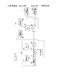
- FIG. 1 shows a flow diagram of the integration control system present invention.
- FIG. 2 is a simplified block diagram of a terminal interconnected with a host computer representing the embodiment of the present invention.
- Block 2 represents the designer's interactive specifications of the hardware, software and interrupt configurations of the prototype in response to prompts from the prompter of block 4. Those specifications are then utilized by prompter 4 to generate the integration source file of block 6.
- the source file of block 6 is processed by the processor (block 8) producing the linker command file (block 12) and the configuration object file (block 10).
- the Pascal object file (block 14), the software to be run on the prototype processor system, together with the Pascal run-time support library (block 16), the configuration object file (block 10), and the linker command file (block 12) are applied to linker 18.
- the configuration object file is linked to the Pascal object files and the run-time support library.
- linker 18 Under the control of the linker command file, linker 18 will produce a load file (block 20) which can be executed by the prototype processor system specified in response to prompter 4.
- the configuration object file (block 10) includes interrupt vectors, interrupt service routines, a reset routine and program initialization routine for the prototype processor system specified.
- the linker command file (block 12) generated for the particular prototype processor system ties together the Pascal object code (block 14), the configuration object file (block 10), and the appropriate run-time support libraries.
- the linker command file (block 12) also arranges the object code in accordance with the prototype processor system's memory layout as specified in response to prompter 4.
- ICS In order for the ICS to function it is necessary that the basics of various prototype processor systems be included as working parameters. These parameters include information such as maximum memory size and configurations, interrupt procedures, etc. For purposes of the following discussion examples will be included of an ICS system which can interface a Pascal language program with any of the following microprocessors: 8086, 8086/8087, 8088, and 8088/8087.
- ICS integration source file (block 6) provides a concise, human-readable description of the hardware/software interface, and can be used as a design document.
- the software will be developed in parallel with the hardware, and that parts of the program will be tested before the entire program is developed.
- the default ICS configuration object file and linker command file can be used.
- the ICS integration source file (block 6) will be created and modified to match the program's changing environment.
- prompter 4 queries the user for information as to the prototype processor system configuration.
- Table 1 shows a typical set of prompts, user responses, and a comment field forming a typical integration source file (block 6).
- the ICS prompter (block 4) is an interactive program that creates the ICS integration source file. Prompter 4 asks questions about the prototype processor system, object files and interrupt configuration, and builds the file according to the responses.
- prompter 4 When ICS is invoked prompter 4 introduces itself and displays a menu of options to choose from. In the "question mode", prompter 4 begins asking questions and building the integration source file. Immediately after ICS is invoked, prompter 4 first creates a default integration source file as shown in Table 3 and then modifies it according to the designer's specifications.
- the integration source file is applied to processor 8 to generate the linker command file (block 12) and the configuration object file (block 10).
- Table 2 is a typical linker command file which would be generated from the integration source file of Table 1.
- ICS processor 8 When ICS processor 8 finishes reading the integration source file (block 6), it invokes the assembler of the host computer to create the configuration (block 10) and listing from the integration source file (block 6) is automatically deleted after the assembler finishes.
- ICS processor 8 finds any errors in the ICS integration source file, it does not produce the linker command file or configuration object file, and the listing shows only the ICS directives and the associated error messages.
- the ICS configuration object code (block 10) performs the following tasks:
- ICS produces two types of code to carry out these tasks:
- Interrupt handling code--Interrupt vectors and the register save/restore routines that may be used in interrupt handling.
- Initialization and reset code--Code that initializes the segment registers (CS, DS, SS, ES), the stack pointer, the heap pointers, the BP register, the 8087, and the floating point status word variable.
- This code may also include a routine called COPYVECTORS that copies the interrupt vectors from ROM to RAM, and also a RESET vector which creates the reset code (a JMPS instruction) at location FFFFO.
- ICS configuration object file may be used for interrupt handling.
- Each interrupt type may need to save and restore the registers of the 8086 and 8087.
- the actual code generated by ICS depends upon the ICS integration source file choices for each interrupt type.
- ICS.VROM interrupt vectors
- ICS.INSTR executable code
- Each interrupt service routine has a portion of code devoted to its handling.
- the assembly code for handling each interrupt type follows a general pattern.
- Uppercase words are either actual assembler directives or instructions.
- Lowercase words are a description of the function of the assembler code and represent one or more lines from the listing.
- ;VECTOR is the ICS directive that declares the interrupt service routine and the type(s) handled by that routine.
- INTSERVE represents the routine that services the interrupt type number "m”.
- VECTOR$ points to the beginning of the interrupt handling code for this interrupt type.
- the "save some registers and preserve traceback" code performs two functions: saves selected registers and allows the runtime error checking routines to trace the source of runtime errors.
- the "call interrupt service routine" code calls the routine that services the interrupt type.
- the "restore registers" code restores those registers that were saved. (Refer to Table 4 for a list of ICS subroutines that are used to save and restore registers.)
- the IRET instruction returns control to the interrupted routine.
- the RESUME ICS.VROM directive causes any lines of code that follow the directive to be placed in the ICS.VROM section.
- create interrupt vector in memory a vector is created in memory pointing to the beginning of the interrupt handling code. This is done with two assembler directives (an example is shown in the sample ICS listing). The first defines the location where the interrupt vector is to be placed. The second creates the value of the interrupt vector in that location.
- sample ICS listing shows the particular code produced for each of the interrupt types in a sample ICS source file.
- Table 4 lists the subroutines that may be included in the ICS object code.
- Interrupt types specified with the INTERRUPTS -- TYPES -- USED directive, but not mentioned in a VECTOR directive, are referred to as undefined interrupt types.
- the FAULT -- NOTIFICATION directive is used to specify the interrupt handling routine for these undefined types.
- the RESTART -- LABEL directive generates interrupt vectors for these undefined interrupts. See the sample ICS listing, shown later in this section, for an example.
- the interrupt vectors must be created (in CONSTANTS -- ROM) and then transferred to the interrupt vector area (ICS.VRAM) at runtime.
- the FAULT -- NOTIFICATION directive reserves the appropriate areas in ICS.VRAM for the interrupt vectors and sets up the code to transfer the vectors there during program initialization.
- the table created in ICS.VROM has the form shown in Table 5.
- the program initialization code is created by the RESTART -- LABEL directive starting at the location PASCAL -- BEGIN.
- the initialization code is executed at runtime and performs the following tasks:
- the reset code is a JMPS instruction, placed at location FFFFOH, pointing to the intialization code. After the microprocessor is reset, this JMPS instruction causes the initialization code to be executed.
- the RESTART -- LABEL directive also includes the code for any interrupt-related subroutines that are needed (as listed in Table 4.)
- ICS When ICS is invoked, if the -l (listing) or -o (object code) option if specified, and the ICS integration source file contains no errors, ICS generates a temporary assembly language source file from the ICS directives. If the o-option is included, ICS invokes the 8086 assembler to create the object file (filename.io) and assembler listing (filename.il). The assembler invocation that ICS uses looks something like this:
- the input to the assembler consists of two files, which are processed as if they were concatenated into a single file.
- the first file, /lib/8086/ics.mc consists mostly of assembler macro definitions that are used by the second file.
- the second file is the temporary assembly language source file that ICS has just created. After the assembler finishes, the temporary file is automatically deleted.
- the temporary assembly language source file is saved as the listing file (filename.il). If the designer would like to modify the code that ICS produces, he can edit this source file or create a modified version of the ICS macro file. However, modifying the code that ICS produces may cause your program to be linked, loaded, or executed incorrectly.
- This assembly command line effectively concatenates his macro definitions (mymacros) with the ICS produced myprog.il and then assembles this file.
- Table 6 lists the assembly language macros in the ics.ms file and their functions.
- the ICS listing file produced by ICS from a hypothetical ICS integration source file is now shown.
- the ICS configuration object code that is linked into the executable load module that runs on the prototype processor system can be understood.
- ICS creates a temporary file from the ICS integration source file. This file is assembled and produces the ICS configuration object file and an assembly listing called the ICS listing file.
- Table 7 is an actual listing produced by ICS.
- the assembler uses macro definitions from the file /lib/8086/ics.mc.
- the macro definitions and their line numbers from the ics.mc file are not shown in the listing.
- Lines 1-187 are from ics.mc; the remaining lines in the listing are the ICS directives and the assembly language statements they create. (Lines 11-186 are the macro definitions from ics.mc, which are not listed.)
- Lines 4-9 set up section ICS.INSTR and the standard global symbols, and associate the value DATABASEQQ with the DS register.
- Line 202 sets up section ICS.VROM, which will contain the interrupt vectors.
- Lines 211-235 save the 8086 registers in-line, call the interrupt service routine (called NMI), restore the registers, and return from the interrupt.
- NMI interrupt service routine
- Lines 236-238 create an interrupt vector at address 0008 that points to the beginning of the register save code (line 212). This spot was marked by the "VECTOR$ SET $" directive on line 210.
- Lines 237 and 238 are typical of lines that create an interrupt vector.
- ORG defines the location of the vector. This code is placed in the interrupt vector table at address 8H (for interrupt type 2).
- WORD creates the interrupt vector.
- the first word created is VECTOR$-CODEBASEQQ. This word is the offset from the CS register which points to the code that saves registers (starting at location 0, lines 212).
- the second word created, BITS(CODEBASEQQ,4,16) contains the top 16 bits of CODEBASEQQ (which has 20 bits). These 16 bits will be placed in the CS register when the interrupt occurs.
- the VECTOR directive on line 239 generates lines 240-249.
- This directive code is similar to the previous code (lines 211-235), except that the 8086 registers are not saved and restored in-line. Instead, they are saved and restored using the subroutines SAV.86$ and RES.86$, the code for which will be generated by the RESTART -- LABEL directive.
- VECTOR directive invocation on line 250 generates the lines 251-262. Since the SAVE-FLOATING -- POINT and EXCEPT 13 FOR directives direct ICS to save the floating point registers for interrupt types 32 and 34, lines 255-257 save the FPSWQQ variable and the 8087 status on the stack before the call to the interrupt service routine, and restore them afterward.
- VECTOR directive on line 263 generates lines 264-275. This directive is essentially the same as the previous directive.
- the VECTOR directive on line 276 generates lines 277-282. Because of the OWN -- CODE parameter, no register save and restore code is generated. The four interrupt vectors that are generated all vector directly to TIMER (lines 279-282).
- the FAULT -- NOTIFICATION directive (back at line 206) specified that undefined interrupts are to be handled by the interrupt service routine called BAD -- INTERRUPT. Since interrupt types 33 and 35 are undefined (not listed in any VECTOR directives), lines 284-291 generate the code necessary to save the 8086 registers, call BAD -- INTERRUPT, and restore the registers. Lines 292-296 generate interrupt vectors to this code for types 33 and 35.
- Lines 298-352 generate the code for the 8086 and 8087 register save and restore routines: SAV.86$, RES.86$, SAV.87$, and RES.87$.
- the program initialization code starts at label PASCAL -- BEGIN (line 356).
- Lines 357-361 initialize DS, SS, and SP.
- Lines 362-366 initialize the heap pointers.
- Lines 368-374 initialize the 8087.
- Lines 377-381 initialize ES and BP.
- Line 384 jumps to the main Pascal program.
- Lines 386-391 set up the RESET vector FFFFO.
- Table 8 shows the interrupt type, the name of the interrupt service routine for that type, the ICS code that saves and restores registers after an interrupt, and the line numbers of the code in the ICS listing.
- the linker is involved, specifying only the linker command file that ICS has created and the load file to be created.
- Table 9 is a sample listing of the prompter (block 4) routine and Table 10 is a sample listing of the processor (block 8) routine.
- Terminal 40 includes a CRT 42, keyboard 43, processor 41, memory 44 and timing and control 45.
- terminal 40 includes I/0 46 to enable two way communication between the terminal and host computer 30.
- Host computer 30 includes CPU 32 which operates under the control of timing and control 36.
- host computer 30 includes memory 34 and I/0 38. I/0 38 is the communications link between host computer 30 and the peripherals, i.e. terminal 40, printer/plotter 39 and PROM programmer 37.
- the prompter and processor routines are initially stored in memory 34.
- the prompter routine is called up by CPU 32 from memory 34.
- the individual prompts are then transmitted to the CRT of terminal 40 via I/Os 38 and 46.
- the designer enters his responses via keyboard 43 which are then transmitted back to CPU 32 where the prompter routine formulates the integration source file (FIG. 1, block 6).
- processor routine is called-up by CPU 32 to convert the integration source to the linker command file and the configuration object file as discussed above.
- the machine independent program to be conditioned for use on the prototype processor system is loaded into host computer 30, together with the standard run-time support library for the language in which that program is written. If host computer 30 includes a compiler for the language, the machine independent program can be entered in either source or object form. In the above example the language of the desired program was to be Pascal.
- the executable load module includes, in machine language, the information and locations in the ROMs of the prototype processor system for that system to operate as per the program included in the Pascal object file.
- the host computer 30 can list the executable load module, via printer/plotter 39, or program test PROMs, via PROM programmer 37.
Abstract
A method and control system for integrating machine independent software written in a high level language with the hardware and software characteristics of a selected processor system to generate an executable load module in the same high level language with selected machine codes merged therewith to be run on the selected processor system. The method and system includes the interactive preparation of a source file containing software, hardware and interrupt configuration specifications of the selected processor system in response to designer inputs. Also included is the processing of the source file to generate a linker command file and a configuration object file. Additionally, the machine independent software is linked with the configuration object file under control of the linker command file to generate the executable load module for the selected processor system.
Description
This is a continuation of application Ser. No. 387,729, filed June 14,1982 and now abandoned.
This invention relates to the interfacing of software to hardware, more specifically to a system for translating hardware/software interface specifications simultaneously into specific microprocessor executable code and commands for the linker/loading system of a selected hardware configuration.
Computer based instruments are in fact systems of mechanical and electronic components interacting with the computer program stored in those hardware components. The task of correctly interfacing hardware and software has always been a rather intricate one and very time consuming. The system of the present invention allows the instrument designer to specify the hardware/software interface in a high order language in an interactive way. That system then translates those specifications into code executable by the instrument computer as well as other commands to be executed by the program linking/loading systems. It thus reduces to minutes a development process that might otherwise take up to several days or even weeks.
When a high order language, such as Pascal is used the program is machine independent by virtue of the nature of the language. Pascal source programs do not vary, regardless of the process or host computer on which it is to be used. However, with conventional Pascal, there's no direct way to specify implementation-dependent requirements such as interrupt vectors, restart routines, or memory configuration.
You could develop a large assembly language routine (to connect your Pascal program with the prototype hardware) and a linker command file (to specify your memory configuration). To do this, you would need detailed knowledge of the assembler, the linker, and the Pascal interface requirements. The task is time-consuming, and with so many low-level details to keep track of, errors are inevitable. There are no known prior art systems for generating the linker commands and the configuration object files automatically.
It would be desirable to have a system which provides you with a list of the items you need to specify in order to configure a program to a prototype--everything from the name of your compiled object program to the address where the program begins execution. Then, based on your responses, generates the configuration object file and linker commands needed to configure your prototype.
If such a system used high-level language directives, you could describe your prototype more quickly and with fewer errors. And the system could also check the validity of your statements, thus saving you from errors that would not be caught until later. It is believed that the present invention embodies such a system.
In accordance with the illustrated embodiment, the disclosed integration control system (ICS) relieves the computer based instrument designer from having to design and debug hundreds to thousands of lines of computer level code as well as having to familiarize himself with increasingly complex linker/loading systems requiring dozens of specific commands in a special linker command language.
The present invention provides a method and a system for integrating a high level language program together with the hardware limitations of a selected prototype processor. This is accomplished automatically by interacting with the designer to prepare a source file which includes software, hardware and interrupt configuration specifications for a selected prototype processor. It also includes processing of the source file generated above to generate a linker command file and a configuration object file.
The linker command file controls the linking process of the high level language program with the configuration object file to generate a load module executable by the prototype processor. During linking selected routines from the run-time library for the particular high level language may also be included as necessary.
The interaction with the designer includes the prompting of the designer for necessary inputs as to software and prototype processor hardware and interrupt specifications, then, in response to those inputs a source file is created.
The configuration object file referred to above includes interrupt vectors, interrupt service routines, a reset routine and a program initialization routine for the prototype processor.
FIG. 1 shows a flow diagram of the integration control system present invention.
FIG. 2 is a simplified block diagram of a terminal interconnected with a host computer representing the embodiment of the present invention.
When a high order language, such as Pascal, is utilized to generate a machine independent program the code produced by the compiler cannot be executed directly. The proper codes in the run-time library must be linked with the compiled code. Depending on the hardware and the software needs of the prototype processor system, the prototype processor system must be initialized for the program. The linker must be told where to store the generated code in the memory of the prototype processor system.
The software/hardware integration control system of the present invention functions generally as shown in the flow chart of FIG. 1. Block 2 represents the designer's interactive specifications of the hardware, software and interrupt configurations of the prototype in response to prompts from the prompter of block 4. Those specifications are then utilized by prompter 4 to generate the integration source file of block 6. The source file of block 6 is processed by the processor (block 8) producing the linker command file (block 12) and the configuration object file (block 10).
The Pascal object file (block 14), the software to be run on the prototype processor system, together with the Pascal run-time support library (block 16), the configuration object file (block 10), and the linker command file (block 12) are applied to linker 18. In linker 18, the configuration object file is linked to the Pascal object files and the run-time support library. Under the control of the linker command file, linker 18 will produce a load file (block 20) which can be executed by the prototype processor system specified in response to prompter 4.
The configuration object file (block 10) includes interrupt vectors, interrupt service routines, a reset routine and program initialization routine for the prototype processor system specified. The linker command file (block 12) generated for the particular prototype processor system ties together the Pascal object code (block 14), the configuration object file (block 10), and the appropriate run-time support libraries. The linker command file (block 12) also arranges the object code in accordance with the prototype processor system's memory layout as specified in response to prompter 4.
In order for the ICS to function it is necessary that the basics of various prototype processor systems be included as working parameters. These parameters include information such as maximum memory size and configurations, interrupt procedures, etc. For purposes of the following discussion examples will be included of an ICS system which can interface a Pascal language program with any of the following microprocessors: 8086, 8086/8087, 8088, and 8088/8087.
Before the Pascal object code (block 14) produced by a compiler can be executed, it must be supplemented with configuration object code (block 10) produced by ICS. If the designer/programmer already knows the details of the prototype processor system he can create and process an ICS integration source file (block 6) even before he begins programming in Pascal. In fact, the ICS integration source file (block 6) provides a concise, human-readable description of the hardware/software interface, and can be used as a design document.
It is likely, however, that the software will be developed in parallel with the hardware, and that parts of the program will be tested before the entire program is developed. In testing parts of the program in emulation mode, the default ICS configuration object file and linker command file can be used. As interrupt processing routines are added to the program and it is moved to the prototype processor system, the ICS integration source file (block 6) will be created and modified to match the program's changing environment.
When the ICS system is initiated, prompter 4 queries the user for information as to the prototype processor system configuration. Table 1 shows a typical set of prompts, user responses, and a comment field forming a typical integration source file (block 6).
The ICS prompter (block 4) is an interactive program that creates the ICS integration source file. Prompter 4 asks questions about the prototype processor system, object files and interrupt configuration, and builds the file according to the responses.
When ICS is invoked prompter 4 introduces itself and displays a menu of options to choose from. In the "question mode", prompter 4 begins asking questions and building the integration source file. Immediately after ICS is invoked, prompter 4 first creates a default integration source file as shown in Table 3 and then modifies it according to the designer's specifications.
As discussed above, the integration source file is applied to processor 8 to generate the linker command file (block 12) and the configuration object file (block 10). Table 2 is a typical linker command file which would be generated from the integration source file of Table 1.
When ICS processor 8 finishes reading the integration source file (block 6), it invokes the assembler of the host computer to create the configuration (block 10) and listing from the integration source file (block 6) is automatically deleted after the assembler finishes.
If ICS processor 8 finds any errors in the ICS integration source file, it does not produce the linker command file or configuration object file, and the listing shows only the ICS directives and the associated error messages.
The ICS configuration object code (block 10) performs the following tasks:
sets up interrupt vectors;
sets up interrupt service routines;
sets up a reset routine; and
sets up program initialization routines.
ICS produces two types of code to carry out these tasks:
Interrupt handling code--Interrupt vectors and the register save/restore routines that may be used in interrupt handling.
Initialization and reset code--Code that initializes the segment registers (CS, DS, SS, ES), the stack pointer, the heap pointers, the BP register, the 8087, and the floating point status word variable. This code may also include a routine called COPYVECTORS that copies the interrupt vectors from ROM to RAM, and also a RESET vector which creates the reset code (a JMPS instruction) at location FFFFO.
Most of the code in an ICS configuration object file may be used for interrupt handling. A total of 256 interrupt types, are possible and each type may have a different interrupt service routine. Each interrupt type may need to save and restore the registers of the 8086 and 8087. The actual code generated by ICS depends upon the ICS integration source file choices for each interrupt type.
Two sections are generated simultaneously for interrupt servicing code; a section to contain the interrupt vectors (ICS.VROM) and a section to contain the executable code (ICS.INSTR). (The "RESUME" assembler directive acts as a switch, first declaring some code in one section and then some code in the other section.)
Each interrupt service routine has a portion of code devoted to its handling. The assembly code for handling each interrupt type follows a general pattern.
The general pattern shown below represents a portion of the ICS listing. Uppercase words are either actual assembler directives or instructions. Lowercase words are a description of the function of the assembler code and represent one or more lines from the listing.
______________________________________
;VECTOR    INTSERVE,m
           RESUME ICS.INSTR
VECTOR$    SET $
           save some registers and preserve traceback
           call interrupt servicing routine
           restore registers
           IRET
           RESUME ICS.VROM
           create interrupt vector in memory
______________________________________
In the first listing line, ;VECTOR is the ICS directive that declares the interrupt service routine and the type(s) handled by that routine. INTSERVE represents the routine that services the interrupt type number "m".
The SET directive causes VECTOR$ to become a pointer. VECTOR$ points to the beginning of the interrupt handling code for this interrupt type.
The "save some registers and preserve traceback" code performs two functions: saves selected registers and allows the runtime error checking routines to trace the source of runtime errors.
The "call interrupt service routine" code calls the routine that services the interrupt type.
The "restore registers" code restores those registers that were saved. (Refer to Table 4 for a list of ICS subroutines that are used to save and restore registers.)
The IRET instruction returns control to the interrupted routine.
The RESUME ICS.VROM directive causes any lines of code that follow the directive to be placed in the ICS.VROM section.
Next, ("create interrupt vector in memory") a vector is created in memory pointing to the beginning of the interrupt handling code. This is done with two assembler directives (an example is shown in the sample ICS listing). The first defines the location where the interrupt vector is to be placed. The second creates the value of the interrupt vector in that location.
The sample ICS listing, later in this section, shows the particular code produced for each of the interrupt types in a sample ICS source file.
Table 4 lists the subroutines that may be included in the ICS object code.
Interrupt types specified with the INTERRUPTS-- TYPES-- USED directive, but not mentioned in a VECTOR directive, are referred to as undefined interrupt types. The FAULT-- NOTIFICATION directive is used to specify the interrupt handling routine for these undefined types. The RESTART-- LABEL directive generates interrupt vectors for these undefined interrupts. See the sample ICS listing, shown later in this section, for an example.
If the INTERRUPT-- CONFIGURATION is RAM, the interrupt vectors must be created (in CONSTANTS-- ROM) and then transferred to the interrupt vector area (ICS.VRAM) at runtime. The FAULT-- NOTIFICATION directive reserves the appropriate areas in ICS.VRAM for the interrupt vectors and sets up the code to transfer the vectors there during program initialization.
The table created in ICS.VROM has the form shown in Table 5.
The program initialization code is created by the RESTART-- LABEL directive starting at the location PASCAL-- BEGIN. The initialization code is executed at runtime and performs the following tasks:
sets the DS, SS, and ES registers to the base of the data segment (DATABASEQQ);
sets the stack pointer value to STKBASEQQ minus DATABASEQQ;
initializes the heap pointers at HEAPBASEQQ;
if necessary, calls COPYVECTORS$ to copy the interrupt vectors from ICS.VROM to ICS.VRAM;
if necessary, initializes the 8087 by doing an FINIT and initializing the control word;
clears the global variable floating point status word;
clears the BP register so that the traceback routine knows that this is the main program; and
jumps to the main program's entry point MAINQQ.
The reset code is a JMPS instruction, placed at location FFFFOH, pointing to the intialization code. After the microprocessor is reset, this JMPS instruction causes the initialization code to be executed.
The RESTART-- LABEL directive also includes the code for any interrupt-related subroutines that are needed (as listed in Table 4.)
If the configuration object code generated by ICS does not fit the prototype processor system application the code ICS produces may be modified.
When ICS is invoked, if the -l (listing) or -o (object code) option if specified, and the ICS integration source file contains no errors, ICS generates a temporary assembly language source file from the ICS directives. If the o-option is included, ICS invokes the 8086 assembler to create the object file (filename.io) and assembler listing (filename.il). The assembler invocation that ICS uses looks something like this:
______________________________________
                     /lib/     /tmp/
asm filename.io
          filename.il
                     8086/ics.mc
                               XXXXXTnnnnTnn
______________________________________
|
          | |
                               |
object    listing    ICS macro temporary assembly
file      file       definitions
                               language source
          (if requested)       file
______________________________________
The input to the assembler consists of two files, which are processed as if they were concatenated into a single file. The first file, /lib/8086/ics.mc, consists mostly of assembler macro definitions that are used by the second file. The second file is the temporary assembly language source file that ICS has just created. After the assembler finishes, the temporary file is automatically deleted.
If the -o option is omitted, the temporary assembly language source file is saved as the listing file (filename.il). If the designer would like to modify the code that ICS produces, he can edit this source file or create a modified version of the ICS macro file. However, modifying the code that ICS produces may cause your program to be linked, loaded, or executed incorrectly.
For example, suppose the designer wants to change the code that saves and restores 8086 registers. This code is found in ics.mc, in macros SAV-86-INLINE$, RES-86-INLINE$, and SAVE-RESTORE-86$. He creates his own copy of ics.mc and modifies those three macros:
______________________________________
cp/lib/8086/ics.mc mymacros
                     [Make a copy of the
ed mymacros          ICS macros.]
                     [Modify his copy.]
______________________________________
Each time he invokes ICS, he can create the assembly language source file but skip the assembly step:
______________________________________
ics -1 myprog.is  [Generate assembly language
                  source file in myprog.il.]
Then he assemb1es the source file using his own macros:
asm myprog.io myprog.list
                  [Generate the object file
mymacros myprog.il
                  myprog.io and listing file
                  myprog.list]
______________________________________
This assembly command line effectively concatenates his macro definitions (mymacros) with the ICS produced myprog.il and then assembles this file.
Table 6 lists the assembly language macros in the ics.ms file and their functions.
The ICS listing file produced by ICS from a hypothetical ICS integration source file is now shown. By examining the ICS listing file the ICS configuration object code that is linked into the executable load module that runs on the prototype processor system can be understood.
ICS creates a temporary file from the ICS integration source file. This file is assembled and produces the ICS configuration object file and an assembly listing called the ICS listing file.
Table 7 is an actual listing produced by ICS.
The following is an explanation of the listing of Table 7.
During assembly, the assembler uses macro definitions from the file /lib/8086/ics.mc. The macro definitions and their line numbers from the ics.mc file are not shown in the listing.
Lines 1-187 are from ics.mc; the remaining lines in the listing are the ICS directives and the assembly language statements they create. (Lines 11-186 are the macro definitions from ics.mc, which are not listed.)
Lines 4-9 set up section ICS.INSTR and the standard global symbols, and associate the value DATABASEQQ with the DS register.
Line 202 sets up section ICS.VROM, which will contain the interrupt vectors.
The VECTOR directive on line 207 generates lines 208-238. Lines 211-235 save the 8086 registers in-line, call the interrupt service routine (called NMI), restore the registers, and return from the interrupt.
Lines 236-238 create an interrupt vector at address 0008 that points to the beginning of the register save code (line 212). This spot was marked by the "VECTOR$ SET $" directive on line 210.
Lines 237 and 238 (ORG and WORD assembler directives) are typical of lines that create an interrupt vector. ORG defines the location of the vector. This code is placed in the interrupt vector table at address 8H (for interrupt type 2). WORD creates the interrupt vector. The first word created is VECTOR$-CODEBASEQQ. This word is the offset from the CS register which points to the code that saves registers (starting at location 0, lines 212). The second word created, BITS(CODEBASEQQ,4,16) contains the top 16 bits of CODEBASEQQ (which has 20 bits). These 16 bits will be placed in the CS register when the interrupt occurs.
The VECTOR directive on line 239 generates lines 240-249. This directive code is similar to the previous code (lines 211-235), except that the 8086 registers are not saved and restored in-line. Instead, they are saved and restored using the subroutines SAV.86$ and RES.86$, the code for which will be generated by the RESTART-- LABEL directive.
The VECTOR directive invocation on line 250 generates the lines 251-262. Since the SAVE-FLOATING-- POINT and EXCEPT13 FOR directives direct ICS to save the floating point registers for interrupt types 32 and 34, lines 255-257 save the FPSWQQ variable and the 8087 status on the stack before the call to the interrupt service routine, and restore them afterward.
The VECTOR directive on line 263 generates lines 264-275. This directive is essentially the same as the previous directive.
The VECTOR directive on line 276 generates lines 277-282. Because of the OWN-- CODE parameter, no register save and restore code is generated. The four interrupt vectors that are generated all vector directly to TIMER (lines 279-282).
All remaining code is generated in response to the RESTART-- LABEL directive (line 283).
The FAULT-- NOTIFICATION directive (back at line 206) specified that undefined interrupts are to be handled by the interrupt service routine called BAD-- INTERRUPT. Since interrupt types 33 and 35 are undefined (not listed in any VECTOR directives), lines 284-291 generate the code necessary to save the 8086 registers, call BAD-- INTERRUPT, and restore the registers. Lines 292-296 generate interrupt vectors to this code for types 33 and 35.
Lines 298-352 generate the code for the 8086 and 8087 register save and restore routines: SAV.86$, RES.86$, SAV.87$, and RES.87$.
The program initialization code starts at label PASCAL-- BEGIN (line 356). Lines 357-361 initialize DS, SS, and SP. Lines 362-366 initialize the heap pointers. Lines 368-374 initialize the 8087. Lines 377-381 initialize ES and BP. Line 384 jumps to the main Pascal program.
Lines 386-391 set up the RESET vector FFFFO.
Table 8 shows the interrupt type, the name of the interrupt service routine for that type, the ICS code that saves and restores registers after an interrupt, and the line numbers of the code in the ICS listing.
To create an executable load file, the linker is involved, specifying only the linker command file that ICS has created and the load file to be created.
Table 9 is a sample listing of the prompter (block 4) routine and Table 10 is a sample listing of the processor (block 8) routine. Referring now to FIG. 2 there is shown a computer terminal 40 and a host computer 30. Terminal 40 includes a CRT 42, keyboard 43, processor 41, memory 44 and timing and control 45. In addition, terminal 40 includes I/0 46 to enable two way communication between the terminal and host computer 30. Host computer 30 includes CPU 32 which operates under the control of timing and control 36. In addition, host computer 30 includes memory 34 and I/0 38. I/0 38 is the communications link between host computer 30 and the peripherals, i.e. terminal 40, printer/plotter 39 and PROM programmer 37.
In operation, the prompter and processor routines, like those included in Tables 9 and 10, are initially stored in memory 34. When the designer, via keyboard 43 of terminal 40, initiates the ICS system the prompter routine is called up by CPU 32 from memory 34. The individual prompts are then transmitted to the CRT of terminal 40 via I/ Os 38 and 46. The designer enters his responses via keyboard 43 which are then transmitted back to CPU 32 where the prompter routine formulates the integration source file (FIG. 1, block 6).
Next the processor routine is called-up by CPU 32 to convert the integration source to the linker command file and the configuration object file as discussed above.
When these steps are completed, the machine independent program to be conditioned for use on the prototype processor system is loaded into host computer 30, together with the standard run-time support library for the language in which that program is written. If host computer 30 includes a compiler for the language, the machine independent program can be entered in either source or object form. In the above example the language of the desired program was to be Pascal.
With the four above-identified files, the linker routine of host computer 30, under the control of the linker command file, links the configuration object file, the Pascal object file, and selected as necessary routines of the Pascal runtime library to create the executable load module (FIG. 1, block 20). The executable load module includes, in machine language, the information and locations in the ROMs of the prototype processor system for that system to operate as per the program included in the Pascal object file.
With the proper peripherals, the host computer 30 can list the executable load module, via printer/plotter 39, or program test PROMs, via PROM programmer 37.
Claims (10)
1. A method of integrating machine independent software written in a high level language with the hardware and software characteristics of a selected processor system to generate an executable load module in the same high level language with selected machine codes merged therewith to be run on the selected processor system, the method comprising the steps of:
a. interactively preparing a source file containing software, hardware and interrupt configuration specifications of the selected processer system in response to inputs from a designer;
b. processing the source file of step a. to generate a linker command file and a configuration object file; and
c. linking the machine independent software with the configuration object file under the control of the linker command file created in step b. to generate the executable load module for the processor system.
2. A method as in claim 1 wherein step a. includes the steps of:
d. prompting the designer to input processor system hardware and interrupt specifications; and
e. generating a source file containing those specifications.
3. A method of claim 2 wherein said configuration object file of step b. includes interrupt vectors, interrupt service routines, a reset routine and a program initialization routine for the prototype processor.
4. A method as in claim 3 wherein said linker command file of step b. includes routines for linking together the machine independent software, the configuration object file and appropriate run-time support library routines for the high level language.
5. A method as in claim 4 wherein step c. also links selected routines from a run-time library for the high level language together with the software and the configuration object file.
6. An integration control system for integrating machine independent software written in a high level language with the hardware and software characteristics of a selected processor sysstem to generate an executable load module in the same high level language with selected machine codes merged therewith to be run on the selected processor system, the system comprising:
first means for interactively preparing a source file containing software, hardware and interrupt configuration specifications of the selected processor system in response to inputs from a designer;
second means for processing the source file from the first means to generate a linker command file and a configuration object file; and
third means for linking the machine independent software with the configuration object file from the second means under the control of the linker command file from the second means to generate the executable load module for the processor system.
7. A system as in claim 6 wherein the first means includes:
fourth means for prompting the designer to input processor system software, hardware and interrupt specifications; and
fifth means responsive to the fourth means for generating a source file containing those specifications.
8. A system as in claim 7 wherein said configuration object file includes interrupt vectors, interrupt service routines, a reset routine and a program initialization routine for the prototype processor.
9. A system as in claim 8 wherein said linker command file includes routines for linking together the machine independent software, the configuration object file and appropriate run-time support library routines for the high level language.
10. A system as in claim 9 wherein the third means also links selected routines from a run-time library for the high level language together with the software and configuration object file.
Priority Applications (1)
| Application Number | Priority Date | Filing Date | Title |
|---|---|---|---|
| US06/817,770 US4672532A (en) | 1982-06-14 | 1986-01-09 | Software/hardware integration control system |
Applications Claiming Priority (2)
| Application Number | Priority Date | Filing Date | Title |
|---|---|---|---|
| US38772982A | 1982-06-14 | 1982-06-14 | |
| US06/817,770 US4672532A (en) | 1982-06-14 | 1986-01-09 | Software/hardware integration control system |
Related Parent Applications (1)
| Application Number | Title | Priority Date | Filing Date |
|---|---|---|---|
| US38772982A Continuation | 1982-06-14 | 1982-06-14 |
Publications (1)
| Publication Number | Publication Date |
|---|---|
| US4672532A true US4672532A (en) | 1987-06-09 |
Family
ID=27012000
Family Applications (1)
| Application Number | Title | Priority Date | Filing Date |
|---|---|---|---|
| US06/817,770 Expired - Fee Related US4672532A (en) | 1982-06-14 | 1986-01-09 | Software/hardware integration control system |
Country Status (1)
| Country | Link |
|---|---|
| US (1) | US4672532A (en) |
Cited By (30)
| Publication number | Priority date | Publication date | Assignee | Title |
|---|---|---|---|---|
| US4821181A (en) * | 1986-01-08 | 1989-04-11 | Hitachi, Ltd. | Method for converting a source program of high level language statement into an object program for a vector processor |
| US4873647A (en) * | 1988-01-11 | 1989-10-10 | Minc Incorporated | Digital waveform analyzer |
| WO1990004828A1 (en) * | 1988-10-21 | 1990-05-03 | A.C. Nielsen Company | Software operating environment |
| US4961133A (en) * | 1987-11-06 | 1990-10-02 | Visystems, Inc. | Method for providing a virtual execution environment on a target computer using a virtual software machine |
| US4987531A (en) * | 1987-05-20 | 1991-01-22 | Hitachi, Ltd. | File system management method and file management system |
| US5051893A (en) * | 1988-07-11 | 1991-09-24 | Digital Equipment Corporation | System for processing data to facilitate the creation of executable images |
| US5067072A (en) * | 1987-11-06 | 1991-11-19 | Visystems, Inc. | Virtual software machine which preprocesses application program to isolate execution dependencies and uses target computer processes to implement the execution dependencies |
| US5121497A (en) * | 1986-03-10 | 1992-06-09 | International Business Machines Corporation | Automatic generation of executable computer code which commands another program to perform a task and operator modification of the generated executable computer code |
| US5161222A (en) * | 1990-08-20 | 1992-11-03 | Human Microprocessing, Inc. | Software engine having an adaptable driver for interpreting variables produced by a plurality of sensors |
| US5204960A (en) * | 1990-01-08 | 1993-04-20 | Microsoft Corporation | Incremental compiler |
| US5276881A (en) * | 1990-06-25 | 1994-01-04 | Hewlett-Packard Company | ANDF producer using the HPcode-Plus compiler intermediate language |
| US5280613A (en) * | 1990-06-25 | 1994-01-18 | Hewlett-Packard Company | ANDF installer using the HPcode-Plus compiler intermediate language |
| US5280617A (en) * | 1988-09-20 | 1994-01-18 | Digital Equipment Corporation | Automatic program code generation in a compiler system for an instantiation of a generic program structure and based on formal parameters and characteristics of actual parameters |
| US5303376A (en) * | 1986-09-22 | 1994-04-12 | Nec Corporation | Program partial linking system for linking a specific program prepared in advance when an assigned program is not in a program library |
| US5339419A (en) * | 1990-06-25 | 1994-08-16 | Hewlett-Packard Company | ANDF compiler using the HPcode-plus compiler intermediate language |
| US5428792A (en) * | 1991-12-12 | 1995-06-27 | International Business Machines Corporation | System for producing language neutral objects and generating an interface between the objects and multiple computer languages |
| US5469572A (en) * | 1992-12-01 | 1995-11-21 | Taylor; James M. | Post compile optimizer for linkable object code |
| US5491813A (en) * | 1990-02-12 | 1996-02-13 | International Business Machines Corporation | Display subsystem architecture for binding device independent drivers together into a bound driver for controlling a particular display device |
| US5517635A (en) * | 1992-12-17 | 1996-05-14 | International Business Machines Corporation | System for designing an application program to be independent of I/O devices by utilizing application name, system name, and predetermined hardware specific parameters of data objects |
| US5548717A (en) * | 1991-03-07 | 1996-08-20 | Digital Equipment Corporation | Software debugging system and method especially adapted for code debugging within a multi-architecture environment |
| US5590331A (en) * | 1994-12-23 | 1996-12-31 | Sun Microsystems, Inc. | Method and apparatus for generating platform-standard object files containing machine-independent code |
| US5649204A (en) * | 1991-08-22 | 1997-07-15 | Rec Software, Inc. | Method and apparatus for consolidating software module linkage information used for starting a multi-module program |
| US5652869A (en) * | 1991-03-07 | 1997-07-29 | Digital Equipment Corporation | System for executing and debugging multiple codes in a multi-architecture environment using jacketing means for jacketing the cross-domain calls |
| US5724590A (en) * | 1988-12-06 | 1998-03-03 | Lucent Technologies Inc. | Technique for executing translated software |
| US5768568A (en) * | 1994-04-29 | 1998-06-16 | International Business Machines Corp. | System and method for initializing an information processing system |
| US5928356A (en) * | 1997-10-11 | 1999-07-27 | Institute For The Development Of Emerging Architectures, L.L.C. | Method and apparatus for selectively controlling groups of registers |
| US6226693B1 (en) | 1995-01-19 | 2001-05-01 | International Business Machines Corporation | Method and system for logical event management |
| US20030110316A1 (en) * | 1991-08-22 | 2003-06-12 | Pickett Stephen F.B. | Code server |
| US7827587B1 (en) * | 1981-11-03 | 2010-11-02 | Personalized Media Communications, Llc | Signal processing apparatus and methods |
| USRE48484E1 (en) * | 1981-11-03 | 2021-03-23 | Personalized Media Communications, Llc | Signal processing apparatus and methods |
Citations (8)
| Publication number | Priority date | Publication date | Assignee | Title |
|---|---|---|---|---|
| US4156926A (en) * | 1976-06-01 | 1979-05-29 | Texas Instruments Incorporated | PROM circuit board programmer |
| US4204253A (en) * | 1977-03-22 | 1980-05-20 | U.S. Philips Corporation | Device for generating and correcting a user program |
| US4244032A (en) * | 1977-12-16 | 1981-01-06 | Oliver Douglas E | Apparatus for programming a PROM by propagating data words from an address bus to the PROM data terminals |
| US4277827A (en) * | 1979-01-02 | 1981-07-07 | Texas Instruments Incorporated | Microprocessor based system for the development and emulation of programmable calculator control read only memory software |
| US4315315A (en) * | 1971-03-09 | 1982-02-09 | The Johns Hopkins University | Graphical automatic programming |
| US4441164A (en) * | 1980-07-03 | 1984-04-03 | Ing. C. Olivetti & C., S.P.A. | Electronic teleprinting apparatus including a removable programmed EPROM |
| US4450525A (en) * | 1981-12-07 | 1984-05-22 | Ibm Corporation | Control unit for a functional processor |
| US4455619A (en) * | 1980-05-30 | 1984-06-19 | Hitachi, Ltd. | Interactive equipment for computer programming by linkage of labeled block representations of arithmetic/logical subprograms |
-
1986
- 1986-01-09 US US06/817,770 patent/US4672532A/en not_active Expired - Fee Related
Patent Citations (8)
| Publication number | Priority date | Publication date | Assignee | Title |
|---|---|---|---|---|
| US4315315A (en) * | 1971-03-09 | 1982-02-09 | The Johns Hopkins University | Graphical automatic programming |
| US4156926A (en) * | 1976-06-01 | 1979-05-29 | Texas Instruments Incorporated | PROM circuit board programmer |
| US4204253A (en) * | 1977-03-22 | 1980-05-20 | U.S. Philips Corporation | Device for generating and correcting a user program |
| US4244032A (en) * | 1977-12-16 | 1981-01-06 | Oliver Douglas E | Apparatus for programming a PROM by propagating data words from an address bus to the PROM data terminals |
| US4277827A (en) * | 1979-01-02 | 1981-07-07 | Texas Instruments Incorporated | Microprocessor based system for the development and emulation of programmable calculator control read only memory software |
| US4455619A (en) * | 1980-05-30 | 1984-06-19 | Hitachi, Ltd. | Interactive equipment for computer programming by linkage of labeled block representations of arithmetic/logical subprograms |
| US4441164A (en) * | 1980-07-03 | 1984-04-03 | Ing. C. Olivetti & C., S.P.A. | Electronic teleprinting apparatus including a removable programmed EPROM |
| US4450525A (en) * | 1981-12-07 | 1984-05-22 | Ibm Corporation | Control unit for a functional processor |
Cited By (32)
| Publication number | Priority date | Publication date | Assignee | Title |
|---|---|---|---|---|
| US7827587B1 (en) * | 1981-11-03 | 2010-11-02 | Personalized Media Communications, Llc | Signal processing apparatus and methods |
| USRE48484E1 (en) * | 1981-11-03 | 2021-03-23 | Personalized Media Communications, Llc | Signal processing apparatus and methods |
| US4821181A (en) * | 1986-01-08 | 1989-04-11 | Hitachi, Ltd. | Method for converting a source program of high level language statement into an object program for a vector processor |
| US5121497A (en) * | 1986-03-10 | 1992-06-09 | International Business Machines Corporation | Automatic generation of executable computer code which commands another program to perform a task and operator modification of the generated executable computer code |
| US5303376A (en) * | 1986-09-22 | 1994-04-12 | Nec Corporation | Program partial linking system for linking a specific program prepared in advance when an assigned program is not in a program library |
| US4987531A (en) * | 1987-05-20 | 1991-01-22 | Hitachi, Ltd. | File system management method and file management system |
| US5067072A (en) * | 1987-11-06 | 1991-11-19 | Visystems, Inc. | Virtual software machine which preprocesses application program to isolate execution dependencies and uses target computer processes to implement the execution dependencies |
| US4961133A (en) * | 1987-11-06 | 1990-10-02 | Visystems, Inc. | Method for providing a virtual execution environment on a target computer using a virtual software machine |
| US4873647A (en) * | 1988-01-11 | 1989-10-10 | Minc Incorporated | Digital waveform analyzer |
| US5303380A (en) * | 1988-07-11 | 1994-04-12 | Digital Equipment Corporation | Object code processing system for forming an executable image by tranforming LISP-type object files into a format compatible for storage by a linker |
| US5051893A (en) * | 1988-07-11 | 1991-09-24 | Digital Equipment Corporation | System for processing data to facilitate the creation of executable images |
| US5280617A (en) * | 1988-09-20 | 1994-01-18 | Digital Equipment Corporation | Automatic program code generation in a compiler system for an instantiation of a generic program structure and based on formal parameters and characteristics of actual parameters |
| WO1990004828A1 (en) * | 1988-10-21 | 1990-05-03 | A.C. Nielsen Company | Software operating environment |
| US5724590A (en) * | 1988-12-06 | 1998-03-03 | Lucent Technologies Inc. | Technique for executing translated software |
| US5204960A (en) * | 1990-01-08 | 1993-04-20 | Microsoft Corporation | Incremental compiler |
| US5491813A (en) * | 1990-02-12 | 1996-02-13 | International Business Machines Corporation | Display subsystem architecture for binding device independent drivers together into a bound driver for controlling a particular display device |
| US5339419A (en) * | 1990-06-25 | 1994-08-16 | Hewlett-Packard Company | ANDF compiler using the HPcode-plus compiler intermediate language |
| US5280613A (en) * | 1990-06-25 | 1994-01-18 | Hewlett-Packard Company | ANDF installer using the HPcode-Plus compiler intermediate language |
| US5276881A (en) * | 1990-06-25 | 1994-01-04 | Hewlett-Packard Company | ANDF producer using the HPcode-Plus compiler intermediate language |
| US5161222A (en) * | 1990-08-20 | 1992-11-03 | Human Microprocessing, Inc. | Software engine having an adaptable driver for interpreting variables produced by a plurality of sensors |
| US5548717A (en) * | 1991-03-07 | 1996-08-20 | Digital Equipment Corporation | Software debugging system and method especially adapted for code debugging within a multi-architecture environment |
| US5652869A (en) * | 1991-03-07 | 1997-07-29 | Digital Equipment Corporation | System for executing and debugging multiple codes in a multi-architecture environment using jacketing means for jacketing the cross-domain calls |
| US5649204A (en) * | 1991-08-22 | 1997-07-15 | Rec Software, Inc. | Method and apparatus for consolidating software module linkage information used for starting a multi-module program |
| US20030110316A1 (en) * | 1991-08-22 | 2003-06-12 | Pickett Stephen F.B. | Code server |
| US6951016B2 (en) | 1991-08-22 | 2005-09-27 | Pickett Stephen F B | Code server |
| US5428792A (en) * | 1991-12-12 | 1995-06-27 | International Business Machines Corporation | System for producing language neutral objects and generating an interface between the objects and multiple computer languages |
| US5469572A (en) * | 1992-12-01 | 1995-11-21 | Taylor; James M. | Post compile optimizer for linkable object code |
| US5517635A (en) * | 1992-12-17 | 1996-05-14 | International Business Machines Corporation | System for designing an application program to be independent of I/O devices by utilizing application name, system name, and predetermined hardware specific parameters of data objects |
| US5768568A (en) * | 1994-04-29 | 1998-06-16 | International Business Machines Corp. | System and method for initializing an information processing system |
| US5590331A (en) * | 1994-12-23 | 1996-12-31 | Sun Microsystems, Inc. | Method and apparatus for generating platform-standard object files containing machine-independent code |
| US6226693B1 (en) | 1995-01-19 | 2001-05-01 | International Business Machines Corporation | Method and system for logical event management |
| US5928356A (en) * | 1997-10-11 | 1999-07-27 | Institute For The Development Of Emerging Architectures, L.L.C. | Method and apparatus for selectively controlling groups of registers |
Similar Documents
| Publication | Publication Date | Title |
|---|---|---|
| US4672532A (en) | Software/hardware integration control system | |
| US6948164B2 (en) | Method and system for modifying executable code to add additional functionality | |
| US5590331A (en) | Method and apparatus for generating platform-standard object files containing machine-independent code | |
| EP1145124B1 (en) | Platform independent memory image analysis architecture for debugging a computer program | |
| US5613098A (en) | Testing and debugging new Y architecture code on existing X architecture system by using an environment manager to switch between direct X code execution and simulated Y code execution | |
| US7155381B2 (en) | Module for developing wireless device applications using an integrated emulator | |
| US20020083421A1 (en) | Assembly language code compilation for an instruction-set architecture containing new instructions using the prior assembler | |
| US7237223B2 (en) | Apparatus and method for real-time caution and warning and system health management | |
| GB2127188A (en) | Software/hardware integration control system | |
| EP0595540A1 (en) | Debugging/modifying of software in ROM | |
| Johnson | Dispel: A run-time debugging language | |
| Rauscher | A unified approach to microcomputer software development | |
| JPH02245934A (en) | Data processor | |
| JPH06175844A (en) | Method for developing software | |
| Meijer et al. | ACCESSING THE RICHES OF THE PAST | |
| JP2000330775A (en) | Method for developing built-in system | |
| Ramaiah et al. | Development of ROM Based Interrupt Routines using ‘C’and Child Processes | |
| Cosserat | MicroSim-a new approach to program development | |
| JPS61296440A (en) | Microcomputer debugging support system | |
| II | User's Manual | |
| JPH0883198A (en) | Program simulation device | |
| INTERMETRICS INC CAMBRIDGE MA | Computer Program Development Specification for Ada Integrated Environment: MAPSE Debugging Facilities, B5-AIE (1). DBUG (1). | |
| Green Jr et al. | Software Implemented Fault-Tolerant (SIFT) User's Guide | |
| Michaloski | A Forth Profile Management System | |
| Kranc | A command language for the Ada environment |
Legal Events
| Date | Code | Title | Description |
|---|---|---|---|
| FEPP | Fee payment procedure |
Free format text: PAYOR NUMBER ASSIGNED (ORIGINAL EVENT CODE: ASPN); ENTITY STATUS OF PATENT OWNER: LARGE ENTITY |
|
| REMI | Maintenance fee reminder mailed | ||
| LAPS | Lapse for failure to pay maintenance fees | ||
| STCH | Information on status: patent discontinuation |
Free format text: PATENT EXPIRED DUE TO NONPAYMENT OF MAINTENANCE FEES UNDER 37 CFR 1.362 |
|
| FP | Lapsed due to failure to pay maintenance fee |
Effective date: 19910609 |