US4866599A - Call instruction, return instruction and trap procedure for ring crossing architecture - Google Patents
Call instruction, return instruction and trap procedure for ring crossing architecture Download PDFInfo
- Publication number
- US4866599A US4866599A US06/944,494 US94449486A US4866599A US 4866599 A US4866599 A US 4866599A US 94449486 A US94449486 A US 94449486A US 4866599 A US4866599 A US 4866599A
- Authority
- US
- United States
- Prior art keywords
- procedure
- stack
- ring
- trap
- privilege
- Prior art date
- Legal status (The legal status is an assumption and is not a legal conclusion. Google has not performed a legal analysis and makes no representation as to the accuracy of the status listed.)
- Expired - Lifetime
Links
Images


Classifications
-
- G—PHYSICS
- G06—COMPUTING; CALCULATING OR COUNTING
- G06F—ELECTRIC DIGITAL DATA PROCESSING
- G06F9/00—Arrangements for program control, e.g. control units
- G06F9/06—Arrangements for program control, e.g. control units using stored programs, i.e. using an internal store of processing equipment to receive or retain programs
- G06F9/46—Multiprogramming arrangements
- G06F9/468—Specific access rights for resources, e.g. using capability register
-
- G—PHYSICS
- G06—COMPUTING; CALCULATING OR COUNTING
- G06F—ELECTRIC DIGITAL DATA PROCESSING
- G06F12/00—Accessing, addressing or allocating within memory systems or architectures
- G06F12/14—Protection against unauthorised use of memory or access to memory
- G06F12/1458—Protection against unauthorised use of memory or access to memory by checking the subject access rights
- G06F12/1491—Protection against unauthorised use of memory or access to memory by checking the subject access rights in a hierarchical protection system, e.g. privilege levels, memory rings
Definitions
- This invention relates generally to data processing systems and, more particularly, to a method and apparatus for protecting information.
- the ring concept of information protection was used by the MULTICS operating system (Multiplexed Information and Computing Service) and was implemented in Honeywell's 635 and 645 computers.
- the MULTICS philosophy utilizes 64 rings of protection numbered as rings 0- 63.
- the MULTICS system is described in Chapter 4 of a book entitled "The MULTICS System: An Examination of its Structure” by Elliott I. Organick, published by MIT Press, and also by the MULTICS System Programmer's Manual, 1969, MIT Project MAC.
- the MULTICS system does not utilize a pure ring protection strategy, but rather employs the ring bracket protection strategy, wherein a user's access rights with respect to a given segment are encoded in access-mode and a triple ring number (R1, R2, R3), called the user's ring brackets for a given segment.
- R1 designates the level of privilege required to write data into the associated segment.
- R2 designates the level of privilege required to read the data in the associated segment (the privilege range between and including R1 and R2 being generally referred to as the execute range).
- R3 designates the level of privilege required to access or call the associated segment.
- This protection technique can be implemented wholly in software.
- a procedure in a outer ring cannot access data in an inner ring without incurring a protection violation exception.
- Transfer of control among procedures is monitored by a protection mechanism, such that a procedure executing in an outer ring cannot directly branch to a procedure in an inner ring.
- This type of control transfer is possible only by the execution of a special call instruction or trap handling procedure.
- the instruction is implemented mainly in hardware or firmware. In order to protect this instruction against misuse, certain conventions were set up.
- the hardware implementation has the disadvantage of inflexibility in calling or trap handling procedures. Because the call instruction is designed to be wholly in firmware or hardware, the rules of the various procedures must be adhered to even though the system architecture evolves into a type not contemplated by the designer.
- a call instruction for calling procedures
- a trap procedure for calling trap handling procedures
- a return instruction for returning from a call procedure or trap handling procedure
- a call instruction for calling procedures
- a trap procedure for calling trap handling procedures
- a return instruction for returning from a call procedure or trap handling procedure
- the call instruction, the trap procedure and return instruction are intended to provide a formal and secure way for procedures to call or access another procedure and to return to the original procedure; and when needed, to alter the execute privilege of a process.
- the normal way of changing the ring of execution of a process is via a call to a gate having a lower-numbered ring (more privilege) and subsequent outward return.
- An inward call represents the invocation of a user-provided protected subsystem or a supervisor procedure.
- An outward return represents a return to the calling procedure.
- a main function of the call instruction is to allow the calling procedure (CGP) to pass parameters to the called procedure (CDP).
- This parameter transfer is done basically by acquiring a call frame in an appropriate stack segment and then loading this frame with the call context. A register is then loaded with a pointer to the stack base.
- the trap procedure supplies parameters to a trap handler (the equivalent of a called procedure) which is responsible for resolving the current trap condition.
- the return instruction permits the return to the original (CGP) procedure using the parameters contained in the stack frame.
- FIG. 1 is a block diagram of a data processing system capable of using the present invention.
- FIG. 2A shows the format of a descriptor segment base register.
- FIG. 2B shows one typical format of a stack segment.
- FIG. 3A is the format of a current frame pointer utilized in addressing a frame of a wired stack segment; and FIG. 3B is the format of a current frame pointer utilized in addressing a frame of a non-wired stack segment.
- FIGS. 4A diagrammatically shows the addressing of wired stack segments
- FIG. 4B diagrammatically shows the addressing of non-wired stack segments.
- FIG. 5 diagrammatically shows the state of stack segments for a process executing in ring 3.
- FIG. 6 shows the state of stack segments after a procedure in ring 3 makes a call to a procedure in ring 2.
- FIG. 7 shows the stack frame format for a call instruction.
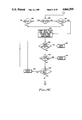
- FIG. 8A is a flow chart of the steps initiating a call instruction
- FIG. 8B is a flow chart of the steps of the call instruction initiated din FIG. 8A
- FIG. 8C is a flow chart of steps continuing the call instruction of FIG. 8B
- FIG. 8D is a flowchart of steps concluding the call instruction of FIG. 8C.
- FIG. 9 shows the state of stack segments after a procedure in ring 2 makes a call to a procedure in ring 0.
- FIG. 10 shows the state of stack segments after a return from a procedure in ring 0 to a procedure in ring 2.
- FIG. 11 shows the state of stack segments after a return from a procedure in ring 2 to a procedure in ring 3.
- FIG. 12 shows the state of the stack segments after a return from a procedure in ring 3 to a procedure in ring 3.
- FIG. 13A is a flow chart of charts for the steps initiating a return procedure
- FIG. 13B is a flow chart of steps continuing the return procedure of FIG. 13A
- FIG. 13C is a flowchart of steps concluding the return procedure of FIG. 13B, according to the present invention.
- FIG. 14 illustrates the trap context format according to the present invention.
- FIG. 15A is a flow chart of the steps initiating a trap procedure
- FIG. 15B is a flow chart of the steps continuing the trap procedure of FIG. 15A;
- FIG. 15C is a flowchart of the steps concluding the trap procedure of FIG. 15B, according to the present invention.
- the invention operates typically in a hardware system environment which is disclosed in U.S. Pat. No. 4,297,743, issued Oct. 27, 1981, and entitled "Call and Stack Mechanism for Procedures Executing in Different Rings".
- the envirionment is modified and enhanced by the invention which utilizes a call instruction or trap, along with the associated return instruction, and a new stack structure which supports both control as well as data storage.
- the procedure call is effected by hardware/firmware instructions and the hardware recognizable mechanism called the stack.”
- the invention has control storage support which is managed by the hardware.
- a control frame is acquired by the hardware whenever executing a call instruction or processing a trap condition. This control frame becomes the current frame and a base register is loaded with a pointer to the base of the current stack segment (which contains the current frame).
- the new stack mechanism (NS) has data storage support which is managed by software. Control information (for example, the return address of the calling procedure) is stored in the frame. The called or trap handling procedure can then elect to grow the frame if it needs data storage.
- the return instruction uses the control information to identify the calling procedure or the procedure that caused the trap, and once the return to the original procedure is accomplished, the entire frame used by the called procedure is released.
- a frame always contains control information, while the data storage may, or may not, be present.
- a processor may be unable to continue unambiguous execution of a currently executing program, for example upon detection of an error condition.
- a trap procedure must be invoked to execute a procedure to respond to the particular pre-established condition.
- the responding procedure may be a procedure that executes at a different (i.e., higher) level of privilege than the procedure for which the trap condition was identified.
- the trap procedure functions in a manner similar to the call instruction to insure that the procedure responding to the trap condition is indeed callable.
- the return instruction permits the return to the execution of the procedure interrupted by the trap condition.
- the processor logic element 1 is coupled to a virtual memory management unit (VMMU) 34, a cache memory 36 and a main memory by means of bus 32.
- the VMMU 34 translates a virtual address described in the instruction being executed into a physical address of the main memory 50.
- the virtual address includes a ring number, a segment number and a displacement.
- the VMMU 34 after translating the virtual address into a physical address, sends the physical address on bus 32 to the main memory 50 and directly from VMMU 34 to cache memoy 36.
- the VMMU 34 and cache memory 36 operations are implemented in a conventional manner.
- the instructions can operate on data in a multiplicity of formats and can include scientific instructions.
- a register file 2 includes a multiplicity of registers. A number of program visible registers of register file 2 can be loaded and ready by selected instructions.
- the registers of the register file 2 can include general word registers, address registers, double word operand register, control registers, scientific accumulators and a descriptor segment base register.
- the general word registers (R n ) are general registers and accumulators, and can be used as index registers.
- the address registers (B n ) are base registers, RDBR designates a remote descriptor base register and a register (T) can be the stack pointer.
- the double word operator registers (K n ) are general registers and accumulators and can be used for indexing.
- the control register (S) stores the process status security keys and stores the current security ring being processed.
- the processor 3 supports a number of rings, typically four.
- the rings are the mechanism to provide a secure data processing system. All software procedures consisting of operating system and application procedures execute in preassigned rings to insure protection between the procedures.
- a ring alarm register in register file 2 is examined during the execution of a return instruction.
- the descriptor base register defines the current process address space.
- the program counter 14 stores the address of the current instruction being executed and is normally incremented to point to the next instruction except when a jump or branch is indicated.
- An indicator register file 24 can include the basic operations (BOPS) indicator register 24-2, the commercial indicator register (CI) 24-4, and the scientific indicator register (SI) 24-6.
- a mode register file 26 includes BOPS mode registers 26-2, a commercial mode (CM) register 26-4 and a scientific mode register (SM) 26-6. The mode registers contain control information which is used during instruction execution.
- the program counter 14 is incremented to point to the location of the next instruction.
- the next instruction is received by the data-in unit 16 from the cache memory 36 over bus 32.
- the instruction is assembled in the instruction prefetch unit 18 and then transferred to branch unit 20.
- branch unit 20 the operation (OP) code is decoded, the status of the indicator registers 24 and the mode registers 26 is examined to determine whether special handling of the instruction is required.
- a next address logic 22 receives logic signals to generate a starting address. The starting address is sent to a read only store 38 over bus 42 to fetch the microword controlling the execution of the instruction by processor 3.
- the binary unit 11 which includes a binary arithmetic logic unit 4, a Q register 6 and a shifter 8 process binary and hexidecimal operands
- decimal unit 10 which includes a decimal arithmetic logic unit 10-6, a multiplier register 10-2 and a multiply read only memory 10-4, process decimal operands.
- An exponent unit 12 which includes an exponent register file 12-2 and an exponent arithmetic logic unit 12-4, processes the exponent portions of floating point operands.
- Bit O 201 is the New Stack Indicator (NS).
- N the New Stack Indicator
- the new call and return instructions are allowed and they will cause a frame to be acquired/relinquished in the appropritate stack segment of the new stack.
- a trap can also be mapped in a call and result in a frame being acquired in the appropriate stack segment of the new stack.
- this bit is set to O, then the new call and return instructions are not allowed and a program error trap is posted.
- Bit 1 202 is a new I/O indicator (NI). When this bit is set to 1, execution of I/O instructions requires new I/O handling.
- Bits 2 and 3 203 are reserved for hardware use (RHU).
- Bits 4-15 204 from the high order 12 bits of a 20 bit physical page frame address of a descriptor segment page table.
- the numerals (0:11) indicate that only bits 0-11 of the page frame number are in bit positions 4-15 of word 0.
- Word 1
- Bits 0-7 form the low order 8 bits of the 20-bit physical page frame address of the descriptor segment page table (DSPT).
- the numbers (12:19) indicate that only bits 12 through 19 of the page frame number are to be found in bits 0-7 of word 1.
- Bits 8-15 in an Offset Address that allows a page table to start on a modulo 4 word boundary.
- the numbers (0:7) indicate that the 8 bits of the offset are in bit positions 8 through 15 of word 1.
- Bits 0-1 207 are reserved for hardware use (RHU).
- Bits 2-9 208 form a Stack Base Address. This 8-bit field and the 2-bit R current define the segment number of the current stack segment when using the new stack mechanism NS. Word 3.
- Bits 0-5 210 are reserved for hardware use (RHU).
- Bits 6-15 211 is a Segment Descriptor Table Size. This field contains a 10-bit size field. When a virtual address (VA) is greater than the segment descriptor table size, then a segment trap results.
- VA virtual address
- FIG. 2B a typical ring in stack segment is shown. It should be noted that the stack segment is divided into a stack header, which is further subdivided into the portion of the stack segment which is for software use.
- a portion of the stack segment for hardware use stores a current frame pointer (CFP) 250 and a current frame length (CFL) 251.
- the current frame pointer CFP is shown in FIGS. 3A and 3B.
- FIG. 3A shows how the CFP is generated when referencing a wired stack segment.
- FIG. 3B shows how the CFP is generated when referencing a non-wired stack segment.
- a base address register (B4) points to the base of the stack segment following a call or trap.
- bits 0-1 301 store the ring number of the stack. (Note that since this is the wired stack segment, the value will always be 0).
- Bits 2-11 302 store a stack base address, stack base-1-CSS# (CSS# being the central processor number), which indicates the base where the ring 0 wired stack segment is located.
- Bits 12-31 303 indicate the displacement from the stack base where the current frame is located. (The current frame length CFL is a 32-bit unsigned integer whose value is CFL ⁇ 2 20 ; in the non-wired version the integer would be 230.)
- bits 0-1 304 and 10-11 306 store the ring number of the stack.
- the stack base is in bits 2-10. Bits 0-1 and bits 10-11 are concatenated to the stack base to arrive at the segment number for the stack segment of that particular ring.
- the displacement in bits 12-31 305 is the same as in FIG. 3A.
- Frame 1 of the ring n stack segment is divided into the link L 1 253, control storage CS 1 253 and data storage DS 1 254.
- the link is a pointer to the previous stack frame; link L 2 255 of Frame 2 points to L 1 252 of Frame 1.
- the control storage area CS 2 256 stores control information, such as, for example, the return address of the calling procedure.
- the data storage area DS 1 254 is optional and is utilized to store data that may be required by the called procedure.
- the Frame Current is the current frame being utilized by the called procedure and is divided into a link L 2 255 and control storage CS 2 256.
- the control storage performs the same function as any frame which stores control information.
- the new stack mechanism (NS) is a per-process stack to ensure isolation and thus protection among processes. Furthermore, the new stack mechanism (NS) is consistent with the concept of ring protection. Specifically the stack is subdivided into compartments in order to insure that the procedures may access only those compartments for which they are authorized. Since the virtual memory (VM) implementation defines the segment to be the unit of protection, the compartments referred to above are actually segments. It should be further noted that the NS also supports the concept of wired and non-wired stack segments. (A wired stack is always present in main memory; therefore when it is referenced no page fault will ever occur. A non-wired stack resides in virtual memory, and on a given reference a part of it may not be in main memory.)
- the wired stack is required because the procedures of a process actually consist of user and operating system (OS) procedures. Some of the OS procedures cannot tolerate page faults. They must use a wired stack segment. All other procedures will use the non-wired stack segments. To minimize the amount of wired space, one wired ring 0 stack segment per processor, rather than one wired ring 0 stack segment per process, is utilized. The wired ring 0 stack segment of processor n becomes the wired ring 0 stack segment of the process currently running on processor n.
- the NS is actually a stack that consists of n (one per processor) wired ring 0 stack segments and 3 consecutive non-wired stack segments (one each for rings 0, 1 and 2) and one or more consecutive, non-wired stack segments for ring 3.
- the stack base address of the wired ring 0 stack segment is obtained from Word 2 of the descriptor segment base register shown in FIG. 2A and stored (minus 1 minus CSS#) in bits 2-11 402 of the current frame pointer as shown in FIG. 4A. Since the frame pointer is generated by the hardware, the ring number stored in bits 0-1 401 is 0. Utilizing the segment number and the ring number, the wired ring 0 stack segment can be located. Finally the displacement address stored in bits 12-31 403 indicates the address of the required word in the ring 0 stack segment.
- FIG. 4B shows the format for addressing the non-wired stack segments 410 for rings 0 to 3. It is similar to the format for FIG. 4A except that the segment number is obtained from the stack base address stored in bits 2-9 405 and from the Ring Current RCR stored in bits 10-11 406.
- FIGS. 5 and 6 the state of three of the non-wired stack segments following initialization by the software and how the non-wired stack segments are managed by the hardware as a result of the call instruction is shown.
- FIG. 5 shows the state of the stack for a process currently executing in ring 3 which uses the stack frame called Frame Current 610 for its control and data information. It has been called from another procedure also operating in ring 3 with its stack frame indicated as Frame 1 610.
- Base address register B4 points to the CFP 606 in the Current stack segment base, which in turn contains a pointer 606A to the link word of the current frame 603, which in turn contains a pointer 604 to the link word of the previous frame 605.
- This chain of links from the current frame backwards allows the chain of procedure calls by which the current procedure was reached, to be traversed in the return direction when the current procedure is completed.
- the current frame pointer 606 in the ring 3 stack segment 650 provides a pointer to the link word for the topmost frame in that particular stack so that firmware can find this top frame any time the firmware procedure needs to identify this top frame .
- the ring 0 stack segment 652, and ring 2 stack segment 651 in FIG. 5 are both empty as noted by their current frame lengths being 0 in boxes 607 and 608. Empty ring stack segments will be normally the case for any procedure executing in the outer ring. Note that an empty stack segment may contain process state information in the software use area of the stack header. Process state information of long persistence, potentially for the life of the process, is expected to reside here.
- FIG. 6 shows the state of the stack a short time later after the procedure which was using the frame current in FIG. 6 has made a call to another procedure to be executed in ring 2.
- the stack frame that had been labelled Frame Current in FIG. 6 is now shown as frame 2 for the ring 3 stack segment in FIG. 5.
- Frame Current 631 has moved over into the ring 2 stack segment 651 because the called procedure is executing in ring 2.
- the link field for this frame 701 points back to the stack frame of the caller; i.e., to frame 2 620 of the ring 3 stack segment. Only control information 702 is shown for the Frame Current 631 in the ring 2 stack segment 651 since the called procedure has not acquired any data storage.
- the word 0 and word 1 750 of the frame contain the link address information.
- Word 2 751 contains the tag information.
- a portion 752A of word 3 of the call frame is reserved for software use, while a second portion 752B of the word 3 contains a copy of the indicator (I) register.
- Words 4 through 9 store the static link address (from a base address register) 753, the argument list address (from a base address register) 754 and the return address 755.
- the ring # is included in the return address to determine the privilege of the CGP.
- Words 10 and 11 756 store the contents of B4 from the CGP, words 12 and 13 757 store the procedure entry point address and words 14 and 15 758 store the contents of the K3 register.
- FIGS. 8A-8D the steps implementing the call instruction according to the present invention are shown via a sequence of flowcharts.
- This instruction is implemented using firmware techniques.
- the call instruction is utilized to specify a transfer of control from a calling procedure (CGP) to the called procedure (CDP).
- An effective address (EA) defines the CDP and its entry point.
- An R effective (REF) defines the effective execute privilege of the CDP.
- the call instruction is fetched and the effective address (EA) and REF are computed. See block 101. This determines the procedure to be called and the entry point of the procedure.
- the next step 102 determines whether or not the new stack functionality (NS) is enabled. When it is not enabled, the instruction is trapped as shown in box 103.
- NS new stack functionality
- the segment number specified in the effective address is utilized to fetch a segment descriptor for the segment which contains the procedure to be called during step 104.
- steps 105 and 107 checks are performed to ensure that no page faults or traps occur while performing this function.
- step 109 a check is made that determines whether the execute bit E of the called segment (procedure) is ON. When bit E is not ON a trap #14 (in step 111) is posted. In step 112, a check is made to determine whether the compatibility bit C of the segment descriptor is ON. When bit C is on, then a trap #14 of step 111 is posted. When bit C is not ON, go the next step 113 in FIG. 8B.
- FIG. 8B there is shown a flowchart that shows the checks that must be performed to determine whether a call is indeed possible. Three possibilities can occur. One, the call is successful and no ring change takes place. Two, the call is successful and a ring change takes place. Three the call is not allowed. When the called and calling procedures are peer procedures; i.e., have the same execute privilege, then the call will be successful and no ring change takes place. This path is shown by steps 114, 116, 118 and 123. The tests are performed in steps 114 and 118, in this case, basically state that SD.R1 ⁇ REF ⁇ SD.R2 or that REF is within the execute bracket of the called procedure.
- steps 114, 116, 118, 117, 119, 120, 121 and 122 When the call is not successful, then the path through steps 114, 116, 118 and 117 will terminate at any of the following steps, 125, 126, 127, or 128.
- the tests performed in steps 114 and 118 in this case, basically state that SD.R2 ⁇ REF or that REF is not within the execute bracket of the called procedure and that the following conditions must be met to successfully complete the call.
- Step 117 determines whether or not the calling procedure is outside the call bracket of the called procedure.
- the call bracket is the range of ring numbers in which a calling procedure must be executing in order to call the called procedure.
- step 119 there is a check made to determine whether the called procedure is a gate procedure. (A gate procedure is required in this case because the calling procedure, although within the call bracket of the called procedure, is not within the execute bracket of the called procedure and thus may enter the called procedure only through the gate.)
- step 119 a check is made to determine whether the gate bit of the segment descriptor is a 1.
- step 120 is entered.
- the gate bit is not a 1
- a trap 126 is taken which indicates that the called procedure is not in a gate segment.
- step 120 a check is made to determine whether the displacement of the Effective Address is within the gate array. (A gate array enumerates the entry points of the procedure segment in order to insure that control is not transferred to the procedure via an inward ring crossing call at a location other than at one of the entry points).
- step 121 a check is performed to determine whether the effective address EA is an even address to insure that a pointing to the first word of a pointer which points to the called procedure.
- a trap 128 is entered.
- an inward ring crossing is performed as shown on step 122.
- step 114 When the called procedure is less privileged than the calling procedure, then the call is not allowed as this would result in an outward call attempt.
- This path is shown by steps 114 and 124.
- the test performed in step 114 in this case, basically states that REF ⁇ SD.R1 or that REF is more privileged than the execute bracket of the called procedure.
- step 116 states that privilege was lost during the computation of REF since REF is less privileged than RCR.
- step 115 is required to insure that the original (RCR) privilege of the calling procedure is not more privileged than the lowest privilege of the called procedure (SD.R2).
- SD.R2 lowest privilege of the called procedure
- trap 30 the call/return trace is initiated in step 132.
- CFP current frame pointer
- CUSS current stack segment
- the current ring number RCR is used to compute the virtual address VA of the current stack segment CUSS.
- the CUSS contains the current frame which belongs to the calling procedure CGP.
- the header of the CUSS contains the current frame pointer CFP.
- the CFP is the value on the link to be stored in the call frame. See step 149 and FIG. 2. Steps 136 and 138 determine whether or not a page fault or trap was detected.
- step 142 the virtual address VA of the target stack segment TSS is computed in order to be able to fetch its current frame pointer Cfp and the current frame length CFL. See also FIG. 2.
- step 143 the R effective REF, the CSS# and the level # are utilized to find out where the target stack segment is by computing the virtual address of the target stack segment base. The first four words of the target stack segment containing the current frame pointer and the current frame length is read. These are utilized to compute the address of a new frame.
- steps 145 and 147 a check is made for page faults and traps to insure that the operation can be successfully completed.
- R effective REF and R current RCR are equal, then the new call frame is being placed in the same stack segment which is the current stack segment and checks are performed to insure the integrity of the stack shown in step 149.
- the stack's integrity is insured when the current frame length CFL stored in the header of the stack segment is not equal to 0.
- REF is not equal to RCR as determined in step 410, there is an indication that an inward ring change is necessary and two different stack segments are involved, the current stack segment and the target stack segment.
- step 154 the link is fetched from the TSS using the current frame pointer.
- step 152 is entered where a final check on the integrity of the stack is made. Accordingly, a new frame is placed in the target stack segment.
- the format of this target stack segment requires that the LINK pointed to by the current pointer be null.
- the call frame is stored in the target stack segment and the target stack segment's header is updated.
- the virtual address or the called frame is computed using the current frame pointer CFP and the current frame length CFL.
- the call context is stored in the call frame in step 162. (A call context is information that indicates the state of a procedure when it was entered and is used to allow that procedure to access arguments passed to it and restore as necessary the processor state upon return to the calling procedure.)
- step 163 and 164 a check is made to determine whether a page fault or trap was detected. Once this has been performed, the current frame pointer is updated with the virtual address of the call frame base and the current frame length CFL is set as required in step 165. In step 166 a determination is made whether or not a trap was detected. When there was a stack fault, step 167, results otherwise the next step E is entered.
- the trace trap disable key in M6.CS is reset by entering 0 therein in step 169 and step 170.
- the virtual address VA of the base of TSS (which contains the call frame) is entered in register B4 (as shown) in step 171.
- the R effective REF is then loaded into the ring number field of the procedure pointer register P.RN. See step 172.
- the effective address EA (EA.SN and EA.DSP) is loaded into the procedure pointer register P.
- step 174 the call procedure execution is started.
- the state of the stack segments is shown after a procedure executing in ring 2 makes a call to a procedure executing in ring 0.
- the procedure executing in ring 0 (the called procedure) becomes the current procedure and frame 4 950 becomes the current frame.
- B4 points to the base 905 of the ring 0 stack segment 652 and the link location 901 of the current frame references the frame 3 link location 701, the link location 701 of the calling procedure.
- the remainder of the stack segments remain the same as in FIG. 7.
- the resulting state is shown in FIG. 10.
- frame 4 950 is released and frame 3 951 becomes the current frame.
- the procedure that had called the ring 0 procedure becomes the current procedure.
- the ring 0 header 952 is updated such that the current frame length (CFL) location 608 is set equal to zero and the CFP location 905 is made to point to a null entry which replaces the link in location 901.
- the return instruction is utilized to specify a transfer of control from the called procedure (CDP) to the calling procedure (CGP).
- the return instruction is implemented using firmware techniques to preserve the integrity of the procedures.
- the return instruction is fetched in step 1301.
- DSBR.NS new stack
- the return instruction is executed, using the contents of the current stack frame in the current stack segment (CUSS).
- the current stack segment can be a per processor wired ring 0 or can be a non-wired stack segment.
- the virtual address (VA) of the current frame pointer (CFP) in current stack segment (CUSS) is computed and fetched.
- step 1306 a test is performed to determine whether a page fault has been detected. When a page fault is detected, then the program executes a page fault procedure in step 1307. When a page fault is not detected, then a test is made, in step 1308, to determine whether a trap condition has been detected. When a trap condition has been detected, then a stack fault routine is entered step 1309, otherwise, the execution of the return instruction is continued.
- step 1317 the return address supplies the ring effective number (REF), the effective address segment number (EA.SN) and the effective address displacement (EA.DSP).
- step 1318 using the segment number of the effective address (EA), the segment descriptor (SD) for this segment is fetched.
- step 1319 a test is performed to determine whether a page fault has been detected. When a page fault is detected, then a page fault procedure of step 1320 is instituted. When a page fault was not detected, a test is performed to determine whether a trap has been detected. When a trap is detected, then a trap procedure 1322 is instituted, otherwise, the return instruction is continued.
- an access violation trap routine is performed in step 1325.
- step 13B when the SD.C is not on then the determination is made in step 1327 when the ring effective number (REF) is within the execute bracket of the calling procedure, i.e. SD.R1 ⁇ REF ⁇ SD.R2.
- a trap routine in step 1328, is initiated. Otherwise, a determination is made whether or not the ring effective number (REF) is greater than or equal to the original privilege level (RCR) in step 1329.
- RCR original privilege level
- step 1330 When this condition is not met, then a trap routine in step 1330 is initiated.
- step 1335 The determination is made when the contents of the ring alarm register are zero in step 1335. When the contents of the ring alarm register are not zero, then in step 1336, the determination is made whether the contents of the ring alarm register are less than or equal to the ring effective number. When the condition tested in step 1336 is true, then a trap procedure is entered in step 1337. When the result of steps 1335 and 1336 are false, then in step 1338 including steps 1339 and 1344, the return instruction context is retrieved and stored in temporary registers. This is done in step 1339, using the current frame pointer, to fetch from the current frame a copy of the indicator register (I), B4 and K3.
- steps 1340 and 1342 a determination is made whether a page fault or a trap has been detected and, if so, an appropriate routine is entered in step 1341 or in step 1343.
- step 1344 the current context from appropriate registers is saved in the temporary registers.
- step 1346 the determination is made when the original privilege level (RCR) is equal to the ring effective number (REF).
- RCR original privilege level
- REF ring effective number
- the current stack segment header is updated by setting the current frame link to zero and setting the link pointed to by the current frame pointer to null.
- the length of the previous frame in current segment stack is calculated using the link and its address.
- the current segment stack header is updated by storing the contents of the link field in the current frame pointer and placing the length of the previous frame in the current frame length field.
- step 1350 the occurrence of a page fault or of a trap is determined in step 1350 and step 1352 and an appropriate routine is entered in step 1351 or in step 1353.
- step 1355 the trace trap is reset by disabling the key in M6.RS.
- step 1357 the return context is restored to the following processor registers, indicator register I, the base address register B4 and the double word operand register K3.
- step 1363 a determination is made to determine whether the return causes a ring change. When a ring change occurs, then the ring numbers of all the base registers are set to the least privilege of REF and the base register ring number in step 1364. When there is no ring change, th ring numbers of all the base registers (RN) are not changed. The ring effective number (REF) is entered in P.RN, the pointer register ring number step 1358.
- step 1359 the return address defined by the segment number of the effective address (EA.SN) and the displacement of the effective address (EA.DPS) is entered into the equivalent fields (P.SN) and (P.DPS) of the procedure register.
- step 1360 the procedure to which control is being returned is initiated with the privilege level defined by procedure register ring number (P.RN).
- the word 0 and 1 locations 1401 of the trap stack frame 1400 contain the link pointer.
- the word 3 location 1403 contains the associated trap number and a copy of the indicator register I.
- the subsequent word 4 location 1404 includes a copy of the first word of the instruction.
- the word 5, 6 and 7 locations 1405 contain miscellaneous information and an address respectively.
- the word 8 and 9 locations 1406 include the contents of the procedure counter.
- the word 10 and 11 locations 1407 store the contents of the B4 register, while the word 12 and 13 locations 1408 store the address of the entry point of the procedure handling the trap.
- word locations 14 and 15 1409 of the stack store the contents of the K3 register.
- the hardware functions for responding to a trap condition are illustrated.
- the hardware functions are similar to those invoked during the execution of a call instruction, the only difference being that in the case of a trap, the trap condition determines the called procedure (or trap handler) while in the case of a call instruction, the call instruction identifies the called procedure.
- the appropriate trap number is assigned to the trap.
- the determination is made whether or not the trap number is one of a preselected group of trap numbers. When the trap number is one of those, then the hardware must undo the instruction in step 1504 so that the instruction may be retried once the trap condition is resolved.
- step 1504 the processor processing the trap determines its processor identifying number.
- step 1507 the processor identifying number and the trap identifying number are used to compute the virtual address of the trap vector and the trap vector is retrieved.
- step 1508 a determination is made as whether a page fault or a trap has been encountered. When true, then a software fault routine is entered. Otherwise, the trap procedure continues.
- step 1511 When the contents of the trap vector location are null in step 1511, then a software fault procedure is instituted. When the trap vector contents are not null, then in step 1513, the segment descriptor for this segment is retrieved using the segment number of the trap vector. A page fault and a trap are tested in steps 1514 and 1516. When a page fault or a trap is detected, then a page fault (step 1515) or a software fault procedure (1516) is initiated. Otherwise, the ring effective number is chosen to be the maximum (least privileged) of the trap vector ring number or the current privilege level, in step 1518. The next sequence of steps uses the segment descriptor of the segment containing the trap handler to determine whether the trap handler is callable and to compute the ring effective number (1519).
- the trap procedure determines whether or not a ring crossing occurs in steps 1523, 1524, and 1527 or whether no ring crossing occurs in steps 1523, 1524, 1525 and 1528.
- the determination is made whether the ring effective number is less than the R1 field of the segment descriptor in step 1523. When the determination is positive, then the software fault procedure (1526) is invoked. Otherwise, the the determination is made whether the ring effective number (REF) is greater than the original privilege in step 1524. When the ring effective number is greater than the original privilege, then the determination is made in step 1525 whether the R2 field of the segment descriptor is greater than original privilege. When the test is positive, then the software fault procedure 1526 is invoked.
- step 1524 When the determination in step 1524 is negative, then the test is made in step 1527 whether the ring effective number is greater than the R2 field of the segment descriptor. When the determination in step 1525 is negative or the determination of step 1527 is positive, then the determination is made whether the ring effective number is greater than the R3 field of the segment descriptor. When the answer is positive, then the software fault procedure is invoked. Otherwise, in step 1530, an inward ring crossing is performed, letting the ring effective number equal the R2 field of the segment descriptor. When the determination of step 1527 is negative, then no ring crossing is performed, and the procedure is executed at the ring specified by the ring effective number.
- step 1532 indicates that the following steps of the procedure describe how a trap frame is acquired in the appropriate stack segment of the new stack, i.e. the per processor wired ring 0 stack segment or a non-wired stack segment.
- Step 1533 indicates that the following steps compute the link of the trap frame by reading the current frame pointer in the current stack segment.
- step 1534 the virtual address of the current frame pointer in the current stack segment is computed using the level number, the current processor number and the original privilege and the current frame pointer is retrieved.
- step 1535 the detection of whether a page fault has been detected is made and in step 1537, the determination of whether a trap has been detected is made. These determinations result in a page fault procedure (1536) or in a stack fault procedure (1538).
- FIG. 15B shows how to compute the virtual address of the target stack segment (the stack segment which will receive the trap frame) in order to be able to retrieve its current frame pointer and the current frame length as stated in step 1541.
- the virtual address of the base of the trap stack segment is computed using the privilege level number, the current processor number and the ring effective privilege.
- the first four words of the target stack segment (the current frame pointer and the current frame length) are retrieved.
- step 1543 the presence of a page fault is determined, while in step 1545, the presence of a trap condition was determined. The presence of either condition results in a page fault procedure (1544) and a stack fault procedure (1546) respectively.
- Steps 1547 through 1555 are performed to check the integrity of the stack structure.
- step 1547 the condition, the ring effective number equals current ring number, is tested.
- the condition in step 1549 is true, i.e., the current frame length in the target stack segment header is equal 0, then a stack structure error exists and a stack fault procedure 1556 is initiated. Otherwise the trap procedure can continue.
- the test for a page fault and a trap condition are made in steps 1551 and 1553. In step 1555, the condition does the link in target stack segment equal null is tested. When the test in step 1555 is negative, then the stack fault procedure is initiated, otherwise the trap procedure continues.
- step 1558 indicates that the trap frame is to be stored in the target stack segment and that the header of the target stack segment is to be updated.
- step 1559 the virtual address of the trap frame base is calculated using the current frame pointer and the current frame length.
- the trap context is stored in the trap frame (and access right checks are performed).
- step 1561 the presence of a page fault is determined and in step 1563, the presence of a trap condition is tested.
- step 1565 the current frame pointer is updated with the virtual address of the trap frame base and the current frame length is set as required.
- step 1566 the presence of a trap condition was tested.
- the virtual address of the base of the target segment stack (which contains the trap frame is entered in base address register B4 (and the ring number of B4 is set to the effective ring number REF) in step 1568, in step 1569, the R effective is placed in the ring field of the procedure pointer register P.RN.
- the effective address EA (EA.SN and EA.DSP) is loaded into the procedure pointer register P.
- the trap handler execution is started at the level defined in P.RN.
Abstract
Description
Claims (5)
Priority Applications (1)
| Application Number | Priority Date | Filing Date | Title |
|---|---|---|---|
| US06/944,494 US4866599A (en) | 1985-06-27 | 1986-12-19 | Call instruction, return instruction and trap procedure for ring crossing architecture |
Applications Claiming Priority (2)
| Application Number | Priority Date | Filing Date | Title |
|---|---|---|---|
| US06/749,245 US4703417A (en) | 1985-06-27 | 1985-06-27 | Call instruction for ring crossing architecture |
| US06/944,494 US4866599A (en) | 1985-06-27 | 1986-12-19 | Call instruction, return instruction and trap procedure for ring crossing architecture |
Related Parent Applications (1)
| Application Number | Title | Priority Date | Filing Date |
|---|---|---|---|
| US06/749,245 Continuation-In-Part US4703417A (en) | 1985-06-27 | 1985-06-27 | Call instruction for ring crossing architecture |
Publications (1)
| Publication Number | Publication Date |
|---|---|
| US4866599A true US4866599A (en) | 1989-09-12 |
Family
ID=27115080
Family Applications (1)
| Application Number | Title | Priority Date | Filing Date |
|---|---|---|---|
| US06/944,494 Expired - Lifetime US4866599A (en) | 1985-06-27 | 1986-12-19 | Call instruction, return instruction and trap procedure for ring crossing architecture |
Country Status (1)
| Country | Link |
|---|---|
| US (1) | US4866599A (en) |
Cited By (22)
| Publication number | Priority date | Publication date | Assignee | Title |
|---|---|---|---|---|
| US5023773A (en) * | 1988-02-10 | 1991-06-11 | International Business Machines Corporation | Authorization for selective program access to data in multiple address spaces |
| US5051894A (en) * | 1989-01-05 | 1991-09-24 | Bull Hn Information Systems Inc. | Apparatus and method for address translation of non-aligned double word virtual addresses |
| US5113521A (en) * | 1988-03-18 | 1992-05-12 | Digital Equipment Corporation | Method and apparatus for handling faults of vector instructions causing memory management exceptions |
| US5117491A (en) * | 1989-03-31 | 1992-05-26 | Bull Hn Information Systems Inc. | Ring reduction logic using parallel determination of ring numbers in a plurality of functional units and forced ring numbers by instruction decoding |
| US6158024A (en) * | 1998-03-31 | 2000-12-05 | International Business Machines Corporation | Method and apparatus for structured memory analysis of data processing systems and applications |
| US6253317B1 (en) * | 1997-01-09 | 2001-06-26 | Sun Microsystems, Inc. | Method and apparatus for providing and handling traps |
| US6546548B1 (en) | 1997-12-12 | 2003-04-08 | International Business Machines Corporation | Method and system for compensating for output overhead in trace data using initial calibration information |
| US6560773B1 (en) | 1997-12-12 | 2003-05-06 | International Business Machines Corporation | Method and system for memory leak detection in an object-oriented environment during real-time trace processing |
| US6564276B1 (en) * | 2000-01-25 | 2003-05-13 | Dell Usa L.P. | Access restriction of environmental circuits |
| US20030101380A1 (en) * | 2001-11-29 | 2003-05-29 | Microsoft Corporation | Method and system for rewriting unwind data in the presence of exceptions |
| US6662358B1 (en) | 1997-12-12 | 2003-12-09 | International Business Machines Corporation | Minimizing profiling-related perturbation using periodic contextual information |
| US6728949B1 (en) | 1997-12-12 | 2004-04-27 | International Business Machines Corporation | Method and system for periodic trace sampling using a mask to qualify trace data |
| US6732357B1 (en) | 1997-12-12 | 2004-05-04 | International Business Machines Corporation | Determining and compensating for temporal overhead in trace record generation and processing |
| US6751789B1 (en) | 1997-12-12 | 2004-06-15 | International Business Machines Corporation | Method and system for periodic trace sampling for real-time generation of segments of call stack trees augmented with call stack position determination |
| US20050010930A1 (en) * | 2003-07-11 | 2005-01-13 | Vaught Jeffrey A. | System and method for high-performance profiling of application events |
| US20070220612A1 (en) * | 2006-03-14 | 2007-09-20 | Proton World International N.V. | Protection of a program against a trap |
| US20090328231A1 (en) * | 2006-07-20 | 2009-12-31 | Gemalto Sa | Method of dynamic protection of data during the execution of a software code in intermediate language in a digital apparatus |
| WO2010004240A1 (en) * | 2008-07-10 | 2010-01-14 | Cambridge Consultants Limited | Data processing apparatus, for example using modes |
| US20100293342A1 (en) * | 2007-04-10 | 2010-11-18 | Morfey Alistair G | Data processing apparatus |
| US20110225402A1 (en) * | 2010-03-15 | 2011-09-15 | Arm Limited | Apparatus and method for handling exception events |
| GB2500844A (en) * | 2010-03-15 | 2013-10-02 | Advanced Risc Mach Ltd | Selecting either base level or further level stack when processing data in current further level exception state above base level |
| US9519773B2 (en) | 2014-09-12 | 2016-12-13 | Intel Corporation | Returning to a control transfer instruction |
Citations (5)
| Publication number | Priority date | Publication date | Assignee | Title |
|---|---|---|---|---|
| US3916385A (en) * | 1973-12-12 | 1975-10-28 | Honeywell Inf Systems | Ring checking hardware |
| US4104718A (en) * | 1974-12-16 | 1978-08-01 | Compagnie Honeywell Bull (Societe Anonyme) | System for protecting shared files in a multiprogrammed computer |
| US4177510A (en) * | 1973-11-30 | 1979-12-04 | Compagnie Internationale pour l'Informatique, CII Honeywell Bull | Protection of data in an information multiprocessing system by implementing a concept of rings to represent the different levels of privileges among processes |
| US4297743A (en) * | 1973-11-30 | 1981-10-27 | Compagnie Honeywell Bull | Call and stack mechanism for procedures executing in different rings |
| US4524416A (en) * | 1980-04-15 | 1985-06-18 | Honeywell Information Systems Inc. | Stack mechanism with the ability to dynamically alter the size of a stack in a data processing system |
-
1986
- 1986-12-19 US US06/944,494 patent/US4866599A/en not_active Expired - Lifetime
Patent Citations (5)
| Publication number | Priority date | Publication date | Assignee | Title |
|---|---|---|---|---|
| US4177510A (en) * | 1973-11-30 | 1979-12-04 | Compagnie Internationale pour l'Informatique, CII Honeywell Bull | Protection of data in an information multiprocessing system by implementing a concept of rings to represent the different levels of privileges among processes |
| US4297743A (en) * | 1973-11-30 | 1981-10-27 | Compagnie Honeywell Bull | Call and stack mechanism for procedures executing in different rings |
| US3916385A (en) * | 1973-12-12 | 1975-10-28 | Honeywell Inf Systems | Ring checking hardware |
| US4104718A (en) * | 1974-12-16 | 1978-08-01 | Compagnie Honeywell Bull (Societe Anonyme) | System for protecting shared files in a multiprogrammed computer |
| US4524416A (en) * | 1980-04-15 | 1985-06-18 | Honeywell Information Systems Inc. | Stack mechanism with the ability to dynamically alter the size of a stack in a data processing system |
Cited By (37)
| Publication number | Priority date | Publication date | Assignee | Title |
|---|---|---|---|---|
| US5023773A (en) * | 1988-02-10 | 1991-06-11 | International Business Machines Corporation | Authorization for selective program access to data in multiple address spaces |
| US5113521A (en) * | 1988-03-18 | 1992-05-12 | Digital Equipment Corporation | Method and apparatus for handling faults of vector instructions causing memory management exceptions |
| US5051894A (en) * | 1989-01-05 | 1991-09-24 | Bull Hn Information Systems Inc. | Apparatus and method for address translation of non-aligned double word virtual addresses |
| US5117491A (en) * | 1989-03-31 | 1992-05-26 | Bull Hn Information Systems Inc. | Ring reduction logic using parallel determination of ring numbers in a plurality of functional units and forced ring numbers by instruction decoding |
| US6253317B1 (en) * | 1997-01-09 | 2001-06-26 | Sun Microsystems, Inc. | Method and apparatus for providing and handling traps |
| US6662358B1 (en) | 1997-12-12 | 2003-12-09 | International Business Machines Corporation | Minimizing profiling-related perturbation using periodic contextual information |
| US6754890B1 (en) | 1997-12-12 | 2004-06-22 | International Business Machines Corporation | Method and system for using process identifier in output file names for associating profiling data with multiple sources of profiling data |
| US6560773B1 (en) | 1997-12-12 | 2003-05-06 | International Business Machines Corporation | Method and system for memory leak detection in an object-oriented environment during real-time trace processing |
| US6546548B1 (en) | 1997-12-12 | 2003-04-08 | International Business Machines Corporation | Method and system for compensating for output overhead in trace data using initial calibration information |
| US6728949B1 (en) | 1997-12-12 | 2004-04-27 | International Business Machines Corporation | Method and system for periodic trace sampling using a mask to qualify trace data |
| US6732357B1 (en) | 1997-12-12 | 2004-05-04 | International Business Machines Corporation | Determining and compensating for temporal overhead in trace record generation and processing |
| US6751789B1 (en) | 1997-12-12 | 2004-06-15 | International Business Machines Corporation | Method and system for periodic trace sampling for real-time generation of segments of call stack trees augmented with call stack position determination |
| US6158024A (en) * | 1998-03-31 | 2000-12-05 | International Business Machines Corporation | Method and apparatus for structured memory analysis of data processing systems and applications |
| US6564276B1 (en) * | 2000-01-25 | 2003-05-13 | Dell Usa L.P. | Access restriction of environmental circuits |
| US20030101380A1 (en) * | 2001-11-29 | 2003-05-29 | Microsoft Corporation | Method and system for rewriting unwind data in the presence of exceptions |
| US7426719B2 (en) * | 2001-11-29 | 2008-09-16 | Microsoft Corporation | Method and system for rewriting unwind data in the presence of exceptions |
| US20050010930A1 (en) * | 2003-07-11 | 2005-01-13 | Vaught Jeffrey A. | System and method for high-performance profiling of application events |
| US7984129B2 (en) * | 2003-07-11 | 2011-07-19 | Computer Associates Think, Inc. | System and method for high-performance profiling of application events |
| US8504674B2 (en) | 2003-07-11 | 2013-08-06 | Ca, Inc. | System and method for high-performance profiling of application events |
| US20070220612A1 (en) * | 2006-03-14 | 2007-09-20 | Proton World International N.V. | Protection of a program against a trap |
| US7822953B2 (en) * | 2006-03-14 | 2010-10-26 | Proton World International N.V. | Protection of a program against a trap |
| US20090328231A1 (en) * | 2006-07-20 | 2009-12-31 | Gemalto Sa | Method of dynamic protection of data during the execution of a software code in intermediate language in a digital apparatus |
| US8646092B2 (en) * | 2006-07-20 | 2014-02-04 | Gemalto Sa | Method of dynamic protection of data during the execution of a software code in intermediate language in a digital apparatus |
| US20100293342A1 (en) * | 2007-04-10 | 2010-11-18 | Morfey Alistair G | Data processing apparatus |
| US9652241B2 (en) | 2007-04-10 | 2017-05-16 | Cambridge Consultants Ltd. | Data processing apparatus with instruction encodings to enable near and far memory access modes |
| WO2010004240A1 (en) * | 2008-07-10 | 2010-01-14 | Cambridge Consultants Limited | Data processing apparatus, for example using modes |
| US9645949B2 (en) | 2008-07-10 | 2017-05-09 | Cambridge Consultants Ltd. | Data processing apparatus using privileged and non-privileged modes with multiple stacks |
| GB2478733B (en) * | 2010-03-15 | 2013-08-14 | Advanced Risc Mach Ltd | Apparatus and method for handling exception events |
| GB2500844A (en) * | 2010-03-15 | 2013-10-02 | Advanced Risc Mach Ltd | Selecting either base level or further level stack when processing data in current further level exception state above base level |
| GB2478733A (en) * | 2010-03-15 | 2011-09-21 | Advanced Risc Mach Ltd | Stack management with multiple levels of exception |
| GB2500844B (en) * | 2010-03-15 | 2014-03-12 | Advanced Risc Mach Ltd | Apparatus and method for handling exception events |
| US8677107B2 (en) | 2010-03-15 | 2014-03-18 | Arm Limited | Apparatus and method for handling exception events |
| US9104425B2 (en) | 2010-03-15 | 2015-08-11 | Arm Limited | Apparatus and method for handling exception events |
| US20110225402A1 (en) * | 2010-03-15 | 2011-09-15 | Arm Limited | Apparatus and method for handling exception events |
| US9727343B2 (en) | 2010-03-15 | 2017-08-08 | Arm Limited | Apparatus and method for handling exception events |
| US9519773B2 (en) | 2014-09-12 | 2016-12-13 | Intel Corporation | Returning to a control transfer instruction |
| TWI582635B (en) * | 2014-09-12 | 2017-05-11 | 英特爾股份有限公司 | Returning to a control transfer instruction |
Similar Documents
| Publication | Publication Date | Title |
|---|---|---|
| US4866599A (en) | Call instruction, return instruction and trap procedure for ring crossing architecture | |
| KR860000838B1 (en) | Improved memory proterction system using capability registers | |
| US5157777A (en) | Synchronous communication between execution environments in a data processing system employing an object-oriented memory protection mechanism | |
| US7467271B2 (en) | Operating system permitting limited access to a system page | |
| CA2024444C (en) | Process using virtual addressing in a non-privileged instruction to control the copying of a page of data in or between multiple media | |
| US4945480A (en) | Data domain switching on program address space switching and return | |
| US5280614A (en) | Apparatus and method for controlling access to data using domains | |
| US4979098A (en) | Multiple address space token designation, protection controls, designation translation and lookaside | |
| US5075842A (en) | Disabling tag bit recognition and allowing privileged operations to occur in an object-oriented memory protection mechanism | |
| US3916385A (en) | Ring checking hardware | |
| US3938096A (en) | Apparatus for developing an address of a segment within main memory and an absolute address of an operand within the segment | |
| EP0213843A2 (en) | Digital processor control | |
| EP0026589A2 (en) | Multi-programming data processing system process suspension | |
| JPH08278886A (en) | Method and system for operation of extended system management in data-processing system | |
| JPS5911943B2 (en) | Trap mechanism for data processing equipment | |
| JPS6248258B2 (en) | ||
| US4703417A (en) | Call instruction for ring crossing architecture | |
| KR850000622B1 (en) | Data processing system including internal register addressing arrangements | |
| JPS6017135B2 (en) | data processing equipment | |
| JPH05210593A (en) | Memory partitioning device for microprocessor and method of loading segment descriptor to segment-register | |
| JP2001249848A (en) | Privileged advancement based on precedent privilege level | |
| JP3554320B2 (en) | A data processing system that performs communication between execution environments in a data processing system employing an object-oriented memory protection mechanism | |
| CN115885266A (en) | Label inspection device and method | |
| GB1585960A (en) | Information flow security mechanisms for data processing systems | |
| CA1308202C (en) | Access register translation means for address generating mechanism for multiple virtual spaces |
Legal Events
| Date | Code | Title | Description |
|---|---|---|---|
| AS | Assignment |
Owner name: HONEYWELL INFORMATION SYSTEM INC., HONEYWELL PLAZA Free format text: ASSIGNMENT OF ASSIGNORS INTEREST.;ASSIGNORS:MORGANTI, VICTOR M.;PRANGE, PATRICK E.;REEL/FRAME:004655/0553 Effective date: 19861219 Owner name: HONEYWELL INFORMATION SYSTEM INC., A CORP. OF DE., Free format text: ASSIGNMENT OF ASSIGNORS INTEREST;ASSIGNORS:MORGANTI, VICTOR M.;PRANGE, PATRICK E.;REEL/FRAME:004655/0553 Effective date: 19861219 |
|
| FEPP | Fee payment procedure |
Free format text: PAYER NUMBER DE-ASSIGNED (ORIGINAL EVENT CODE: RMPN); ENTITY STATUS OF PATENT OWNER: LARGE ENTITY Free format text: PAYOR NUMBER ASSIGNED (ORIGINAL EVENT CODE: ASPN); ENTITY STATUS OF PATENT OWNER: LARGE ENTITY |
|
| STCF | Information on status: patent grant |
Free format text: PATENTED CASE |
|
| FPAY | Fee payment |
Year of fee payment: 4 |
|
| FPAY | Fee payment |
Year of fee payment: 8 |
|
| FEPP | Fee payment procedure |
Free format text: PAYER NUMBER DE-ASSIGNED (ORIGINAL EVENT CODE: RMPN); ENTITY STATUS OF PATENT OWNER: LARGE ENTITY Free format text: PAYOR NUMBER ASSIGNED (ORIGINAL EVENT CODE: ASPN); ENTITY STATUS OF PATENT OWNER: LARGE ENTITY |
|
| REFU | Refund |
Free format text: REFUND - PAYMENT OF MAINTENANCE FEE, 8TH YEAR, LARGE ENTITY (ORIGINAL EVENT CODE: R184); ENTITY STATUS OF PATENT OWNER: LARGE ENTITY |
|
| FPAY | Fee payment |
Year of fee payment: 12 |