US4900759A - Phenolic foams - Google Patents
Phenolic foams Download PDFInfo
- Publication number
- US4900759A US4900759A US07/176,463 US17646388A US4900759A US 4900759 A US4900759 A US 4900759A US 17646388 A US17646388 A US 17646388A US 4900759 A US4900759 A US 4900759A
- Authority
- US
- United States
- Prior art keywords
- foam
- resole
- pressure
- watts
- closed
- Prior art date
- Legal status (The legal status is an assumption and is not a legal conclusion. Google has not performed a legal analysis and makes no representation as to the accuracy of the status listed.)
- Expired - Lifetime
Links
- 239000006260 foam Substances 0.000 title claims abstract description 219
- ISWSIDIOOBJBQZ-UHFFFAOYSA-N phenol group Chemical group C1(=CC=CC=C1)O ISWSIDIOOBJBQZ-UHFFFAOYSA-N 0.000 title claims abstract description 33
- 229920003987 resole Polymers 0.000 claims description 122
- 239000000203 mixture Substances 0.000 claims description 79
- 239000004094 surface-active agent Substances 0.000 claims description 51
- 239000004604 Blowing Agent Substances 0.000 claims description 50
- WSFSSNUMVMOOMR-UHFFFAOYSA-N Formaldehyde Chemical compound O=C WSFSSNUMVMOOMR-UHFFFAOYSA-N 0.000 claims description 45
- 238000000034 method Methods 0.000 claims description 33
- 230000009257 reactivity Effects 0.000 claims description 29
- 239000003377 acid catalyst Substances 0.000 claims description 15
- 150000003839 salts Chemical class 0.000 claims description 8
- YMWUJEATGCHHMB-UHFFFAOYSA-N Dichloromethane Chemical compound ClCCl YMWUJEATGCHHMB-UHFFFAOYSA-N 0.000 claims description 5
- 238000010438 heat treatment Methods 0.000 claims description 3
- 239000002736 nonionic surfactant Substances 0.000 claims description 3
- 238000010998 test method Methods 0.000 claims 2
- 238000009413 insulation Methods 0.000 abstract description 5
- 230000002411 adverse Effects 0.000 abstract description 3
- 230000006866 deterioration Effects 0.000 abstract 1
- 238000005187 foaming Methods 0.000 description 58
- 210000004027 cell Anatomy 0.000 description 46
- 239000002253 acid Substances 0.000 description 39
- 239000003054 catalyst Substances 0.000 description 35
- 238000001125 extrusion Methods 0.000 description 31
- MTHSVFCYNBDYFN-UHFFFAOYSA-N diethylene glycol Chemical compound OCCOCCO MTHSVFCYNBDYFN-UHFFFAOYSA-N 0.000 description 27
- XLYOFNOQVPJJNP-UHFFFAOYSA-N water Substances O XLYOFNOQVPJJNP-UHFFFAOYSA-N 0.000 description 27
- DDMOUSALMHHKOS-UHFFFAOYSA-N 1,2-dichloro-1,1,2,2-tetrafluoroethane Chemical compound FC(F)(Cl)C(F)(F)Cl DDMOUSALMHHKOS-UHFFFAOYSA-N 0.000 description 25
- 239000000306 component Substances 0.000 description 22
- 239000000123 paper Substances 0.000 description 22
- 230000008569 process Effects 0.000 description 22
- YXFVVABEGXRONW-UHFFFAOYSA-N Toluene Chemical compound CC1=CC=CC=C1 YXFVVABEGXRONW-UHFFFAOYSA-N 0.000 description 21
- MUBZPKHOEPUJKR-UHFFFAOYSA-N Oxalic acid Chemical compound OC(=O)C(O)=O MUBZPKHOEPUJKR-UHFFFAOYSA-N 0.000 description 18
- 229920005989 resin Polymers 0.000 description 17
- 239000011347 resin Substances 0.000 description 17
- 241000219492 Quercus Species 0.000 description 15
- 235000016976 Quercus macrolepis Nutrition 0.000 description 15
- 238000001723 curing Methods 0.000 description 14
- 238000009472 formulation Methods 0.000 description 14
- -1 alkyl phenols Chemical class 0.000 description 11
- 238000006243 chemical reaction Methods 0.000 description 11
- 238000004519 manufacturing process Methods 0.000 description 11
- 239000002655 kraft paper Substances 0.000 description 10
- 238000005481 NMR spectroscopy Methods 0.000 description 9
- 239000000758 substrate Substances 0.000 description 9
- 230000004888 barrier function Effects 0.000 description 8
- 230000015572 biosynthetic process Effects 0.000 description 8
- 238000005755 formation reaction Methods 0.000 description 8
- 238000012360 testing method Methods 0.000 description 8
- 238000011144 upstream manufacturing Methods 0.000 description 8
- 239000007789 gas Substances 0.000 description 7
- 239000000463 material Substances 0.000 description 7
- 230000035945 sensitivity Effects 0.000 description 7
- 239000000126 substance Substances 0.000 description 7
- 239000008096 xylene Substances 0.000 description 7
- XEEYBQQBJWHFJM-UHFFFAOYSA-N Iron Chemical compound [Fe] XEEYBQQBJWHFJM-UHFFFAOYSA-N 0.000 description 6
- 210000002421 cell wall Anatomy 0.000 description 6
- 230000000694 effects Effects 0.000 description 6
- 238000007667 floating Methods 0.000 description 6
- NBVXSUQYWXRMNV-UHFFFAOYSA-N fluoromethane Chemical compound FC NBVXSUQYWXRMNV-UHFFFAOYSA-N 0.000 description 6
- 238000006386 neutralization reaction Methods 0.000 description 6
- 235000006408 oxalic acid Nutrition 0.000 description 6
- 229920001296 polysiloxane Polymers 0.000 description 6
- 230000001681 protective effect Effects 0.000 description 6
- 238000012546 transfer Methods 0.000 description 6
- 239000000654 additive Substances 0.000 description 5
- 230000001419 dependent effect Effects 0.000 description 5
- 230000014759 maintenance of location Effects 0.000 description 5
- 150000003891 oxalate salts Chemical class 0.000 description 5
- AJDIZQLSFPQPEY-UHFFFAOYSA-N 1,1,2-Trichlorotrifluoroethane Chemical compound FC(F)(Cl)C(F)(Cl)Cl AJDIZQLSFPQPEY-UHFFFAOYSA-N 0.000 description 4
- LBLYYCQCTBFVLH-UHFFFAOYSA-N 2-Methylbenzenesulfonic acid Chemical compound CC1=CC=CC=C1S(O)(=O)=O LBLYYCQCTBFVLH-UHFFFAOYSA-N 0.000 description 4
- CURLTUGMZLYLDI-UHFFFAOYSA-N Carbon dioxide Chemical compound O=C=O CURLTUGMZLYLDI-UHFFFAOYSA-N 0.000 description 4
- QAOWNCQODCNURD-UHFFFAOYSA-N Sulfuric acid Chemical compound OS(O)(=O)=O QAOWNCQODCNURD-UHFFFAOYSA-N 0.000 description 4
- 238000004458 analytical method Methods 0.000 description 4
- 230000005587 bubbling Effects 0.000 description 4
- AXCZMVOFGPJBDE-UHFFFAOYSA-L calcium dihydroxide Chemical compound [OH-].[OH-].[Ca+2] AXCZMVOFGPJBDE-UHFFFAOYSA-L 0.000 description 4
- 239000000920 calcium hydroxide Substances 0.000 description 4
- 229910001861 calcium hydroxide Inorganic materials 0.000 description 4
- 238000004132 cross linking Methods 0.000 description 4
- 238000005516 engineering process Methods 0.000 description 4
- 239000012530 fluid Substances 0.000 description 4
- 239000004088 foaming agent Substances 0.000 description 4
- 238000009533 lab test Methods 0.000 description 4
- 239000007788 liquid Substances 0.000 description 4
- QSHDDOUJBYECFT-UHFFFAOYSA-N mercury Chemical compound [Hg] QSHDDOUJBYECFT-UHFFFAOYSA-N 0.000 description 4
- 229910052753 mercury Inorganic materials 0.000 description 4
- 230000006911 nucleation Effects 0.000 description 4
- 238000010899 nucleation Methods 0.000 description 4
- 230000002028 premature Effects 0.000 description 4
- 239000000047 product Substances 0.000 description 4
- 230000009467 reduction Effects 0.000 description 4
- 230000002441 reversible effect Effects 0.000 description 4
- 229920006395 saturated elastomer Polymers 0.000 description 4
- 238000010008 shearing Methods 0.000 description 4
- WTLBZVNBAKMVDP-UHFFFAOYSA-N tris(2-butoxyethyl) phosphate Chemical compound CCCCOCCOP(=O)(OCCOCCCC)OCCOCCCC WTLBZVNBAKMVDP-UHFFFAOYSA-N 0.000 description 4
- OKKJLVBELUTLKV-UHFFFAOYSA-N Methanol Chemical compound OC OKKJLVBELUTLKV-UHFFFAOYSA-N 0.000 description 3
- HEMHJVSKTPXQMS-UHFFFAOYSA-M Sodium hydroxide Chemical compound [OH-].[Na+] HEMHJVSKTPXQMS-UHFFFAOYSA-M 0.000 description 3
- 229910000831 Steel Inorganic materials 0.000 description 3
- 230000035508 accumulation Effects 0.000 description 3
- 238000009825 accumulation Methods 0.000 description 3
- 239000006261 foam material Substances 0.000 description 3
- 229910052742 iron Inorganic materials 0.000 description 3
- 230000003472 neutralizing effect Effects 0.000 description 3
- 230000036961 partial effect Effects 0.000 description 3
- 239000002245 particle Substances 0.000 description 3
- 230000000717 retained effect Effects 0.000 description 3
- 238000005096 rolling process Methods 0.000 description 3
- 238000001228 spectrum Methods 0.000 description 3
- 239000010959 steel Substances 0.000 description 3
- 238000005382 thermal cycling Methods 0.000 description 3
- 238000009736 wetting Methods 0.000 description 3
- 238000001644 13C nuclear magnetic resonance spectroscopy Methods 0.000 description 2
- IJGRMHOSHXDMSA-UHFFFAOYSA-N Atomic nitrogen Chemical compound N#N IJGRMHOSHXDMSA-UHFFFAOYSA-N 0.000 description 2
- VTYYLEPIZMXCLO-UHFFFAOYSA-L Calcium carbonate Chemical compound [Ca+2].[O-]C([O-])=O VTYYLEPIZMXCLO-UHFFFAOYSA-L 0.000 description 2
- XAGFODPZIPBFFR-UHFFFAOYSA-N aluminium Chemical compound [Al] XAGFODPZIPBFFR-UHFFFAOYSA-N 0.000 description 2
- 229910052782 aluminium Inorganic materials 0.000 description 2
- 125000003118 aryl group Chemical group 0.000 description 2
- 239000010426 asphalt Substances 0.000 description 2
- 238000007664 blowing Methods 0.000 description 2
- 239000001569 carbon dioxide Substances 0.000 description 2
- 229910002092 carbon dioxide Inorganic materials 0.000 description 2
- 239000003795 chemical substances by application Substances 0.000 description 2
- 235000014113 dietary fatty acids Nutrition 0.000 description 2
- 239000000194 fatty acid Substances 0.000 description 2
- 229930195729 fatty acid Natural products 0.000 description 2
- 238000011049 filling Methods 0.000 description 2
- 239000011888 foil Substances 0.000 description 2
- 239000003365 glass fiber Substances 0.000 description 2
- 239000011810 insulating material Substances 0.000 description 2
- 239000000543 intermediate Substances 0.000 description 2
- 238000012986 modification Methods 0.000 description 2
- 230000004048 modification Effects 0.000 description 2
- 230000002829 reductive effect Effects 0.000 description 2
- 230000000630 rising effect Effects 0.000 description 2
- 238000007493 shaping process Methods 0.000 description 2
- CYRMSUTZVYGINF-UHFFFAOYSA-N trichlorofluoromethane Chemical compound FC(Cl)(Cl)Cl CYRMSUTZVYGINF-UHFFFAOYSA-N 0.000 description 2
- JNYAEWCLZODPBN-JGWLITMVSA-N (2r,3r,4s)-2-[(1r)-1,2-dihydroxyethyl]oxolane-3,4-diol Chemical compound OC[C@@H](O)[C@H]1OC[C@H](O)[C@H]1O JNYAEWCLZODPBN-JGWLITMVSA-N 0.000 description 1
- BOSAWIQFTJIYIS-UHFFFAOYSA-N 1,1,1-trichloro-2,2,2-trifluoroethane Chemical compound FC(F)(F)C(Cl)(Cl)Cl BOSAWIQFTJIYIS-UHFFFAOYSA-N 0.000 description 1
- KXGFMDJXCMQABM-UHFFFAOYSA-N 2-methoxy-6-methylphenol Chemical compound [CH]OC1=CC=CC([CH])=C1O KXGFMDJXCMQABM-UHFFFAOYSA-N 0.000 description 1
- QTWJRLJHJPIABL-UHFFFAOYSA-N 2-methylphenol;3-methylphenol;4-methylphenol Chemical compound CC1=CC=C(O)C=C1.CC1=CC=CC(O)=C1.CC1=CC=CC=C1O QTWJRLJHJPIABL-UHFFFAOYSA-N 0.000 description 1
- LSNNMFCWUKXFEE-UHFFFAOYSA-M Bisulfite Chemical compound OS([O-])=O LSNNMFCWUKXFEE-UHFFFAOYSA-M 0.000 description 1
- WSNMPAVSZJSIMT-UHFFFAOYSA-N COc1c(C)c2COC(=O)c2c(O)c1CC(O)C1(C)CCC(=O)O1 Chemical compound COc1c(C)c2COC(=O)c2c(O)c1CC(O)C1(C)CCC(=O)O1 WSNMPAVSZJSIMT-UHFFFAOYSA-N 0.000 description 1
- OKTJSMMVPCPJKN-OUBTZVSYSA-N Carbon-13 Chemical compound [13C] OKTJSMMVPCPJKN-OUBTZVSYSA-N 0.000 description 1
- VOPWNXZWBYDODV-UHFFFAOYSA-N Chlorodifluoromethane Chemical compound FC(F)Cl VOPWNXZWBYDODV-UHFFFAOYSA-N 0.000 description 1
- FBPFZTCFMRRESA-FSIIMWSLSA-N D-Glucitol Natural products OC[C@H](O)[C@H](O)[C@@H](O)[C@H](O)CO FBPFZTCFMRRESA-FSIIMWSLSA-N 0.000 description 1
- FBPFZTCFMRRESA-JGWLITMVSA-N D-glucitol Chemical compound OC[C@H](O)[C@@H](O)[C@H](O)[C@H](O)CO FBPFZTCFMRRESA-JGWLITMVSA-N 0.000 description 1
- 239000004606 Fillers/Extenders Substances 0.000 description 1
- 229920000877 Melamine resin Polymers 0.000 description 1
- ABLZXFCXXLZCGV-UHFFFAOYSA-N Phosphorous acid Chemical class OP(O)=O ABLZXFCXXLZCGV-UHFFFAOYSA-N 0.000 description 1
- 101100386054 Saccharomyces cerevisiae (strain ATCC 204508 / S288c) CYS3 gene Proteins 0.000 description 1
- XSQUKJJJFZCRTK-UHFFFAOYSA-N Urea Chemical compound NC(N)=O XSQUKJJJFZCRTK-UHFFFAOYSA-N 0.000 description 1
- 150000007513 acids Chemical class 0.000 description 1
- 230000000996 additive effect Effects 0.000 description 1
- 230000032683 aging Effects 0.000 description 1
- 125000000217 alkyl group Chemical group 0.000 description 1
- 125000002947 alkylene group Chemical group 0.000 description 1
- PNEYBMLMFCGWSK-UHFFFAOYSA-N aluminium oxide Inorganic materials [O-2].[O-2].[O-2].[Al+3].[Al+3] PNEYBMLMFCGWSK-UHFFFAOYSA-N 0.000 description 1
- 230000002547 anomalous effect Effects 0.000 description 1
- 239000010425 asbestos Substances 0.000 description 1
- 239000012298 atmosphere Substances 0.000 description 1
- 238000010923 batch production Methods 0.000 description 1
- 230000008901 benefit Effects 0.000 description 1
- KGBXLFKZBHKPEV-UHFFFAOYSA-N boric acid Chemical compound OB(O)O KGBXLFKZBHKPEV-UHFFFAOYSA-N 0.000 description 1
- 239000004327 boric acid Substances 0.000 description 1
- 239000006227 byproduct Substances 0.000 description 1
- 229910000019 calcium carbonate Inorganic materials 0.000 description 1
- BRPQOXSCLDDYGP-UHFFFAOYSA-N calcium oxide Chemical compound [O-2].[Ca+2] BRPQOXSCLDDYGP-UHFFFAOYSA-N 0.000 description 1
- 239000000292 calcium oxide Substances 0.000 description 1
- ODINCKMPIJJUCX-UHFFFAOYSA-N calcium oxide Inorganic materials [Ca]=O ODINCKMPIJJUCX-UHFFFAOYSA-N 0.000 description 1
- 159000000007 calcium salts Chemical class 0.000 description 1
- 239000004202 carbamide Substances 0.000 description 1
- 230000003197 catalytic effect Effects 0.000 description 1
- 238000006555 catalytic reaction Methods 0.000 description 1
- 230000008859 change Effects 0.000 description 1
- KRGNPJFAKZHQPS-UHFFFAOYSA-N chloroethene;ethene Chemical compound C=C.ClC=C KRGNPJFAKZHQPS-UHFFFAOYSA-N 0.000 description 1
- 238000002485 combustion reaction Methods 0.000 description 1
- 230000000052 comparative effect Effects 0.000 description 1
- 239000002131 composite material Substances 0.000 description 1
- 150000001875 compounds Chemical class 0.000 description 1
- 239000007859 condensation product Substances 0.000 description 1
- 238000007334 copolymerization reaction Methods 0.000 description 1
- 229930003836 cresol Natural products 0.000 description 1
- 239000003431 cross linking reagent Substances 0.000 description 1
- 238000013036 cure process Methods 0.000 description 1
- 238000005520 cutting process Methods 0.000 description 1
- 230000003247 decreasing effect Effects 0.000 description 1
- 230000002939 deleterious effect Effects 0.000 description 1
- PXBRQCKWGAHEHS-UHFFFAOYSA-N dichlorodifluoromethane Chemical compound FC(F)(Cl)Cl PXBRQCKWGAHEHS-UHFFFAOYSA-N 0.000 description 1
- 235000019404 dichlorodifluoromethane Nutrition 0.000 description 1
- UMNKXPULIDJLSU-UHFFFAOYSA-N dichlorofluoromethane Chemical compound FC(Cl)Cl UMNKXPULIDJLSU-UHFFFAOYSA-N 0.000 description 1
- 238000009792 diffusion process Methods 0.000 description 1
- 239000004205 dimethyl polysiloxane Substances 0.000 description 1
- 230000003292 diminished effect Effects 0.000 description 1
- 239000006185 dispersion Substances 0.000 description 1
- 150000004665 fatty acids Chemical class 0.000 description 1
- 239000012765 fibrous filler Substances 0.000 description 1
- 150000008282 halocarbons Chemical class 0.000 description 1
- 229930195733 hydrocarbon Natural products 0.000 description 1
- 150000002430 hydrocarbons Chemical class 0.000 description 1
- 230000006872 improvement Effects 0.000 description 1
- 238000010348 incorporation Methods 0.000 description 1
- 238000009434 installation Methods 0.000 description 1
- 230000003993 interaction Effects 0.000 description 1
- 239000002563 ionic surfactant Substances 0.000 description 1
- 239000004816 latex Substances 0.000 description 1
- 229920000126 latex Polymers 0.000 description 1
- 229920005610 lignin Polymers 0.000 description 1
- WHXSMMKQMYFTQS-IGMARMGPSA-N lithium-7 atom Chemical compound [7Li] WHXSMMKQMYFTQS-IGMARMGPSA-N 0.000 description 1
- 230000007774 longterm Effects 0.000 description 1
- 239000004620 low density foam Substances 0.000 description 1
- 238000013035 low temperature curing Methods 0.000 description 1
- 238000005259 measurement Methods 0.000 description 1
- JDSHMPZPIAZGSV-UHFFFAOYSA-N melamine Chemical compound NC1=NC(N)=NC(N)=N1 JDSHMPZPIAZGSV-UHFFFAOYSA-N 0.000 description 1
- 239000012528 membrane Substances 0.000 description 1
- 238000002156 mixing Methods 0.000 description 1
- 230000007935 neutral effect Effects 0.000 description 1
- 229910052757 nitrogen Inorganic materials 0.000 description 1
- 230000001473 noxious effect Effects 0.000 description 1
- 229920001568 phenolic resin Polymers 0.000 description 1
- 239000005011 phenolic resin Substances 0.000 description 1
- 239000004033 plastic Substances 0.000 description 1
- 229920003023 plastic Polymers 0.000 description 1
- 239000002984 plastic foam Substances 0.000 description 1
- 229920000435 poly(dimethylsiloxane) Polymers 0.000 description 1
- 229920000570 polyether Polymers 0.000 description 1
- 238000012545 processing Methods 0.000 description 1
- 230000002035 prolonged effect Effects 0.000 description 1
- 125000001453 quaternary ammonium group Chemical group 0.000 description 1
- 230000005855 radiation Effects 0.000 description 1
- 229910052895 riebeckite Inorganic materials 0.000 description 1
- 150000004756 silanes Chemical class 0.000 description 1
- 159000000000 sodium salts Chemical class 0.000 description 1
- 239000002904 solvent Substances 0.000 description 1
- 239000000600 sorbitol Substances 0.000 description 1
- 238000003860 storage Methods 0.000 description 1
- 101150035983 str1 gene Proteins 0.000 description 1
- 230000035882 stress Effects 0.000 description 1
- 150000005846 sugar alcohols Polymers 0.000 description 1
- 150000003460 sulfonic acids Chemical class 0.000 description 1
- 239000000454 talc Substances 0.000 description 1
- 229910052623 talc Inorganic materials 0.000 description 1
- CZDYPVPMEAXLPK-UHFFFAOYSA-N tetramethylsilane Chemical compound C[Si](C)(C)C CZDYPVPMEAXLPK-UHFFFAOYSA-N 0.000 description 1
- 229940029284 trichlorofluoromethane Drugs 0.000 description 1
- 125000002256 xylenyl group Chemical class C1(C(C=CC=C1)C)(C)* 0.000 description 1
Images


Classifications
-
- C—CHEMISTRY; METALLURGY
- C08—ORGANIC MACROMOLECULAR COMPOUNDS; THEIR PREPARATION OR CHEMICAL WORKING-UP; COMPOSITIONS BASED THEREON
- C08J—WORKING-UP; GENERAL PROCESSES OF COMPOUNDING; AFTER-TREATMENT NOT COVERED BY SUBCLASSES C08B, C08C, C08F, C08G or C08H
- C08J9/00—Working-up of macromolecular substances to porous or cellular articles or materials; After-treatment thereof
- C08J9/04—Working-up of macromolecular substances to porous or cellular articles or materials; After-treatment thereof using blowing gases generated by a previously added blowing agent
- C08J9/12—Working-up of macromolecular substances to porous or cellular articles or materials; After-treatment thereof using blowing gases generated by a previously added blowing agent by a physical blowing agent
- C08J9/14—Working-up of macromolecular substances to porous or cellular articles or materials; After-treatment thereof using blowing gases generated by a previously added blowing agent by a physical blowing agent organic
- C08J9/143—Halogen containing compounds
- C08J9/147—Halogen containing compounds containing carbon and halogen atoms only
-
- C—CHEMISTRY; METALLURGY
- C08—ORGANIC MACROMOLECULAR COMPOUNDS; THEIR PREPARATION OR CHEMICAL WORKING-UP; COMPOSITIONS BASED THEREON
- C08J—WORKING-UP; GENERAL PROCESSES OF COMPOUNDING; AFTER-TREATMENT NOT COVERED BY SUBCLASSES C08B, C08C, C08F, C08G or C08H
- C08J9/00—Working-up of macromolecular substances to porous or cellular articles or materials; After-treatment thereof
- C08J9/04—Working-up of macromolecular substances to porous or cellular articles or materials; After-treatment thereof using blowing gases generated by a previously added blowing agent
- C08J9/12—Working-up of macromolecular substances to porous or cellular articles or materials; After-treatment thereof using blowing gases generated by a previously added blowing agent by a physical blowing agent
- C08J9/14—Working-up of macromolecular substances to porous or cellular articles or materials; After-treatment thereof using blowing gases generated by a previously added blowing agent by a physical blowing agent organic
- C08J9/143—Halogen containing compounds
- C08J9/144—Halogen containing compounds containing carbon, halogen and hydrogen only
-
- C—CHEMISTRY; METALLURGY
- C08—ORGANIC MACROMOLECULAR COMPOUNDS; THEIR PREPARATION OR CHEMICAL WORKING-UP; COMPOSITIONS BASED THEREON
- C08J—WORKING-UP; GENERAL PROCESSES OF COMPOUNDING; AFTER-TREATMENT NOT COVERED BY SUBCLASSES C08B, C08C, C08F, C08G or C08H
- C08J2361/00—Characterised by the use of condensation polymers of aldehydes or ketones; Derivatives of such polymers
- C08J2361/04—Condensation polymers of aldehydes or ketones with phenols only
- C08J2361/06—Condensation polymers of aldehydes or ketones with phenols only of aldehydes with phenols
Definitions
- This invention relates to phenolic foams and particularly to closed-cell foams of a phenol/formaldehyde resin.
- foam materials as insulation is an already well-established expedient.
- foam materials that are currently in use have certain inherent problems such as flammability or the production of noxious gases on partial combustion. For this reason there have been a number of attempts to develop a foam with an inbuilt resistance to burning and at the same time high insulation value.
- One of the resins explored as having the desired characteristics for producing a flame-resistant foam is a phenolic resin produced by copolymerization of phenol with formaldehyde using a basic catalyst. Such resins are usually called resoles.
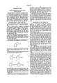
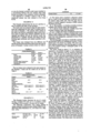
- the first stage of the production of a phenolic resole is the formation of intermediates with the formula: ##STR1## and the ratio of x/phenolic ring gives the approximate combined phenol/formaldehyde (F/P) ratio of the resin.
- the process of crosslinking and chain extension is not complete at the end of the foaming process but has progressed to such an extent that the foam has hardened and may be cut into pieces.
- the degree of cure in the absence of added crosslinking agents, is a function of temperature and, to some extent, the time of exposure to that temperature. Thus foams that are exposed to only low temperatures have a low degree of cure.
- a closed-cell foam can be made from a resole with the correct rheological properties and methods of adjusting the rheological properties of a resole during foaming by the incorporation of a suitable surfactant as described in U.S. Pat. Nos. 2,933,461; 2,845,396; 3,953,645; 4,140,842 and 4,133,931 amongst others.
- a phenolic foam useful as an insulating material requires a low thermal conductivity and clearly closed-cell foams are much preferred since they minimize heat transfer and loss by gas convection. Additionally it is desirable that the gas filling the closed-cells have as low a thermal conductivity as possible. Gases which have been found useful as blowing agents for phenolic foams include hydrocarbons and halogenated hydrocarbons (U.S. Pat. No. 2,933,461) and fluorocarbons (U.S. Pat. No. 3,389,094).
- phenolic foams are dimensional stability and low residual formaldehyde. Both these characteristics can be provided by heating the foam but as indicated above this leads to foam disruption with the conventional foams of the prior art.
- Another object of this invention is to provide a process capable of producing such aforesaid partially cured phenolic foam.
- the present invention provides a partially cured resole foam with a density of from 30 to 70 kg/m 3 and a closed-cell content of at least 85 percent, said foam being derived from a composition comprising a phenolic resole with a formaldehyde to phenol mole ratio of from 1.2:1 to 2.5:1, a blowing agent having a thermal conductivity less than 0.016 watts/m° C. and a surfactant in sufficient quantity for the resole to exhibit the Marangoni Effect during foaming; said foam characterized in that:
- the thermal conductivity of the foam after 100 days is less than 0.020 watts/m° C. and the value of ⁇ k/ ⁇ lnt is less than 0.5 ⁇ 10 -3 where ⁇ k in watts/m° C. is k 100 minus k 1 and ⁇ lnt in days is lnt 100 minus lnt 1 ; and
- the foam is characterized by its closed-cell content of at least 85% and preferably at least 90%. These levels of closed-cell content are substantially retained even after the partially cured foam has been heated to 90° C. or even higher to effect cure. This feature is unusual because, as indicated above, cure temperatures tend to rupture cell walls.
- the resole from which the foam is prepared is essentially a conventional phenol/formaldehyde resole preferably with less than 10% by weight of any ring-substituted phenolic components such as cresol, xylenol and the like.
- the F/P mole ratio of the resole is from 1.2:1 to 2.5:1 though ratios at the higher end of this range are not preferred because the excessive amount of formaldehyde prolongs the cure process. However if too small a ratio is used, complete reaction to form the foam may be difficult to achieve.
- the most preferred F/P ratios are from 1.5 to 2.2:1.
- F/P ratio means the mole ratio of chemically combined formaldehyde to phenol in the resole.
- Such ratio can be determined by carbon 13 nuclear magnetic resonance ( 13 C-NMR).
- 13 C-NMR quantitative spectra were recorded using a JEOL FX-900 spectrometer (supplied by Jeol Co., 235 Birchwood Ave., Cranford, N.J.) at ambient temperature on 50-70% weight percent solutions of resins in methanol solvent. Samples were run in a 10 mm diameter tube with 2% added tetra methyl silane as a chemical shift reference. The spectrometer was equipped with an external lithium 7 isotope lock. The analyzed spectra were the result of 1-5000 accumulations at a tip angle of 90°.
- Optimized quantitative conditions were employed with gated decoupling (proton decoupling on only during accumulation) and a pulse delay between accumulations of >5 T 1 (relaxation time). Integrated spectra were used to calculate combined F/P at an accuracy generally better than 4%.
- the density of the foam is from 30 to 70 kg/m 3 but preferred foams have densities of from 40 to 60 kg/m 3 .
- the density is obtained by cutting a core sample 3.6 cm in diameter and 2.9 cm in length; the core is weighed accurately and the density calculated.
- the viscosity of the resole measured at room temperature of 25° C. is from about 50,000 to 1,000,000 cps, with the best results obtained at a viscosity of from 80,000 to 600,000 cps and most preferably 80,000 to 300,000 cps.
- the resole can be foamed to produce a substantially closed-cell foam using foaming conditions according to the present invention that are relatively easily controlled.
- the reactivity of the resole is also very important since if it is too reactive the temperature of the foaming composition rises too high with the result that water vapor uncontrollably blows the foam and control over density and closed-cell content is lost. On the other hand, if reactivity time is too low processing times are long and uneconomical.
- a suitable test for resole reactivity is set forth hereinafter in Example 13.
- a resole is usually produced by the conventional base-catalyzed reaction using an acid subsequent to formation of the resole to neutralize the base and stabilize the resin. This of course results in the production of salt by the reaction of acid and base.
- the resole may be neutralized using sulfuric acid or carbon dioxide to give large insoluble salt particles which can easily be filtered out before the resole is used to produce a foam. It may also be possible to use unfiltered resins if no settling problems are encountered in the foaming process employed. In general, where salt particles are present, it is preferred that they be very large or very small, that is, substantially larger in diameter than that of the cell or smaller than the thickness of the cell wall.
- Resoles in which neutralization produces a soluble salt are usually not employed because of the water sensitivity such resoles often display in that the insulating properties and dimensional stability of the resulting foam can be adversely affected by ambient humidity.
- resoles containing soluble salts which are not water sensitive, such as the calcium salt of an alkyl or aromatic sulfonic acid, or have low water sensitivity can be used.
- a preferred option is the use of the so-called "dispersed-salt" resoles in which the neutralizing acid is oxalic acid and the oxalate salts formed are highly insoluble and in colloidal form with substantially no tendency to settle.
- These resins and foams made from them are described for example in U.S. Pat. Nos. 4,060,504 and 4,216,295.
- composition from which the foam is prepared comprises a surfactant material in an amount sufficient for the resole to exhibit the Marangoni Effect during foaming and thus have the capacity to produce cells with windows (the membranes between contiguous cells) that remain intact as the cell grows to its final size.
- the amount of surfactant that can be used varies somewhat with the surfactant but in general it has been observed that closed-cell foams are difficult to achieve with less than 0.5% by weight of surfactant and that over 6.0% by weight produces no advantage and may even be deleterious.
- the most useful amount of surfactant is found to be from 1 to 5% by weight. All surfactant percentages given are based on resole weight.
- the surfactant can be any one of those that have been shown effective with foamable resoles in the past.
- These include non-ionic surfactants such as polyethers, polyalcohols, particularly the condensation products of alkylene oxides with alkyl phenols, fatty acids, silanes and silicones, fatty acid esters of polyhydroxyl compounds such as sorbitan or sorbitol, polysilyl phosphonates, polydimethylsiloxane and the capped surfactants described in U.S. Pat. Nos. 4,133,931, 4,140,842 and 4,247,413, the disclosures of surfactants of which are incorporated herein by reference.
- Ionic surfactants such as alkylated quaternary ammonium derivatives may also be used.
- resole reactivity and foaming catalyst level can be expressed in terms of a reactivity number defined in Example 13 hereinafter and which can be between about 2 to about 12.
- Foaming is catalyzed by an acid and those commonly used include boric acid, sulfuric acid and sulfonic acids such as toluene and xylene sulfonic acids. Other catalytic acids however are known in the art and may be used.
- the level of catalyst used in the foaming mixture may widely vary depending on the particular resole and catalyst used. Levels between about 0.5 to about 3.0 and preferably between 1.0 to 2.0 weight percent based on the weight of the resole can be used.
- the blowing agent used must have a thermal conductivity less than 0.016 and preferably less than 0.014 watts/m° C. Typically this range includes blowing agents such as methylene dichloride, and various chlorofluorocarbons such as monofluorotrichloromethane, difluorodichloromethane, monofluorodichloromethane, difluoromonochloromethane, trifluorotrichloroethane, and tetrafluorodichloroethane. Freon 114, (1,2 dichlorotetrafluoroethane available from DuPont Company under the above trade designation) is particularly preferred.
- the level of blowing agent used in the foaming mixture is dependent on the molecular weight of the blowing agent and the density of the foam. Levels between about 5 to about 25 and preferably between 10 to 20 weight percent for Freon 114 based on the weight of the resole can be used for foams of about 30 to 70 kg/m 3 .
- the resole may comprise latent neutralizing additives to remove traces of residual curing acid and leave a neutral foam.
- latent neutralizers are described for example in U.S. Pat. Nos. 4,207,400 and 4,207,401, the disclosures and teachings of latent neutralizers of which are incorporated herein by reference.
- the foam can further comprise other additives such as anti-punking additives and particulate or fibrous fillers such as glass fibers, talc and the like, to improve the fire safety or physical characteristics of the resulting foam. It may also comprise components added after the resole formation such as lignin materials, urea, or melamine as extenders or formaldehyde scavengers. Hydrated alumina as taught in commonly owned U.S. application Ser. No. 219,165 filed Dec. 22, 1980, now U.S. Pat. No. 4,419,460 issued Dec. 6, 1983, is effective in increasing the closed-cell content and is therefore a desirable component of the foam.
- the components from which the foam is to be made comprise a resole, a surfactant, an acid catalyst and a blowing agent. These components are selected according to the principles outlined above and are mixed at a temperature and pressure calculated to ensure rapid expansion at the extrusion head.
- the mixing can be carried out in any mixer device capable of giving effective, fine (less than 10 micron) and uniform dispersion of the blowing agent in the mixture.
- a suitable mixer device for this stage of the operation is a high shear pin-type mixer with a short residence time such as an Oakes mixer.
- the preferred blowing agents are conventionally supplied under air or nitrogen pressure to the mixer.
- the foamable mixture is passed to an extrusion head. Expansion from the head is rapid and results in a stream of foaming material that is deposited on a substrate.
- the extrusion head may be in the form of a slit so as to lay down a continuous sheet of foam.
- the extrusion head is a valved pipe that reciprocates transverse to the direction of extrusion so as to lay down on a moving substrate a continuous ribbon of foam in parallel lines that coalesces as foaming proceeds.
- shaping members provide limitations to the expansion and result in the production of a uniform shaped board of the foamed resin. The shaping members may apply to the surface a suitable facing material though it may be convenient to apply such facing after hardening of the expanded foam.
- the foam is conventionally held at a constant temperature of about 60° C. This is done by passing the foamed sheet through an oven at that temperature such that on leaving the oven after about twenty minutes it has hardened enough to be cut into board pieces which are then stored at 60° C. for 18 hours. After this the board is in the partially cured state.
- the term "partially cured" as used herein means foam exposed to at least 60° C. for at least 18 hours. Though other low temperature cure conditions can be used--e.g. longer times at lower temperatures, foams of the invention have at least the degree of partial cure achieved after such 18 hours at 60° C.
- a facing may comprise cardboard, asphalt/asbestos composites, aluminum foil, plastic vapor barrier or glass fiber sheet material optionally impregnated with resin or asphalt.
- These facings may improve the surface of the foam and afford some dimensional stability. It should however be noted that cured foams have inherent three-dimensional stability up to about the temperature at which they were cured. Since the foams of the invention can be cured at temperatures in excess of those likely to be encountered in use, any facing selected need not be chosen with the problems of dimensional change in mind.
- the foam material is primarily useful as an insulating material, it is essential that it provides a good barrier to heat transfer. However it is not sufficient that the fresh foam have good thermal barrier properties; those properties must be retained for a prolonged period after installation.
- the thermal insulation characteristics of a closed-cell foam are largely determined by the rate at which heat is transferred through the foam via conduction through the cell skeleton and the gas filling the cells and via radiation through the cell structure.
- the nature of the gas is a critical element in determining conductivity as is the extent to which it is retained in the cells. It will also be appreciated that stronger and thicker cell windows will be more capable of retaining a more desirable gas composition for a longer period than weaker, thinner windows.
- the "k” after 100 days (k 100 ) referred to in this specification is the thermal conductivity one hundred days after the production of the partially cured foams of the invention.
- the partially cured foams of the invention have a k 100 of less than 0.020 watts/m° C.
- a measure of the rate of increase of thermal conductivity with time of the partially cured foams of the invention can be expressed as the value (known as k-retention) of the expression ⁇ k/ ⁇ lnt where ⁇ k is k 100 minus k 1 and ⁇ lnt is the natural log of t 100 minus the natural log of t 1 where k is the thermal conductivity of a 2.54 cm thick sample measured in watts/m° C. 100 days (k 100 ) and one day (k 1 ) after manufacture and t is elapsed time in days.
- the partially cured foams of the invention have a k-retention value of not more than 0.5 ⁇ 10 -3 .
- the k 100 value gives a good indication of the barrier properties of the foam structure but it does not necessarily adequately indicate the strength of that structure, i.e. its ability to withstand internal pressures. This indication is provided by the "burst pressure" which is the isotropic pressure at which the closed-cell content is decreased by at least 10%. Good insulating foams need to be able to withstand high pressures such as are generated during cure or even such thermal cycling as may be experienced in use. In the foams of the invention a burst pressure in excess of 1.75 kg/cm 2 is required. This, together with the k 100 value, adequately defines a new type of partially cured foam not provided by the prior art with potential for the production of a high quality, fully cured foam.
- the closed-cell content was measured by an air pycnometer using the technique described in ASTM D-2856 (Procedure C) to obtain open-cell content, the closed-cell content being 100 minus the open-cell content.
- the thermal conductivity of the foams was measured using the technique described in ASTM C-518-76 on a sample with a 2.54 cm thickness having at least 20.3 cms of width and length. The top face of the sample was at 32° C. and the bottom at 15.5° C., thereby providing a mean temperature of 24° C. for the entire sample.
- a heat flow meter thermal conductivity instrument constructed in accordance with such method and available as Rapid-K from Dynatech R/D Co., 99 Erie St., Cambridge, Mass. 02139 was used.
- the resole used in each example was dehydrated to below 3% by weight of water and bodied at 50°-60° C. for a time sufficient to provide the desired viscosity which was measured using a Brookfield viscometer Model HBT. Since viscosity variation with temperature is significant, a Brookfield thermocell was used for the resoles of the examples following hereafter which comprised a thermo container along with an SCR controller, Model HT-64, an SC4-27 spindle and an HT-2 sample container. Measurements were made at 25° C. All viscosities given were obtained by this technique.
- the burst pressure of the cells of any particular foam was determined by measuring the closed-cell content of a foam sample, then placing that sample in a pressure tube and applying a small incremental isotropic pressure. After being subjected to that pressure for five (5) minutes the closed-cell content was remeasured. The sample was then replaced in the tube and pressurized at a slightly higher isotropic pressure for five (5) minutes before being measured for closed-cell content again. This procedure was repeated at even higher pressures and a graph was plotted of closed-cell content against pressure. It was found that at a characteristic isotropic pressure for each foam the closed-cell content dropped dramatically by at least 10% and continued to drop thereafter. This pressure is called the "burst pressure".
- This Example illustrates the very high burst pressure of foams according to the invention.
- RI-5100 (Monsanto Company) a resole containing a dispersed oxalate salt as a result of the neutralization of the calcium hydroxide catalyst using oxalic acid.
- the blowing agent was supplied under air pressure and the resulting formulation was passed directly to an extrusion head in the form of a nozzle fitted with a torpedo valve to control the rate of expansion of the foamable mixture from the head.
- the temperature of the mixture at the extrusion head was between 40° and 42° C. and the pressure at the valve was kept at 3.74 to 4.42 atmospheres.
- the extrusion head was reciprocated in such a way as to lay down a continuous ribbon of the foaming mixture on a moving sheet of Kraft paper.
- the mixture was deposited in essentially parallel lines forty centimeters in length such that, as foaming occurred, the lines coalesced to form a continuous sheet.
- the foam was allowed to stand for about 10 minutes at 60° C. at which time it had hardened sufficiently to be cut using a saw into convenient pieces. Those pieces were than stored at 60° C. for 18 hours.
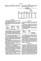
- Samples 1-A through 1-G were taken from different parts of the foam sheet produced by the above process and were tested for density, closed-cell content and thermal conductivity initially (k 1 ) and after 100 days (k 100 ). The results are set forth in Table 1.
- This Example illustrates the use of a resole having an F/P ratio of 1.6:1 to produce a foam according to the invention.
- the resole was a dispersed salt resole of the same type used in Example 1 but made at the lower F/P ratio. As before the resole was dehydrated and bodied to a viscosity of 106,000 centipoise.
- the surfactant, blowing agent and catalyst used were those described in Example 1 and the weight proportions were as follows:
- Example 2 The components were mixed, foamed and cured exactly as shown in Example 1 except that the viscosity of the resole was 106,000 cps at 25° C. and the temperature in the extrusion head 49.2° C.
- the foam When evaluated in the same manner as the foams produced in Example 1 it was found that the foam had a density of 39.4 kg/m 3 , an initial closed-cell content of 91.6%, an isotropic burst pressure of 2.46 kg/cm 2 , a k 1 of 0.0181 watts/m° C. and a k 100 of 0.187 watts/m° C. This gives a k-retention value of 0.13 ⁇ 10 -3 for the expression k 100 -k 1 /lnt 100 -lnt 1 .
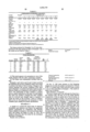
- Examples 3 to 10 illustrate the sensitivity of the process to variations in components and conditions.
- the Examples used a resole having a nominal F/P ratio of 2:1 dehydrated to different degrees to give different viscosities.
- the surfactant and the foaming catalyst were the same but the amount of surfactant and catalyst (expressed as the amount of the Ultra TX acid component) were varied.
- Additives (based on the total weight of the foamable composition) intended to enhance foam flexibility were used as indicated.
- Other differences from Example 1 are set forth in Table 2.
- Examples 1 and 2 above and 12 and 13 below set forth the materials and process conditions which were found to produce the foams of this invention. Changes in the various materials and process conditions from those used in Example 1 to produce the foams results in unsatisfactory foams as is evidenced by the results in Table 3 above. The relationship of these variables is complex and not readily understood at this time. It would appear that when one variable is changed the other variables must be reviewed and changes made as required to obtain the foams of this invention. Those of ordinary skill in the art will appreciate the interaction of these variables upon reading the present specification.
- This Example demonstrates the use of a salt-free resole to produce the foam of the invention.
- the resole used was prepared using the same proportions and components as were used to produce the resole used in Example 1.
- the calcium oxide catalyst in the resole was however neutralized using carbon dioxide in place of oxalic acid. Calcium carbonate was precipitated and filtered off and the salt-free resole was dehydrated to a suitable viscosity and mixed with the blowing agent surfactant and catalyst specified in Example 1.
- This Example further illustrates the use of a resole having a nominal F/P ratio of 2:1 to produce a foam according to the invention. All parts are by weight.
- the liquid resole contained a dispersed oxalate salt as a result of the neutralization of calcium hydroxide catalyst using oxalic acid.
- the F/P ratio was obtained by nuclear magnetic resonance (NMR) analysis described previously.
- a 2:1 weight ratio blend of diethylene glycol and Ultra TX acid which is a mixture of toluene and xylene sulfonic acids available from Witco Chemical Company under that trade designation, expressed in terms of acid component content.
- the blowing agent was held in a bomb-like container and saturated with air by bubbling air at about 15 atmospheres into it for about 4 to 6 hours. This was to promote uniform nucleation of the blowing agent on reduction of the pressure during a subsequent phase of the foaming process.
- the resole stored at about 5° C. to minimize advancement, was initially brought to room temperature (25° C.) and a laboratory test for reactivity performed thereon. This test was run at three acid levels (for Example 1, 1.5 and 1.8% acid as described in (4) above and based on resole weight) in order to measure the sensitivity of the resole reactivity to acid level.
- 150 grams of the resole and 3 grams of the DC-193 surfactant were charged to a 1 pint paper cup and mixed for one minute with a high speed mixer (720 rpm). 22.5 grams of Freon 113 blowing agent were then added and the contents mixed for an additional minute.
- the acid catalyst solution of toluene sulfonic acid and diethylene glycol was then added and mixed for an additional 30 seconds.
- reactivity number defined as the rate of temperature rise between the oven temperature and the peak temperature reached by the foaming composition, has the dimensions °C./minute and was calculated at 3.2° C./minute. This number is dependent on a number of resole characteristics--e.g. F/P ratio, water component, molecular weight, etc. and can therefore vary widely. Resoles with reactivity numbers of between about 2 to about 12 and preferably between 3 to 7 at a concentration of acid catalyst of 1.5% have been used. If the reactivity number is too high, water is added to the particular resole to reduce it whereas if the reverse is true the acid concentration is adjusted upwardly.
- the resole and surfactant were initially mixed together at about 25°-40° C. in a jacketed, paddle mixer for about 30 minutes under an absolute pressure of 5 mm. of mercury to avoid entraining air.
- the resole and surfactant, foaming catalyst and blowing agent were continuously charged to the Oakes mixer in the foregoing noted ratios through suitable flow metering devices. Turbine meters obtained from Flow Technology Inc., Sacramento, Calif. were used on the Freon and an oval gear meter obtained from Brooks Instrument Division of Emerson Electric was used on the resole-surfactant acid-catalyst streams.
- the Oakes mixer was operated at about 93 rpm and had tempered water at about 40° C. flowing through its jacket.
- the charge line carrying the resole was traced with hot water at about the same temperature.
- the blowing agent and catalyst were metered to the mixer at 25° C.
- the temperatures of the foam composition entering the mixer was about 30°-40° C. while at the discharge of the mixer it was about 45°-50° C.
- the pressure in the mixer was 6.8 atmospheres.
- the temperature increase in the high shear mixer should be minimized to limit reaction therein which tends to foul the mixer.
- the pressure in the mixer should be above the vapor pressure of the foaming agent to avoid premature foaming and with the Freon 114 of this Example, such pressure should be kept at between about 3.4-6.8 atmospheres.
- the resulting formulation passed from the mixer through a finite length of insulated transfer tube consisting of a 91 cms long by 1.27 cms diameter pipe where foaming commenced, to an extrusion head in the form of a 0.64 cm diameter nozzle just upstream of which was a bladder torpedo-control valve (Tube-O-Matic B-310208 available from Schrider Fluid Power Inc., P.O. Box 1448-71 Woodland St., Manchester, Conn. 06040).
- This air pressure controlled valve controlled the back pressure in the mixer and delivery tube and the rate of expansion of the foamable mixture issuing from the head.
- the mass flow rate of the foaming composition through the system was about 430-440 gms/minute.
- the temperature of the mixture at the nozzle was 49° C. while the pressure there was 0.68 atmospheres; the pressure at the inlet to the control valve was 3.9 atmospheres whereas the temperature at such inlet was 50.9° C.
- the extrusion head was reciprocated through about 55.9 cms in 2-4 seconds in such a way as to lay down a continuous ribbon of the foaming mixture on a sheet of natural Kraft paper 0.254 mm. thick having a weight of 205 kg/1000m 2 advancing at the rate of about 24.4 cms/min.
- the distance of the nozzle from the moving paper was kept at a minimum to minimize entrainment of air.
- the mixture was deposited in essentially parallel lines such that as foaming occurred the lines coalesced to form a continuous sheet.
- the nature of the foam deposited on the moving paper web is a function of the pressure drop across the control valve. If the pressure upstream of the valve is too high a soupy deposit is obtained which results in discernible knit lines at the juncture of the ribbon-like formations issuing from the head which eventually produce undesirable large cells along such knit lines. On the other hand if such pressure is too low shearing of the foam in the control valve and delivery tube occurs which means that the cells are ruptured and the blowing agent escapes.
- the stream issuing from the nozzle should have the consistency of a froth such that rapid expansion without significant entrapment of air occurs as the composition is deposited on the paper substrate.
- a protective Kraft paper covering was applied to the upper surface of the advancing foam sheet.
- Such covering (same characteristics as the paper substrate) passed around a fixed roller about 30.5 cms beyond the nozzle into contact with the rinsing developing foam sheet.
- the covered foam sheet was then brought into forcible compressive engagement with a succession of six immediately adjacent 3.8 cms diameter freely floating steel rolls interposed across the path of the advancing foam in order to iron out any irregularities in the foam surface and promote good wetting by the foam of the protective upper paper layer.
- the rollers serve to exert a constant pressure on the advancing foam and were vertically positioned so as to come into contact with about the upper 0.64 cms of thickness. This is important since warping of the foam product can occur in the absence of good adhesion with the top and bottom paper layers brought about by such compressive rolling contact.
- the foam sheet covered on its upper and lower faces with the Kraft paper was then passed through a hot air curing tunnel in the form of an oven obtained from Kornylak Co., 400 Heaton St., Hamilton, Ohio, described as a 25 foot Air Film Principle Foam Containment Conveyor.
- This tunnel oven consisted of a section about 7.6 m long having a succession of five pairs of perforated platens vertically spaced 15.2 cms apart, one of each pair of which was above and below the advancing foam and each of which was about 1.5 m long.
- a film of hot air controlled at 53° C. issued from the first pair of platens closest to the extrusion nozzle against the paper-covered upper and lower surfaces of the foam.
- a succession of about eight 3.8 cms diameter, immediately adjacent floating rollers were also in the oven under the first platen for contact with covered upper surface portion of the foam sheet. Air issuing from the remaining platens was kept at temperatures in the range of about 45°-55° C. The residence time of the foam in such oven was about 31 minutes at which time it had been hardened sufficiently to be cut with a saw into convenient pieces. These pieces were then stored at 60° C. for 18 hours.
- thermocouple Periodically (about once every 30 minutes) a thermocouple was inserted into the foam adjacent the extrusion nozzle and allowed to travel down the tunnel to measure the internal temperature of the foam formulation.
- the peak exotherm temperature was maintained at about 60°-65° C. and was controlled by adjusting the temperature of the hot air in the curing oven and/or the acid curing catalyst concentration in the mixture.
- Samples 5-1 through 5--5 were taken from different parts of the foam sheet produced by the foregoing process and were tested as previously described for density, closed-cell content, thermal conductivity initially (k 1 ) and after 100 days (k 100 ). The results are set forth in Table 6.
- the above data overall illustrates partially cured foam according to the invention which had a density between 30 to 70 kg/m 3 , a closed-cell content of at least 85%, a thermal conductivity after 100 days less than 0.020 watts/m° C., a k-retention value less than 0.5 ⁇ 10 -3 and an isotropic burst pressure in excess of 1.75 kg/cm 2 .
- the reason for the high k 100 and k-retention values for Samples 5-1 and 5-2 is not known.
- This example further illustrates the use of a resole having a nominal F/P ratio of 2:1 and a less than preferred viscosity to produce a foam. All parts are by weight.
- a 2:1 weight ratio blend of diethylene glycol and Ultra TX acid which is a mixture of toluene and xylene sulfonic acids available from Witco Chemical Company under that trade designation, expressed in terms of acid component content.
- the blowing agent was held in a bomb-like container and saturated with air by bubbling air at about 15 atmospheres into it for about 4 to 6 hours. This was to promote uniform nucleation of the blowing agent on reduction of the pressure during a subsequent phase of the foaming process.
- the resole stored at about 5° C. to minimize advancement, was initially brought to room temperature (25° C.) and a laboratory test for reactivity performed thereon. This test was run at three acid levels (for Example 1, 1.5 and 1.8% acid as described in (4) above and based on resole weight) in order to measure the sensitivity of the resole reactivity to acid level.
- One hundred fifty grams of the resole and 3 grams of the DC-193 surfactant were charged to a 0.57 litre (1 pint) paper cup and mixed for one minute with a high speed mixer (720 rpm). 22.5 grams of Freon 113 blowing agent were then added and the contents mixed for an additional minute.
- the acid catalyst solution of toluene sulfonic acid and diethylene glycol was then added and mixed for an additional 30 seconds.
- 100 grams of the mixed formulation was quickly charged to a cylindrical cell about 5.7 cms high and 20.3 cms diameter fitted with a thermocouple attached to a recorder.
- the capped cell was placed in an oven set at 60° C. and the peak temperature and time to reach same noted.
- the reactivity number defined as the rate of temperature rise between the oven temperature and the peak temperature reached by the foaming composition has the dimensions ° C./minute and was calculated at 8.0° C./minute. This number is dependent on a number of resole characteristics--e.g. F/P ratio, water content, molecular weight, etc. and can therefore vary widely.
- Resoles with reactivity numbers of between about 2 to about 12 and preferably between 3 to 7 at a concentration of acid catalyst of 1.5% have been used. If the reactivity number is too high, water is added to the particular resole to reduce it whereas if the reverse is true the acid concentration is adjusted upwardly.
- the resole and surfactant were initially mixed together at about 25°-40° C. in a jacketed, paddle mixer for about 30 minutes under an absolute pressure of 5 mm. of mercury to avoid entraining air.
- the resole and surfactant, foaming catalyst and blowing agent were continuously charged to the Oakes mixer in the foregoing noted ratios through suitable flow metering devices. Turbine meters obtained from Flow Technology Inc., Sacramento, Calif. were used on the Freon and an oval gear meter obtained from Brooks Instrument Division of Emerson Electric was used on the resole-surfactant acid-catalyst streams.
- the Oakes mixer was operated at about 115 rpm and had tempered water at about 40° C. flowing through its jacket.
- the charge line carrying the resole was traced with hot water at about the same temperature.
- the blowing agent and catalyst were metered to the mixer at 25° C.
- the temperatures of the foam composition entering the mixer was about 30°-40° C. while at the discharge of the mixer it was about 45°-50° C.
- the pressure in the mixer was 4.1 atmospheres.
- the temperature increase in the high shear mixer should be minimized to limit reaction therein which tends to foul the mixer.
- the pressure in the mixer should be above the vapor pressure of the foaming agent to avoid premature foaming and with the Freon 114 of this example, such pressure should be kept at between about 3.4-6.8 atmospheres.
- the resulting formulation passed from the mixer through a finite length of insulated transfer tube consisting of a 91 cms long by 1.27 cms diameter pipe where foaming commenced, to an extrusion head in the form of a 0.64 cm diameter nozzle just upstream of which was a bladder torpedo-control valve (Tube-O-Matic Valve B-310208 available from Schrider Fluid Power Inc., P.O. Box 1448-71 Woodland St., Manchester, Conn. 06040).
- This air pressure controlled valve controlled the back pressure in the mixer and delivery tube and the rate of expansion of the foamable mixture issuing from the head.
- the mass flow rate of the foaming composition through the system was about 420 gms/minute.
- the temperature of the mixture at the nozzle was about 42° C. while the pressure there was about 0.5 atmospheres; the pressure at the inlet to the control valve was about 1.5 atmospheres whereas the temperature at such inlet was about 44° C.
- the extrusion head was reciprocated through about 42 cms in 2-4 seconds in such a way as to lay down a continuous ribbon of the foaming mixture on a sheet of natural Kraft paper 0.254 mm. thick having a weight of 205 kg/1000m 2 advancing at the rate of about 20-30 cms/min.
- the distance of the nozzle from the moving paper was kept at a minimum to minimize entrainment of air.
- the mixture was deposited in essentially parallel lines such that as foaming occurred the lines coalesced to form a continuous sheet.
- the nature of the foam deposited on the moving paper web is a function of the pressure drop across the control valve. If the pressure upstream of the valve is too high a soupy deposit is obtained which results in discernible knit lines at the juncture of the ribbon-like formations issuing from the head which eventually produce undesirable large cells along such knit lines. On the other hand if such pressure is too low shearing of the foam in the control valve and delivery tube occurs which means that the cells are ruptured and the blowing agent escapes.
- the stream issuing from the nozzle should have the consistency of a froth such that rapid expansion without significant entrapment of air occurs as the composition is deposited on the paper substrate.
- a protective Kraft paper covering was applied to the upper surface of the advancing foam sheet.
- Such covering (same characteristics as the paper substrate) passed around a fixed roller about 30.5 cms beyond the nozzle into contact with the rising developing foam sheet.
- the covered foam sheet was then brought into forcible compressive engagement with a succession of six immediately adjacent 3.8 cms diameter freely floating steel rolls interposed across the path of the advancing foam in order to iron out any irregularities in the foam surface and promote good wetting by the foam of the protective upper paper layer.
- the rollers serve to exert a constant pressure on the advancing foam and were vertically positioned so as to come into contact with about the upper 0.64 cms of thickness. This is important since warping of the foam product can occur in the absence of good adhesion with the top and bottom paper layers brought about by such compressive rolling contact.
- the foam sheet covered on its upper and lower faces with the Kraft paper was then passed through a hot air curing tunnel in the form of an oven obtained from Kornylak Co., 400 Heaton St., Hamilton, Ohio, described as a 25 foot Air Film Principle Foam Containment Conveyor.
- This tunnel oven consisted of a section about 7.6 m long having a succession of five pairs of perforated platens vertically spaced 15.2 cms apart, one of each pair of which was above and below the advancing foam and each of which was about 1.5 m long.
- a film of hot air controlled at 53° C. issued from the first pair of platens closest to the extrusion nozzle against the paper-covered upper and lower surfaces of the foam.
- a succession of about eight 3.8 cms diameter, immediately adjacent floating rollers were also in the oven under the first platen for contact with covered upper surface portion of the foam sheet. Air issuing from the remaining platens was kept at temperatures in the range of about 60° C. The residence time of the foam in such oven varied from 20-50 minutes at which time it had been hardened sufficiently to be cut with a saw into convenient pieces. These pieces were then stored at 60° C. for either 18 hours, or 4 hours, or they were not heated at all.
- thermocouple Periodically (about once every 30 minutes) a thermocouple was inserted into the foam adjacent the extrusion nozzle and allowed to travel down the tunnel to measure the internal temperature of the foam formulation.
- the peak exotherm temperatures was maintained at about 60°-70° C. and was controlled by adjusting the temperature of the hot air in the curing oven and/or the acid curing catalyst concentration in the mixture.
- Runs 1 through 26 were taken at different times from the foam sheet produced by the foregoing process and were tested as previously described for density, closed-cell content and thermal conductivity after 100 days. The results are set forth in Table 7.
- This example illustrates the use of a high viscosity resole having a nominal F/P ratio of 2:1 to produce a foam according to the invention. All parts are by weight.
- the liquid resole contained a dispersed oxalate salt as a result of the neutralization of calcium hydroxide catalyst using oxalic acid.
- the F/P ratio was obtained by nuclear magnetic resonance (NMR) analysis described previously.
- a 2:1 weight ratio blend of diethylene glycol and Ultra TX acid which is a mixture of toluene and xylene sulfonic acids available from Witco Chemical Company under that trade designation, expressed in terms of acid component content.
- the blowing agent was held in a bomb-like container and saturated with air by bubbling air at about 15 atmospheres into it for about 4 to 6 hours. This was to promote uniform nucleation of the blowing agent on reduction of the pressure during a subsequent phase of the foaming process.
- the resole stored at about 5° C. to minimize advancement, was initially brought to room temperature (25° C.) and a laboratory test for reactivity performed thereon. This test was run at three acid levels (for Example 1, 1.5 and 1.8% acid as described in (4) above and based on resole weight) in order to measure the sensitivity of the resole reactivity to acid level.
- 150 grams of the resole and 3 grams of the DC-193 surfactant were charged to a 0.57 litre (1 pint) paper cup and mixed for one minute with a high speed mixer (720 rpm). 22.5 grams of Freon 113 blowing agent were then added and the contents mixed for an additional minute.
- the acid catalyst solution of toluene sulfonic acid and diethylene glycol was then added and mixed for an additional 30 seconds.
- 100 grams of the mixed formulation was quickly charged to a cylindrical cell about 5.7 cms high and 20.3 cms diameter fitted with a thermocouple attached to a recorder.
- the capped cell was placed in an oven set at 60° C. and the peak temperature and time to reach same noted.
- the reactivity number defined as the rate of temperature rise between the oven temperature and the peak temperature reached by the foaming composition has the dimensions ° C./minute and was calculated at 6.4° C./minute. This number is dependent on a number of resole characteristics--e.g. F/P ratio, water content, molecular weight, etc. and can therefore vary widely.
- Resoles with reactivity numbers of between about 12 and preferably between 3 to 7 at a concentration of acid catalyst of 1.5% have been used. If the reactivity number is too high, water is added to the particular resole to reduce it whereas if the reverse is true the acid concentration is adjusted upwardly.
- the resole and surfactant were initially mixed together at about 25°-40° C. in a jacketed, paddle mixer for about 30 minutes under an absolute pressure of 5 mm. of mercury to avoid entraining air.
- the resole and surfactant, foaming catalyst and blowing agent were continuously charged to the Oakes mixer in the foregoing noted ratios through suitable flow metering devices. Turbine meters obtained from Flow Technology Inc., Sacramento, Calif. were used on the Freon and an oval gear meter obtained from Brooks Instrument Division of Emerson Electric was used on the resole-surfactant acid-catalyst streams.
- the Oakes mixer was operated at about 130 rpm and had tempered water at about 40° C. flowing through its jacket.
- the charge line carrying the resole was traced with hot water at about the same temperature.
- the blowing agent and catalyst were metered to the mixer at 25° C.
- the temperatures of the foam composition entering the mixer was about 30°-40° C. while at the discharge of the mixer it was about 50° C.
- the pressure in the mixer was 9.0 atmospheres.
- the temperature increase in the high shear mixer should be minimized to limit reaction therein which tends to foul the mixer.
- the pressure in the mixer should be above the vapor pressure of the foaming agent to avoid premature foaming and with the Freon 114 of this example, such pressure should be kept above 5.0 atmospheres.
- the resulting formulation passed from the mixer through a finite length of insulated transfer tube consisting of 91 cms long by 1.27 cms diameter pipe where foaming commenced, to an extrusion head in the form of a 0.64 cm diameter nozzle just upstream of which was a bladder torpedo-control valve (Tube-O-Matic Valve B-310208 available from Schrider Fluid Power Inc., P.O. Box 1448-71 Woodland St., Manchester, Conn 06040).
- This air pressure controlled valve controlled the back pressure in the mixer and delivery tube and the rate of expansion of the foamable mixture issuing from the head.
- the mass flow rate of the foaming composition through the system was about 420 gms/minute.
- the temperature of the mixture at the nozzle was 57° C. while the pressure there was 1.4 atmospheres; the pressure at the inlet to the control valve was 3.5 atmospheres whereas the temperature at such inlet was 57° C.
- the extrusion head was reciprocated through about 25 cms in 3 seconds in such a way as to lay down a continuous ribbon of the foaming mixture on a sheet of cardboard advancing at the rate of about 25.4 cms/min.
- the distance of the nozzle from the moving cardboard was kept at a minimum to minimize entrainment of air.
- the mixture was deposited in essentially parallel lines such that as foaming occurred the lines coalesced to form a continuous sheet.
- the nature of the foam deposited on the moving cardboard is a function of the pressure drop across the control valve. If the pressure upstream of the valve is too high a soupy deposit is obtained which results in discernible knit lines at the juncture of the ribbon-like formations issuing from the head which eventually produce undesirable large cells along such knit lines. On the other hand if such pressure is too low shearing of the foam in the control valve and delivery tube occurs which means that the cells are ruptured and the blowing agent escapes.
- the stream issuing from the nozzle should have the consistency of a froth such that rapid expansion without significant entrapment of air occurs as the composition is deposited on the cardboard substrate.
- the foam deposited on the cardboard was placed in a hot air circulatory oven for 16 hours at 60° C. After 16 hours the closed cell content was measured.
- This example further illustrates the use of a high viscosity, resole having a nominal F/P ratio of 1.6:1, to produce a foam according to the invention. All parts are by weight.
- the liquid resole contained a soluble sodium salt as a result of the neutralization of sodium hydroxide catalyst using Ultra TX acid(5).
- the F/P ratio was obtained by nuclear magnetic resonance (NMR) analysis described previously.
- a 2:1 weight ratio blend of diethylene glycol and Ultra TX acid which is a mixture of toluene and xylene sulfonic acids available from Witco Chemical Company under that trade designation, expressed in terms of acid component content.
- Ultra TX is a mixture of toluene and xylene sulfonic acids available from Witco Chemical Co.
- the blowing agent was held in a bomb-like container and saturated with air by bubbling air at about 10 atmospheres into it for about 4 to 6 hours. This was to promote uniform nucleation of the blowing agent on reduction of the pressure during a subsequent phase of the foaming process.
- the resole stored at about 5° C. to minimize advancement, was initially brought to room temperature (25° C.) and a laboratory test for reactivity performed thereon. This test was run at three acid levels (for Example 1, 1.5 and 1.8% acid as described in (4) above and based on resole weight) in order to measure the sensitivity of the resole reactivity to acid level.
- 150 grams of the resole and 3 grams of the DC-193 surfactant were charged to a 0.57 litre (1 pint) paper cup and mixed for one minute with a high speed mixer (720 rpm). 22.5 grams of Freon 113 blowing agent were then added and the contents mixed for an additional minute.
- the acid catalyst solution of toluene sulfonic acid and diethylene glycol was then added and mixed for an additional 30 seconds.
- 100 grams of the mixed formulation was quickly charged to a cylindrical cell about 5.7 cms high and 20.3 cms diameter fitted with a thermocouple attached to a recorder.
- the capped cell was placed in an oven set at 60° C. and the peak temperature and time to reach same noted.
- the reactivity number defined as the rate of temperature rise between the oven temperature and the peak temperature reached by the foaming composition, has the dimensions ° C./minute and was calculated at 19.7° C./minute. This number is dependent on a number of resole characteristics--e.g. F/P ratio, water content, molecular weight, etc. and can therefore vary widely.
- Resoles of this type with reactivity numbers of between about 5 to about 45 and preferably between 15 to 25 at a concentration of acid catalyst of 1.5% have been used. If the reactivity number is too high, water is added to the particular resole to reduce it whereas if the reverse is true the acid concentration is adjusted upwardly.
- the resole and surfactant were initially mixed together at about 25°-40° C. in a jacketed, paddle mixer for about 30 minutes under an absolute pressure of 5 mm. of mercury to avoid entraining air.
- the resole and surfactant, foaming catalyst and blowing agent were continuously charged to the Oakes mixer in the foregoing noted ratios through suitable flow metering devices. Turbine meters obtained from Flow Technology Inc., Sacramento, Calif. were used on the Freon and an oval gear meter obtained from Brooks Instrument Division of Emerson Electric was used on the resole-surfactant acid-catalyst streams.
- the Oakes mixer was operated at about 180 rpm and had tempered water at about 40° C. flowing through its jacket.
- the charge line carrying the resole was traced with hot water at about the same temperature.
- the blowing agent and catalyst were metered to the mixer at 25° C.
- the temperatures of the foam composition entering the mixer was about 30°-40° C. while at the discharge of the mixer it was about 52° C.
- the pressure in the mixer was 8 atmospheres.
- the temperature increase in the high shear mixer should be minimized to limit reaction therein which tends to foul the mixer.
- the pressure in the mixer should be above the vapor pressure of the foaming agent to avoid premature foaming and with the Freon 114 of this example, such pressure should be kept at between about 6-10 atmospheres.
- the resulting formulation passed from the mixer through a finite length of insulated transfer tube consisting of a 91 cms long by 1.27 cms diameter pipe where foaming commenced, to an extrusion head in the form of a 0.64 cm diameter nozzle just upstream of which was a bladder torpedo-control valve (Tube-O-Matic Valve B-310208 available from Schrider Fluid Power Inc., P.O. Box 1448-71 Woodland St., Manchester, Conn 06040).
- This air pressure controlled valve controlled the back pressure in the mixer and delivery tube and the rate of expansion of the foamable mixture issuing from the head.
- the mass flow rate of the foaming composition through the system was about 720 gms/minute.
- the temperature of the mixture at the nozzle was 53° C. while the pressure there was about 0.5 atmospheres; the pressure at the inlet to the control valve was 3.4 atmospheres whereas the temperature at such inlet was about 54° C.
- the extrusion head was reciprocated through about 110 cms in 4-6 seconds in such a way as to lay down a continuous ribbon of the foaming mixture on a sheet of natural Kraft paper 0.254 mm. thick having a weight of 205 kg/1000m 2 advancing at the rate of about 29 cms/min.
- the distance of the nozzle from the moving paper was kept at a minimum to minimize entrainment of air.
- the mixture was deposited in essentially parallel lines such that as foaming occurred the lines coalesced to form a continuous sheet.
- the nature of the foam deposited on the moving paper web is a function of the pressure drop across the control valve. If the pressure upstream of the valve is too high a soupy deposit is obtained which results in discernible knit lines at the juncture of the ribbon-like formations issuing from the head which eventually produce undesirable large cells along such knit lines. On the other hand if such pressure is too low shearing of the foam in the control valve and delivery tube occurs which means that the cells are ruptured and the blowing agent escapes.
- the stream issuing from the nozzle should have the consistency of a froth such that rapid expansion without significant entrapment of air occurs as the composition is deposited on the paper substrate.
- a protective Kraft paper covering was applied to the upper surface of the advancing foam sheet.
- Such covering (same characteristics as the paper substrate) passed around a fixed roller about 30.5 cms beyond the nozzle into contact with the rising developing foam sheet.
- the covered foam sheet was then brought into forcible compressive engagement with a succession of six immediately adjacent 3.8 cms diameter freely floating steel rolls interposed across the path of the advancing foam in order to iron out any irregularities in the foam surface and promote good wetting by the foam of the protective upper paper layer.
- the rollers serve to exert a constant pressure on the advancing foam and were vertically positioned so as to come into contact with about the upper 0.64 cms of thickness. This is important since warping of the foam product can occur in the absence of good adhesion with the top and bottom paper layers brought about by such compressive rolling contact.
- the foam sheet covered on its upper and lower faces with the Kraft paper was then passed through a hot air curing tunnel in the form of an oven obtained from Kornylak Co., 400 Heaton St., Hamilton, Ohio, described as a 25 foot Air Film Principle Foam Containment Conveyor.
- This tunnel oven consisted of a section about 7.6 m long having a succession of five pairs of perforated platens vertically spaced 15.2 cms apart, one of each pair of which was above and below the advancing foam and each of which was about 1.5 m long.
- a film of hot air controlled at 53° C. issued from the first pair of platens closest to the extrusion nozzle against the paper-covered upper and lower surfaces of the foam.
- a succession of about eight 3.8 cms diameter, immediately adjacent floating rollers were also in the oven under the first platen for contact with covered upper surface portion of the foam sheet. Air issuing from the remaining platens was kept at temperatures in the range of about 55°-65° C. The residence time of the foam in such oven was about 21 minutes at which time it had been hardened sufficiently to be cut with a saw into convenient pieces. These pieces were then stored at 60° C. for 18 hours.
- thermocouple Periodically (about once every 30 minutes) a thermocouple was inserted into the foam adjacent the extrusion nozzle and allowed to travel down the tunnel to measure the internal temperature of the foam formulation.
- the peak exotherm temperature was maintained at about 65°-70° C. and was controlled by adjusting the temperature of the hot air in the curing oven and/or the acid curing catalyst concentration in the mixture.
- Samples 16-1 through 16-3 were taken from different parts of the foam sheet produced by the foregoing process and were tested as previously described for density, closed-cell content, thermal conductivity initially (k) and after 100 days (k 100 ). The results are set forth in Table 8.
- the above data overall illustrates partially cured foam according to the invention which had a density between 30 to 70 kg/m 3 , a closed-cell content of at least 85%, a thermal conductivity after 100 days less than 0.020 watts/m° C., a k-retention value less than 0.5 ⁇ 10 -3 and an isotropic burst pressure in excess of 1.75 kg/cm 2 . Even the k retention value aged at 140° F. is less than 0.5 ⁇ 10 -3 .
Abstract
Description
______________________________________
Resole (1)    F/P ratio 1.89:1
                            96      parts
              Viscosity at 25° C.
                            100,000 cps
Blowing Agent Freon 114 (2)     16.5  parts
Surfactant    DC-193    (3)     4     parts
Foaming Catalyst        (4)     2.24  parts
All Parts Being by Weight
______________________________________
                                  TABLE 1
__________________________________________________________________________
FOAM PROPERTIES
                     Thermal
                     Conduct.
                     (watt/m °C.)
Sample     Initial
                Burst     k.sub.100
 Invention)(A-G
       (kg/m.sup.3)Density
            cell (%)closed-
                 (kg/cm.sup.2)Pressure
                      (Initial)k.sub.1
                           (-days)100
                                ##STR3##
__________________________________________________________________________
1-A   47.9 94.2 2.81+
                     .0161
                          .0164
                               .065
1-B   47.9 90.7 2.81+
                     .0161
                          .0164
                               .065
1-C   47.9 92.4 2.81+
                     .0161
                          .0164
                               .065
1-D   47.9 94.6 2.81+
                     .0161
                          .0164
                               .065
1-E   47.9 95.1 2.81+
                     .0161
                          .0164
                               .065
1-F   47.9 91.1 2.81+
                     .0161
                          .0164
                               .065
1-G   48.2 95.0 2.74 .0161
                          .0164
                               .065
__________________________________________________________________________
 *Δk is k.sub.100 -k.sub.1 and Δlnt is lnt.sub.100 -lnt.sub.1.
______________________________________
Resole        96     parts
Blowing Agent 16.5   parts
Surfactant    4      parts
Foaming Catalyst
              1.54   parts   (expressed in terms
                             of the acid compon-
                             ent of the catalyst)
______________________________________
                                  TABLE 2
__________________________________________________________________________
COMPARISON OF PROCESS VARIABLES
Variable
        Example
             Examples 3-10
Condition
        1    3   4   5   6   7   8   9   10
__________________________________________________________________________
Viscosity
        100,000
             190,000
                 100,000
                     86,000
                         93,100
                             23,000
                                 74,000
                                     74,000
                                         30,000
of Resin
(cps at 25° C.)
+pph    4    4   2   4   4   4   4   4   4
Surfactant
Blowing Freon
             Freon
                 Freon*
                     Freon
                         Freon*
                             Freon*
                                 Freon*
                                     Freon*
                                         Freon
Agent   114  114 11  114 11  11  11  11  114
% Blowing
        13.7 19.4
                 12.9
                     16.5
                         11.8
                             8.2 7.5 11  13
Agent
+pph Acid
        2.24 2.01
                 1.40
                     2.02
                         1.80
                             1.90
                                 2.06
                                     2.00
                                         2.07
Temperature
        40-42
             52.5
                 54.1
                     48.8
                         --  --  --  --  65.5
at Extrusion
(°C.)
Temperature In
        38-40
             51.5
                 53.1
                     47.0
                         39.0
                             42.0
                                 38.0
                                     38.0
                                         --
Mixer (°C.)
Additive
        None None
                 None
                     None
                         8%  8%  4%  4%  None
                         TBEP.sup.1
                             EVC.sup.2
                                 TBEP.sup.1
                                     TBEP.sup.1
__________________________________________________________________________
 *A fluorocarbon (trichloromonofluoromethane) available from DuPont under
 that designation.
 + Based on 100 parts of resin
  .sup.1 Tributoxy ethyl phosphate from Monsanto Industrial Chemical Co.
 .sup.2 Ethylene vinyl chloride latex as Airflex 4514 from Air Products an
 Chemicals Inc.
                                  TABLE 3
__________________________________________________________________________
FOAM PROPERTIES
                      Thermal
          Closed-
                 Burst
                      Conductivity
 Example
      (kg/m.sup.3)Density
           Content (%)Cell
                  (kg/cm.sup.2)Pressure
                       k.sub.1k.sub.100(watts/m °C.)
                               ##STR4##
__________________________________________________________________________
3    30.0 (91.0) 1.41 .0132
                          .0246
                              2.48
4    41.7 77.5   1.34 .0158
                          .0331
                              3.76
5    38.5 (90.5) 1.90 (1)
                      .0167
                          .0331
                              3.56
6    52.9 (88.0) 0.84 .0173
                          .0317
                              3.13
7    49.7 71.0   0.49 .0158
                          .0331
                              3.76
8    70.5 60.0   0.98 .0317
                          .0317
                              -- (2)
9    51.3 60.0   0.14 .0317
                          .0317
                              -- (2)
10   46.0 94.3   --   .0167
                          .0331
                              3.56
__________________________________________________________________________
______________________________________
Density             35.2 kg/m.sup.3
Closed-Cell Content 97%
Thermal Conductivity
                    0.0132 watts/m° C.
(as received)
Thermal Conductivity
                    0.0176 watts/m° C.
(after 100 days)
Δk/Δ1nt 0.96 × 10.sup.-3
______________________________________
              TABLE 4
______________________________________
FOAM PRODUCTION
                  Sample 1
                          Sample 2
______________________________________
Resole              96 parts  96 parts
Viscosity (cps)     75,200    82,400
Blowing Agent       17.2 parts
                              17.2 parts
Surfactant          4.0 parts 4.0 parts
Catalyst            2.01 parts
                              1.98 parts
Extrusion Head Temperature
                    46° C.
                              --
Extrusion Head Pressure
                    3.53      4.22
(atmosphere)
______________________________________
              TABLE 5
______________________________________
FOAM PRODUCTION
Property     Sample 1      Sample 2
______________________________________
Density
kg/m.sup.3   39.57         39.73
Closed-Cell
Content      96.1%         97.7%
Thermal Conductivity
initial (k.sub.1)
             0.0153 watts/m° C.
                           0.0153 watts/m° C.
after 100 days
             0.0167 watts/m° C.
                           0.0162 watts/m° C.
(k.sub.100)
Burst Pressure
             1.90          2.18
kg/cm.sup.2
Δk/Δ1nt
             0.30 × 10.sup.-3
                           0.20 × 10.sup.-3
(from k.sub.1 to k.sub.100)
______________________________________
______________________________________
Resole      F/P ratio 1.93:1
                          (1)    96    parts
            Viscosity at 25° C.
                          263,000
                                 cps
Blowing Agent
            Freon 114     (2)    15    parts
Surfactant  DC-193        (3)    4     parts
Foaming Catalyst          (4)    2.2   parts
______________________________________
                                  TABLE 6
__________________________________________________________________________
EXAMPLE 13 - FOAM PROPERTIES
             Initial       Thermal Conductivity
    Time.sup.(4)
        Density
             Closed Cell
                   Burst Pressure
                           k.sub.1
                                  k.sub.100
                                         k-reten-
Sample
    (hour)
        (kg/m.sup.3)
             (%)   (kg/cm.sup.2)
                           (watts/m °C.)
                                  (watts/m °C.)
                                         tion* × 10.sup.3
__________________________________________________________________________
5-1.sup.(1)
    1344
        45.9 95.5  --      0.0160 0.0240 1.72
5-2.sup.(1)
    1402
        46.7 97.0  3.5     0.0164 0.0260 1.88
5-3.sup.(2)
    1401
        47.7 98.4  3.0     0.0160 0.0171 0.19
5-4.sup.(3)
    1355
        46.5 98.4  3.5     0.0163 0.0173 0.24
5-5.sup.(1)
    1459
        47.1 97.6  3.2     0.0160 0.0168 0.19
__________________________________________________________________________
 *k.sub.100 - k.sub.1 /ln 100 - 1  i.e. Δk/Δln (time) for time
 (t) = 1 to 100
 .sup.(1) Sample taken at outlet of Kornylak oven and immediately precured
 @ 60° C. for 18 hours.
 .sup.(2) Sample taken at outlet of Kornylak oven, held overnight at
 insideambient room temperature conditions, then precured @ 60° C.
 for 18 hours the next day.
 .sup.(3) As for (1) except that additional cure @ 90° C. for 2
 hours before testing begun.
 .sup.(4) Of the day when run occurred when sample was taken.
______________________________________
Resole      F/P ratio 2.07:1
                          (1)    96     parts
            Viscosity at 25° C.
                                 77,000 cps
Blowing Agent
            Freon 114     (2)    13     parts
Surfactant  DC-193        (3)    4      parts
Foaming Catalyst          (4)    1.34-1.64
                                        parts
______________________________________
              TABLE 7
______________________________________
                               k Retention Value
Sample
      Density(Kg/m.sup.3)
                   Closed Cell %
                               δk/δ 1nt
______________________________________
14-1  49.5         67.5
14-2  50.4         67.4
14-3  57.5         80.7
14-4  51.5         88.0
14-5  52.7         86.4        1.56 × 10.sup.-3
14-6  56.0         57.1
14-7  51.9         72.1
14-8  54.1         88.8
14-9  54.6         79.3
14-10 54.1         86.9
14-11 46.7         67.7
14-12 46.6         8.2
14-13 53.8         89.6        1.37 × 10.sup.-3
14-14 50.4         93.7        0.66 × 10.sup.-3
14-15 52.3         91.8
14-16 53.8         91.6
14-17 47.5         3.7
14-18 47.7         15.6
14-19 48.8         96.0        0.66 × 10.sup.-3
14-20 43.2         18.0
14-21 45.4         39.9
14-22 45.6         42.7
14-23 41.6         13.6
14-24 33.6         2.7
14-25 37.9         15.6
14-26 42.9         92.2        0.75 × 10.sup.-3
______________________________________
______________________________________
Resole      F/P ratio 1.93:1
                          (1)    96    parts
            Viscosity at 25° C.
                                 472,000
                                       cps
Blowing Agent
            Freon 114     (2)    13.8  parts
Surfactant  DC-193        (3)    4     parts
Foaming Catalyst          (4)    1.3   parts
______________________________________
______________________________________
            Density
                   Closed Cell Content
______________________________________
Sample 15-1   47.5     89.9%
15-2          40.3     87.2%
______________________________________
______________________________________
Resole      F/P ratio 1.6:1
                         (1)     96    parts
            Viscosity at 25° C.
                                 230,000
                                       cps
Blowing Agent
            Freon 114    (2)     13.6  parts
Surfactant  DC-193       (3)     4     parts
Foaming Catalyst         (4)     2.1   parts
______________________________________
                                  TABLE 8
__________________________________________________________________________
EXAMPLE 16 - FOAM PROPERTIES
__________________________________________________________________________
                              Thermal Conductivity
                Initial       (3) Estimate
      Time (2)
           Density
                Closed Cell
                      Burst Pressure
                              k.sub.1
                                     k.sub.100
                                            k-reten-
Sample (1)
      (hour)
           (kg/m.sup.3)
                (%)   (kg/cm.sup.2)
                              (watts/m °C.)
                                     (watts/m °C.)
                                            tion* × 10.sup.3
__________________________________________________________________________
16-1  1407 41.3 97.4  --      .0163  .0169  0.13
16-2  1437 42.05
                96.5  2.9     .0160  .0166  0.13
16-3  1534 41.7 98.3  2.9     .0157  .0163  0.13
__________________________________________________________________________
*k.sub.100 - k.sub.1 /ln 100 - 1n 1 - i.e. Δk/Δln for time
(t) = 1 to 100
(1) Sample taken at outlet of Kornylak oven and immediately pre-cured @
60° C. for 18 hours
before testing begun.
(2) Of the day when run occurred when sample was taken.
(3) These samples were aged at 140° F. instead of 73° F.
Because of increases in diffusion,
the aging rate at 140° F. is known to be 3 times the rate at
73° F. The data @ 140° F.
follows:
   k.sub.1
      k.sub.100 @ 140° F.
              k.sub.100 Estimate @ 73° F.
16-1
   0.0163
      0.0180  0.0169
16-2
   0.0160
      0.0177  0.0166
16-3
   0.0157
      0.0176  0.0163
Claims (11)
Priority Applications (1)
| Application Number | Priority Date | Filing Date | Title |
|---|---|---|---|
| US07/176,463 US4900759A (en) | 1981-05-20 | 1988-04-01 | Phenolic foams |
Applications Claiming Priority (4)
| Application Number | Priority Date | Filing Date | Title |
|---|---|---|---|
| US26550881A | 1981-05-20 | 1981-05-20 | |
| US36592282A | 1982-04-08 | 1982-04-08 | |
| US92551586A | 1986-10-28 | 1986-10-28 | |
| US07/176,463 US4900759A (en) | 1981-05-20 | 1988-04-01 | Phenolic foams |
Related Parent Applications (1)
| Application Number | Title | Priority Date | Filing Date |
|---|---|---|---|
| US92551586A Continuation | 1981-05-20 | 1986-10-28 |
Publications (1)
| Publication Number | Publication Date |
|---|---|
| US4900759A true US4900759A (en) | 1990-02-13 |
Family
ID=27497195
Family Applications (1)
| Application Number | Title | Priority Date | Filing Date |
|---|---|---|---|
| US07/176,463 Expired - Lifetime US4900759A (en) | 1981-05-20 | 1988-04-01 | Phenolic foams |
Country Status (1)
| Country | Link |
|---|---|
| US (1) | US4900759A (en) |
Cited By (10)
| Publication number | Priority date | Publication date | Assignee | Title |
|---|---|---|---|---|
| US5407963A (en) * | 1994-06-09 | 1995-04-18 | Willson; Jennifer | Non-CFC foam produced using blended surfactants |
| WO1997012922A1 (en) * | 1995-10-04 | 1997-04-10 | Owens Corning | Process for producing shaped phenolic foams |
| US6013689A (en) * | 1997-05-02 | 2000-01-11 | Jiffy Foam, Inc. | Method for making a closed-cell phenolic resin foam, foamable composition, and closed-cell phenolic resin foam |
| US6492432B1 (en) | 1999-11-09 | 2002-12-10 | American Foam Technologies, Inc. | Novolac-epoxy resin foam, foamable composition for making novolac-epoxy resin foam and method of making novolac-epoxy resin foam |
| EP1979147A1 (en) | 2006-01-30 | 2008-10-15 | Kingsplan Holdings (IRL) Limited | A phenolic foam board |
| US20090270005A1 (en) * | 2005-09-08 | 2009-10-29 | Kingspan Holding (Irl) Limited | Expandable Resol Type Phenolic Resin Molding Material and Phenolic Resin Foam |
| US20110263731A1 (en) * | 2008-11-07 | 2011-10-27 | Asahi Kasei Construction Materials Corporation | Expandable phenolic resin composition, phenolic resin foam, and method for producing the phenolic resin foam |
| US20130011655A1 (en) * | 2010-03-26 | 2013-01-10 | Asahi Kasei Construction Materials Corporation | Phenolic resin foam laminated sheet and method for manufacturing the same |
| US20140303269A1 (en) * | 2011-11-18 | 2014-10-09 | Momentive Specialty Chemicals Inc. | Foam material on the basis of phenolic resin |
| US20180362435A1 (en) * | 2017-06-14 | 2018-12-20 | Chevron Phillips Chemical Company Lp | High porosity aromatic resins as promoters in acrylate production from coupling reactions of olefins and carbon dioxide |
Citations (14)
| Publication number | Priority date | Publication date | Assignee | Title |
|---|---|---|---|---|
| US3389094A (en) * | 1963-10-10 | 1968-06-18 | Union Carbide Corp | Foaming phenol-formaldehyde resins with fluorocarbons |
| US4036793A (en) * | 1973-04-26 | 1977-07-19 | The Celotex Corporation | Phenolic polymer, related products and processes thereof |
| US4133931A (en) * | 1976-05-19 | 1979-01-09 | The Celotex Corporation | Closed cell phenolic foam |
| US4140842A (en) * | 1977-09-29 | 1979-02-20 | The Celotex Corporation | Phenolic foam and surfactant useful therein |
| US4176216A (en) * | 1977-07-28 | 1979-11-27 | Union Carbide Corporation | Cellular products derived from phenol/formaldehyde resoles |
| US4207400A (en) * | 1977-11-16 | 1980-06-10 | Monsanto Company | Foamable resole resin composition |
| US4207401A (en) * | 1978-06-05 | 1980-06-10 | Monsanto Company | Foamable resole resin composition |
| US4216295A (en) * | 1976-12-20 | 1980-08-05 | Monsanto Company | Foamable resole resin composition |
| GB1580565A (en) * | 1976-06-07 | 1980-12-03 | Gusmer Frederick Emil | Cured phenol-aldehyde resin foam |
| US4247413A (en) * | 1979-12-03 | 1981-01-27 | The Celotex Corporation | Phenolic foam and surfactant useful therein |
| BE890667A (en) * | 1980-10-09 | 1982-02-01 | Koppers Co Inc | WERKWIJZE VOOR DE BEREIDING VAN EEN FENOLSCHUIM ONDER TOEPASSING VAN DRUK EN GEVORMDE VOORWERPEN UIT FENOLSCHUIM VERKREGEN MET DE WERKWIJZE |
| US4444912A (en) * | 1981-07-10 | 1984-04-24 | Koppers Company, Inc. | Phenolic foam and composition and method for preparing the same |
| US4478958A (en) * | 1981-07-10 | 1984-10-23 | Kopper Company, Inc. | Method for preparing phenolic foams using anhydrous aryl sulfonic acid catalysts |
| US4539338A (en) * | 1982-07-09 | 1985-09-03 | Koppers Company, Inc. | Phenol formaldehyde resoles for making phenolic foam |
-
1988
- 1988-04-01 US US07/176,463 patent/US4900759A/en not_active Expired - Lifetime
Patent Citations (15)
| Publication number | Priority date | Publication date | Assignee | Title |
|---|---|---|---|---|
| US3389094A (en) * | 1963-10-10 | 1968-06-18 | Union Carbide Corp | Foaming phenol-formaldehyde resins with fluorocarbons |
| US4036793A (en) * | 1973-04-26 | 1977-07-19 | The Celotex Corporation | Phenolic polymer, related products and processes thereof |
| US4133931A (en) * | 1976-05-19 | 1979-01-09 | The Celotex Corporation | Closed cell phenolic foam |
| US4303758A (en) * | 1976-06-07 | 1981-12-01 | Gusmer Frederick E | Method of preparing closed cell phenol-aldehyde foam and the closed cell foam thus prepared |
| GB1580565A (en) * | 1976-06-07 | 1980-12-03 | Gusmer Frederick Emil | Cured phenol-aldehyde resin foam |
| US4216295A (en) * | 1976-12-20 | 1980-08-05 | Monsanto Company | Foamable resole resin composition |
| US4176216A (en) * | 1977-07-28 | 1979-11-27 | Union Carbide Corporation | Cellular products derived from phenol/formaldehyde resoles |
| US4140842A (en) * | 1977-09-29 | 1979-02-20 | The Celotex Corporation | Phenolic foam and surfactant useful therein |
| US4207400A (en) * | 1977-11-16 | 1980-06-10 | Monsanto Company | Foamable resole resin composition |
| US4207401A (en) * | 1978-06-05 | 1980-06-10 | Monsanto Company | Foamable resole resin composition |
| US4247413A (en) * | 1979-12-03 | 1981-01-27 | The Celotex Corporation | Phenolic foam and surfactant useful therein |
| BE890667A (en) * | 1980-10-09 | 1982-02-01 | Koppers Co Inc | WERKWIJZE VOOR DE BEREIDING VAN EEN FENOLSCHUIM ONDER TOEPASSING VAN DRUK EN GEVORMDE VOORWERPEN UIT FENOLSCHUIM VERKREGEN MET DE WERKWIJZE |
| US4444912A (en) * | 1981-07-10 | 1984-04-24 | Koppers Company, Inc. | Phenolic foam and composition and method for preparing the same |
| US4478958A (en) * | 1981-07-10 | 1984-10-23 | Kopper Company, Inc. | Method for preparing phenolic foams using anhydrous aryl sulfonic acid catalysts |
| US4539338A (en) * | 1982-07-09 | 1985-09-03 | Koppers Company, Inc. | Phenol formaldehyde resoles for making phenolic foam |
Cited By (19)
| Publication number | Priority date | Publication date | Assignee | Title |
|---|---|---|---|---|
| US5407963A (en) * | 1994-06-09 | 1995-04-18 | Willson; Jennifer | Non-CFC foam produced using blended surfactants |
| WO1997012922A1 (en) * | 1995-10-04 | 1997-04-10 | Owens Corning | Process for producing shaped phenolic foams |
| US5973018A (en) * | 1995-10-04 | 1999-10-26 | Owens-Corning Fiberglas Technology, Inc. | Process for producing shaped phenolic foams |
| US6013689A (en) * | 1997-05-02 | 2000-01-11 | Jiffy Foam, Inc. | Method for making a closed-cell phenolic resin foam, foamable composition, and closed-cell phenolic resin foam |
| US6492432B1 (en) | 1999-11-09 | 2002-12-10 | American Foam Technologies, Inc. | Novolac-epoxy resin foam, foamable composition for making novolac-epoxy resin foam and method of making novolac-epoxy resin foam |
| US6610754B1 (en) | 1999-11-09 | 2003-08-26 | American Foam Technologies, Inc. | Novolac-epoxy resin foam, foamable composition for making novolac-epoxy resin foam and method of making novolac-epoxy resin foam |
| US20030216487A1 (en) * | 1999-11-09 | 2003-11-20 | Rader Samuel L. | Novolac-epoxy resin foam, foamable composition for making novolac-epoxy resin foam and method of making novolac-epoxy resin foam |
| US6727293B2 (en) | 1999-11-09 | 2004-04-27 | American Foam Technologies, Inc. | Novolac-epoxy resin foam, foamable composition for making novolac-epoxy resin foam and method of making novolac-epoxy resin foam |
| US20090270005A1 (en) * | 2005-09-08 | 2009-10-29 | Kingspan Holding (Irl) Limited | Expandable Resol Type Phenolic Resin Molding Material and Phenolic Resin Foam |
| EP1979147A1 (en) | 2006-01-30 | 2008-10-15 | Kingsplan Holdings (IRL) Limited | A phenolic foam board |
| US20100178458A1 (en) * | 2006-01-30 | 2010-07-15 | Vincent Coppock | Phenolic Foam Board |
| US20110263731A1 (en) * | 2008-11-07 | 2011-10-27 | Asahi Kasei Construction Materials Corporation | Expandable phenolic resin composition, phenolic resin foam, and method for producing the phenolic resin foam |
| US9120904B2 (en) * | 2008-11-07 | 2015-09-01 | Asahi Kasei Contruction Materials Corporation | Expandable phenolic resin composition, phenolic resin foam, and method for producing the phenolic resin foam |
| US20130011655A1 (en) * | 2010-03-26 | 2013-01-10 | Asahi Kasei Construction Materials Corporation | Phenolic resin foam laminated sheet and method for manufacturing the same |
| US9975311B2 (en) * | 2010-03-26 | 2018-05-22 | Asahi Kasei Construction Materials Corporation | Phenolic resin foam laminated sheet and method for manufacturing the same |
| US20140303269A1 (en) * | 2011-11-18 | 2014-10-09 | Momentive Specialty Chemicals Inc. | Foam material on the basis of phenolic resin |
| US9464152B2 (en) * | 2011-11-18 | 2016-10-11 | Hexion Inc. | Foam material on the basis of phenolic resin |
| US20180362435A1 (en) * | 2017-06-14 | 2018-12-20 | Chevron Phillips Chemical Company Lp | High porosity aromatic resins as promoters in acrylate production from coupling reactions of olefins and carbon dioxide |
| US20210340092A1 (en) * | 2017-06-14 | 2021-11-04 | Chevron Phillips Chemical Company Lp | High porosity aromatic resins as promoters in acrylate production from coupling reactions of olefins and carbon dioxide |
Similar Documents
| Publication | Publication Date | Title |
|---|---|---|
| US5234969A (en) | Cured phenolic foams | |
| US4900759A (en) | Phenolic foams | |
| US4444912A (en) | Phenolic foam and composition and method for preparing the same | |
| US4478958A (en) | Method for preparing phenolic foams using anhydrous aryl sulfonic acid catalysts | |
| KR20150081449A (en) | Phenolic resin foam and method for producing same | |
| US4539338A (en) | Phenol formaldehyde resoles for making phenolic foam | |
| JPS6013819B2 (en) | Method for producing phenolic foam using pressure | |
| EP0432355A2 (en) | Improved closed cell phenolic foam containing alkyl glucosides | |
| EP0066968B1 (en) | Partially cured phenolic resin foams | |
| EP0066967B1 (en) | Cured phenolic foams | |
| US4202945A (en) | Phenolic foam materials and method of making same | |
| PT90957B (en) | METHOD FOR PREPARING HARD FOAM OF ESSENTIALLY CLOSED CELL STRUCTURE | |
| GB2125055A (en) | Phenolic foams | |
| CA1281701C (en) | Modified phenolic foam catalysts and method | |
| JPS6362542B2 (en) | ||
| US4883824A (en) | Modified phenolic foam catalysts and method | |
| JPS6362541B2 (en) | ||
| US6586484B1 (en) | Phenol foam | |
| JPS60130628A (en) | Production of resol phenolic resin foam | |
| IE55613B1 (en) | Improvements in or relating to phenolic foams | |
| IE55614B1 (en) | Improvements in or relating to phenolic foams | |
| Broennum | CFC-free polyurethane pipe insulation foams for use in district heating systems | |
| IE55615B1 (en) | Improvements in or relating to phenolic foams | |
| JPH0575780B2 (en) |
Legal Events
| Date | Code | Title | Description |
|---|---|---|---|
| AS | Assignment |
Owner name: MONSANTO COMPANY, MISSOURI Free format text: ASSIGNMENT OF ASSIGNORS INTEREST.;ASSIGNORS:CLARK, ROBERT C.;KAVANAGH, DEAN L.;REEL/FRAME:005132/0648;SIGNING DATES FROM 19890713 TO 19890719 |
|
| STCF | Information on status: patent grant |
Free format text: PATENTED CASE |
|
| CC | Certificate of correction | ||
| FEPP | Fee payment procedure |
Free format text: PAYOR NUMBER ASSIGNED (ORIGINAL EVENT CODE: ASPN); ENTITY STATUS OF PATENT OWNER: LARGE ENTITY |
|
| FPAY | Fee payment |
Year of fee payment: 4 |
|
| FEPP | Fee payment procedure |
Free format text: PAYER NUMBER DE-ASSIGNED (ORIGINAL EVENT CODE: RMPN); ENTITY STATUS OF PATENT OWNER: LARGE ENTITY |
|
| FEPP | Fee payment procedure |
Free format text: PAYOR NUMBER ASSIGNED (ORIGINAL EVENT CODE: ASPN); ENTITY STATUS OF PATENT OWNER: LARGE ENTITY |
|
| FPAY | Fee payment |
Year of fee payment: 8 |
|
| AS | Assignment |
Owner name: SOLUTIA INC., MISSOURI Free format text: ASSIGNMENT OF ASSIGNORS INTEREST;ASSIGNOR:MONSANTO COMPANY;REEL/FRAME:008820/0846 Effective date: 19970824 |
|
| FPAY | Fee payment |
Year of fee payment: 12 |
|
| AS | Assignment |
Owner name: UCB CHIP INC., DELAWARE Free format text: ASSIGNMENT OF ASSIGNORS INTEREST;ASSIGNOR:SOLUTIA INC.;REEL/FRAME:014033/0647 Effective date: 20030131 |
|
| AS | Assignment |
Owner name: ABLECO FINANCE LLC, AS COLLATERAL AGENT, NEW YORK Free format text: ASSIGNMENT FOR SECURITY;ASSIGNOR:SOLUTIA INC.;REEL/FRAME:014043/0021 Effective date: 20031008 Owner name: ABLECO FINANCE LLC, AS COLLATERAL AGENT,NEW YORK Free format text: ASSIGNMENT FOR SECURITY;ASSIGNOR:SOLUTIA INC.;REEL/FRAME:014043/0021 Effective date: 20031008 |
|
| AS | Assignment |
Owner name: ABLECO FINANCE LLC, NEW YORK Free format text: SHORT-FORM JUNIOR PATENT SECURITY AGREEMENT;ASSIGNOR:SOLUTIA INC.;REEL/FRAME:014683/0683 Effective date: 20031008 Owner name: ABLECO FINANCE LLC,NEW YORK Free format text: SHORT-FORM JUNIOR PATENT SECURITY AGREEMENT;ASSIGNOR:SOLUTIA INC.;REEL/FRAME:014683/0683 Effective date: 20031008 |
|
| AS | Assignment |
Owner name: SURF CHIP, INC., DELAWARE Free format text: CHANGE OF NAME;ASSIGNOR:UCB CHIP, INC.;REEL/FRAME:015442/0636 Effective date: 20041001 |
|
| AS | Assignment |
Owner name: SURF CHIP, INC., DELAWARE Free format text: SECURITY AGREEMENT;ASSIGNOR:ABLECO FINANCE LLC, AS COLLATERAL AGENT;REEL/FRAME:016087/0877 Effective date: 20050209 |
|
| AS | Assignment |
Owner name: CYTEC SURFACE SPECIALTIES, INC., DELAWARE Free format text: MERGER;ASSIGNOR:SURF CHIP, INC.;REEL/FRAME:017015/0562 Effective date: 20051221 |
|
| AS | Assignment |
Owner name: SOLUTIA INC., MISSOURI Free format text: RELEASE OF SHORT-FORM PATENT SECURITY AGREEMENT;ASSIGNOR:CITIBANK, N.A.;REEL/FRAME:020638/0177 Effective date: 20080228 Owner name: CPFILMS INC., VIRGINIA Free format text: RELEASE OF SHORT-FORM PATENT SECURITY AGREEMENT;ASSIGNOR:CITIBANK, N.A.;REEL/FRAME:020638/0177 Effective date: 20080228 Owner name: MONCHEM, INC., MISSOURI Free format text: RELEASE OF SHORT-FORM PATENT SECURITY AGREEMENT;ASSIGNOR:CITIBANK, N.A.;REEL/FRAME:020638/0177 Effective date: 20080228 Owner name: MONCHEM INTERNATIONAL, INC., MISSOURI Free format text: RELEASE OF SHORT-FORM PATENT SECURITY AGREEMENT;ASSIGNOR:CITIBANK, N.A.;REEL/FRAME:020638/0177 Effective date: 20080228 Owner name: SOLUTIA SYSTEMS, INC., MISSOURI Free format text: RELEASE OF SHORT-FORM PATENT SECURITY AGREEMENT;ASSIGNOR:CITIBANK, N.A.;REEL/FRAME:020638/0177 Effective date: 20080228 Owner name: SOLUTIA INC.,MISSOURI Free format text: RELEASE OF SHORT-FORM PATENT SECURITY AGREEMENT;ASSIGNOR:CITIBANK, N.A.;REEL/FRAME:020638/0177 Effective date: 20080228 Owner name: CPFILMS INC.,VIRGINIA Free format text: RELEASE OF SHORT-FORM PATENT SECURITY AGREEMENT;ASSIGNOR:CITIBANK, N.A.;REEL/FRAME:020638/0177 Effective date: 20080228 Owner name: MONCHEM, INC.,MISSOURI Free format text: RELEASE OF SHORT-FORM PATENT SECURITY AGREEMENT;ASSIGNOR:CITIBANK, N.A.;REEL/FRAME:020638/0177 Effective date: 20080228 Owner name: MONCHEM INTERNATIONAL, INC.,MISSOURI Free format text: RELEASE OF SHORT-FORM PATENT SECURITY AGREEMENT;ASSIGNOR:CITIBANK, N.A.;REEL/FRAME:020638/0177 Effective date: 20080228 Owner name: SOLUTIA SYSTEMS, INC.,MISSOURI Free format text: RELEASE OF SHORT-FORM PATENT SECURITY AGREEMENT;ASSIGNOR:CITIBANK, N.A.;REEL/FRAME:020638/0177 Effective date: 20080228 |