US5446365A - Method and apparatus for controlling a battery car - Google Patents
Method and apparatus for controlling a battery car Download PDFInfo
- Publication number
- US5446365A US5446365A US08/062,569 US6256993A US5446365A US 5446365 A US5446365 A US 5446365A US 6256993 A US6256993 A US 6256993A US 5446365 A US5446365 A US 5446365A
- Authority
- US
- United States
- Prior art keywords
- battery
- voltage
- current
- capacitance capacitor
- motor
- Prior art date
- Legal status (The legal status is an assumption and is not a legal conclusion. Google has not performed a legal analysis and makes no representation as to the accuracy of the status listed.)
- Expired - Lifetime
Links
Images


Classifications
-
- B—PERFORMING OPERATIONS; TRANSPORTING
- B60—VEHICLES IN GENERAL
- B60L—PROPULSION OF ELECTRICALLY-PROPELLED VEHICLES; SUPPLYING ELECTRIC POWER FOR AUXILIARY EQUIPMENT OF ELECTRICALLY-PROPELLED VEHICLES; ELECTRODYNAMIC BRAKE SYSTEMS FOR VEHICLES IN GENERAL; MAGNETIC SUSPENSION OR LEVITATION FOR VEHICLES; MONITORING OPERATING VARIABLES OF ELECTRICALLY-PROPELLED VEHICLES; ELECTRIC SAFETY DEVICES FOR ELECTRICALLY-PROPELLED VEHICLES
- B60L7/00—Electrodynamic brake systems for vehicles in general
- B60L7/10—Dynamic electric regenerative braking
- B60L7/12—Dynamic electric regenerative braking for vehicles propelled by dc motors
-
- B—PERFORMING OPERATIONS; TRANSPORTING
- B60—VEHICLES IN GENERAL
- B60L—PROPULSION OF ELECTRICALLY-PROPELLED VEHICLES; SUPPLYING ELECTRIC POWER FOR AUXILIARY EQUIPMENT OF ELECTRICALLY-PROPELLED VEHICLES; ELECTRODYNAMIC BRAKE SYSTEMS FOR VEHICLES IN GENERAL; MAGNETIC SUSPENSION OR LEVITATION FOR VEHICLES; MONITORING OPERATING VARIABLES OF ELECTRICALLY-PROPELLED VEHICLES; ELECTRIC SAFETY DEVICES FOR ELECTRICALLY-PROPELLED VEHICLES
- B60L1/00—Supplying electric power to auxiliary equipment of vehicles
- B60L1/02—Supplying electric power to auxiliary equipment of vehicles to electric heating circuits
- B60L1/04—Supplying electric power to auxiliary equipment of vehicles to electric heating circuits fed by the power supply line
- B60L1/06—Supplying electric power to auxiliary equipment of vehicles to electric heating circuits fed by the power supply line using only one supply
- B60L1/08—Methods and devices for control or regulation
-
- B—PERFORMING OPERATIONS; TRANSPORTING
- B60—VEHICLES IN GENERAL
- B60L—PROPULSION OF ELECTRICALLY-PROPELLED VEHICLES; SUPPLYING ELECTRIC POWER FOR AUXILIARY EQUIPMENT OF ELECTRICALLY-PROPELLED VEHICLES; ELECTRODYNAMIC BRAKE SYSTEMS FOR VEHICLES IN GENERAL; MAGNETIC SUSPENSION OR LEVITATION FOR VEHICLES; MONITORING OPERATING VARIABLES OF ELECTRICALLY-PROPELLED VEHICLES; ELECTRIC SAFETY DEVICES FOR ELECTRICALLY-PROPELLED VEHICLES
- B60L50/00—Electric propulsion with power supplied within the vehicle
- B60L50/40—Electric propulsion with power supplied within the vehicle using propulsion power supplied by capacitors
-
- B—PERFORMING OPERATIONS; TRANSPORTING
- B60—VEHICLES IN GENERAL
- B60L—PROPULSION OF ELECTRICALLY-PROPELLED VEHICLES; SUPPLYING ELECTRIC POWER FOR AUXILIARY EQUIPMENT OF ELECTRICALLY-PROPELLED VEHICLES; ELECTRODYNAMIC BRAKE SYSTEMS FOR VEHICLES IN GENERAL; MAGNETIC SUSPENSION OR LEVITATION FOR VEHICLES; MONITORING OPERATING VARIABLES OF ELECTRICALLY-PROPELLED VEHICLES; ELECTRIC SAFETY DEVICES FOR ELECTRICALLY-PROPELLED VEHICLES
- B60L50/00—Electric propulsion with power supplied within the vehicle
- B60L50/50—Electric propulsion with power supplied within the vehicle using propulsion power supplied by batteries or fuel cells
- B60L50/52—Electric propulsion with power supplied within the vehicle using propulsion power supplied by batteries or fuel cells characterised by DC-motors
-
- Y—GENERAL TAGGING OF NEW TECHNOLOGICAL DEVELOPMENTS; GENERAL TAGGING OF CROSS-SECTIONAL TECHNOLOGIES SPANNING OVER SEVERAL SECTIONS OF THE IPC; TECHNICAL SUBJECTS COVERED BY FORMER USPC CROSS-REFERENCE ART COLLECTIONS [XRACs] AND DIGESTS
- Y02—TECHNOLOGIES OR APPLICATIONS FOR MITIGATION OR ADAPTATION AGAINST CLIMATE CHANGE
- Y02T—CLIMATE CHANGE MITIGATION TECHNOLOGIES RELATED TO TRANSPORTATION
- Y02T10/00—Road transport of goods or passengers
- Y02T10/60—Other road transportation technologies with climate change mitigation effect
- Y02T10/70—Energy storage systems for electromobility, e.g. batteries
-
- Y—GENERAL TAGGING OF NEW TECHNOLOGICAL DEVELOPMENTS; GENERAL TAGGING OF CROSS-SECTIONAL TECHNOLOGIES SPANNING OVER SEVERAL SECTIONS OF THE IPC; TECHNICAL SUBJECTS COVERED BY FORMER USPC CROSS-REFERENCE ART COLLECTIONS [XRACs] AND DIGESTS
- Y02—TECHNOLOGIES OR APPLICATIONS FOR MITIGATION OR ADAPTATION AGAINST CLIMATE CHANGE
- Y02T—CLIMATE CHANGE MITIGATION TECHNOLOGIES RELATED TO TRANSPORTATION
- Y02T10/00—Road transport of goods or passengers
- Y02T10/80—Technologies aiming to reduce greenhouse gasses emissions common to all road transportation technologies
- Y02T10/92—Energy efficient charging or discharging systems for batteries, ultracapacitors, supercapacitors or double-layer capacitors specially adapted for vehicles
-
- Y—GENERAL TAGGING OF NEW TECHNOLOGICAL DEVELOPMENTS; GENERAL TAGGING OF CROSS-SECTIONAL TECHNOLOGIES SPANNING OVER SEVERAL SECTIONS OF THE IPC; TECHNICAL SUBJECTS COVERED BY FORMER USPC CROSS-REFERENCE ART COLLECTIONS [XRACs] AND DIGESTS
- Y10—TECHNICAL SUBJECTS COVERED BY FORMER USPC
- Y10S—TECHNICAL SUBJECTS COVERED BY FORMER USPC CROSS-REFERENCE ART COLLECTIONS [XRACs] AND DIGESTS
- Y10S320/00—Electricity: battery or capacitor charging or discharging
- Y10S320/34—Robot, hybrid, recreational or emergency vehicle
Definitions
- the present invention relates to a method and apparatus for controlling a battery car driven by a motor using a battery as a power source, and more particularly to a method and apparatus for controlling a battery car in which regeneration power regenerated by deceleration torque is efficiently recovered, and the energy balance is improved.
- a battery car has been practically used, which is driven by a motor using a battery as a power source.
- regeneration power owing to deceleration torque is stored in the battery to improve the energy balance.
- FIG. 1 shows a circuit structure of the conventional apparatus driven by a battery.
- a main circuit unit 1 supplies a variable current to a DC motor 3 from a substantially constant DC power source charged in a capacitor 2 and a battery 6.
- the polarity and amount of the current are determined by a reference current I 1 input through a current control unit 4 and an input value from a current detection unit 5, based on the extent to which an accelerator pedal or brake pedal is stepped on.
- the main circuit unit 1, the capacitor 2, and the current control unit 4 constitute a motor control unit 20.
- a switch 9A is closed by an initial charge control unit 8, with the result that the capacitor 2 is charged by the battery 6 through a reactor 7, the switch 9A, a current limiting resistor 10, and a diode 11.
- a switch 9B is closed, thereby electrically connecting the battery 6 and the capacitor 2.
- the voltage of the capacitor 2 is increased to a higher level than that of the battery 6 by regeneration power from the main circuit unit 1. Therefore, charging current flows to the battery 6 through a switch element 12, a diode 13, and the reactor 7. At this time, the charging current is determined by a reference current 13 output from the voltage control unit 14 and limited to or lower than the allowable charging current of the battery 6.
- V 1 presenting full charging states
- the voltage control unit 14 set the value of a current 13 to 0, thereby turning off the switch element 12 to stop charging the battery 6. In this state, if regeneration power is generated, the charging voltage of the capacitor 2 is further increased.
- a voltage detection unit 16 is operated to output an ON command to a switch element 17, thereby allowing a current to flow through a discharge resistor 18. Thus, the capacitor 2 is prevented from overvoltage.
- the conventional apparatus as described cannot efficiently recover the regeneration power for the following reasons: When the battery 6 is fully charged, the voltage of the capacitor 2 is increased and the regeneration power is discharged as heat energy through the discharge resistor 18. Even when the battery is not fully charged, if the motor 3 is decelerated rapidly and a too great regeneration power which exceeds the allowable charging current of the battery 6 is generated in a short period of time, the voltage of the capacitor 2 is increased and the excess regeneration power is discharged as heat energy through the discharge resistor 18.
- U.S. Pat. No. 5,053,632 discloses a technique related to the present invention, wherein an engine and a motor are used together.
- An object of the present invention is to provide a method and apparatus for controlling a battery car in which regeneration power is efficiently recovered, thereby improving the energy balance.
- a method of controlling a battery car in which a motor is driven by a battery and the battery is charged with regeneration power generated by deceleration torque comprising the steps of:
- a control apparatus for controlling a battery car including a motor driven by a battery and a motor control means for charging the battery with regeneration power generated by deceleration torque of the motor, the apparatus comprising:
- a large-capacitance capacitor connected in parallel with the motor control means and the battery, for supplying power to the motor control means;
- a first current control means connected between the battery and the large-capacitance capacitor, for controlling a current flowing from the battery to the large-capacitance capacitor
- a second current control means connected in series with the first current control means between the battery and the large-capacitance capacitor, for controlling a current flowing from the large-capacitance capacitor to the battery.
- the energy balance is improved.
- the electric double-layered capacitor charges and discharges relatively large current and can be used in a portion where charging and discharging operations are performed frequently. Therefore, since the frequency of charge and discharge of the battery is reduced, the lifetime of the battery is increased.
- FIG. 1 is a circuit diagram showing a conventional battery car
- FIG. 2 is a circuit diagram showing a control apparatus of a battery car according to an embodiment of the present invention
- FIG. 3 is a diagram showing an operation of the control apparatus of a battery car according to the present invention.
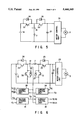
- FIGS. 4 and 5 are circuit diagrams showing a control apparatus of a battery car of the present invention, using a chopper circuit
- FIG. 6 is a circuit diagram showing a control apparatus of a battery car of the present invention, using a voltage control unit for controlling the voltage of the electric-double layered capacitor.
- FIG. 2 is a schematic circuit diagram showing a control apparatus of a battery car according to an embodiment of the present invention.
- FIG. 2 the same elements as shown in FIG. 1 illustrating conventional art are identified with the same reference symbols as used in FIG. 1, and detailed explanations thereof are omitted.
- the motor control unit 20 of FIG. 2 has the same structure as in the conventional circuit of FIG. 1, the current control unit 4 therein is not depicted.
- a motor 3 is not directly driven by a battery 6, but by an electric double-layered capacitor 21.
- the electric double-layered capacitor 21, which has been put to practical use recently, has a large capacitance, i.e., 1000 times or greater than that of the capacitor 2 of the conventional circuit shown in FIG. 1.
- the electric double-layered capacitor 21 is connected in parallel on a bus line P-N of the DC main circuit, as shown in FIG. 2.
- Diodes 24 and 25 are inverse-parallel connected to switch elements 22 and 23, respectively.
- the switch elements 22 and 23 are connected in series via a reactor 7 between the battery 6 and the positive electrode of the electric double-layered capacitor 21.
- the switch element 22 allows a current to flow only from the battery 6 to the electric double-layered capacitor 21 and the switch element 23 allows a current to flow only from the electric double-layered capacitor 21 to the battery 6.
- Diodes 26 and 27 serve to allow a free wheel current to flow during a PWM (pulse width modulation) control.
- a current control unit 28 turns on/off the switch element 22 to control a current supplied from the battery 6 to the electric double-layered capacitor 21.
- a bipolar transistor, MOSFET, IGBT, or Static Inductor thyristor can be used as the switch elements 22 and 23.
- the current control unit 28 compares a current value detected by a current detection unit 19 with a predetermined reference current I 4 to perform a PWM control of the switch element 22.
- the current supplied from the battery 6 to the electric double-layered capacitor 21 is controlled to be the value of the current 14 or less. Since the current is thus controlled by the current control unit 28 and the switch element 22, the current of the electric double-layered capacitor 21 and the capacitor 2 being the discharge current of the battery 6 is not over the current I 4 , the double-layered capacitor 21 is charged with a constant current (I 4 ) until the charging voltage reaches the battery voltage V B .
- the motor 3 is driven in the same manner as in the conventional apparatus mainly by the charge (sometimes called "energy") stored in the electric double-layered capacitor 21.
- the motor 3 When the motor 3 is rotated at a desired rate and deceleration torque is generated, regeneration power is generated from the main circuit unit 1 and a charging current flows through the electric double-layered capacitor 21, with the result that the charge stored in the capacitor 21 is increased.
- the charging current flows through the battery 6 via the switch element 23, the reactor 7, and the diode. 24.
- the charging current is controlled to be a reference current 13 by means of the current control unit 15 by the PWM control of the switch element 23.
- the voltage control unit 14 When the battery voltage V B of the battery 6 reaches the predetermined voltage V 1 , the voltage control unit 14 outputs the reference current I 3 of 0 to the current control unit 15, thereby turning off the switch element 23 to cease the charging of the battery 6.
- the maximum value of the reference current I 3 is limited to or less than the allowable charging current of the battery 6 in the same manner as in the conventional apparatus.
- the motor 3 When the battery car runs on a long downward slope, the motor 3 generates braking torque, and regeneration power is generated by the main circuit unit 1, so that the charge stored in the electric double-layered capacitor 21 may be greater than the charge stored in the initial charging operation. In this case, the battery 6 is fully charged and excess charge is stored only in the double-layered capacitor 21. As a result, the charging voltage V C of the electric double-layered capacitor 21 becomes greater than the battery voltage V B .
- the charging energy of electric double-layered capacitor 21 is discharged as heat energy by a discharge resistor (not shown), in the same manner as in the conventional apparatus, before it exceeds the rated voltage of the main circuit element. Thus, the electric double-layered capacitor 21 is prevented from overcharge.
- FIG. 3 shows an example of change of the battery voltage V B and the charging voltage V C of the electric double-layered capacitor 21 while the battery car is driven.
- both the battery voltage V B and the charging voltage V C of the capacitor are equal to the predetermined voltage V 1 of the battery, at a time t 1 , i.e., the apparatus is in the state where the initial charging operation has been completed.
- the battery car In a period from the time t 4 to a time t 5 , the battery car is stationary. In this state, the voltage V C of the electric double-layered capacitor 21 is maintained at a substantially constant value.
- the motor 3 restarts motoring, the motor 3 is driven only by the charge stored in the electric double-layered capacitor 21 and only the voltage V C of the capacitor 21 is reduced.
- a declaration operation starts at a time t 6 , regeneration power is generated by the main circuit unit 1 and the capacitor 21 is charged with the regeneration power. Therefore, the voltage V C of the electric double-layered capacitor 21 is increased again until a time t 7 when the battery car is stopped.
- the electric double-layered capacitor 21 allows a relatively large charge/discharge current to flow therethrough, it can be used a position where charging or discharging is performed frequently.
- the switch element 22 is kept on even after the initial charging operation is completed. However, it can be turned off at the time t 1 and restart a PWM control when the charging voltage V C of the electric double-layered capacitor 21 is reduced to the voltage V L , so that energy is discharged from the battery 6. With this method, the number of charging/discharging operations of the battery 6 can be reduced, thereby prolonging the lifetime of the battery 6.
- FIGS. 4 and 5 show chopper circuits which can be used as a main circuit for transferring energy between the battery 6 and the electric double-layered capacitor 21.
- the elements shown in FIG. 2 are identified with the same reference numerals as in FIG. 2 and detailed descriptions thereof are omitted.
- FIGS. 4 and 5 show only main portions which differ from FIG. 2.
- the circuit shown in FIG. 4 differs from that of FIG. 2 only in that switch elements 30 and 31 are additionally provided. In this circuit, energy is transferred in the following manner.
- the circuit shown in FIG. 5 differs from that of FIG. 2 in that the polarity of the battery 6 is reversed, the reactor 7 is connected in parallel with switch elements 32 and 33, and the switch element 32 has a function which differs from that of the switch element 22.
- a voltage control unit 36 for controlling the voltage of the electric double-layered capacitor 21 may be provided in the above circuit shown in FIG. 4 or 5.
- the output of the voltage control unit 36 is supplied as the reference current I 4 shown in FIG. 2 to a current control unit 28.
- This arrangement is shown in FIG. 6. With this circuit arrangement, since rated voltages of the battery 6 and the electric double-layered capacitor 21 can be set to desired values, a convenient control apparatus can be obtained. To apply the control circuit shown in FIG. 6 to the circuit shown in FIG. 5, it is only necessary to connect outputs of the current control units 15 and 28 with the switch elements 33 and 32, respectively.
- the DC motor 3 is used in the above embodiment, it can be replaced by an AC motor.
- an inverter which can perform power-regenerating operation is used as the motor control unit 20.
- the battery car is driven and stopped only by means of the motor 3.
- the motor 3 may be used as a driving means auxiliary to an engine (internal-combustion engine), as mentioned in the description of the related art.
- the motor 3 may be used as a main driving means with an engine as an auxiliary driving means.
Abstract
Description
Claims (10)
Applications Claiming Priority (2)
| Application Number | Priority Date | Filing Date | Title |
|---|---|---|---|
| JP4-125263 | 1992-05-19 | ||
| JP12526392A JP3226599B2 (en) | 1992-05-19 | 1992-05-19 | Battery car control method and device |
Publications (1)
| Publication Number | Publication Date |
|---|---|
| US5446365A true US5446365A (en) | 1995-08-29 |
Family
ID=14905756
Family Applications (1)
| Application Number | Title | Priority Date | Filing Date |
|---|---|---|---|
| US08/062,569 Expired - Lifetime US5446365A (en) | 1992-05-19 | 1993-05-18 | Method and apparatus for controlling a battery car |
Country Status (6)
| Country | Link |
|---|---|
| US (1) | US5446365A (en) |
| EP (1) | EP0570934B1 (en) |
| JP (1) | JP3226599B2 (en) |
| KR (1) | KR0182338B1 (en) |
| CN (1) | CN1030247C (en) |
| DE (1) | DE69303977T2 (en) |
Cited By (49)
| Publication number | Priority date | Publication date | Assignee | Title |
|---|---|---|---|---|
| US5670859A (en) * | 1995-06-23 | 1997-09-23 | General Resource Corporation | Feedback control of an inverter output bridge and motor system |
| US5684383A (en) * | 1995-09-19 | 1997-11-04 | Nissan Motor Co., Ltd. | Regenerative charge control system estimating allowable regenerative power |
| US5717310A (en) * | 1995-12-08 | 1998-02-10 | Honda Giken Kogyo Kabushiki Kaisha | Power supply control device for electric vehicle |
| US5742142A (en) * | 1996-08-09 | 1998-04-21 | Delco Electronics Corp. | Low radiated emission motor speed control with PWM regulator |
| US5877926A (en) * | 1997-10-10 | 1999-03-02 | Moisin; Mihail S. | Common mode ground fault signal detection circuit |
| EP0923183A2 (en) * | 1997-11-10 | 1999-06-16 | TOKYO R & D CO. LTD. | Power source unit and electric vehicle loaded therewith |
| US6016049A (en) * | 1998-06-24 | 2000-01-18 | Teleflex Incorporated | Capacitive supercharger for electric shift mechanism |
| US6020688A (en) * | 1997-10-10 | 2000-02-01 | Electro-Mag International, Inc. | Converter/inverter full bridge ballast circuit |
| US6028399A (en) * | 1998-06-23 | 2000-02-22 | Electro-Mag International, Inc. | Ballast circuit with a capacitive and inductive feedback path |
| US6069455A (en) * | 1998-04-15 | 2000-05-30 | Electro-Mag International, Inc. | Ballast having a selectively resonant circuit |
| US6091288A (en) * | 1998-05-06 | 2000-07-18 | Electro-Mag International, Inc. | Inverter circuit with avalanche current prevention |
| US6100648A (en) * | 1999-04-30 | 2000-08-08 | Electro-Mag International, Inc. | Ballast having a resonant feedback circuit for linear diode operation |
| US6100645A (en) * | 1998-06-23 | 2000-08-08 | Electro-Mag International, Inc. | Ballast having a reactive feedback circuit |
| US6107750A (en) * | 1998-09-03 | 2000-08-22 | Electro-Mag International, Inc. | Converter/inverter circuit having a single switching element |
| US6127786A (en) * | 1998-10-16 | 2000-10-03 | Electro-Mag International, Inc. | Ballast having a lamp end of life circuit |
| US6137233A (en) * | 1998-10-16 | 2000-10-24 | Electro-Mag International, Inc. | Ballast circuit with independent lamp control |
| US6160358A (en) * | 1998-09-03 | 2000-12-12 | Electro-Mag International, Inc. | Ballast circuit with lamp current regulating circuit |
| US6169375B1 (en) | 1998-10-16 | 2001-01-02 | Electro-Mag International, Inc. | Lamp adaptable ballast circuit |
| US6181082B1 (en) | 1998-10-15 | 2001-01-30 | Electro-Mag International, Inc. | Ballast power control circuit |
| US6181083B1 (en) | 1998-10-16 | 2001-01-30 | Electro-Mag, International, Inc. | Ballast circuit with controlled strike/restart |
| US6188553B1 (en) | 1997-10-10 | 2001-02-13 | Electro-Mag International | Ground fault protection circuit |
| US6222326B1 (en) | 1998-10-16 | 2001-04-24 | Electro-Mag International, Inc. | Ballast circuit with independent lamp control |
| US6333611B1 (en) * | 1998-11-05 | 2001-12-25 | Nisso Electric Company | Motor drive apparatus for an injection molding machine |
| US20040008530A1 (en) * | 2002-06-05 | 2004-01-15 | Kabushiki Kaisha Toshiba | Inverter control device and electric vehicle thereof |
| US6713894B1 (en) * | 1997-12-11 | 2004-03-30 | Bayerische Motoren Werke Aktiengesellschaft | Device for supplying electricity to a motor vehicle |
| US20050179412A1 (en) * | 2002-04-12 | 2005-08-18 | Valeo Equipements Electriques Moteur | Arrangement for carrying out a method for a controlling a multi-phased and reversible rotating electrical machine associated with a heat engine of a motor vehicle |
| US20070018501A1 (en) * | 2005-07-21 | 2007-01-25 | Wolfgang Schon | Method and device for electric supply of electric setting mechanisms for motor vehicles |
| US7417407B1 (en) * | 2004-10-13 | 2008-08-26 | The University Of Toledo | Circuit with a switch for charging a battery in a battery capacitor circuit |
| US20080238527A1 (en) * | 2003-10-06 | 2008-10-02 | Siemens Ag | Switching Device for Bi-Directionally Equalizing Charge Between Energy Accumulators and Corresponding Methods |
| US7479753B1 (en) * | 2004-02-24 | 2009-01-20 | Nvidia Corporation | Fan speed controller |
| US20090204830A1 (en) * | 2008-02-11 | 2009-08-13 | Nvidia Corporation | Power management with dynamic frequency dajustments |
| US20090200991A1 (en) * | 2005-11-09 | 2009-08-13 | Matsushita Electric Industrial Co., Ltd. | Power supply system |
| US7849332B1 (en) | 2002-11-14 | 2010-12-07 | Nvidia Corporation | Processor voltage adjustment system and method |
| US7882369B1 (en) | 2002-11-14 | 2011-02-01 | Nvidia Corporation | Processor performance adjustment system and method |
| US7886164B1 (en) | 2002-11-14 | 2011-02-08 | Nvidia Corporation | Processor temperature adjustment system and method |
| US20110308078A1 (en) * | 2010-06-17 | 2011-12-22 | Varian Semiconductor Equipment Associates, Inc. | Technique for limiting transmission of fault current |
| US8839006B2 (en) | 2010-05-28 | 2014-09-16 | Nvidia Corporation | Power consumption reduction systems and methods |
| US9134782B2 (en) | 2007-05-07 | 2015-09-15 | Nvidia Corporation | Maintaining optimum voltage supply to match performance of an integrated circuit |
| US9209719B2 (en) | 2010-10-05 | 2015-12-08 | Toyota Jidosha Kabushiki Kaisha | Load driving device and inverted movable body equipped with same |
| US9256265B2 (en) | 2009-12-30 | 2016-02-09 | Nvidia Corporation | Method and system for artificially and dynamically limiting the framerate of a graphics processing unit |
| US9325188B2 (en) | 2012-12-26 | 2016-04-26 | Colorado Energy Research Technologies, LLC | Power recovery controller |
| US20160138550A1 (en) * | 2013-06-13 | 2016-05-19 | Unison Industries, Llc | Method to decouple battery from high level cranking currents of diesel engines |
| US9428069B2 (en) | 2012-12-26 | 2016-08-30 | Colorado Energy Research Technologies, LLC | Systems and methods for efficiently charging power recovery controller |
| US20170085101A1 (en) * | 2014-10-03 | 2017-03-23 | Elitise Llc | Battery module architecture with horizontal and vertical expandability |
| US20170110900A1 (en) * | 2014-04-02 | 2017-04-20 | Bookleaf Pty Ltd | Battery management system and method and battery powered appliance incorporating the same |
| US9830889B2 (en) | 2009-12-31 | 2017-11-28 | Nvidia Corporation | Methods and system for artifically and dynamically limiting the display resolution of an application |
| US9834100B2 (en) | 2012-11-12 | 2017-12-05 | Volvo Truck Corporation | Charge/discharge system |
| US20190372179A1 (en) * | 2018-06-05 | 2019-12-05 | International Business Machines Corporation | Battery pack capacity optimization via self-regulation of cell temperature |
| US11863062B2 (en) * | 2018-04-27 | 2024-01-02 | Raytheon Company | Capacitor discharge circuit |
Families Citing this family (30)
| Publication number | Priority date | Publication date | Assignee | Title |
|---|---|---|---|---|
| JP3178503B2 (en) * | 1994-07-01 | 2001-06-18 | 株式会社デンソー | Hybrid vehicle control device |
| FR2722738B1 (en) * | 1994-07-01 | 1997-12-05 | Nippon Denso Co | CONTROL DEVICE FOR USE IN A STANDARD HYBRID AUTOMOBILE |
| JPH08130805A (en) * | 1994-10-31 | 1996-05-21 | Okamura Kenkyusho:Kk | Electric automobile |
| JP3089958B2 (en) * | 1994-12-06 | 2000-09-18 | 三菱自動車工業株式会社 | Electric vehicle braking control device |
| US5587250A (en) * | 1995-09-27 | 1996-12-24 | Motorola, Inc. | Hybrid energy storage system |
| JPH10271611A (en) * | 1997-03-25 | 1998-10-09 | Nissan Diesel Motor Co Ltd | Power supply system for electric vehicle |
| FR2790147B1 (en) * | 1999-02-19 | 2003-09-26 | Sagem | DEVICE FOR TRANSFERRING CHARGE CURRENT BETWEEN TWO BATTERIES |
| KR100495685B1 (en) * | 1999-06-11 | 2005-06-16 | 브룩스 오토메이션, 인크. | Ultracapacitor power supply for an electric vehicle |
| JP2001268900A (en) * | 2000-03-22 | 2001-09-28 | Masayuki Hattori | Bi-directional step-up and step-down chopper circuit |
| JP2002281609A (en) * | 2001-03-21 | 2002-09-27 | Masayuki Hattori | Combined secondary battery circuit and regenerative control system |
| CN101232198A (en) * | 2002-12-16 | 2008-07-30 | 三菱电机株式会社 | Power unit for automobile |
| JP2005341667A (en) * | 2004-05-25 | 2005-12-08 | Motor Jidosha Kk | Power unit and controller for electric vehicle |
| JP4593973B2 (en) * | 2004-05-26 | 2010-12-08 | トヨタ自動車株式会社 | Motor drive device |
| JP4839722B2 (en) * | 2005-08-08 | 2011-12-21 | トヨタ自動車株式会社 | Vehicle power supply |
| US7489048B2 (en) * | 2006-01-09 | 2009-02-10 | General Electric Company | Energy storage system for electric or hybrid vehicle |
| JP4804994B2 (en) * | 2006-04-05 | 2011-11-02 | 株式会社小松製作所 | Forklift power supply |
| JP4779947B2 (en) * | 2006-11-24 | 2011-09-28 | 日産自動車株式会社 | Vehicle power supply device |
| FR2933647B1 (en) * | 2008-07-10 | 2010-08-20 | Peugeot Citroen Automobiles Sa | ENERGY STORAGE SYSTEM FOR MOTOR VEHICLE OF ELECTRIC OR HYBRID TYPE AND RECHARGE SYSTEM COMPRISING SUCH A STORAGE SYSTEM |
| FR2949099B1 (en) * | 2009-08-11 | 2011-09-30 | Daniel Giudice | METHOD FOR CONTROLLING A PROPULSION ELECTRIC MOTOR UNIT OF A VEHICLE |
| JP5234052B2 (en) * | 2010-04-27 | 2013-07-10 | 株式会社デンソー | Power supply |
| JP5576722B2 (en) * | 2010-06-14 | 2014-08-20 | 本田技研工業株式会社 | Overvoltage suppressing device and motor driving device |
| FR2975243B1 (en) * | 2011-05-13 | 2013-04-26 | Michelin Soc Tech | DEVICE AND METHOD FOR MANAGING THE ELECTRIC BRAKE OF A VEHICLE |
| KR101301760B1 (en) * | 2012-01-31 | 2013-08-29 | 조선대학교산학협력단 | electric energy charging and discharging apparatus for regenerative braking system of electric motorcycles |
| DE102012222928A1 (en) * | 2012-12-12 | 2014-06-12 | Robert Bosch Gmbh | Precharge circuit for charging a DC link capacitor |
| WO2014182291A1 (en) * | 2013-05-08 | 2014-11-13 | Otis Elevator Company | Hybrid energy sourced battery or super-capacitor fed drive topologies |
| WO2015098790A1 (en) * | 2013-12-27 | 2015-07-02 | 株式会社 村田製作所 | Battery pack |
| CN104960429B (en) * | 2015-07-21 | 2017-07-04 | 清华大学 | The power distribution means and energy distributing method of a kind of city electric bus compound energy |
| CN104960431B (en) * | 2015-07-21 | 2017-07-04 | 哈尔滨理工大学 | A kind of power distribution means and energy distributing method based on lithium-rich manganese-based lithium battery motor-car |
| JP6554972B2 (en) * | 2015-07-28 | 2019-08-07 | 日産自動車株式会社 | Power supply |
| EP3471263A4 (en) * | 2016-06-13 | 2020-04-22 | Mitsuba Corporation | Sr motor control system and sr motor control method |
Citations (11)
| Publication number | Priority date | Publication date | Assignee | Title |
|---|---|---|---|---|
| US4054826A (en) * | 1975-03-10 | 1977-10-18 | Wahlstrom Sven E | Method and apparatus for charging batteries using variable capacitors |
| US4330742A (en) * | 1980-04-11 | 1982-05-18 | Eberhart Reimers | Circuitry for recovering electrical energy with an electric vehicle DC propulsion motor when braking |
| CH633751A5 (en) * | 1979-11-28 | 1982-12-31 | Lambert Sovauto Sa | Self-propelled electric vehicle |
| US4689531A (en) * | 1985-07-01 | 1987-08-25 | Ewers, And Willis | Electric regeneration apparatus and method for driving a load |
| EP0280478A2 (en) * | 1987-02-20 | 1988-08-31 | Fki Cableform Limited | Regenerative braking systems |
| JPH0271072A (en) * | 1988-09-06 | 1990-03-09 | Fuji Electric Co Ltd | Extention system for cooling water supplying device |
| US4963811A (en) * | 1987-12-10 | 1990-10-16 | Weber Hans R | Method and apparatus for powering electrical and electronic consuming devices with solar energy |
| EP0418995A1 (en) * | 1989-09-21 | 1991-03-27 | Isuzu Motors Limited | Energy recovery system for motor vehicle |
| US5053632A (en) * | 1987-02-18 | 1991-10-01 | Hino Jidosha Kogyo Kabushiki Kaisha | Electric braking and auxiliary engine mechanism for a motor vehicle |
| US5119010A (en) * | 1989-07-27 | 1992-06-02 | Isuzu Motors Limited | Power supply device |
| US5260637A (en) * | 1991-09-18 | 1993-11-09 | MAGNETI MARELLI S.p.A. | Electrical system for a motor vehicle, including at least one supercapacitor |
-
1992
- 1992-05-19 JP JP12526392A patent/JP3226599B2/en not_active Expired - Lifetime
-
1993
- 1993-05-17 KR KR1019930008406A patent/KR0182338B1/en not_active IP Right Cessation
- 1993-05-18 US US08/062,569 patent/US5446365A/en not_active Expired - Lifetime
- 1993-05-19 CN CN93106246A patent/CN1030247C/en not_active Expired - Lifetime
- 1993-05-19 EP EP93108168A patent/EP0570934B1/en not_active Expired - Lifetime
- 1993-05-19 DE DE69303977T patent/DE69303977T2/en not_active Expired - Fee Related
Patent Citations (11)
| Publication number | Priority date | Publication date | Assignee | Title |
|---|---|---|---|---|
| US4054826A (en) * | 1975-03-10 | 1977-10-18 | Wahlstrom Sven E | Method and apparatus for charging batteries using variable capacitors |
| CH633751A5 (en) * | 1979-11-28 | 1982-12-31 | Lambert Sovauto Sa | Self-propelled electric vehicle |
| US4330742A (en) * | 1980-04-11 | 1982-05-18 | Eberhart Reimers | Circuitry for recovering electrical energy with an electric vehicle DC propulsion motor when braking |
| US4689531A (en) * | 1985-07-01 | 1987-08-25 | Ewers, And Willis | Electric regeneration apparatus and method for driving a load |
| US5053632A (en) * | 1987-02-18 | 1991-10-01 | Hino Jidosha Kogyo Kabushiki Kaisha | Electric braking and auxiliary engine mechanism for a motor vehicle |
| EP0280478A2 (en) * | 1987-02-20 | 1988-08-31 | Fki Cableform Limited | Regenerative braking systems |
| US4963811A (en) * | 1987-12-10 | 1990-10-16 | Weber Hans R | Method and apparatus for powering electrical and electronic consuming devices with solar energy |
| JPH0271072A (en) * | 1988-09-06 | 1990-03-09 | Fuji Electric Co Ltd | Extention system for cooling water supplying device |
| US5119010A (en) * | 1989-07-27 | 1992-06-02 | Isuzu Motors Limited | Power supply device |
| EP0418995A1 (en) * | 1989-09-21 | 1991-03-27 | Isuzu Motors Limited | Energy recovery system for motor vehicle |
| US5260637A (en) * | 1991-09-18 | 1993-11-09 | MAGNETI MARELLI S.p.A. | Electrical system for a motor vehicle, including at least one supercapacitor |
Cited By (60)
| Publication number | Priority date | Publication date | Assignee | Title |
|---|---|---|---|---|
| US5670859A (en) * | 1995-06-23 | 1997-09-23 | General Resource Corporation | Feedback control of an inverter output bridge and motor system |
| US5684383A (en) * | 1995-09-19 | 1997-11-04 | Nissan Motor Co., Ltd. | Regenerative charge control system estimating allowable regenerative power |
| US5717310A (en) * | 1995-12-08 | 1998-02-10 | Honda Giken Kogyo Kabushiki Kaisha | Power supply control device for electric vehicle |
| US5742142A (en) * | 1996-08-09 | 1998-04-21 | Delco Electronics Corp. | Low radiated emission motor speed control with PWM regulator |
| US5877926A (en) * | 1997-10-10 | 1999-03-02 | Moisin; Mihail S. | Common mode ground fault signal detection circuit |
| US6020688A (en) * | 1997-10-10 | 2000-02-01 | Electro-Mag International, Inc. | Converter/inverter full bridge ballast circuit |
| US6188553B1 (en) | 1997-10-10 | 2001-02-13 | Electro-Mag International | Ground fault protection circuit |
| US6281638B1 (en) | 1997-10-10 | 2001-08-28 | Electro-Mag International, Inc. | Converter/inverter full bridge ballast circuit |
| EP0923183A2 (en) * | 1997-11-10 | 1999-06-16 | TOKYO R & D CO. LTD. | Power source unit and electric vehicle loaded therewith |
| US6713894B1 (en) * | 1997-12-11 | 2004-03-30 | Bayerische Motoren Werke Aktiengesellschaft | Device for supplying electricity to a motor vehicle |
| US6236168B1 (en) | 1998-04-15 | 2001-05-22 | Electro-Mag International, Inc. | Ballast instant start circuit |
| US6069455A (en) * | 1998-04-15 | 2000-05-30 | Electro-Mag International, Inc. | Ballast having a selectively resonant circuit |
| US6091288A (en) * | 1998-05-06 | 2000-07-18 | Electro-Mag International, Inc. | Inverter circuit with avalanche current prevention |
| US6028399A (en) * | 1998-06-23 | 2000-02-22 | Electro-Mag International, Inc. | Ballast circuit with a capacitive and inductive feedback path |
| US6100645A (en) * | 1998-06-23 | 2000-08-08 | Electro-Mag International, Inc. | Ballast having a reactive feedback circuit |
| US6016049A (en) * | 1998-06-24 | 2000-01-18 | Teleflex Incorporated | Capacitive supercharger for electric shift mechanism |
| US6160358A (en) * | 1998-09-03 | 2000-12-12 | Electro-Mag International, Inc. | Ballast circuit with lamp current regulating circuit |
| US6107750A (en) * | 1998-09-03 | 2000-08-22 | Electro-Mag International, Inc. | Converter/inverter circuit having a single switching element |
| US6181082B1 (en) | 1998-10-15 | 2001-01-30 | Electro-Mag International, Inc. | Ballast power control circuit |
| US6181083B1 (en) | 1998-10-16 | 2001-01-30 | Electro-Mag, International, Inc. | Ballast circuit with controlled strike/restart |
| US6222326B1 (en) | 1998-10-16 | 2001-04-24 | Electro-Mag International, Inc. | Ballast circuit with independent lamp control |
| US6137233A (en) * | 1998-10-16 | 2000-10-24 | Electro-Mag International, Inc. | Ballast circuit with independent lamp control |
| US6127786A (en) * | 1998-10-16 | 2000-10-03 | Electro-Mag International, Inc. | Ballast having a lamp end of life circuit |
| US6169375B1 (en) | 1998-10-16 | 2001-01-02 | Electro-Mag International, Inc. | Lamp adaptable ballast circuit |
| US6333611B1 (en) * | 1998-11-05 | 2001-12-25 | Nisso Electric Company | Motor drive apparatus for an injection molding machine |
| US6100648A (en) * | 1999-04-30 | 2000-08-08 | Electro-Mag International, Inc. | Ballast having a resonant feedback circuit for linear diode operation |
| US20050179412A1 (en) * | 2002-04-12 | 2005-08-18 | Valeo Equipements Electriques Moteur | Arrangement for carrying out a method for a controlling a multi-phased and reversible rotating electrical machine associated with a heat engine of a motor vehicle |
| US20040008530A1 (en) * | 2002-06-05 | 2004-01-15 | Kabushiki Kaisha Toshiba | Inverter control device and electric vehicle thereof |
| US7057361B2 (en) * | 2002-06-05 | 2006-06-06 | Kabushiki Kaisha Toshiba | Inverter control device and electric vehicle thereof |
| US7886164B1 (en) | 2002-11-14 | 2011-02-08 | Nvidia Corporation | Processor temperature adjustment system and method |
| US7882369B1 (en) | 2002-11-14 | 2011-02-01 | Nvidia Corporation | Processor performance adjustment system and method |
| US7849332B1 (en) | 2002-11-14 | 2010-12-07 | Nvidia Corporation | Processor voltage adjustment system and method |
| US7714544B2 (en) | 2003-10-06 | 2010-05-11 | Siemens Aktiengesellschaft | Switching device for bi-directionally equalizing charge between energy accumulators and corresponding methods |
| US20080238527A1 (en) * | 2003-10-06 | 2008-10-02 | Siemens Ag | Switching Device for Bi-Directionally Equalizing Charge Between Energy Accumulators and Corresponding Methods |
| US7479753B1 (en) * | 2004-02-24 | 2009-01-20 | Nvidia Corporation | Fan speed controller |
| US7417407B1 (en) * | 2004-10-13 | 2008-08-26 | The University Of Toledo | Circuit with a switch for charging a battery in a battery capacitor circuit |
| US20070018501A1 (en) * | 2005-07-21 | 2007-01-25 | Wolfgang Schon | Method and device for electric supply of electric setting mechanisms for motor vehicles |
| US20090200991A1 (en) * | 2005-11-09 | 2009-08-13 | Matsushita Electric Industrial Co., Ltd. | Power supply system |
| US7679337B2 (en) * | 2005-11-09 | 2010-03-16 | Panasonic Corporation | Power supply system |
| US9134782B2 (en) | 2007-05-07 | 2015-09-15 | Nvidia Corporation | Maintaining optimum voltage supply to match performance of an integrated circuit |
| US20090204830A1 (en) * | 2008-02-11 | 2009-08-13 | Nvidia Corporation | Power management with dynamic frequency dajustments |
| US8370663B2 (en) | 2008-02-11 | 2013-02-05 | Nvidia Corporation | Power management with dynamic frequency adjustments |
| US8775843B2 (en) | 2008-02-11 | 2014-07-08 | Nvidia Corporation | Power management with dynamic frequency adjustments |
| US9256265B2 (en) | 2009-12-30 | 2016-02-09 | Nvidia Corporation | Method and system for artificially and dynamically limiting the framerate of a graphics processing unit |
| US9830889B2 (en) | 2009-12-31 | 2017-11-28 | Nvidia Corporation | Methods and system for artifically and dynamically limiting the display resolution of an application |
| US8839006B2 (en) | 2010-05-28 | 2014-09-16 | Nvidia Corporation | Power consumption reduction systems and methods |
| US8739396B2 (en) * | 2010-06-17 | 2014-06-03 | Varian Semiconductor Equipment Associates, Inc. | Technique for limiting transmission of fault current |
| US20110308078A1 (en) * | 2010-06-17 | 2011-12-22 | Varian Semiconductor Equipment Associates, Inc. | Technique for limiting transmission of fault current |
| US9209719B2 (en) | 2010-10-05 | 2015-12-08 | Toyota Jidosha Kabushiki Kaisha | Load driving device and inverted movable body equipped with same |
| US9834100B2 (en) | 2012-11-12 | 2017-12-05 | Volvo Truck Corporation | Charge/discharge system |
| US9325188B2 (en) | 2012-12-26 | 2016-04-26 | Colorado Energy Research Technologies, LLC | Power recovery controller |
| US9428069B2 (en) | 2012-12-26 | 2016-08-30 | Colorado Energy Research Technologies, LLC | Systems and methods for efficiently charging power recovery controller |
| US9689366B2 (en) * | 2013-06-13 | 2017-06-27 | Unison Industries, Llc | Method to decouple battery from high level cranking currents of diesel engines |
| US20160138550A1 (en) * | 2013-06-13 | 2016-05-19 | Unison Industries, Llc | Method to decouple battery from high level cranking currents of diesel engines |
| US20170110900A1 (en) * | 2014-04-02 | 2017-04-20 | Bookleaf Pty Ltd | Battery management system and method and battery powered appliance incorporating the same |
| US20170085101A1 (en) * | 2014-10-03 | 2017-03-23 | Elitise Llc | Battery module architecture with horizontal and vertical expandability |
| US9917448B2 (en) * | 2014-10-03 | 2018-03-13 | Elitise Llc | Battery module architecture with horizontal and vertical expandability |
| US11863062B2 (en) * | 2018-04-27 | 2024-01-02 | Raytheon Company | Capacitor discharge circuit |
| US20190372179A1 (en) * | 2018-06-05 | 2019-12-05 | International Business Machines Corporation | Battery pack capacity optimization via self-regulation of cell temperature |
| US10903534B2 (en) * | 2018-06-05 | 2021-01-26 | International Business Machines Corporation | Battery pack capacity optimization via self-regulation of cell temperature |
Also Published As
| Publication number | Publication date |
|---|---|
| CN1030247C (en) | 1995-11-15 |
| EP0570934A2 (en) | 1993-11-24 |
| EP0570934A3 (en) | 1994-06-01 |
| EP0570934B1 (en) | 1996-08-14 |
| JP3226599B2 (en) | 2001-11-05 |
| DE69303977T2 (en) | 1997-01-16 |
| DE69303977D1 (en) | 1996-09-19 |
| KR0182338B1 (en) | 1999-05-15 |
| JPH05328533A (en) | 1993-12-10 |
| CN1080243A (en) | 1994-01-05 |
| KR930023212A (en) | 1993-12-18 |
Similar Documents
| Publication | Publication Date | Title |
|---|---|---|
| US5446365A (en) | Method and apparatus for controlling a battery car | |
| US5406126A (en) | Hybrid drive system with regeneration for motor vehicles and the like | |
| US6995480B2 (en) | Power supply equipment for motor vehicle with inverter for controlling motor generator | |
| US5285862A (en) | Power supply system for hybrid vehicles | |
| US5723956A (en) | Low cost electronic ultracapacitor interface technique to provide load leveling of a battery for pulsed load or motor traction drive applications | |
| JPH10164709A (en) | Power supply unit and power supply unit for electric vehicle | |
| KR880010969A (en) | Electric Power Steering Control | |
| JP4048787B2 (en) | Load drive device | |
| KR100654144B1 (en) | Control device for motor-driven 4wd vehicle and related method | |
| JPH05328530A (en) | Power source for hybrid vehicle | |
| WO2009028302A1 (en) | Vehicle step-up converter circuit | |
| JP3612572B2 (en) | Motor drive power supply | |
| JP3794224B2 (en) | Vehicle power supply | |
| JPH06113407A (en) | Power source for energy regenerating system of railroad car | |
| JP3289411B2 (en) | Voltage control device for vehicle generator | |
| JPH09163756A (en) | Electric discharge circuit for capacitor | |
| JPH08251711A (en) | Battery apparatus for hybrid automobile | |
| JPH0549101A (en) | Power supply protective circuit for vehicle | |
| JPS6115535A (en) | Generation control system of alternator | |
| GB2062380A (en) | Regenerative braking systems for D.C. motors | |
| JPH1014222A (en) | Step down type dc-dc converter corresponding to regenerated power | |
| JPH0795701A (en) | Rotary electric machine controller | |
| KR102257527B1 (en) | Regenerating brake system for an electric vehicle | |
| JP3266392B2 (en) | Power supply for vehicles | |
| KR20050035343A (en) | Regeneration energy control method of electric vehicle |
Legal Events
| Date | Code | Title | Description |
|---|---|---|---|
| STPP | Information on status: patent application and granting procedure in general |
Free format text: APPLICATION UNDERGOING PREEXAM PROCESSING |
|
| AS | Assignment |
Owner name: HINO JIDOSHA KOGYO KABUSHIKI KAISHA, JAPAN Free format text: ASSIGNMENT OF ASSIGNORS INTEREST;ASSIGNORS:NOMURA, YOSHIHITO;ENDO, KOJI;OKADO, CHIHIRO;REEL/FRAME:006604/0613 Effective date: 19930512 Owner name: KABUSHIKI KAISHA TOSHIBA, JAPAN Free format text: ASSIGNMENT OF ASSIGNORS INTEREST;ASSIGNORS:NOMURA, YOSHIHITO;ENDO, KOJI;OKADO, CHIHIRO;REEL/FRAME:006604/0613 Effective date: 19930512 |
|
| FPAY | Fee payment |
Year of fee payment: 4 |
|
| FPAY | Fee payment |
Year of fee payment: 8 |
|
| FPAY | Fee payment |
Year of fee payment: 12 |