US5900025A - Processor having a hierarchical control register file and methods for operating the same - Google Patents
Processor having a hierarchical control register file and methods for operating the same Download PDFInfo
- Publication number
- US5900025A US5900025A US08/528,509 US52850995A US5900025A US 5900025 A US5900025 A US 5900025A US 52850995 A US52850995 A US 52850995A US 5900025 A US5900025 A US 5900025A
- Authority
- US
- United States
- Prior art keywords
- control register
- thread
- context
- control
- level
- Prior art date
- Legal status (The legal status is an assumption and is not a legal conclusion. Google has not performed a legal analysis and makes no representation as to the accuracy of the status listed.)
- Expired - Lifetime
Links
- 238000000034 method Methods 0.000 title abstract description 23
- 230000004048 modification Effects 0.000 claims abstract description 17
- 238000012986 modification Methods 0.000 claims abstract description 17
- 230000004044 response Effects 0.000 claims abstract description 12
- 230000006870 function Effects 0.000 claims description 19
- 239000000872 buffer Substances 0.000 claims description 5
- 230000008569 process Effects 0.000 abstract description 17
- 230000001419 dependent effect Effects 0.000 description 4
- 230000009471 action Effects 0.000 description 2
- 238000005516 engineering process Methods 0.000 description 2
- 230000002349 favourable effect Effects 0.000 description 2
- 230000004075 alteration Effects 0.000 description 1
- 230000001427 coherent effect Effects 0.000 description 1
- 238000001514 detection method Methods 0.000 description 1
- 230000004069 differentiation Effects 0.000 description 1
- 238000007726 management method Methods 0.000 description 1
- 239000000463 material Substances 0.000 description 1
- 238000012913 prioritisation Methods 0.000 description 1
- 230000001360 synchronised effect Effects 0.000 description 1
Images


Classifications
-
- G—PHYSICS
- G06—COMPUTING; CALCULATING OR COUNTING
- G06F—ELECTRIC DIGITAL DATA PROCESSING
- G06F9/00—Arrangements for program control, e.g. control units
- G06F9/06—Arrangements for program control, e.g. control units using stored programs, i.e. using an internal store of processing equipment to receive or retain programs
- G06F9/30—Arrangements for executing machine instructions, e.g. instruction decode
- G06F9/30098—Register arrangements
- G06F9/30101—Special purpose registers
-
- G—PHYSICS
- G06—COMPUTING; CALCULATING OR COUNTING
- G06F—ELECTRIC DIGITAL DATA PROCESSING
- G06F9/00—Arrangements for program control, e.g. control units
- G06F9/06—Arrangements for program control, e.g. control units using stored programs, i.e. using an internal store of processing equipment to receive or retain programs
- G06F9/46—Multiprogramming arrangements
- G06F9/461—Saving or restoring of program or task context
- G06F9/462—Saving or restoring of program or task context with multiple register sets
Definitions
- the present invention relates to the field of computer systems. More specifically, the present invention relates to their processors, in particular, the control registers.
- All computer system processors include a number of control registers 1 for controlling system operations.
- the number of control registers included and their specific usage vary from processor to processor.
- Some processors include only control registers for managing basic system operations, such as instruction fetching/execution (i.e. the program counter register), interrupt/exception handling and so forth.
- Other processors include additional control registers for controlling various hardware and/or operation mode selections, such as whether a processor is to operate in an "enhanced" mode or a backward compatible "emulation” mode, whether certain hardware checking is to be performed, whether certain interrupts are to be recognized, and so forth.
- Yet other processors further include control registers for assisting the operating system in managing system resources, such as memory management, process/context switching, procedure call and return, and so forth.
- control registers are included in an unorganized manner. In other words, there is no particular organizational relationship between one particular/group of control registers provided for one purpose with another particular/group of control registers provided for another purpose. As the number of control registers being provided continues to increase, it is desirable that the control registers be organized in some coherent manner.
- the present invention achieves these and other desirable results.
- a processor is provided with a number of primary control registers logically organized into a hierarchy having two or more control register levels. Under the presently preferred embodiment, the primary control registers are logically organized into three control register levels. At the highest level of the logical hierarchy is a set of control registers for controlling the overall system. At the second highest level of the logical hierarchy is a number of control register sets for controlling concurrent execution of processes in multiple peer contexts (hereinafter simply contexts). At the third highest level of the logical hierarchy is a number of control register sets for controlling concurrent execution of multiple peer process threads (hereinafter simply threads) for each of the concurrently executing peer contexts.
- eight sets of context control registers are provided for concurrently supporting up to eight active contexts, and 64 sets of thread control registers are provided for concurrently supporting up to eight active threads for each of the active contexts.
- Each of the system and context control register sets comprises 32 control registers, whereas each thread control register set comprises 16 control registers.
- the system control register set includes, in particular, a number of active context control registers for storing corresponding basic control information about the concurrently executing active contexts.
- the basic control information includes execution priorities and control register access/modification privileges of the contexts.
- Each context control register set includes, in particular, a number of active thread control registers for storing corresponding basic control information about the concurrently executing active threads.
- the basic control information includes execution priorities and control register access/modification privileges of the threads.
- Each thread control register set includes, in particular, a hardware defined flag register, a software defined flag register, a software flag control register for storing a pointer to a software defined flag array for the thread's context from which the thread's software defined flag register is to be obtained, and a functional unit control register for storing control information for dynamically configuring applicable functional units to the requirements of the thread.
- the system control register set is allocated to and initialized by the operating system during system start up.
- the context and thread control register sets are dynamically allocated to the contexts and threads and initialized by the operating system, when the contexts and threads are spawned by their "parent" processes; except the operating system context, including the "micro-kernel" thread, which is established as part of system start up.
- the "micro-kernel" thread advantageously performs a number of allocation sub-tasks via macro-traps, in particular, the sub-task of saving the state of a context/thread having to be deallocated.
- the processor is further provided with a writeable control store facility, an auxiliary control register file, and an auxiliary operand register file.
- the writeable control store is used for storing the MLRs.
- Subsets of the auxiliary control register file are correspondingly allocated to the MLRs to facilitate their concurrent executions.
- Each subset includes, in particular, a status/command control register for facilitating status/command exchanges between a child MLR and its parent thread.
- the auxiliary operand register file is used by the MLRs during execution.
- the MLRs are invoked in like manner as conventional interrupts and exceptions, in response to detection of the macro-traps.
- the processor is further provided with an enhanced instruction fetch unit for concurrently fetching, decoding and dispatching instructions for the active threads and the MLRs.
- the enhanced instruction fetch unit includes a plurality of fetch buffers, a plurality of decoders, a plurality of dispatch queues, dispatch queue selection circuitry and control circuitry for concurrently fetching, decoding, and dispatching instructions to the functional units for selected ones of the active threads and MLRs. Instructions of the active threads (including their offspring MLRs) are dispatched to the functional units with context and thread identifications, preferably in the form of tags, appended to them.
- selected functional units are enhanced to be responsive to the proper thread level dynamic configuration control information.
- the proper thread level dynamic configuration control information is discerned by the functional units using the appended context and thread identification tags.
- functional unit dynamic configuration is also provided at the instruction level through functional unit control information included as an integral part of the instructions.
- the functional units are further enhanced to be responsive to this integrated dynamic configuration control information.
- control registers are directly accessible and modifiable using instructions of the standard instruction set.
- the instructions include, in particular, a branch-on-flag instruction for effectuating instruction branching based on the values of the hardware/software flags, Boolean instructions for performing logic operations upon the control registers, and a move instruction for moving "data" between the control registers, as well as between the control and operand registers.
- a context and thread based privilege structure that leverages on the manner the control registers are logically organized is employed to control the direct accesses and modifications.
- the functional units are further enhanced to ensure the instructions' threads/contexts have the necessary privileges to access and modify the target control registers.
- the privileges possessed by the instructions' threads/contexts are located using the instructions' appended context and thread identification tags.
- a thread is initially conferred a standard thread privilege, which allows the thread to access and modify its own set of control registers.
- one of the threads of each context can be temporarily conferred a context privilege, which allows the context privileged thread to also access and modify its context's context level control register set as well as its peer threads' control register sets.
- one of the contexts (more specifically, one of the context privileged threads) can be temporarily conferred a system privilege, which allows the system privileged context to also access and modify the system level control register set as well as any one of the other "lower" level control register sets.
- the conditions under which the privileges are dynamically conferred to and withdrawn from the various threads and contexts are implementation dependent.
- the conditions include, in particular, the conditions of encountering certain execution exceptions, under which a thread will be temporarily conferred the privilege for accessing and modifying its context's control register set, and a context will be temporarily conferred the privilege for accessing and modifying the system set of control registers, by the exception service routines, while the exceptions are being serviced.
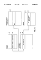
- FIG. 1 illustrates an exemplary processor incorporating the teachings of the present invention
- FIG. 2 illustrates a logical view of the control registers in accordance with the present invention
- FIG. 3 illustrates one embodiment of the control register set at the system level of the logical hierarchy
- FIG. 4 illustrates one embodiment of a control register set at the context level of the logical hierarchy
- FIG. 5 illustrates one embodiment of a control register set at the thread level of the logical hierarchy
- FIG. 6 illustrates one embodiment of a control register set at the macro-trap level of the logical hierarchy
- FIGS. 7a-7c illustrate one embodiment each of selected control registers at the system level of the logical hierarchy
- FIGS. 8a-8c illustrate one embodiment each of selected control registers at the context level of the logical hierarchy
- FIGS. 9a-9e illustrate one embodiment each of selected control registers at the thread level of the logical hierarchy
- FIG. 10 illustrates the relationship between the SWFCTL and VTHRDx -- INFO registers at the context level, the SWFOFST and SWFLAG registers at the thread level, and the SWFLAG array;
- FIGS. 11a-11b illustrate one embodiment of the operational flow for allocating a context level control register set to a context by the operating system
- FIGS. 12a-12b illustrate one embodiment of the operational flow for allocating a thread level control register set to a thread by the context
- FIG. 13 illustrates invocation of an MLR
- FIG. 14 illustrates the operational flow of an exemplary macro-trap for saving the state of a context being deallocated
- FIG. 15 illustrates one embodiment of IFU of FIG. 1
- FIGS. 16a-16d illustrate the instruction format, the Branch-on-flag instruction, the Move instruction, and the Boolean AND instruction for the illustrated processor of FIG. 1.
- FIG. 17 illustrates an exemplary multiply and accumulate functional unit enhanced to perform different variations of multiply and accumulate in response to functional unit dynamic configuration control information maintained for a thread
- FIGS. 18a-18b illustrate an exemplary AND gate and an exemplary Adder enhanced to perform either a Boolean AND or NOR operation, and an Add or a Subtract operation respectively, in response to integral functional unit dynamic configuration control information of an instruction;
- FIG. 19 illustrates an exemplary barrel shifter enhanced to perform different shifting with or without rounding, in response to both types of functional unit dynamic configuration control information
- FIG. 20 illustrates the context and thread based privilege approach for controlling accesses and modifications of the control registers under the presently preferred embodiment.
- Exemplary processor 10 includes primary control register file 20a of the present invention, instruction fetch unit (IFU) 12 and execution units 14, both incorporated with the teachings of the present invention. Additionally, processor 10 includes operand register file 22a, instruction cache (I-cache) 16, and data cache (D-cache) 18. Preferably, processor 10 further includes auxiliary control register file 20b, auxiliary operand register file (AORF) 22b, writeable control store facility (WCSF) 26 and multiplexor 24. These elements are coupled to each other as shown.
- IFU instruction fetch unit
- execution units 14 both incorporated with the teachings of the present invention.
- processor 10 includes operand register file 22a, instruction cache (I-cache) 16, and data cache (D-cache) 18.
- processor 10 further includes auxiliary control register file 20b, auxiliary operand register file (AORF) 22b, writeable control store facility (WCSF) 26 and multiplexor 24. These elements are coupled to each other as shown.
- AORF auxiliary operand register file
- WCSF writeable control store
- Primary operand register file 22a includes a number of registers for performing the conventional function of storing instruction operands in a new and innovative manner.
- primary operand register file 22a is a scalable uni/multidimensional as well as virtually/physically addressable register file, used for storing integer as well as floating point operands, as disclosed in copending U.S. patent application, application Ser. No. 08/401,411, having common inventorship with the present invention, which is hereby fully incorporated by reference.
- Primary control register file 20a comprises a plurality of control registers for performing the conventional functions of storing control and status information of executing processes, but also in a new and innovative manner.
- control registers of primary control file 20a are organized into control register sets, which are in turn organized into a logical hierarchy having two or more control register levels, with each level having one or more control register sets, to facilitate a hierarchical approach to the control of the overall system and concurrent execution of processes in multiple peer contexts, including concurrent execution of multiple peer process threads for the executing contexts. Except for the initial allocations at system start up time, the control register sets at the various levels are dynamically allocated to the contexts and the threads during operation.
- control registers are directly accessible and modifiable using instructions from the standard instruction sets of exemplary processor 10.
- a context and thread based privilege structure is employed to control the direct accesses and modifications.
- Auxiliary control register file 20b augments the primary control register file 20a. It also comprises a plurality of control registers for performing the conventional function of storing control and status information of executing processes, but also in a new and innovative manner. More specifically, a number of its control registers are organized into "small" partitioned subsets for controlling execution of macro-trap library routines (MLRS) for servicing macro-traps issued by the executing threads, concurrent with the execution of "main line" contexts and threads controlled by the hierarchical control register sets of primary control register file 20a. When used, collectively the partitioned control register subsets constitute a new subordinated control register level of the control register logical hierarchy.
- MLRS macro-trap library routines
- WCSF 26 is used to store the macro-trap library routines (MLRs) and AORF 22b is used by the MLRs during their executions, as disclosed in copending U.S. patent application, application Ser. No. 08/440,993, also having common inventorship with the present invention, which is hereby fully incorporated by reference.
- WCSF 26 includes a number of MLRs for performing a number of control register set allocation sub-tasks, to be described more fully below.
- Multiplexor 24 performs its conventional function, facilitating selective fetching of instructions from I-cache 16 or WCSF 26.
- IFU 12 performs its conventional function of fetching, decoding and dispatching instructions to execution units 14, but also in a new and innovative manner.
- IFU 12 is enhanced to be able to concurrently fetch, decode, and dispatch instructions for a plurality of active threads of the various active contexts, and the active threads' child MLRs.
- execution units 14 perform their conventional function of executing instructions in a new and innovative manner.
- execution units 14 are enhanced to enforce the privilege structure for directly accessing and modifying the control registers of primary control register file 20a.
- some of the functional units of execution units 14 are also enhanced to be dynamically configurable to perform different functions or variations of functions, in response to functional unit dynamic configuration control information stored in a thread's allocated control register set and/or included as an integral part of an instruction.
- FIG. 2 illustrates a logical view of the control registers under the presently preferred embodiment of the present invention.
- control registers of primary control register file 20a are organized into registers sets 102, 104, and 106, which in turn are organized into a hierarchy having three control register levels, i.e. a system level, a context level, and a thread level.
- a system level i.e. a system level
- a context level i.e. a system level
- a thread level At the highest level is a set of control registers 102 for controlling overall system operation.
- At the second highest level are multiple sets of control registers 104 for controlling concurrent execution of processes in multiple peer contexts.
- At the third level are multiple sets of control registers 106 for controlling concurrent execution of multiple peer process threads of the concurrently executing contexts.
- partitioned subsets 107 of auxiliary control register file 20b constitute a fourth level of the control register logical hierarchy. As described earlier, partitioned subsets 107 are used to control executions of MLRs, concurrent with the execution of "main line" contexts and threads controlled by context level control register sets 104 and thread level control register sets 106.
- the number of control registers to be included in system level control register set 102, the number of context level control register sets 104 to be provided, the sizes of context level control register sets 104, the number of thread level control register sets 106 to be provided, the sizes of thread level control register sets 106, the number of partitioned subsets 107 to be provided, as well as the sizes of partitioned subsets 107 are all implementation dependent, subject only to the limitation of VLSI technology for integrating a sufficient number of control registers on chip.
- the present invention may be practiced with multiple context level control register sets 104, each having only one thread level control register set 106 (i.e., multiple single threaded contexts), or one context level control register set 104 having multiple thread level control register sets 106 (i.e., a single context of multiple threads), or even one context level control register set 104 having one thread level control register set 106 (i.e. a single context of a single thread).
- multiple context level control register sets 104 each having only one thread level control register set 106 (i.e., multiple single threaded contexts), or one context level control register set 104 having multiple thread level control register sets 106 (i.e., a single context of multiple threads), or even one context level control register set 104 having one thread level control register set 106 (i.e. a single context of a single thread).
- these are merely degenerate cases of the general multi-contexts, multi20 threads model.
- the system and context levels can be "collapsed" into a
- the context and thread levels can also be "collapsed" into a single context/thread level.
- MLRs and their affiliated facilities i.e. WCSF 26, auxiliary control register file 20b etc., are merely preferable.
- each context set of control registers 104 having equal number of predetermined corresponding thread level control register sets 106
- a person skilled in the art will appreciate that the present invention may also be practiced with each context set of control registers 104 having a different number of dynamically associated thread level control register sets 106 "drawn" from a common pool of thread level control register sets.
- the dynamic association and de-association of thread level control register sets 106 to a context level control register set 104 may be achieved using any number of allocation/deallocation techniques known in the art.
- FIGS. 3-6 illustrate the contents of the various control register sets and partitioned subsets under the presently preferred embodiment.
- system level control register set 102 preferably comprises a Sys -- mem -- beg control register 108a, a Sys -- mem -- end control register 108b, a SCTL control register 108c, a TIC control register 108d, a Proc -- id control register 108e, a mem -- alloc -- map -- ptr control register 108f, a SIREQ control register 108g, and a SIMASK control register 108h.
- Sys -- mem -- beg and Sys -- mem -- end control registers 108a and 108b are used to store the starting and ending locations of system memory.
- SCTL control register 108c is used to store values for various system variables.
- TIC control register 108d is used to store a counter that is incremented in a predetermined constant rate, allowing software to have a constant time base to work with.
- Proc -- id control register 108f is used to store an identifier identifying the processor.
- Mem -- alloc -- map -- ptr 108f is used to store a pointer to the system's memory allocation map.
- SIREQ control register 108g is used to store system interrupt requests at various priority levels, whereas SIMASK control register 108h is used to enable/disable interrupts of a particular priority level for the system.
- Sys -- mem -- beg 108a, Sys -- mem -- end 108b, proc -- id 108e, mem -- alloc -- map -- ptr 108f, SIREQ 108g and SIMASK 108h are known in the art and will not be further described.
- the TIC and SCTL control registers 108c-108d will be described in more detail below.
- system level control register set 102 also includes VCTXT0 -- Info through VCTXT7 -- Info control registers 108y-108ff.
- VCTXT0 -- Info through VCTXT7 -- Info control registers 108y-108ff are used to store basic control information about the active contexts, which will also be described in more detail below.
- control registers 108a-108ff are assigned physical control register addresses CR0-CR31 correspondingly.
- Control registers 108a-108ff are addressable using virtual control register addresses VS0-VS31 (relative to the base of system control register set 102) or using physical control register addresses CR0-CR31.
- context level control register set 104 preferably comprises a TVTB, a TPC, a CIREQ, and a CIMASK control register 110a-110b, and 110d-110e.
- TVTB and TPC control registers 110a-110b are used to store a trap vector table base address, and a return address to be used at the end of trap processing for the context.
- CIREQ control register 110d is used to store interrupt requests at various priority levels, whereas CIMASK control register 110e is used to enable/disable interrupts of a particular priority level for the context.
- TVTB, TPC, CIREQ, and CIMASK control registers 110a-110b and 110d-110e are well known in the art, and will not be further described.
- context level control register set 104 also includes SWFCTL 110f, and VTHRD0 -- Info through VTHRD7 -- Info control registers 110y-110ff.
- SWFCTL 110f is used to store a base address pointer to a software flag register array and the array size for the context, to be described more fully below.
- VTHRD0 -- Info through VTHRD7 -- Info control registers 110y and 110ff are used to store basic control information about the active threads of the context.
- VTHRD0 -- Info through VTHRD7 -- info control registers 110y-110ff will be described in more detail below.
- control registers 110a-110ff of exemplary context control register set 104 are assigned physical control register addresses CR32-CR63 correspondingly.
- Control registers 110a-110ff are addressable using either virtual control register addresses VC0 through VC31 (relative to the base of exemplary context level control register set 104) or physical control register addresses CR32-CR63.
- thread level control register set 106 preferably comprises a PC and an RPC control register 112a-112b.
- PC and RPC control registers 112a-112b are used to store the address of the current instruction being executed, and a return address to be used at the end of a procedure call for the thread.
- PC and RPC control registers 112a-112b are well known in the art, and will not be further described.
- control register set 106 also includes a TCTL, an FCC, an HWFLAG, an SWFLAG, and an SWFOFST control register 112c-112g.
- TCTL control register 112c is used to store various control information to be used to govern the thread's execution.
- FCC control register 112d is used to store functional unit configuration control information for dynamically configuring application functional units for the thread.
- HWFLAG and SWFLAG control registers 112e-112f are used to store the current values of various hardware defined and software defined flags for the thread.
- SWFLAG control register 112f is also used to facilitate the exchange of status and commands with a child MLR of the thread.
- SWFOFST control register 112g is used to store an offset from the first software flag register entry of the thread in the software flag array of the thread's context.
- TCTL, FCC, HWFLAG, SWFLAG, and SWFOFST control registers 112c-112g will be described in more detail below.
- control register 112a-112p of exemplary control register set 106 are assigned control register addresses CR64-CR79 correspondingly.
- Control register 112a-112p are addressable using either virtual control register addresses VT0 through VT15 (relative to the base of exemplary thread level control register set 106) or physical control register addresses CR64-CR79.
- macro-trap level partitioned subset 107 preferably comprises a PC and a Status/Command control register 113a and 113d.
- PC control register 113a is used to store the program counter for an MLR
- Status/Command control register 113d is used to facilitate the exchange of status and commands between the MLR and its parent thread.
- PC and Status/Command control registers 113a and 113d except for the manner Status/Command control register 113d is logically connected to the SWLFAG control register 112f of the MLR's parent thread, are well known in the art, and will not be otherwise further described.
- Control registers 113a-113d of exemplary macro-trap level partitioned subset 107 are assigned physical control register addresses CR1312-CR1315 correspondingly.
- control registers 113a-113d are addressable using either virtual control register addresses VM0 through VM3 (relative to the base of exemplary macro-trap level partitioned subset 107) or physical control register addresses CR1312-CR1315.
- FIGS. 7a-7c, 8a-8c, 9a-9e and 10 illustrate selected ones of the above described control registers in further detail.
- TIC control register 108d is used to store a counter (TIC -- HI+TIC -- LO) incremented at a predetermined constant rate, allowing software to have a constant time base to work with.
- the predetermined constant rate is implementation dependent. It may be set to the system clock rate or set to be changed with changes in the clock rate.
- an implementation will include the support for triggering an interrupt as a result each time TIC register 108d increments from a first predetermined value to a second predetermined value, such as from 0 ⁇ FFFFFFFF to 0 ⁇ 00000000.
- the interrupt may be directed to the system or a context, and the priority level of the interrupt may be set to any one of the priority levels supported by a particular implementation, using SIREQ/CIREQ control register 108g/110d.
- corresponding support is also implemented in SIMASK/CIMASK control register 108h/110e for enabling and disabling the triggering of this interrupt.
- SCTL control register 108c is used to store the current values of a number of system variables for controlling the overall system operation.
- SCTL control register 108c comprises the hardware as well as the operating system version information (Impl -- ver and OS -- ver).
- SCTL control register 108c further comprises an RST value denoting whether the system is to be reset, an En -- Vec value denoting whether vector processing is to be enabled, an En -- MP value denoting whether multi-processing is to be enabled, a cur -- sepl value denoting the current execution priority level of the operating system, allowing the operating system to preempt all other processes or execute in the background, and a prev -- sepl value denoting the immediately preceding execution priority level of the operating system.
- the cur -- sepl value is used to determine whether a system level interrupt should be serviced.
- the prev -- sepl value is updated whenever the cur -- sepl value changes.
- exemplary VCTXT0 -- info control register 108y is used to store the beginning and ending memory locations for exemplary context-0 (CTXT -- mem -- beg and CTXT -- mem -- end). Additionally, VCTXT0 -- info control register 108y is used to store the execution priority level (CEPL), the machine architecture version (Arch -- ver), the context type (i.e., vector, scalar etc.), the maximum number of threads (Max -- thrds) allowed, and control register access/modification privilege level (CPRIV -- Lvl) for an exemplary context-0.
- CEPL execution priority level
- DDR control register access/modification privilege level
- CCTL control register 110c is used to store a number of control values for controlling the execution of the context.
- CCTL control register 110c comprises a cur -- cepl value denoting the context's current execution priority level, and a prev -- cepl value denoting the context3 s immediately preceding execution priority level.
- the cur -- cepl value is used to determine whether an interrupt should be serviced.
- the prev -- cepl value is updated whenever the cur -- cepl value changes.
- CCTL control register 110c further comprises an ien value denoting whether all interrupts are to be enabled or disabled, and a dw value denoting the data width to be used for decoding the instruction stream.
- SWFCTL control register 110f is used to store a base address pointer to a software flag register array and the array size for the context, as described earlier.
- the software flag register array comprises a plurality of software flag register entries for each active thread of the context. At any point in time, one of the entries is selected and copied into the software flag control register of the active thread.
- VTHRD0 -- info control register 110y is used to store the beginning and ending memory locations for exemplary thread-0 (THRD -- mem -- beg and THRD -- mem -- end). Additionally, VTHRD0 -- info control register 110y is used to store the execution priority level (TEPL), the thread type (i.e., vector, scalar etc.), the control register access/modification privilege (TPRV -- Lvl), an offset (TSWF -- OFST) pointing to the first software flag register entry of exemplary thread -- 0 in the software flag array of exemplary thread -- 0's context, and a size denoting the number of software flag register entries for exemplary thread -- 0.
- TEPL execution priority level
- TPRV -- Lvl control register access/modification privilege
- TSWF -- OFST an offset
- TCTL control register 112c is used to store a number of control values for controlling the execution of the thread.
- TCTL control register 112c comprises a number of flag values (AFE, MFE, SFE, and LFE) denoting whether update of the HWFLAG control register 112e is to be enabled/disabled for various instructions (i.e. Add, Multiply and Accumulate, Shift and Logic).
- TCTL control register 112c comprises an sl value denoting whether the destination cache line of a store operation is to be locked, an sc value denoting whether the store data of a store operation is cacheable, and an sb value denoting whether store operations are to be forced to complete in program order.
- TCTL control register 112c further comprises an ll value denoting whether the destination cache line of a load operation is to be locked, an lc value denoting whether the load data of a load operation is cacheable, and an lb value denoting whether load operations are to be forced to complete in program order.
- TCTL control register 112c comprises a clk -- div value for halting execution of the particular thread.
- FCC control register 112d is used to store various configuration control values for dynamically configuring applicable functional units for the thread.
- FCC control register 112d includes an xao value denoting whether an extended form of an add operation is to be employed, a sre value denoting whether a shift operation is to implicitly round the shift result, a pair of ma values denoting how the accumulator should perform a multiply operation (e.g. standard precision starting at bit 0, extended precision starting at bit 0, etc.) and a pair of mr values denoting how multiplication results are to be returned (e.g. rounded hi-half, unrounded full precision etc.).
- HWFLAG control register 112e is used to store the values of a number of hardware defined flags.
- HWFLAG control register 112e comprises a hard-wired high value (1) and a hardwired low value (0).
- HWFLAG control register 112e further comprises a V value denoting the previous instruction that updated this control register overflowed, an N value denoting the sign of the previous instruction that updated this control register, a C value denoting the carry output of the previous instruction that updated this control register, an OVF value denoting that there was an overflow since the flag was last cleared, and an IR value denoting the logical OR of all interrupt sources, which is particularly useful for polling.
- the SWFLAG array 114 that is applicable to a particular context is located using a base address pointer stored in the context's SWFCTL control register 110f.
- the SWFLAG register entries 115 applicable to a particular thread of the context is located from the base of SWFLAG array 114 using an offset stored in the VTHRD* -- Info 110y-110ff.
- the first group of n1 entries are applicable to exemplary thread-0 of the context
- the fourth group of n2 entries are applicable to exemplary thread-3 of the context.
- One or more of the entries applicable to a particular thread may be used to facilitate the exchange of status and commands with child MLRs of the thread.
- one of the entries is used as the SWFLAG register 112f of the thread.
- the precise entry to be used is determined through a SWFLAG -- Offset stored in SWFOFST control register 112g.
- the SWFLAG control register 112f comprises the address of the first control register of the partitioned subset allocated to the particular MLR, the status and command information, and preferably a number of write control bits for controlling write back of the current content, including a write enable (we) bit, a write allocate (wa) bit, and a writeback (wb) bit.
- FIGS. 11a-11b, 12a-12b, and 13 illustrate allocation of the various control register sets under the presently preferred embodiment.
- the system level control register set 102 is allocated to the operating system during system start up. Any number of operating systems supporting multi-processes and multi-threads may be used. Preferably, the operating system performs one or more of the context and thread allocation sub-tasks via macro-traps, including in particular, the sub-task for saving the state of an evicted context/thread, to be discussed more fully below.
- the context level control register sets 104 are allocated to the contexts by the operating system when the contexts are being spawned by other peer processes, except for the operating system context which is initially established during system start up.
- the thread level control register sets 106 are allocated to the threads by the operating system when the threads are being spawned by other peer process threads, except for the "micro-kernel" thread of the operating system, which is also initially established during system start up.
- the macro-trap "partitioned subsets" 107 are allocated to the targeted MLRs by the interrupt/exception controller of exemplary processor 10 when the macro-traps are issued by the parent threads.
- step 200 the operating system checks to determine if all context level control register sets 104 have been allocated, step 202. If all context level control register sets 104 have been allocated, the operating system further determines if the execution priority of the "new" context requested is higher than at least one of the allocated contexts, step 204. If the relative priority determination is unfavorable, the operating system simply queues the new context request in a context request queue of processor 10, step 206. On the other hand, if the relative priority determination is favorable, the operating system deallocates and queues the lowest priority allocated context, step 208.
- the operating system Upon determining that there is at least one free context level control register set 104 at step 202, or creating one through step 208, the operating system allocates a free context level control register set 104 to the "new" context, step 210. Next, the operating system allocates a free thread level control register set 106 to each thread that needs to be created at the same time with the context, until either all required threads have been allocated or all thread level control register sets 106 for the context have been exhausted, steps 212 and 214. The operating system then causes IFU 12 to reprioritize allocation of its internal resources, to be discussed more fully below.
- step 218 the operating system determines if the context request queue is empty, step 220. If the queue is empty, the operating system takes no further action. On the other hand, if the queue is not empty, the operating system dequeues a pending context request and allocates the free context level control register set 104 to the dequeued context, step 222. Furthermore, the operating system allocates the thread level control register sets 106 to the threads that needed to be created at the same time, as described earlier, steps 224-226. By virtue of the fact that the context was queued, its execution priority must be lower than those contexts who are currently allocated the internal resources of IFU 12, thus no immediate reprioritization is necessary. The new context will be served in the course of normal resource sharing.
- the context upon receipt of a valid request to create a new thread, i.e. from a thread with the proper context privilege, step 228, the context checks to determine if all thread level control register sets 106 have been allocated, step 230. If all thread level control register sets 106 have been allocated, the context further determines if the execution priority of the "new" thread requested is higher than at least one of the allocated threads, step 232. If the relative priority determination is unfavorable, the context simply queues the new thread request in a thread request queue of processor 10, step 234. On the other hand, if the relative priority determination is favorable, the context deallocates and queues the lowest priority allocated thread, step 236.
- the context Upon determining that there is at least one free thread level control register set 106 at step 230, or creating one through step 236, the context allocates a free thread level control register set 106 to the "new" thread, step 238. The context then requests the operating system to cause IFU 12 to reprioritize allocation of its internal resources.
- step 242 upon detecting each unforced deallocation of a set of thread level control registers 106 (i.e., normal termination of a thread), step 242, the context determines if the thread request queue is empty, step 244. If the queue is empty, the context takes no further action. On the other hand, if the queue is not empty, the context dequeues a pending thread request and allocates the free thread level control register set 106 to the dequeued context, step 246. For the same reason described earlier for the allocation of a dequeued context, no immediate reprioritization of the allocation of the internal resources of IFU 12 is necessary at this time either, so the context makes no re-prioritization request to the operating system.
- a MLR stored in WCSF 24 is invoked and given control in like manner as interrupts and exceptions, through interrupt/exception buffer 40 of exemplary processor 10.
- the invoking thread passes a number of parameters to the invoked MLR through the invoking macro-trap, including the offset required to locate the SWFLAG array entry which is used to provide the address of the first control register of the partitioned subset 107 of auxiliary control register file 20b allocated to controlling execution of the invoked MLR, and for exchanging status and commands between the invoking thread and the invoked MLR.
- the located SWFLAG array entry is automatically synchronized with the status/command control register 113d of the allocated partitioned subset.
- interrupt/exception controller of processor 10 services the buffered macro-trap if there is at least one partitioned subset of auxiliary control register file 20b available.
- FIG. 14 illustrates one embodiment of an exemplary MLR for saving the state of an evicted context/thread.
- the exemplary MLR copies the state information of the context/thread being evicted from its previously allocated context/thread level control register set 104/106 and operand registers to some "scratch" registers in AORF 22b, step 208a/236a.
- the exemplary MLR updates its status register 113d in the allocated partitioned subset of auxiliary control register file 20b, step 208b/236b, thereby allowing the fact that the context/thread level control register set 104/106 of interest is now available to be detectable by the parent thread.
- the exemplary MLR copies the temporarily "saved" state information from the "scratch” registers of AORF 22b to system memory, step 208c/236c.
- the exemplary MLR triggers an interrupt, causing the parent thread to be notified that the state of the evicted context/thread has been saved, and then terminates execution, step 208d/236d.
- FIG. 15 illustrates the presently preferred embodiment of enhanced IFU 12 in further detail.
- IFU 12 comprises a plurality of buffers 250a-250d, a plurality of decoders 252a-252d, and a plurality of queues 254a-254d for concurrently fetching, decoding and queuing decoded instructions for a number of active threads and/or MLRs.
- IFU 12 further comprises selector 256 for selectively dispatching decoded instructions queued in queues 254a-254d to execution units 14, and control circuitry 258 for controlling buffers 250a-250d, 252a-252d, 254a-254d, and selector 256.
- Control circuitry 258 allocates these resources to the various threads and MLRs in accordance with the execution priority levels of the threads/MLRs and their contexts, stored in their respective context and thread level control register sets 104 and 106. Preferably, control circuitry 258 further factors into consideration other operating conditions, such as cache misses.
- control circuitry 258 causes the context and thread identification information to be appended to the instructions as they are dispatched to execution units 14.
- the context and thread identification information are encoded in the form of context and thread tags.
- the context and thread tags allow execution units 14 to map each instruction to its proper context and thread level control register sets 104 and 106, and translate the virtual operand register addresses to their physical counterparts.
- the number of concurrent fetch, decode, and queue paths are typically smaller than the maximum number of concurrent threads and MLRs supported by the control register hierarchy. Under the presently preferred embodiment, 8 concurrent fetch, decode, and queue paths are provided (only 4 are illustrated in FIG. 15).
- the "extra" context/thread level control register sets 104/106 and macro-trap level partitioned subsets 107 allow the state of the "suspended" threads/MLRs to be kept on chip, thereby facilitating much faster execution resumption as control circuitry 258 is able to "reallocate" the fetch/decode/queue paths to some of the "suspended" threads/MLRs.
- FIGS. 16a-16d illustrate the presently preferred embodiment of the instruction format for instructions of the standard instruction set, and three selected ones of these instructions.
- each instruction includes integrated functional unit configuration control information (FCC) 264 for dynamically configuring applicable functional units to perform different variations of functions and/or different functions. While FCC 264 complements opcode 262, FCC 264 of each instruction can be provided to the applicable functional unit without requiring IFU 12 to perform any decoding. As a result, instruction decoding by IFU 12 is further speeded up.
- FCC integrated functional unit configuration control information
- the standard instruction set includes, in particular, a branch-on-flag instruction 122, a "MOV" instruction 280/290, and an AND instruction 300.
- Branch-on-flag instruction 122 is used for effectuating instruction branching based on the values of the hardware/software flags in HWFLAG and SWFLAG control registers 112e and 112f of a thread.
- MOV instruction 280/290 is used for moving "data" between control registers, as well as between control and operand registers.
- the two like kinds of moves are implemented with the same common "MOV" instruction, i.e., same opcode 262.
- integral FCC information 284/294 The differentiation of the two like kinds of moves is denoted by integral FCC information 284/294.
- AND instruction 300 is used for performing either an AND or a NOR operation, depending on integral FCC information 304.
- FIG. 17 illustrates one embodiment of an exemplary multiply and accumulate functional unit which has been enhanced to perform different variations of the multiply and accumulate operation, in response to functional unit configuration control information stored in the FCC control register 112d of a thread level control register set 106.
- the product is a (2n-1) bit value.
- the accumulator should provide an n-bit value or a 2n bit value as input, how the (2n-1) bit product value is to be reconciled with a 2n-bit accumulator value, and whether the result should be output as an n-bit or 2n-bit value.
- a first 2-bit control value (ACC -- FCC), a 3-bit control value (MPS -- FCC) and a second 2-bit control value (RES -- FCC) can be stored in the thread's FCC register 112d and provided to multiplexors 314, 320, and 326 respectively to address these issues.
- ACC -- FCC a 2-bit control value
- MPS -- FCC 3-bit control value
- RES -- FCC a 2-bit control value
- FIGS. 18a-18b illustrate one embodiment each of an AND gate and an arithmetic unit enhanced to perform either the AND or NOR function and either the ADD or Subtract function respectively, in response to integral functional unit configuration control information of an instruction.
- AND gate 330 in conjunction with XOR gates 328a-328b will perform either the Boolean AND or NOR operation on the two operands, depending on the values of a first and a second bit of the integral functional unit configuration information of the instruction.
- arithmetic unit 334 in conjunction with XOR gate 332 will perform either an ADD operation or a Subtract operation on the two operands, depending on the value of a particular bit of the integral functional unit configuration information of the instruction.
- FIG. 19 illustrates one embodiment each of a barrel shifter enhanced to perform different types of shifts and outputting the results in different formats, in response to integral functional unit configuration control information of an instruction.
- barrel shifter 308 in conjunction with rounding unit 310 and multiplexor 312 will perform either arithmetic/logic shift to the left/the right and output the result with or without rounding, in response to the functional unit configuration control information stored in FCC register 112d of the thread as well as integrated with the shift instruction.
- a context and thread based privilege structure is employed to control the direct accesses and modifications of the control registers of primary control register file 20a.
- the context and thread based privilege structure leverages on the manner the control registers of primary control register file 20a are logically organized.
- the functional units of execution units 14 are further enhanced to ensure the instructions' threads/contexts have the necessary privileges to access and modify the target control registers.
- the privileges possessed by the instructions' threads/contexts are located using the instructions' appended context and thread identification tags.
- FIG. 20 illustrates the presently preferred embodiment of this context and thread based privilege approach.
- Each thread is initially conferred a standard thread privilege, which allows the thread to access and modify its own thread level control register set 106.
- one of the threads of each context is temporarily conferred a context privilege, which further allows the context privileged thread to access and modify the thread's context level control register set 104 as well as the peer threads' control register sets 106.
- one of the contexts (more specifically, a context privileged thread) is temporarily conferred a system privilege, which further allows the context to access and modify the system level control register set 102 as well as any one of the other "lower level" control register sets 104 and 106.
- the conditions under which the privileges are dynamically conferred to and withdrawn from the various threads and contexts are implementation dependent.
- the conditions include, in particular, the conditions of encountering certain execution exceptions, under which a thread will be temporarily conferred the privilege for accessing and modifying its context's control register set 104, and a context will be temporarily conferred the privilege for accessing and modifying the system set of control registers 102, by the exception service routines, while the exceptions are being serviced.
- an operating system context including its "micro-kernel” thread is never “swapped out”.
- the context privilege is exclusively conferred to one or more dedicated threads in each context, who in turn provide all services requiring context level privilege to their corresponding child threads.
- the system privilege is exclusively conferred to the operating system context including the "micro-kernel” thread, who in turn provide all services requiring system level privilege to the other contexts.
Abstract
Description
Claims (20)
Priority Applications (1)
| Application Number | Priority Date | Filing Date | Title |
|---|---|---|---|
| US08/528,509 US5900025A (en) | 1995-09-12 | 1995-09-12 | Processor having a hierarchical control register file and methods for operating the same |
Applications Claiming Priority (1)
| Application Number | Priority Date | Filing Date | Title |
|---|---|---|---|
| US08/528,509 US5900025A (en) | 1995-09-12 | 1995-09-12 | Processor having a hierarchical control register file and methods for operating the same |
Publications (1)
| Publication Number | Publication Date |
|---|---|
| US5900025A true US5900025A (en) | 1999-05-04 |
Family
ID=24105968
Family Applications (1)
| Application Number | Title | Priority Date | Filing Date |
|---|---|---|---|
| US08/528,509 Expired - Lifetime US5900025A (en) | 1995-09-12 | 1995-09-12 | Processor having a hierarchical control register file and methods for operating the same |
Country Status (1)
| Country | Link |
|---|---|
| US (1) | US5900025A (en) |
Cited By (54)
| Publication number | Priority date | Publication date | Assignee | Title |
|---|---|---|---|---|
| US6079005A (en) * | 1997-11-20 | 2000-06-20 | Advanced Micro Devices, Inc. | Microprocessor including virtual address branch prediction and current page register to provide page portion of virtual and physical fetch address |
| WO2000079394A1 (en) * | 1999-06-21 | 2000-12-28 | Bops Incorporated | Methods and apparatus for providing manifold array (manarray) program context switch with array reconfiguration control |
| WO2001050251A1 (en) * | 1999-12-31 | 2001-07-12 | Intel Corporation | External microcode |
| US6405234B2 (en) * | 1997-09-11 | 2002-06-11 | International Business Machines Corporation | Full time operating system |
| US20030014473A1 (en) * | 2001-07-12 | 2003-01-16 | Nec Corporation | Multi-thread executing method and parallel processing system |
| US20030033509A1 (en) * | 2001-08-07 | 2003-02-13 | Sun Microsystems, Inc. | Architectural reuse of registers for out of order simultaneous multi-threading |
| US20030154235A1 (en) * | 1999-07-08 | 2003-08-14 | Sager David J. | Method and apparatus for controlling the processing priority between multiple threads in a multithreaded processor |
| US20050021917A1 (en) * | 1997-05-06 | 2005-01-27 | Microsoft Corporation | Controlling memory usage in systems having limited physical memory |
| US6857064B2 (en) | 1999-12-09 | 2005-02-15 | Intel Corporation | Method and apparatus for processing events in a multithreaded processor |
| US20050038980A1 (en) * | 1999-12-09 | 2005-02-17 | Dion Rodgers | Method and apparatus for entering and exiting multiple threads within a mutlithreaded processor |
| US6868490B1 (en) | 2000-06-21 | 2005-03-15 | Pts Corporation | Methods and apparatus for providing context switching between software tasks with reconfigurable control |
| US20050228975A1 (en) * | 2004-04-08 | 2005-10-13 | International Business Machines Corporation | Architected register file extension in a multi-thread processor |
| US20060070045A1 (en) * | 2004-09-28 | 2006-03-30 | Shigeya Senda | Image forming device, hardware control method, and hardware control program |
| WO2006047762A1 (en) * | 2004-10-27 | 2006-05-04 | Intel Corporation | Mechanism to generate restricted and unrestricted execution environments |
| US7051329B1 (en) | 1999-12-28 | 2006-05-23 | Intel Corporation | Method and apparatus for managing resources in a multithreaded processor |
| US7139898B1 (en) * | 2000-11-03 | 2006-11-21 | Mips Technologies, Inc. | Fetch and dispatch disassociation apparatus for multistreaming processors |
| US20070050671A1 (en) * | 2005-08-30 | 2007-03-01 | Markevitch James A | Selective error recovery of processing complex using privilege-level error discrimination |
| US7206925B1 (en) * | 2000-08-18 | 2007-04-17 | Sun Microsystems, Inc. | Backing Register File for processors |
| US20070106886A1 (en) * | 2000-06-12 | 2007-05-10 | Mips Technologies, Inc. | Data transfer bus communication using single request to perform command and return data to destination indicated in context to allow thread context switch |
| US20080275464A1 (en) * | 2005-03-29 | 2008-11-06 | Boston Scientific Scimed, Inc. | Articulating retrieval device |
| US7546444B1 (en) * | 1999-09-01 | 2009-06-09 | Intel Corporation | Register set used in multithreaded parallel processor architecture |
| US7681018B2 (en) | 2000-08-31 | 2010-03-16 | Intel Corporation | Method and apparatus for providing large register address space while maximizing cycletime performance for a multi-threaded register file set |
| US20100100708A1 (en) * | 2007-06-20 | 2010-04-22 | Fujitsu Limited | Processing device |
| US7757070B1 (en) * | 2007-04-10 | 2010-07-13 | Marvell International Ltd. | Methods, apparatuses, and system for facilitating control of multiple instruction threads |
| US7856633B1 (en) | 2000-03-24 | 2010-12-21 | Intel Corporation | LRU cache replacement for a partitioned set associative cache |
| US7945915B1 (en) * | 2006-12-12 | 2011-05-17 | Oracle America, Inc. | Efficient operating system interposition mechanism |
| US8024735B2 (en) | 2002-06-14 | 2011-09-20 | Intel Corporation | Method and apparatus for ensuring fairness and forward progress when executing multiple threads of execution |
| US20120084539A1 (en) * | 2010-09-29 | 2012-04-05 | Nyland Lars S | Method and sytem for predicate-controlled multi-function instructions |
| US20130227704A1 (en) * | 2012-02-29 | 2013-08-29 | International Business Machines Corporation | Processor and data processing method with non-hierarchical computer security enhancements for context states |
| US20130305255A1 (en) * | 2011-04-01 | 2013-11-14 | Arm Limited | Controlling priority levels of pending threads awaiting processing |
| US20140040654A1 (en) * | 2012-02-01 | 2014-02-06 | Microchip Technology Incorporated | Timebase peripheral |
| US20160142314A1 (en) * | 2014-11-14 | 2016-05-19 | Nicira, Inc. | Stateful services on stateless clustered edge |
| US20170060593A1 (en) * | 2015-09-02 | 2017-03-02 | Qualcomm Incorporated | Hierarchical register file system |
| US9866473B2 (en) | 2014-11-14 | 2018-01-09 | Nicira, Inc. | Stateful services on stateless clustered edge |
| US9876714B2 (en) | 2014-11-14 | 2018-01-23 | Nicira, Inc. | Stateful services on stateless clustered edge |
| US20190146700A1 (en) * | 2017-11-14 | 2019-05-16 | International Business Machines Corporation | Separation of memory-based configuration state registers based on groups |
| US20190146918A1 (en) * | 2017-11-14 | 2019-05-16 | International Business Machines Corporation | Memory based configuration state registers |
| US20190146789A1 (en) * | 2017-11-14 | 2019-05-16 | International Business Machines Corporation | Configurable architectural placement control |
| US20190146929A1 (en) * | 2017-11-14 | 2019-05-16 | International Business Machines Corporation | Address translation prior to receiving a storage reference using the address to be translated |
| US10496437B2 (en) | 2017-11-14 | 2019-12-03 | International Business Machines Corporation | Context switch by changing memory pointers |
| US10558366B2 (en) | 2017-11-14 | 2020-02-11 | International Business Machines Corporation | Automatic pinning of units of memory |
| US10592164B2 (en) | 2017-11-14 | 2020-03-17 | International Business Machines Corporation | Portions of configuration state registers in-memory |
| US10642757B2 (en) | 2017-11-14 | 2020-05-05 | International Business Machines Corporation | Single call to perform pin and unpin operations |
| US10664181B2 (en) | 2017-11-14 | 2020-05-26 | International Business Machines Corporation | Protecting in-memory configuration state registers |
| US10761751B2 (en) | 2017-11-14 | 2020-09-01 | International Business Machines Corporation | Configuration state registers grouped based on functional affinity |
| US10901738B2 (en) | 2017-11-14 | 2021-01-26 | International Business Machines Corporation | Bulk store and load operations of configuration state registers |
| US10951584B2 (en) | 2017-07-31 | 2021-03-16 | Nicira, Inc. | Methods for active-active stateful network service cluster |
| US11153122B2 (en) | 2018-02-19 | 2021-10-19 | Nicira, Inc. | Providing stateful services deployed in redundant gateways connected to asymmetric network |
| US11296984B2 (en) | 2017-07-31 | 2022-04-05 | Nicira, Inc. | Use of hypervisor for active-active stateful network service cluster |
| US11533255B2 (en) | 2014-11-14 | 2022-12-20 | Nicira, Inc. | Stateful services on stateless clustered edge |
| US11544106B2 (en) | 2017-05-30 | 2023-01-03 | Advanced Micro Devices, Inc. | Continuation analysis tasks for GPU task scheduling |
| US11570092B2 (en) | 2017-07-31 | 2023-01-31 | Nicira, Inc. | Methods for active-active stateful network service cluster |
| US11799761B2 (en) | 2022-01-07 | 2023-10-24 | Vmware, Inc. | Scaling edge services with minimal disruption |
| US11962564B2 (en) | 2022-02-15 | 2024-04-16 | VMware LLC | Anycast address for network address translation at edge |
Citations (27)
| Publication number | Priority date | Publication date | Assignee | Title |
|---|---|---|---|---|
| US4038533A (en) * | 1976-09-29 | 1977-07-26 | Allen-Bradley Company | Industrial control processor system |
| US4071887A (en) * | 1975-10-30 | 1978-01-31 | Motorola, Inc. | Synchronous serial data adaptor |
| US4354228A (en) * | 1979-12-20 | 1982-10-12 | International Business Machines Corporation | Flexible processor on a single semiconductor substrate using a plurality of arrays |
| US4434461A (en) * | 1980-09-15 | 1984-02-28 | Motorola, Inc. | Microprocessor with duplicate registers for processing interrupts |
| US4488227A (en) * | 1982-12-03 | 1984-12-11 | Honeywell Information Systems Inc. | Program counter stacking method and apparatus for nested subroutines and interrupts |
| US4766566A (en) * | 1986-08-18 | 1988-08-23 | International Business Machines Corp. | Performance enhancement scheme for a RISC type VLSI processor using dual execution units for parallel instruction processing |
| US4965801A (en) * | 1987-09-28 | 1990-10-23 | Ncr Corporation | Architectural arrangement for a SCSI disk controller integrated circuit |
| US5062073A (en) * | 1986-09-19 | 1991-10-29 | Fujitsu Limited | Input output control system using a fifo to record access information of control registers by a master device |
| US5083263A (en) * | 1988-07-28 | 1992-01-21 | Sun Microsystems, Inc. | BISC with interconnected register ring and selectively operating portion of the ring as a conventional computer |
| US5159678A (en) * | 1990-06-11 | 1992-10-27 | Supercomputer Systems Limited Partnership | Method for efficient non-virtual main memory management |
| US5179702A (en) * | 1989-12-29 | 1993-01-12 | Supercomputer Systems Limited Partnership | System and method for controlling a highly parallel multiprocessor using an anarchy based scheduler for parallel execution thread scheduling |
| US5179530A (en) * | 1989-11-03 | 1993-01-12 | Zoran Corporation | Architecture for integrated concurrent vector signal processor |
| US5313648A (en) * | 1989-05-04 | 1994-05-17 | Texas Instruments Incorporated | Signal processing apparatus having first and second registers enabling both to concurrently receive identical information in one context and disabling one to retain the information in a next context |
| US5386563A (en) * | 1992-10-13 | 1995-01-31 | Advanced Risc Machines Limited | Register substitution during exception processing |
| US5398322A (en) * | 1990-06-27 | 1995-03-14 | Luminis Pty. Ltd. | Number theory mapping generator for addressing matrix structures |
| US5467459A (en) * | 1991-08-13 | 1995-11-14 | Board Of Regents Of The University Of Washington | Imaging and graphics processing system |
| US5481719A (en) * | 1994-09-09 | 1996-01-02 | International Business Machines Corporation | Exception handling method and apparatus for a microkernel data processing system |
| US5493687A (en) * | 1991-07-08 | 1996-02-20 | Seiko Epson Corporation | RISC microprocessor architecture implementing multiple typed register sets |
| US5495615A (en) * | 1990-12-21 | 1996-02-27 | Intel Corp | Multiprocessor interrupt controller with remote reading of interrupt control registers |
| US5513366A (en) * | 1994-09-28 | 1996-04-30 | International Business Machines Corporation | Method and system for dynamically reconfiguring a register file in a vector processor |
| US5517648A (en) * | 1993-04-30 | 1996-05-14 | Zenith Data Systems Corporation | Symmetric multiprocessing system with unified environment and distributed system functions |
| US5535404A (en) * | 1989-04-25 | 1996-07-09 | Nec Corporation | Microprocessor status register having plural control information registers each set and cleared by on and off decoders receiving the same control data word |
| US5546554A (en) * | 1994-02-02 | 1996-08-13 | Sun Microsystems, Inc. | Apparatus for dynamic register management in a floating point unit |
| US5553301A (en) * | 1988-03-14 | 1996-09-03 | Advanced Micro Devices, Inc. | Programmable sequencher having internal components which are microprocessor read/write interfacable |
| US5586275A (en) * | 1989-05-04 | 1996-12-17 | Texas Instruments Incorporated | Devices and systems with parallel logic unit operable on data memory locations, and methods |
| US5611064A (en) * | 1990-08-03 | 1997-03-11 | 3Dlabs Ltd. | Virtual memory system |
| US5630102A (en) * | 1994-12-19 | 1997-05-13 | Intel Corporation | In-circuit-emulation event management system |
-
1995
- 1995-09-12 US US08/528,509 patent/US5900025A/en not_active Expired - Lifetime
Patent Citations (27)
| Publication number | Priority date | Publication date | Assignee | Title |
|---|---|---|---|---|
| US4071887A (en) * | 1975-10-30 | 1978-01-31 | Motorola, Inc. | Synchronous serial data adaptor |
| US4038533A (en) * | 1976-09-29 | 1977-07-26 | Allen-Bradley Company | Industrial control processor system |
| US4354228A (en) * | 1979-12-20 | 1982-10-12 | International Business Machines Corporation | Flexible processor on a single semiconductor substrate using a plurality of arrays |
| US4434461A (en) * | 1980-09-15 | 1984-02-28 | Motorola, Inc. | Microprocessor with duplicate registers for processing interrupts |
| US4488227A (en) * | 1982-12-03 | 1984-12-11 | Honeywell Information Systems Inc. | Program counter stacking method and apparatus for nested subroutines and interrupts |
| US4766566A (en) * | 1986-08-18 | 1988-08-23 | International Business Machines Corp. | Performance enhancement scheme for a RISC type VLSI processor using dual execution units for parallel instruction processing |
| US5062073A (en) * | 1986-09-19 | 1991-10-29 | Fujitsu Limited | Input output control system using a fifo to record access information of control registers by a master device |
| US4965801A (en) * | 1987-09-28 | 1990-10-23 | Ncr Corporation | Architectural arrangement for a SCSI disk controller integrated circuit |
| US5553301A (en) * | 1988-03-14 | 1996-09-03 | Advanced Micro Devices, Inc. | Programmable sequencher having internal components which are microprocessor read/write interfacable |
| US5083263A (en) * | 1988-07-28 | 1992-01-21 | Sun Microsystems, Inc. | BISC with interconnected register ring and selectively operating portion of the ring as a conventional computer |
| US5535404A (en) * | 1989-04-25 | 1996-07-09 | Nec Corporation | Microprocessor status register having plural control information registers each set and cleared by on and off decoders receiving the same control data word |
| US5313648A (en) * | 1989-05-04 | 1994-05-17 | Texas Instruments Incorporated | Signal processing apparatus having first and second registers enabling both to concurrently receive identical information in one context and disabling one to retain the information in a next context |
| US5586275A (en) * | 1989-05-04 | 1996-12-17 | Texas Instruments Incorporated | Devices and systems with parallel logic unit operable on data memory locations, and methods |
| US5179530A (en) * | 1989-11-03 | 1993-01-12 | Zoran Corporation | Architecture for integrated concurrent vector signal processor |
| US5179702A (en) * | 1989-12-29 | 1993-01-12 | Supercomputer Systems Limited Partnership | System and method for controlling a highly parallel multiprocessor using an anarchy based scheduler for parallel execution thread scheduling |
| US5159678A (en) * | 1990-06-11 | 1992-10-27 | Supercomputer Systems Limited Partnership | Method for efficient non-virtual main memory management |
| US5398322A (en) * | 1990-06-27 | 1995-03-14 | Luminis Pty. Ltd. | Number theory mapping generator for addressing matrix structures |
| US5611064A (en) * | 1990-08-03 | 1997-03-11 | 3Dlabs Ltd. | Virtual memory system |
| US5495615A (en) * | 1990-12-21 | 1996-02-27 | Intel Corp | Multiprocessor interrupt controller with remote reading of interrupt control registers |
| US5493687A (en) * | 1991-07-08 | 1996-02-20 | Seiko Epson Corporation | RISC microprocessor architecture implementing multiple typed register sets |
| US5467459A (en) * | 1991-08-13 | 1995-11-14 | Board Of Regents Of The University Of Washington | Imaging and graphics processing system |
| US5386563A (en) * | 1992-10-13 | 1995-01-31 | Advanced Risc Machines Limited | Register substitution during exception processing |
| US5517648A (en) * | 1993-04-30 | 1996-05-14 | Zenith Data Systems Corporation | Symmetric multiprocessing system with unified environment and distributed system functions |
| US5546554A (en) * | 1994-02-02 | 1996-08-13 | Sun Microsystems, Inc. | Apparatus for dynamic register management in a floating point unit |
| US5481719A (en) * | 1994-09-09 | 1996-01-02 | International Business Machines Corporation | Exception handling method and apparatus for a microkernel data processing system |
| US5513366A (en) * | 1994-09-28 | 1996-04-30 | International Business Machines Corporation | Method and system for dynamically reconfiguring a register file in a vector processor |
| US5630102A (en) * | 1994-12-19 | 1997-05-13 | Intel Corporation | In-circuit-emulation event management system |
Non-Patent Citations (8)
| Title |
|---|
| Blinowski et al., "A Shared Memory Based on the Dataflow Paradigm", IEEE, Jan. 1995, pp. 68-75. |
| Blinowski et al., A Shared Memory Based on the Dataflow Paradigm , IEEE, Jan. 1995, pp. 68 75. * |
| DEC "DECchip 21064-AA Microprocessor Hardware reference manual" 3-1 to 3-2, 1992. |
| DEC DECchip 21064 AA Microprocessor Hardware reference manual 3 1 to 3 2, 1992. * |
| Motorola "Enhanced 32-bit microprocessor user's manual" 8-6 to 8-7 and 10-1 to 10-3, 1989. |
| Motorola Enhanced 32 bit microprocessor user s manual 8 6 to 8 7 and 10 1 to 10 3, 1989. * |
| Tremblay et al., "A Three Dimensional Register File For Superscalar Processors", IEEE Proceedings of the 28th Annual Hawaii International Conference on System Sciences, 1995, pp. 191-201. |
| Tremblay et al., A Three Dimensional Register File For Superscalar Processors , IEEE Proceedings of the 28th Annual Hawaii International Conference on System Sciences, 1995, pp. 191 201. * |
Cited By (97)
| Publication number | Priority date | Publication date | Assignee | Title |
|---|---|---|---|---|
| US8056081B2 (en) * | 1997-05-06 | 2011-11-08 | Microsoft Corporation | Controlling memory usage in systems having limited physical memory |
| US20050021917A1 (en) * | 1997-05-06 | 2005-01-27 | Microsoft Corporation | Controlling memory usage in systems having limited physical memory |
| US6405234B2 (en) * | 1997-09-11 | 2002-06-11 | International Business Machines Corporation | Full time operating system |
| US6079005A (en) * | 1997-11-20 | 2000-06-20 | Advanced Micro Devices, Inc. | Microprocessor including virtual address branch prediction and current page register to provide page portion of virtual and physical fetch address |
| WO2000079394A1 (en) * | 1999-06-21 | 2000-12-28 | Bops Incorporated | Methods and apparatus for providing manifold array (manarray) program context switch with array reconfiguration control |
| US20030158885A1 (en) * | 1999-07-08 | 2003-08-21 | Sager David J. | Method and apparatus for controlling the processing priority between multiple threads in a multithreaded processor |
| US6928647B2 (en) | 1999-07-08 | 2005-08-09 | Intel Corporation | Method and apparatus for controlling the processing priority between multiple threads in a multithreaded processor |
| US20030154235A1 (en) * | 1999-07-08 | 2003-08-14 | Sager David J. | Method and apparatus for controlling the processing priority between multiple threads in a multithreaded processor |
| US7546444B1 (en) * | 1999-09-01 | 2009-06-09 | Intel Corporation | Register set used in multithreaded parallel processor architecture |
| US7991983B2 (en) | 1999-09-01 | 2011-08-02 | Intel Corporation | Register set used in multithreaded parallel processor architecture |
| US6857064B2 (en) | 1999-12-09 | 2005-02-15 | Intel Corporation | Method and apparatus for processing events in a multithreaded processor |
| US20050038980A1 (en) * | 1999-12-09 | 2005-02-17 | Dion Rodgers | Method and apparatus for entering and exiting multiple threads within a mutlithreaded processor |
| US7366879B2 (en) | 1999-12-09 | 2008-04-29 | Intel Corporation | Alteration of functional unit partitioning scheme in multithreaded processor based upon thread statuses |
| US6889319B1 (en) * | 1999-12-09 | 2005-05-03 | Intel Corporation | Method and apparatus for entering and exiting multiple threads within a multithreaded processor |
| US7051329B1 (en) | 1999-12-28 | 2006-05-23 | Intel Corporation | Method and apparatus for managing resources in a multithreaded processor |
| US20030110367A1 (en) * | 1999-12-31 | 2003-06-12 | Intel Corporation | External microcode |
| WO2001050251A1 (en) * | 1999-12-31 | 2001-07-12 | Intel Corporation | External microcode |
| US7856633B1 (en) | 2000-03-24 | 2010-12-21 | Intel Corporation | LRU cache replacement for a partitioned set associative cache |
| US9047093B2 (en) | 2000-06-12 | 2015-06-02 | Arm Finance Overseas Limited | Data transfer bus communication to receive data by sending request instruction attached with identifier indicating processor and thread context identities |
| US9519507B2 (en) | 2000-06-12 | 2016-12-13 | Arm Finance Overseas Limited | Executing an instruction of currently active thread before context switch upon receiving inactive context ID to be activated |
| US20090210682A1 (en) * | 2000-06-12 | 2009-08-20 | Robert Gelinas | Data transfer bus communication using single request to perform command and return data to destination indicated in context to allow thread context switch |
| US11226820B2 (en) | 2000-06-12 | 2022-01-18 | Arm Finance Overseas Limited | Data transfer bus communication using single request to perform command and return data to destination indicated in context to allow thread context switch |
| US7529915B2 (en) * | 2000-06-12 | 2009-05-05 | Mips Technologies, Inc. | Context switching processor with multiple context control register sets including write address register identifying destination register for waiting context to store returned data from external source |
| US20070106886A1 (en) * | 2000-06-12 | 2007-05-10 | Mips Technologies, Inc. | Data transfer bus communication using single request to perform command and return data to destination indicated in context to allow thread context switch |
| US6868490B1 (en) | 2000-06-21 | 2005-03-15 | Pts Corporation | Methods and apparatus for providing context switching between software tasks with reconfigurable control |
| US7206925B1 (en) * | 2000-08-18 | 2007-04-17 | Sun Microsystems, Inc. | Backing Register File for processors |
| US7743235B2 (en) | 2000-08-31 | 2010-06-22 | Intel Corporation | Processor having a dedicated hash unit integrated within |
| US7681018B2 (en) | 2000-08-31 | 2010-03-16 | Intel Corporation | Method and apparatus for providing large register address space while maximizing cycletime performance for a multi-threaded register file set |
| US20070260852A1 (en) * | 2000-11-03 | 2007-11-08 | Mips Technologies, Inc. | Fetch and dispatch disassociation apparatus for multi-streaming processors |
| US7406586B2 (en) | 2000-11-03 | 2008-07-29 | Mips Technologies, Inc. | Fetch and dispatch disassociation apparatus for multi-streaming processors |
| US7636836B2 (en) | 2000-11-03 | 2009-12-22 | Mips Technologies, Inc. | Fetch and dispatch disassociation apparatus for multistreaming processors |
| US7139898B1 (en) * | 2000-11-03 | 2006-11-21 | Mips Technologies, Inc. | Fetch and dispatch disassociation apparatus for multistreaming processors |
| US7243345B2 (en) * | 2001-07-12 | 2007-07-10 | Nec Corporation | Multi-thread executing method and parallel processing system |
| US20030014473A1 (en) * | 2001-07-12 | 2003-01-16 | Nec Corporation | Multi-thread executing method and parallel processing system |
| US6954846B2 (en) * | 2001-08-07 | 2005-10-11 | Sun Microsystems, Inc. | Microprocessor and method for giving each thread exclusive access to one register file in a multi-threading mode and for giving an active thread access to multiple register files in a single thread mode |
| US20030033509A1 (en) * | 2001-08-07 | 2003-02-13 | Sun Microsystems, Inc. | Architectural reuse of registers for out of order simultaneous multi-threading |
| US8024735B2 (en) | 2002-06-14 | 2011-09-20 | Intel Corporation | Method and apparatus for ensuring fairness and forward progress when executing multiple threads of execution |
| US7596682B2 (en) * | 2004-04-08 | 2009-09-29 | International Business Machines Corporation | Architected register file system utilizes status and control registers to control read/write operations between threads |
| US20050228975A1 (en) * | 2004-04-08 | 2005-10-13 | International Business Machines Corporation | Architected register file extension in a multi-thread processor |
| US20060070045A1 (en) * | 2004-09-28 | 2006-03-30 | Shigeya Senda | Image forming device, hardware control method, and hardware control program |
| US7760387B2 (en) * | 2004-09-28 | 2010-07-20 | Ricoh Company, Ltd. | Image forming device, hardware control method, and hardware control program |
| US20060101463A1 (en) * | 2004-10-27 | 2006-05-11 | Poisner David I | Mechanism to generate restricted and unrestricted execution environments |
| WO2006047762A1 (en) * | 2004-10-27 | 2006-05-04 | Intel Corporation | Mechanism to generate restricted and unrestricted execution environments |
| GB2434468B (en) * | 2004-10-27 | 2009-05-27 | Intel Corp | Controlling access requests according to thread identification |
| US7797728B2 (en) | 2004-10-27 | 2010-09-14 | Intel Corporation | Mechanism to generate restricted and unrestricted execution environments |
| GB2434468A (en) * | 2004-10-27 | 2007-07-25 | Intel Corp | Mechanism to generate restricted and unrestricted execution environments |
| US20080275464A1 (en) * | 2005-03-29 | 2008-11-06 | Boston Scientific Scimed, Inc. | Articulating retrieval device |
| US20070050671A1 (en) * | 2005-08-30 | 2007-03-01 | Markevitch James A | Selective error recovery of processing complex using privilege-level error discrimination |
| US7721151B2 (en) * | 2005-08-30 | 2010-05-18 | Cisco Technology, Inc. | Selective error recovery of processing complex using privilege-level error discrimination |
| US7945915B1 (en) * | 2006-12-12 | 2011-05-17 | Oracle America, Inc. | Efficient operating system interposition mechanism |
| US8082427B1 (en) | 2007-04-10 | 2011-12-20 | Marvell International Ltd. | Multithread handling |
| US8478971B1 (en) | 2007-04-10 | 2013-07-02 | Marvell International Ltd. | Multithread handling |
| US7757070B1 (en) * | 2007-04-10 | 2010-07-13 | Marvell International Ltd. | Methods, apparatuses, and system for facilitating control of multiple instruction threads |
| US8850169B1 (en) | 2007-04-10 | 2014-09-30 | Marvell International Ltd. | Disabling threads in multithread environment |
| US8291195B2 (en) * | 2007-06-20 | 2012-10-16 | Fujitsu Limited | Processing device |
| US20100100708A1 (en) * | 2007-06-20 | 2010-04-22 | Fujitsu Limited | Processing device |
| US20120084539A1 (en) * | 2010-09-29 | 2012-04-05 | Nyland Lars S | Method and sytem for predicate-controlled multi-function instructions |
| US9411662B2 (en) * | 2011-04-01 | 2016-08-09 | Arm Limited | Controlling priority levels of pending threads awaiting processing |
| US20130305255A1 (en) * | 2011-04-01 | 2013-11-14 | Arm Limited | Controlling priority levels of pending threads awaiting processing |
| US20140040654A1 (en) * | 2012-02-01 | 2014-02-06 | Microchip Technology Incorporated | Timebase peripheral |
| US9201446B2 (en) * | 2012-02-01 | 2015-12-01 | Microchip Technology Incorporated | Timebase peripheral |
| US8850557B2 (en) * | 2012-02-29 | 2014-09-30 | International Business Machines Corporation | Processor and data processing method with non-hierarchical computer security enhancements for context states |
| US20130227704A1 (en) * | 2012-02-29 | 2013-08-29 | International Business Machines Corporation | Processor and data processing method with non-hierarchical computer security enhancements for context states |
| US11533255B2 (en) | 2014-11-14 | 2022-12-20 | Nicira, Inc. | Stateful services on stateless clustered edge |
| US20160142314A1 (en) * | 2014-11-14 | 2016-05-19 | Nicira, Inc. | Stateful services on stateless clustered edge |
| US9866473B2 (en) | 2014-11-14 | 2018-01-09 | Nicira, Inc. | Stateful services on stateless clustered edge |
| US9876714B2 (en) | 2014-11-14 | 2018-01-23 | Nicira, Inc. | Stateful services on stateless clustered edge |
| US10044617B2 (en) * | 2014-11-14 | 2018-08-07 | Nicira, Inc. | Stateful services on stateless clustered edge |
| US20170060593A1 (en) * | 2015-09-02 | 2017-03-02 | Qualcomm Incorporated | Hierarchical register file system |
| US11544106B2 (en) | 2017-05-30 | 2023-01-03 | Advanced Micro Devices, Inc. | Continuation analysis tasks for GPU task scheduling |
| US11570092B2 (en) | 2017-07-31 | 2023-01-31 | Nicira, Inc. | Methods for active-active stateful network service cluster |
| US11296984B2 (en) | 2017-07-31 | 2022-04-05 | Nicira, Inc. | Use of hypervisor for active-active stateful network service cluster |
| US10951584B2 (en) | 2017-07-31 | 2021-03-16 | Nicira, Inc. | Methods for active-active stateful network service cluster |
| US20190146700A1 (en) * | 2017-11-14 | 2019-05-16 | International Business Machines Corporation | Separation of memory-based configuration state registers based on groups |
| US11093145B2 (en) | 2017-11-14 | 2021-08-17 | International Business Machines Corporation | Protecting in-memory configuration state registers |
| US10635602B2 (en) * | 2017-11-14 | 2020-04-28 | International Business Machines Corporation | Address translation prior to receiving a storage reference using the address to be translated |
| US10642757B2 (en) | 2017-11-14 | 2020-05-05 | International Business Machines Corporation | Single call to perform pin and unpin operations |
| US10664181B2 (en) | 2017-11-14 | 2020-05-26 | International Business Machines Corporation | Protecting in-memory configuration state registers |
| US10698686B2 (en) * | 2017-11-14 | 2020-06-30 | International Business Machines Corporation | Configurable architectural placement control |
| US10761983B2 (en) * | 2017-11-14 | 2020-09-01 | International Business Machines Corporation | Memory based configuration state registers |
| US10761751B2 (en) | 2017-11-14 | 2020-09-01 | International Business Machines Corporation | Configuration state registers grouped based on functional affinity |
| US10901738B2 (en) | 2017-11-14 | 2021-01-26 | International Business Machines Corporation | Bulk store and load operations of configuration state registers |
| US10558366B2 (en) | 2017-11-14 | 2020-02-11 | International Business Machines Corporation | Automatic pinning of units of memory |
| US10976931B2 (en) | 2017-11-14 | 2021-04-13 | International Business Machines Corporation | Automatic pinning of units of memory |
| US10592164B2 (en) | 2017-11-14 | 2020-03-17 | International Business Machines Corporation | Portions of configuration state registers in-memory |
| US11099782B2 (en) | 2017-11-14 | 2021-08-24 | International Business Machines Corporation | Portions of configuration state registers in-memory |
| US11106490B2 (en) | 2017-11-14 | 2021-08-31 | International Business Machines Corporation | Context switch by changing memory pointers |
| US11579806B2 (en) | 2017-11-14 | 2023-02-14 | International Business Machines Corporation | Portions of configuration state registers in-memory |
| US10552070B2 (en) * | 2017-11-14 | 2020-02-04 | International Business Machines Corporation | Separation of memory-based configuration state registers based on groups |
| US11287981B2 (en) | 2017-11-14 | 2022-03-29 | International Business Machines Corporation | Automatic pinning of units of memory |
| US10496437B2 (en) | 2017-11-14 | 2019-12-03 | International Business Machines Corporation | Context switch by changing memory pointers |
| US20190146929A1 (en) * | 2017-11-14 | 2019-05-16 | International Business Machines Corporation | Address translation prior to receiving a storage reference using the address to be translated |
| US20190146789A1 (en) * | 2017-11-14 | 2019-05-16 | International Business Machines Corporation | Configurable architectural placement control |
| US20190146918A1 (en) * | 2017-11-14 | 2019-05-16 | International Business Machines Corporation | Memory based configuration state registers |
| US11153122B2 (en) | 2018-02-19 | 2021-10-19 | Nicira, Inc. | Providing stateful services deployed in redundant gateways connected to asymmetric network |
| US11799761B2 (en) | 2022-01-07 | 2023-10-24 | Vmware, Inc. | Scaling edge services with minimal disruption |
| US11962564B2 (en) | 2022-02-15 | 2024-04-16 | VMware LLC | Anycast address for network address translation at edge |
Similar Documents
| Publication | Publication Date | Title |
|---|---|---|
| US5900025A (en) | Processor having a hierarchical control register file and methods for operating the same | |
| US10379887B2 (en) | Performance-imbalance-monitoring processor features | |
| US7290261B2 (en) | Method and logical apparatus for rename register reallocation in a simultaneous multi-threaded (SMT) processor | |
| US9715391B2 (en) | Cache memory apparatus | |
| US6871264B2 (en) | System and method for dynamic processor core and cache partitioning on large-scale multithreaded, multiprocessor integrated circuits | |
| US6356996B1 (en) | Cache fencing for interpretive environments | |
| US6470424B1 (en) | Pin management of accelerator for interpretive environments | |
| US7694304B2 (en) | Mechanisms for dynamic configuration of virtual processor resources | |
| EP1023661B1 (en) | Application programming interface enabling application programs to control allocation of physical memory in a virtual memory system | |
| KR100403658B1 (en) | Method and apparatus for selecting thread switch events in a multithreaded processor | |
| US7296267B2 (en) | System and method for binding virtual machines to hardware contexts | |
| US20090100249A1 (en) | Method and apparatus for allocating architectural register resources among threads in a multi-threaded microprocessor core | |
| US5485626A (en) | Architectural enhancements for parallel computer systems utilizing encapsulation of queuing allowing small grain processing | |
| US6044430A (en) | Real time interrupt handling for superscalar processors | |
| US6834385B2 (en) | System and method for utilizing dispatch queues in a multiprocessor data processing system | |
| US20160026574A1 (en) | General purpose digital data processor, systems and methods | |
| US5727227A (en) | Interrupt coprocessor configured to process interrupts in a computer system | |
| US8321874B2 (en) | Intelligent context migration for user mode scheduling | |
| US20090138880A1 (en) | Method for organizing a multi-processor computer | |
| WO2005022385A1 (en) | Mechanisms for dynamic configuration of virtual processor resources | |
| EP1429246A1 (en) | Apparatus and method for switching mode in a computer system | |
| KR20040074622A (en) | Multithreaded kernel for graphics processing unit | |
| US9582323B2 (en) | Honoring hardware entitlement of a hardware thread | |
| JP5243822B2 (en) | Workload management in a virtualized data processing environment | |
| IE75357B1 (en) | Apparatus and method for providing an extended processing environment on nonmicrocoded data processing system |
Legal Events
| Date | Code | Title | Description |
|---|---|---|---|
| AS | Assignment |
Owner name: ZSP CORPORATION, CALIFORNIA Free format text: ASSIGNMENT OF ASSIGNORS INTEREST;ASSIGNOR:SOLLARS, DONALD L.;REEL/FRAME:008746/0178 Effective date: 19970421 |
|
| STCF | Information on status: patent grant |
Free format text: PATENTED CASE |
|
| FEPP | Fee payment procedure |
Free format text: PAT HOLDER NO LONGER CLAIMS SMALL ENTITY STATUS, ENTITY STATUS SET TO UNDISCOUNTED (ORIGINAL EVENT CODE: STOL); ENTITY STATUS OF PATENT OWNER: SMALL ENTITY |
|
| REFU | Refund |
Free format text: REFUND - PAYMENT OF MAINTENANCE FEE, 4TH YR, SMALL ENTITY (ORIGINAL EVENT CODE: R283); ENTITY STATUS OF PATENT OWNER: SMALL ENTITY |
|
| FPAY | Fee payment |
Year of fee payment: 4 |
|
| AS | Assignment |
Owner name: LSI LOGIC CORPORATION, CALIFORNIA Free format text: MERGER;ASSIGNOR:ZSP CORPORATION;REEL/FRAME:014669/0081 Effective date: 19991228 |
|
| AS | Assignment |
Owner name: LSI LOGIC CORPORATION, CALIFORNIA Free format text: SECURITY INTEREST;ASSIGNOR:VERISILICON HOLDINGS (CAYMAN ISLANDS) CO., LTD.;REEL/FRAME:017906/0143 Effective date: 20060707 |
|
| AS | Assignment |
Owner name: VERISILICON HOLDINGS (CAYMAN ISLANDS) CO. LTD., CA Free format text: SALE;ASSIGNOR:LSI LOGIC CORPORATION;REEL/FRAME:018639/0192 Effective date: 20060630 |
|
| REMI | Maintenance fee reminder mailed | ||
| FEPP | Fee payment procedure |
Free format text: PAT HOLDER CLAIMS SMALL ENTITY STATUS, ENTITY STATUS SET TO SMALL (ORIGINAL EVENT CODE: LTOS); ENTITY STATUS OF PATENT OWNER: SMALL ENTITY |
|
| FPAY | Fee payment |
Year of fee payment: 8 |
|
| SULP | Surcharge for late payment |
Year of fee payment: 7 |
|
| FPAY | Fee payment |
Year of fee payment: 12 |