US6920330B2 - Apparatus and method for the use of position information in wireless applications - Google Patents
Apparatus and method for the use of position information in wireless applications Download PDFInfo
- Publication number
- US6920330B2 US6920330B2 US10/107,717 US10771702A US6920330B2 US 6920330 B2 US6920330 B2 US 6920330B2 US 10771702 A US10771702 A US 10771702A US 6920330 B2 US6920330 B2 US 6920330B2
- Authority
- US
- United States
- Prior art keywords
- antennas
- signal
- rfid
- location
- location information
- Prior art date
- Legal status (The legal status is an assumption and is not a legal conclusion. Google has not performed a legal analysis and makes no representation as to the accuracy of the status listed.)
- Expired - Lifetime, expires
Links
Images


Classifications
-
- H—ELECTRICITY
- H04—ELECTRIC COMMUNICATION TECHNIQUE
- H04W—WIRELESS COMMUNICATION NETWORKS
- H04W4/00—Services specially adapted for wireless communication networks; Facilities therefor
- H04W4/02—Services making use of location information
- H04W4/029—Location-based management or tracking services
-
- H—ELECTRICITY
- H04—ELECTRIC COMMUNICATION TECHNIQUE
- H04W—WIRELESS COMMUNICATION NETWORKS
- H04W4/00—Services specially adapted for wireless communication networks; Facilities therefor
- H04W4/02—Services making use of location information
-
- H—ELECTRICITY
- H04—ELECTRIC COMMUNICATION TECHNIQUE
- H04L—TRANSMISSION OF DIGITAL INFORMATION, e.g. TELEGRAPHIC COMMUNICATION
- H04L63/00—Network architectures or network communication protocols for network security
- H04L63/04—Network architectures or network communication protocols for network security for providing a confidential data exchange among entities communicating through data packet networks
- H04L63/0428—Network architectures or network communication protocols for network security for providing a confidential data exchange among entities communicating through data packet networks wherein the data content is protected, e.g. by encrypting or encapsulating the payload
- H04L63/0492—Network architectures or network communication protocols for network security for providing a confidential data exchange among entities communicating through data packet networks wherein the data content is protected, e.g. by encrypting or encapsulating the payload by using a location-limited connection, e.g. near-field communication or limited proximity of entities
-
- H—ELECTRICITY
- H04—ELECTRIC COMMUNICATION TECHNIQUE
- H04L—TRANSMISSION OF DIGITAL INFORMATION, e.g. TELEGRAPHIC COMMUNICATION
- H04L63/00—Network architectures or network communication protocols for network security
- H04L63/08—Network architectures or network communication protocols for network security for authentication of entities
-
- H—ELECTRICITY
- H04—ELECTRIC COMMUNICATION TECHNIQUE
- H04L—TRANSMISSION OF DIGITAL INFORMATION, e.g. TELEGRAPHIC COMMUNICATION
- H04L63/00—Network architectures or network communication protocols for network security
- H04L63/10—Network architectures or network communication protocols for network security for controlling access to devices or network resources
-
- H—ELECTRICITY
- H04—ELECTRIC COMMUNICATION TECHNIQUE
- H04W—WIRELESS COMMUNICATION NETWORKS
- H04W64/00—Locating users or terminals or network equipment for network management purposes, e.g. mobility management
-
- H—ELECTRICITY
- H04—ELECTRIC COMMUNICATION TECHNIQUE
- H04W—WIRELESS COMMUNICATION NETWORKS
- H04W12/00—Security arrangements; Authentication; Protecting privacy or anonymity
- H04W12/08—Access security
-
- H—ELECTRICITY
- H04—ELECTRIC COMMUNICATION TECHNIQUE
- H04W—WIRELESS COMMUNICATION NETWORKS
- H04W12/00—Security arrangements; Authentication; Protecting privacy or anonymity
- H04W12/60—Context-dependent security
- H04W12/61—Time-dependent
-
- H—ELECTRICITY
- H04—ELECTRIC COMMUNICATION TECHNIQUE
- H04W—WIRELESS COMMUNICATION NETWORKS
- H04W12/00—Security arrangements; Authentication; Protecting privacy or anonymity
- H04W12/60—Context-dependent security
- H04W12/63—Location-dependent; Proximity-dependent
-
- H—ELECTRICITY
- H04—ELECTRIC COMMUNICATION TECHNIQUE
- H04W—WIRELESS COMMUNICATION NETWORKS
- H04W48/00—Access restriction; Network selection; Access point selection
- H04W48/02—Access restriction performed under specific conditions
- H04W48/04—Access restriction performed under specific conditions based on user or terminal location or mobility data, e.g. moving direction, speed
-
- H—ELECTRICITY
- H04—ELECTRIC COMMUNICATION TECHNIQUE
- H04W—WIRELESS COMMUNICATION NETWORKS
- H04W8/00—Network data management
- H04W8/02—Processing of mobility data, e.g. registration information at HLR [Home Location Register] or VLR [Visitor Location Register]; Transfer of mobility data, e.g. between HLR, VLR or external networks
Definitions
- the present invention relates to the field of electronic communications, and in particular to an apparatus and a method for the use of position information in wireless applications.
- Electronic communications are routed with the intention that they reach the same physical location of the intended recipient. Some intended recipients are mobile using wireless means of communication. It is difficult to route communications to the physical location of a recipient, especially if the recipient is mobile, without being able to pinpoint the exact physical location of the recipient.
- Portable communications devices like personal digital assistants (PDAs), and cellular phones, to name a few, attempt to reduce or eliminate this problem. This problem can be better understood by a review of electronic communications.
- one entity attempts to establish a connection to another entity either for the purpose of one-way or two-way data transfers via an electronic connection, or to gather its location information.
- electronic communications include e-mail messages, computer chat, paging, and phone calls.
- the success of attempts at electronic communication depends upon routing the communication to the physical location of the recipient. For example, to complete a phone call to a person, that person must be physically present to answer the phone when the phone rings.
- RFID radio frequency identification
- One prior art solution involves the use of mobile communications devices. Electronic communications that are routed to a mobile communications device are successfully completed whenever the mobile communications device is with the intended recipient. For example, phone calls, pages and e-mail are routed to a cellular phone which the intended recipient keeps in close proximity.
- mobile communications devices are expensive. Additionally, mobile communications devices fail to function properly in certain locations.
- a person uses a forwarding device to reroute electronic communications originally sent to one device so that they are instead sent to another device. For example, if a user is going on vacation and will not be able to access messages sent to a primary address, the user configures a program to forward all e-mail messages sent to the primary e-mail address to a secondary e-mail address the user can access while on vacation. In another example, a user leaving home to visit another person's house sets a device to forward calls made to the user's home phone number to the other person's home phone number.
- the user must configure the rerouting mechanism whenever the user changes locations. This is time consuming. Additionally, the user risks mis-configuring the forwarding device. A mis-configuration could lead to electronic communications being lost or routed to unacceptable locations. Furthermore, the rerouting mechanism may not be able to locate the new device to reroute the electronic communications because the new device uses a different kind of communications network, for example wireless or radio frequency, which fails to function properly under certain conditions.
- RFID technology provides a quick, flexible, and reliable way to electronically detect, track, and control a variety of items.
- Prior art RFID systems use radio transmissions to send energy to a transponder (or RFID tag), which in turn emits a unique identification code back to the data collection reader (or Interrogator) linked to an information management system.
- RFID tags utilize two separate antennas—one on the transponder, and one on the reader—to accomplish the task of data transfer by radio signals back to the data management system.
- the data collected from the transponder can be sent, for example, to a host computer through standard interfaces, or it can be stored in a portable reader and up-loaded later to a computer for data processing.
- FIG. 8 illustrates a scenario of a prior art system transferring data using RFID technology.
- Data collection reader 800 sends an inquiry to locate a RFID tag in the form of an energy wave 810 via antenna 820 built into it.
- Transponder 830 responds to this energy wave by sending a unique identification code 840 back to reader 800 via antenna 850 built into it.
- This unique identification code and other similar data transferred between the reader and the transponder is sent via a standard interface 860 to computer 870 for appropriate action.
- An RFID transponder is a combination of a radio and data memory on an integrated circuit chip attached to an antenna.
- Prior art transponders have varying read and write functionality, power sources, and operating frequencies that govern their performance capability. Some of the common prior art transponder functional types include read only (R/O), write once read many (WORM), and read/write (R/W).
- Common prior art transponder power sources include active and passive transponders, while common prior art transponder operating frequencies include low frequency—operating at 125 kHz, high frequency—operating at 13.56 MHz, and ultra high frequency—operating within the range of 433-915 MHz and 2.45 GHz.
- RFID systems in use today include toll-way pass systems where a battery operated transponder emits a RF signal directly from a vehicle as it approaches a toll-way gate on a freeway, automatic retail refueling systems, for example the SpeedPass® promoted by a gasoline retailer, and access control systems where a RFID transponder is embedded in an employee personnel ID badge to enable hands-free access to secured buildings and a tamperproof form of identification ensuring that only authorized personnel are admitted.
- the present invention is an apparatus and a method for the use of position information in wireless applications.
- Embodiments of the present invention leverage existing wireless technology to derive the location information of an entity and use such location information in a wide variety of end user applications.
- the entity may be, for example, a device like a printer or a computer, a book in a library, an employee of a company, a wireless Local Area Network (LAN) Personal Computer Memory Card International Association (PCMCIA) card, a BluetoothTM transmitter, or household items like furniture, television, or other household gadgets.
- LAN Local Area Network
- PCMCIA Personal Computer Memory Card International Association
- BluetoothTM transmitter or household items like furniture, television, or other household gadgets.
- the location information of an entity is relayed by a signal transmitting device and received by a signal gathering device.
- the signal transmitting device is a mobile electronic device such as a BluetoothTM transmitter. Since such a device already uses radio signal (or infrared emanation) in its normal operation, there is no need to modify its components to track the device's location. A signal gathering device passively listens for signal activity from the device to calculate its location.
- the signal transmitting device is a radio frequency identification (RFID) tag attached to an entity whose location information is needed.
- RFID radio frequency identification
- the signal gathering device is a collection of wall mounted antennas.
- one of these antennas send out query signals and all antennas in the same indoor space gather response signal from a passive RFID tag attached to an entity or from RFID transceivers embedded in entities like a book, an employee, or a printer to calculate the location where the response signal is sent.
- this location information is gathered by the wall-mounted antennas by passively listening to the radio or infrared signal emitted by active devices like a BluetoothTM transmitter. By gathering the phase difference or other timing information of the radio or infrared signal the receiving antenna can calculate the location of the entity.
- This location information is then given to other systems such as access control mechanisms, data banks, or end user applications that use this information as necessary.
- One embodiment of the present invention presents a network security application using gathered location information of ethernet LAN PCAMIA cards.
- Another embodiment of the present invention presents a network resource locator application.
- FIG. 1 illustrates a scenario where a signal gathering device is used to find position information of an entity according to an embodiment of the present invention.
- FIG. 2 illustrates a scenario whereby a signal from a mobile electronic device is used to pinpoint location information of the device according to an embodiment of the present invention.
- FIG. 3 illustrates a scenario where a signal gathering device and a signal transmitting device are used according to an embodiment of the present invention.
- FIG. 4 illustrates a scenario where a RFID tag attached to an entity is used to pinpoint location information of the entity according to an embodiment of the present invention.
- FIG. 5 illustrates a scenario where a RFID transceiver like a printer in an office responds to a signal sent by a transmitting antenna according to an embodiment of the present invention.
- FIG. 6 is an illustration of an embodiment of the present invention showing the wall mounted antennas.
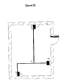
- FIG. 7A is an illustration of a collection of antennas connected by electric circuitry according to an embodiment of the present invention.
- FIG. 7B is an illustration of a collection of antennas with precise internal clocks according to an embodiment of the present invention.
- FIG. 7C is an illustration of a collection of direction-finding antennas according to an embodiment of the present invention.
- FIG. 7D is an illustration of a collection of antennas equipped with BluetoothTM interfaces according to an embodiment of the present invention.
- FIG. 7E is an illustration of a collection of antennas connected by ethernet to a central processing device according to an embodiment of the present invention.
- FIG. 8 illustrates a scenario of a prior art system transferring data using RFID technology.
- FIG. 9 illustrates the operation of a network security application according to an embodiment of the present invention.
- FIG. 10 is an illustration of an embodiment of a computer execution environment.
- FIG. 11 illustrates the operation of a network resource locator application according to an embodiment of the present invention.
- FIG. 12 illustrates the operation of a security application according to an embodiment of the present invention.
- the present invention is an apparatus and a method for the use of position information in wireless applications.
- numerous specific details are set forth to provide a more thorough description of embodiments of the invention. It will be apparent, however, to one skilled in the art, that the embodiments of the present invention may be practiced without these specific details. In other instances, well known features have not been described in detail so as not to obscure the invention
- Embodiments of the present invention are directed at gathering position information of mobile and stationary entities and using the position information in a wide variety of applications.
- Embodiments of the present invention use a plurality of signal transmitting devices and/or a plurality of signal gathering devices to gather position information of devices, objects and persons.
- Embodiments of the present invention use the position information gathered for security, tracking and other purposes.
- FIG. 1 illustrates a scenario where a signal gathering device is used to find position information of an entity needed by an end user application.
- An end user application can be an access control mechanism, a data bank, or any technology that needs location information.
- a signal gathering device is used to find the entity.
- the signal gathering device sends a signal.
- the signal transmitting device on the entity returns a signal to the signal gathering device indicating the presence of the entity.
- the signal gathering device calculates the position of the entity, and at block 160 this information is forwarded to the end user application.
- the signal gathering device sends the signal at a fixed time interval that is terminated after a clock-out time, and the results are forwarded to the end user application that needs the positioning information of the entity.
- the end user application can take appropriate steps. For example, if the end user application is an access control mechanism and the entity is the identification tag of an employee, then access is denied to the employee unless the tag is in range of the signal gathering device.
- the embodiment allows the end user application (in this case, the access control mechanism) to decide on a course of action based on the location information received. Therefore the possibility exists that access may still be denied to the employee for other reasons even if the employee tag is in range.
- existing wireless technology is leveraged to derive the location information of a mobile electronic device without modification to its components.
- this embodiment employs a signal gathering device to receive their signals for position calculation.
- a signal from a mobile electronic device which travels with a mobile user, can be used to locate the user or the device itself.
- this device is a cellular phone. In another embodiment, this device is a personal directory assistant (PDA). In another embodiment, this device is a device that employs radio signal (or infrared emanation) emitted by active devices like a BluetoothTM transmitter.
- PDA personal directory assistant
- this device is a device that employs radio signal (or infrared emanation) emitted by active devices like a BluetoothTM transmitter.
- the present invention is not limited to the three embodiments mentioned above, and can be used in other devices and technologies that use wireless transmission. Once the signal sensing device determines that a mobile user is present, it calculates its location and relays that information to other systems such as access control mechanisms, data banks, or end user applications.
- FIG. 2 illustrates a scenario whereby a signal from a mobile electronic device is used to pinpoint location of the device.
- the signal gathering device passively listens for signal.
- the signal gathering device is a collection of antennas.
- the signal can be radio signal or infrared emanation or any signal emitted by mobile electronic device. If a signal is heard at block 210 , then at block 220 signal gathering device calculates the location of the mobile electronic device.
- the location information can then be sent to the end user application. For example, the information can be used to update a location databank. If at block 210 no signal is heard, the signal gathering device goes back to passively listening for a signal.
- signal transmitting devices are added to existing objects or devices to allow for location calculation.
- the signal emitted by a signal transmitting device is collected by a signal gathering device to enable location calculation.
- a signal transmitting device is attached to a stationary object. For example, given an indoor space like a home, shop, library, or office, it may be necessary to pinpoint the location of a stationary entity like a phone, radio, television, computer, or VCR.
- a signal transmitting device can be attached to each of such entities.
- FIG. 3 illustrates a scenario where the location of one such entity mentioned above needs to be pinpointed.
- a signal (or query) is transmitted from a signal gathering device.
- the signal gathering device is a collection of antennas.
- the signal gathering device watches for a response to its query.
- a response signal is sent from the signal transmitting device to the signal gathering device at block 330 .
- location information of the entity is calculated and the result is used appropriately by an end user application at block 350 . If on the other hand, at block 320 , the signal gathering device does not get a response to the query sent, then at block 360 the signal gathering device concludes that the entity is either out of range or not present.
- the signal transmitting device is a Radio Frequency Identification (RFID) tag attached to the entity whose location information is needed.
- RFID Radio Frequency Identification
- the entity may be a non-animated object like a book in a library, an item like furniture, a gadget, an electronic item, a wireless LAN PCMCIA card, or an animated object like an employee of a company.
- RFID tags are also attached to mobile electronic devices that do not emit infrared or radio signals.
- a RFID tag is attached to an employee identification badge or other objects such as cellular phones and PDAs that are carried by the employee.
- FIG. 4 illustrates a scenario whereby a RFID tag is used to pinpoint location information of an entity.
- a signal (or query) is transmitted from a signal gathering device.
- the signal gathering device is a collection of antennas and one of the antennas is a transmitting antenna that sends the query.
- the signal gathering device watches for the response to the query from matching RFID tags within range.
- the query may be limited to a certain range of RFID (e.g. printers only vs. all devices). Thus other RFID tags may be in range and not respond to the query. If at block 420 a determination is made to see if a response (or responses) is received by the signal gathering device.
- the signal gathering device is a collection of antennas.
- An antenna can send a signal to query the presence of an entity.
- An antenna can also gather signals emitted from mobile electronic devices or from signal transmitting devices attached to entities.
- the signal gathering device is a collection of wall mounted antennas in an indoor space (e.g. an office, a home, a library, or a shop, etc). These wall mounted antennas, which may be flat wall mounted antennas, gather the response from a passive RFID tag attached to an entity, or a RFID transceiver attached to a book in a library, an employee ID badge, or a printer in an office, or from radio signals emitted from an active mobile electronic device such as a BluetoothTM transmitter.
- at least three wall mounted antennas are needed in order to pinpoint accurately the location of a signal transmitting device such as a RFID tag.
- FIG. 5 illustrates a scenario where a RFID transceiver attached to a printer in an office responds to a signal sent by a transmitting antenna.
- the transmitting antenna sends a query signal to locate a particular printer in an office.
- the printer responds to the query by sending a signal, which at block 520 is picked up by the wall mounted antennas in the office.
- the phase difference of the response or other timing information is gathered by each of the three wall mounted antennas.
- the common information received at the three wall mounted antennas is combined and the distance of the printer is calculated.
- this information is forwarded to other systems such as access control mechanisms, data banks, or end user applications to be used appropriately.
- FIG. 6 illustrates a plan view of a room 600 , containing a RFID transceiver 610 and three walled mounted antennas numbered 620 , 630 and 640 .
- a query signal is sent from antenna 620 , which is marked by a bold dotted line 650 .
- RFID transceiver 610 responds to the query signal, which is picked up by all 3 wall mounted antennas. This response is shown by a slim dotted line 660 .
- each antenna After calculating the phase difference or other timing information, each antenna sends its results, which are combined to calculate the exact position of RFID transceiver 610 . This information is forwarded to an end user application that uses the information appropriately.
- FIG. 7A shows one embodiment of the present invention in which all antennas within a given space are electrically connected to each other.
- Electric circuitry 704 connects antennas 701 , 702 and 703 and allows them to jointly figure out time delay and phase shift of incoming signal. The result indicates the position of the sender.
- FIG. 7B shows another embodiment that has each antenna carrying a very precise clock.
- Each antenna ( 711 , 712 and 713 ) uses its clock ( 715 , 716 , 717 ) to timestamp the incoming signal.
- the central processing device can then figure out where the RFID tags are located.
- the antennas need not to be connected by electric circuitry.
- FIG. 7C shows another embodiment of the present invention.
- the signal gathering device is a collection of passive antennas that have direction finding capabilities. Instead of having several antennas spaced far apart that need to be connected, a small cluster of direction finding antennas 731 , 732 and 733 are installed in the room. Each direction finding antenna generates angular information (in one plane). The information can then be combined to find the location of the signal sender such as RFID tag.
- FIG. 7D shows yet another embodiment in which the signal gathering device is a collection of RFID transceivers that are scattered in the room and bolted down at fixed locations.
- Each transceiver in the figure ( 741 , 742 and 743 ) is equipped with a BluetoothTM interface to access central processing device 745 .
- Each transceiver queries the room for RFID tags (or other signal senders) on its own and measures time delays of responses. By collecting time delays of several transceivers, the central processing device can then figure out where the RFID tags are located.
- FIG. 7E shows an embodiment of the present invention.
- RFID transceivers 751 , 752 and 753 are wired together to central processing device 755 via ethernet connection 754 .
- Each transceiver queries the room for RFID tags (or other signal senders) on its own and measures time delays of responses. By collecting time delays of several transceivers, the central processing device can then figure out where the RFID tags are located.
- Both embodiments in FIGS. 7D and 7E also allow for mobile electronic devices to be modified to query the transceivers in the room.
- each mobile electronic device will be able to perform its own location calculation and send the information to the central processing device.
- One way to perform the calculation would be for the mobile electronic device to ping each transceiver until a reply comes back. Then the mobile electronic device can gather the different replies and find its location. Since the calculation is delegated, the overhead costs of the position calculation can be reduced.
- the number of antennas and transceivers shown in FIGS. 7A-7E is for illustrative purpose only. Other embodiments may employ more or less antennas for a given indoor space.
- Embodiments of the present invention use the location information gathered for various applications.
- the location information is used to identify misplaced items such as misplaced books in the library.
- the location information of employee ID tags is used as additional authentication parameters to grant access and entry.
- the location information of wireless LAN PCMCIA ethernet cards can be used to allow or deny access to a corporate wireless network to deter hackers who are outside of the corporate building premise.
- FIG. 9 shows this embodiment.
- a RFID strip is attached to a wireless ethernet card.
- the mobile computer to which this ethernet card is attached attempts to find a base station so the computer can talk to the company internal wireless network. This is part of the IEEE 802.11 standard.
- a base station receives the request to connect to the network from the ethernet card. In prior art implementations, the base station would perform verification procedures.
- the base station connects to a location server and asks the location server for permission to connect the ethernet card at block 904 .
- the location server contains the ethernet address of the ethernet card and the RFID of its attached RFID strip.
- the location server then sends a query through the network of signal gathering devices (e.g. antennas) to detect the presence of the RFID strip at block 905 . If the RFID strip is found, then the location server can issue an authorization back to the base station at 906 .
- the base station starts accepting ethernet traffic from the ethernet card and relaying it onto the corporate wireless network, and vice versa. If the RFID strip attached to the ethernet card is not found, then the location server issues a denial at block 908 back to the base station. The base stations then issues an “access denied” message back to the ethernet card at block 909 .
- the location server may also have location information of all RFID tags that are currently visible to it. It may also have a database which correlates RFID serial numbers with identification data of the devices (e.g. the ethernet address of a wireless card) to which the RFID tags are attached. Thus, when an access point asks about a particular ethernet address, the location server knows to which RFID serial number this corresponds. After a query, it will make an access control decision, based on the position of the RFID tag (e.g. inside of the building vs. outside of the building).
- the location server can facilitate the location of resources on the wireless corporate network. Resources such as scanners and printers are equipped with ethernet card/RFID strip combination.
- the location server can direct the mobile computer user to the nearest resources on the wireless network based on the location of the ethernet card on the mobile computer.
- FIG. 11 shows this embodiment.
- a mobile computer user sends a “closest resource location query” to the base station via an ethernet card that has a RFID strip attached to it.
- the query can ask for the closest printer.
- the base station then forwards the ethernet card address of the mobile user and the query to the location server at block 1102 .
- the location server looks up the ethernet card address and finds its corresponding RFID.
- the location server uses the network of antennas to detect the present location of the ethernet card.
- it finds the closest resources to the mobile computer user by querying for all matching resources near the present location of the ethernet card.
- the location server already has a record of the location of all resources.
- the location server sends the query to the network of antennas.
- the RFID of the closest resource is found and the location server then looks up the ethernet address of the resource in reverse. Both the ethernet address and the location of the resource are sent back to the mobile computer user at block 1107 .
- the mobile computer can then use the ethernet address of the printer to send its print job and the user can use the location information of the printer to find the printer and pick up the print job.
- multiple matches may be returned to the mobile computer user.
- FIG. 12 shows a security application according to another embodiment of the present invention.
- the security application uses the location information to identify and react to unwanted displacement of equipment and property to prevent theft or vandalism.
- a RFID tag is attached to the entity in question.
- the entity carries sensitive information and must remain within a secured area.
- the boundaries of secured area and unsecured area are defined within the location server.
- a location server monitors the location of the entity by sending periodic queries. A detection of whether the entity is moved to an unsecured area (or out of range) is made at block 1204 . If it is, then the location server issues an alert at block 1205 .
- One or more embodiments of the present invention makes location positioning devices and/or location gathering devices using a general purpose computing environment such as environment 1000 illustrated in FIG. 10.
- a keyboard 1010 and mouse 1011 are coupled to a bi-directional system bus 1018 .
- the keyboard and mouse are for introducing user input to a computer 1001 and communicating that user input to processor 1013 .
- Computer 1001 may also include a communication interface 1020 coupled to bus 1018 .
- Communication interface 1020 provides a two-way data communication coupling via a network link 1021 to a local network 1022 .
- ISDN integrated services digital network
- communication interface 1020 provides a data communication connection to the corresponding type of telephone line, which comprises part of network link 1021 .
- LAN local area network
- communication interface 1020 provides a data communication connection via network link 1021 to a compatible LAN.
- Wireless links are also possible.
- communication interface 1020 sends and receives electrical, electromagnetic or optical signals, which carry digital data streams representing various types of information.
- Network link 1021 typically provides data communication through one or more networks to other data devices.
- network link 1021 may provide a connection through local network 1022 to local server computer 1023 or to data equipment operated by ISP 1024 .
- ISP 1024 in turn provides data communication services through the world wide packet data communication network now commonly referred to as the “Internet” 1025 .
- Internet 1025 uses electrical, electromagnetic or optical signals, which carry digital data streams.
- the signals through the various networks and the signals on network link 1021 and through communication interface 1020 which carry the digital data to and from computer 1000 , are exemplary forms of carrier waves transporting the information.
- Processor 1013 may reside wholly on client computer 1001 or wholly on server 1026 or processor 1013 may have its computational power distributed between computer 1001 and server 1026 .
- processor 1013 resides wholly on server 1026
- the results of the computations performed by processor 1013 are transmitted to computer 1001 via Internet 1025 , Internet Service Provider (ISP) 1024 , local network 1022 and communication interface 1020 .
- ISP Internet Service Provider
- computer 1001 is able to display the results of the computation to a user in the form of output.
- I/O (input/output) unit 1019 coupled to bidirectional system bus 1018 represents such I/O elements as a printer, A/V (audio/video) I/O, etc.
- Computer 1001 includes a video memory 1014 , main memory 1015 and mass storage 1012 , all coupled to bidirectional system bus 1018 along with keyboard 1010 , mouse 1011 and processor 1013 .
- main memory 1015 and mass storage 1012 can reside wholly on server 1026 or computer 1001 , or they may be distributed between the two. Examples of systems where processor 1013 , main memory 1015 , and mass storage 1012 are distributed between computer 1001 and server 1026 include the thin-client computing architecture developed by Sun Microsystems, Inc., the palm pilot computing device, Internet ready cellular phones, and other Internet computing devices.
- the mass storage 1012 may include both fixed and removable media, such as magnetic, optical or magnetic optical storage systems or any other available mass storage technology.
- Bus 1018 may contain, for example, thirty-two address lines for addressing video memory 1014 or main memory 1015 .
- the system bus 1018 also includes, for example, a 32-bit data bus for transferring data between and among the components, such as processor 1013 , main memory 1015 , video memory 1014 , and mass storage 1012 .
- multiplex data/address lines may be used instead of separate data and address lines.
- the processor 1013 is a microprocessor manufactured by Motorola, such as the 680 ⁇ 0 processor or a microprocessor manufactured by Intel, such as the 80 ⁇ 86 or Pentium processor, or a SPARC microprocessor from Sun Microsystems, Inc.
- Main memory 1015 is comprised of dynamic random access memory (DRAM).
- Video memory 1014 is a dual-ported video random access memory. One port of the video memory 1014 is coupled to video amplifier 1016 .
- the video amplifier 1016 is used to drive the cathode ray tube (CRT) raster monitor 1017 .
- Video amplifier 1016 is well known in the art and may be implemented by any suitable apparatus. This circuitry converts pixel data stored in video memory 1014 to a raster signal suitable for use by monitor 1017 .
- Monitor 1017 is a type of monitor suitable for displaying graphic images.
- Computer 1001 can send messages and receive data, including program code, through the network(s), network link 1021 , and communication interface 1020 .
- remote server computer 1026 might transmit a requested code for an application program through Internet 1025 , ISP 1024 , local network 1022 and communication interface 1020 .
- the received code may be executed by processor 1013 as it is received, and/or stored in mass storage 1012 , or other non-volatile storage for later execution.
- computer 1000 may obtain application code in the form of a carrier wave.
- remote server computer 1026 may execute applications using processor 1013 , and utilize mass storage 1012 , and/or video memory 1015 .
- the results of the execution at server 1026 are then transmitted through Internet 1025 , ISP 1024 , local network 1022 , and communication interface 1020 .
- computer 1001 performs only input and output functions.
- Application code may be embodied in any form of computer program product.
- a computer program product comprises a medium configured to store or transport computer readable code, or in which computer readable code may be embedded.
- Some examples of computer program products are CD-ROM disks, ROM cards, floppy disks, magnetic tapes, computer hard drives, servers on a network, and carrier waves.
Abstract
Description
Claims (6)
Priority Applications (1)
| Application Number | Priority Date | Filing Date | Title |
|---|---|---|---|
| US10/107,717 US6920330B2 (en) | 2002-03-26 | 2002-03-26 | Apparatus and method for the use of position information in wireless applications |
Applications Claiming Priority (1)
| Application Number | Priority Date | Filing Date | Title |
|---|---|---|---|
| US10/107,717 US6920330B2 (en) | 2002-03-26 | 2002-03-26 | Apparatus and method for the use of position information in wireless applications |
Publications (2)
| Publication Number | Publication Date |
|---|---|
| US20040203846A1 US20040203846A1 (en) | 2004-10-14 |
| US6920330B2 true US6920330B2 (en) | 2005-07-19 |
Family
ID=33129643
Family Applications (1)
| Application Number | Title | Priority Date | Filing Date |
|---|---|---|---|
| US10/107,717 Expired - Lifetime US6920330B2 (en) | 2002-03-26 | 2002-03-26 | Apparatus and method for the use of position information in wireless applications |
Country Status (1)
| Country | Link |
|---|---|
| US (1) | US6920330B2 (en) |
Cited By (112)
| Publication number | Priority date | Publication date | Assignee | Title |
|---|---|---|---|---|
| US20030206115A1 (en) * | 2002-05-01 | 2003-11-06 | John Krumm | Location measurement process for radio-frequency badges |
| US20040104809A1 (en) * | 2002-11-13 | 2004-06-03 | Stmicroelectronics S.A. | Communication between electromagnetic transponders |
| US20040116129A1 (en) * | 2002-12-13 | 2004-06-17 | Arlynn Wilson | System and method for controlling transceivers based on a location indicator |
| US20040133598A1 (en) * | 2003-01-08 | 2004-07-08 | Pat Dobrowski | Methods and apparatus for importing device data into a database system used in a process plant |
| US20060054691A1 (en) * | 2004-09-16 | 2006-03-16 | International Business Machines Corporation | Radio frequency identification (RFID) household system for tracking and managing RFID tag containing household possessions within short range RF limited boundaries of a household facility |
| US20060125631A1 (en) * | 2002-08-08 | 2006-06-15 | Jacob Sharony | RF tracking system and method |
| US7109986B2 (en) * | 2003-11-19 | 2006-09-19 | Eastman Kodak Company | Illumination apparatus |
| US20070060174A1 (en) * | 2005-09-15 | 2007-03-15 | Bellsouth Intellectual Property Corporation | Methods, systems, and computer program products for updating message routing profiles |
| US20070103303A1 (en) * | 2005-11-07 | 2007-05-10 | Radiofy Llc, A California Limited Liability Company | Wireless RFID networking systems and methods |
| US20070126634A1 (en) * | 2005-12-05 | 2007-06-07 | Honeywell International Inc. | Navigation system using radio frequency tags |
| US20070243851A1 (en) * | 2006-04-18 | 2007-10-18 | Radiofy Llc | Methods and systems for utilizing backscattering techniques in wireless applications |
| US20070248358A1 (en) * | 2006-04-19 | 2007-10-25 | Michael Sauer | Electrical-optical cable for wireless systems |
| US20070257796A1 (en) * | 2006-05-08 | 2007-11-08 | Easton Martyn N | Wireless picocellular RFID systems and methods |
| US20070269170A1 (en) * | 2006-05-19 | 2007-11-22 | Easton Martyn N | Fiber optic cable and fiber optic cable assembly for wireless access |
| US20070292136A1 (en) * | 2006-06-16 | 2007-12-20 | Michael Sauer | Transponder for a radio-over-fiber optical fiber cable |
| US20080001711A1 (en) * | 2006-06-15 | 2008-01-03 | Microsoft Corporation | Reliability of execution for device provider implementations |
| US20080001710A1 (en) * | 2006-06-15 | 2008-01-03 | Microsoft Corporation | Support for batching of events, and shredding of batched events in the rfid infrastructure platform |
| US20080044186A1 (en) * | 2006-08-16 | 2008-02-21 | Jacob George | Radio-over-fiber transponder with a dual-band patch antenna system |
| US20080070502A1 (en) * | 2006-09-15 | 2008-03-20 | Jacob George | Radio-over-fiber (RoF) optical fiber cable system with transponder diversity and RoF wireless picocellular system using same |
| US20080082258A1 (en) * | 2006-09-05 | 2008-04-03 | Honeywell International Inc. | Portable Positioning and Navigation System |
| US20080080863A1 (en) * | 2006-09-28 | 2008-04-03 | Michael Sauer | Radio-over-fiber (RoF) wireless picocellular system with combined picocells |
| US20080143584A1 (en) * | 2006-12-18 | 2008-06-19 | Radiofy Llc, A California Limited Liability Company | Method and system for determining the distance between an RFID reader and an RFID tag using phase |
| US20080143482A1 (en) * | 2006-12-18 | 2008-06-19 | Radiofy Llc, A California Limited Liability Company | RFID location systems and methods |
| US20080174404A1 (en) * | 2007-01-23 | 2008-07-24 | Microsoft Corporation | Dynamic updates in rfid manager |
| US20080184151A1 (en) * | 2007-01-25 | 2008-07-31 | Microsoft Corporation | Standardized mechanism for firmware upgrades of rfid devices |
| US20080186143A1 (en) * | 2007-02-06 | 2008-08-07 | Jacob George | Transponder systems and methods for radio-over-fiber (ROF) wireless picocellular systems |
| US20080231449A1 (en) * | 2007-03-20 | 2008-09-25 | Radiofy Llc | Method and apparatus for power management for a radio frequency identification system |
| US20080238686A1 (en) * | 2007-03-28 | 2008-10-02 | Micron Technology, Inc. | Methods and systems of determining physical characteristics associated with objects tagged with rfid tags |
| US20080238685A1 (en) * | 2007-03-28 | 2008-10-02 | Micron Technology, Inc. | Methods and systems of determining physical characteristics associated with objects tagged with rfid tags |
| US20080247343A1 (en) * | 2004-09-18 | 2008-10-09 | Stephan Lietz | Method for Requesting Information |
| US20080280560A1 (en) * | 2007-05-09 | 2008-11-13 | Micron Technology, Inc. | Method and system of placing a rfid tag in a continuous transmission mode |
| US20080278290A1 (en) * | 2005-05-03 | 2008-11-13 | Internatioanal Business Machines Corporation | Radio Frequency Identification (RFID) System for Dynamically and Automatically Establishing Communication Between A Mobile Wireless Communicating Device and A Processing System |
| US20080288625A1 (en) * | 2006-01-04 | 2008-11-20 | Microsoft Corporation | Rfid device groups |
| US20080297312A1 (en) * | 2007-05-30 | 2008-12-04 | Radiofy Llc | Systems and methods for providing quality of service to RFID |
| US20080307060A1 (en) * | 2007-03-28 | 2008-12-11 | Yusaku Okamura | Search system, management server, mobile communication device, search method, and program |
| US20080319653A1 (en) * | 2007-06-20 | 2008-12-25 | Radiofy Llc | Navigation system and methods for route navigation |
| US20080319652A1 (en) * | 2007-06-20 | 2008-12-25 | Radiofy Llc | Navigation system and methods for map navigation |
| US7492258B1 (en) | 2006-03-21 | 2009-02-17 | Radiofy Llc | Systems and methods for RFID security |
| US20090058638A1 (en) * | 2006-09-08 | 2009-03-05 | Symbol Technologies, Inc. | Methods and apparatus for a pervasive locationing and presence-detection system |
| US20090069972A1 (en) * | 2007-09-07 | 2009-03-12 | Maritz Inc. | Gps triggered narration and recording for drive events |
| US20090091428A1 (en) * | 2007-10-04 | 2009-04-09 | Keystone Technology Solutions, Llc | Method and System to Determine Physical Parameters as Between an RFID Tag and a Reader |
| US20090091454A1 (en) * | 2007-10-04 | 2009-04-09 | Micron Technology, Inc. | Method and System to Determine Physical Parameters as Between A RFID Tag and a Reader |
| US20090121927A1 (en) * | 2007-11-14 | 2009-05-14 | Radiofy Llc | Systems and Methods of Assisted GPS |
| US20090303004A1 (en) * | 2008-06-05 | 2009-12-10 | Keystone Technology Solutions, Llc | Systems and Methods to Determine Motion Parameters using RFID Tags |
| US20090303005A1 (en) * | 2008-06-05 | 2009-12-10 | Keystone Technology Solutions, Llc | Systems and Methods to Determine Kinematical Parameters using RFID Tags |
| US20100049615A1 (en) * | 2008-01-24 | 2010-02-25 | Qualcomm Incorporated | Mobile commerce authentication and authorization system |
| US20100052988A1 (en) * | 2008-08-27 | 2010-03-04 | Mstar Semiconductor, Inc. | Radio Frequency Positioning System and Method |
| US20100271263A1 (en) * | 2008-03-31 | 2010-10-28 | Mehran Moshfeghi | Method and System for Determining the Position of a Mobile Station |
| US20100309051A1 (en) * | 2008-03-31 | 2010-12-09 | Mehran Moshfeghi | Method and system for determining the position of a mobile device |
| US20100321246A1 (en) * | 2007-12-21 | 2010-12-23 | Amedo Smart Tracking Solutions Gmbh | Method for detecting motion |
| US20110043407A1 (en) * | 2008-03-31 | 2011-02-24 | GOLBA Radiofy LLC, a California Limited Liability Company | Methods and systems for determining the location of an electronic device |
| US7899621B2 (en) | 1997-10-22 | 2011-03-01 | Intelligent Technologies International, Inc. | Accident avoidance system |
| US20110060486A1 (en) * | 2009-09-09 | 2011-03-10 | General Electronics Corporation | Control system and method for remotely isolating powered units in a rail vehicle system |
| US20110156640A1 (en) * | 2009-12-25 | 2011-06-30 | Mehran Moshfeghi | Method and apparatus for wirelessly transferring power and communicating with one or more slave devices |
| US8010286B2 (en) | 2007-09-07 | 2011-08-30 | Maritz Inc. | Automated narration and recording for drive events |
| US8156539B1 (en) * | 2002-12-18 | 2012-04-10 | Cypress Semiconductor Corporation | Method and system for protecting a wireless network |
| US8175459B2 (en) | 2007-10-12 | 2012-05-08 | Corning Cable Systems Llc | Hybrid wireless/wired RoF transponder and hybrid RoF communication system using same |
| US8275265B2 (en) | 2010-02-15 | 2012-09-25 | Corning Cable Systems Llc | Dynamic cell bonding (DCB) for radio-over-fiber (RoF)-based networks and communication systems and related methods |
| US8548330B2 (en) | 2009-07-31 | 2013-10-01 | Corning Cable Systems Llc | Sectorization in distributed antenna systems, and related components and methods |
| US8644844B2 (en) | 2007-12-20 | 2014-02-04 | Corning Mobileaccess Ltd. | Extending outdoor location based services and applications into enclosed areas |
| US8830062B2 (en) | 2008-06-05 | 2014-09-09 | Micron Technology, Inc. | Systems and methods to use radar in RFID systems |
| US8831633B2 (en) | 2011-07-26 | 2014-09-09 | Golba Llc | Distributed method and system for calibrating the position of a mobile device |
| US8838477B2 (en) | 2011-06-09 | 2014-09-16 | Golba Llc | Method and system for communicating location of a mobile device for hands-free payment |
| US20140260424A1 (en) * | 2013-03-14 | 2014-09-18 | Michael K. Warren | Jewelry piece with interchangeable rfid tag |
| US8867919B2 (en) | 2007-07-24 | 2014-10-21 | Corning Cable Systems Llc | Multi-port accumulator for radio-over-fiber (RoF) wireless picocellular systems |
| US8873585B2 (en) | 2006-12-19 | 2014-10-28 | Corning Optical Communications Wireless Ltd | Distributed antenna system for MIMO technologies |
| US8965677B2 (en) | 1998-10-22 | 2015-02-24 | Intelligent Technologies International, Inc. | Intra-vehicle information conveyance system and method |
| US9037143B2 (en) | 2010-08-16 | 2015-05-19 | Corning Optical Communications LLC | Remote antenna clusters and related systems, components, and methods supporting digital data signal propagation between remote antenna units |
| US9042732B2 (en) | 2010-05-02 | 2015-05-26 | Corning Optical Communications LLC | Providing digital data services in optical fiber-based distributed radio frequency (RF) communication systems, and related components and methods |
| US9112611B2 (en) | 2009-02-03 | 2015-08-18 | Corning Optical Communications LLC | Optical fiber-based distributed antenna systems, components, and related methods for calibration thereof |
| US9178635B2 (en) | 2014-01-03 | 2015-11-03 | Corning Optical Communications Wireless Ltd | Separation of communication signal sub-bands in distributed antenna systems (DASs) to reduce interference |
| US9184843B2 (en) | 2011-04-29 | 2015-11-10 | Corning Optical Communications LLC | Determining propagation delay of communications in distributed antenna systems, and related components, systems, and methods |
| US9219879B2 (en) | 2009-11-13 | 2015-12-22 | Corning Optical Communications LLC | Radio-over-fiber (ROF) system for protocol-independent wired and/or wireless communication |
| US9240835B2 (en) | 2011-04-29 | 2016-01-19 | Corning Optical Communications LLC | Systems, methods, and devices for increasing radio frequency (RF) power in distributed antenna systems |
| US9247543B2 (en) | 2013-07-23 | 2016-01-26 | Corning Optical Communications Wireless Ltd | Monitoring non-supported wireless spectrum within coverage areas of distributed antenna systems (DASs) |
| US9258052B2 (en) | 2012-03-30 | 2016-02-09 | Corning Optical Communications LLC | Reducing location-dependent interference in distributed antenna systems operating in multiple-input, multiple-output (MIMO) configuration, and related components, systems, and methods |
| US9325429B2 (en) | 2011-02-21 | 2016-04-26 | Corning Optical Communications LLC | Providing digital data services as electrical signals and radio-frequency (RF) communications over optical fiber in distributed communications systems, and related components and methods |
| US9357551B2 (en) | 2014-05-30 | 2016-05-31 | Corning Optical Communications Wireless Ltd | Systems and methods for simultaneous sampling of serial digital data streams from multiple analog-to-digital converters (ADCS), including in distributed antenna systems |
| US9385810B2 (en) | 2013-09-30 | 2016-07-05 | Corning Optical Communications Wireless Ltd | Connection mapping in distributed communication systems |
| US9420542B2 (en) | 2014-09-25 | 2016-08-16 | Corning Optical Communications Wireless Ltd | System-wide uplink band gain control in a distributed antenna system (DAS), based on per band gain control of remote uplink paths in remote units |
| US9455784B2 (en) | 2012-10-31 | 2016-09-27 | Corning Optical Communications Wireless Ltd | Deployable wireless infrastructures and methods of deploying wireless infrastructures |
| US9525472B2 (en) | 2014-07-30 | 2016-12-20 | Corning Incorporated | Reducing location-dependent destructive interference in distributed antenna systems (DASS) operating in multiple-input, multiple-output (MIMO) configuration, and related components, systems, and methods |
| US9525488B2 (en) | 2010-05-02 | 2016-12-20 | Corning Optical Communications LLC | Digital data services and/or power distribution in optical fiber-based distributed communications systems providing digital data and radio frequency (RF) communications services, and related components and methods |
| US9531452B2 (en) | 2012-11-29 | 2016-12-27 | Corning Optical Communications LLC | Hybrid intra-cell / inter-cell remote unit antenna bonding in multiple-input, multiple-output (MIMO) distributed antenna systems (DASs) |
| US9602210B2 (en) | 2014-09-24 | 2017-03-21 | Corning Optical Communications Wireless Ltd | Flexible head-end chassis supporting automatic identification and interconnection of radio interface modules and optical interface modules in an optical fiber-based distributed antenna system (DAS) |
| US9621293B2 (en) | 2012-08-07 | 2017-04-11 | Corning Optical Communications Wireless Ltd | Distribution of time-division multiplexed (TDM) management services in a distributed antenna system, and related components, systems, and methods |
| US9647758B2 (en) | 2012-11-30 | 2017-05-09 | Corning Optical Communications Wireless Ltd | Cabling connectivity monitoring and verification |
| US9661781B2 (en) | 2013-07-31 | 2017-05-23 | Corning Optical Communications Wireless Ltd | Remote units for distributed communication systems and related installation methods and apparatuses |
| US9673904B2 (en) | 2009-02-03 | 2017-06-06 | Corning Optical Communications LLC | Optical fiber-based distributed antenna systems, components, and related methods for calibration thereof |
| US9681313B2 (en) | 2015-04-15 | 2017-06-13 | Corning Optical Communications Wireless Ltd | Optimizing remote antenna unit performance using an alternative data channel |
| US9715157B2 (en) | 2013-06-12 | 2017-07-25 | Corning Optical Communications Wireless Ltd | Voltage controlled optical directional coupler |
| US9730228B2 (en) | 2014-08-29 | 2017-08-08 | Corning Optical Communications Wireless Ltd | Individualized gain control of remote uplink band paths in a remote unit in a distributed antenna system (DAS), based on combined uplink power level in the remote unit |
| US9729267B2 (en) | 2014-12-11 | 2017-08-08 | Corning Optical Communications Wireless Ltd | Multiplexing two separate optical links with the same wavelength using asymmetric combining and splitting |
| US9749017B2 (en) | 2015-08-13 | 2017-08-29 | Golba Llc | Wireless charging system |
| US9775123B2 (en) | 2014-03-28 | 2017-09-26 | Corning Optical Communications Wireless Ltd. | Individualized gain control of uplink paths in remote units in a distributed antenna system (DAS) based on individual remote unit contribution to combined uplink power |
| US9807700B2 (en) | 2015-02-19 | 2017-10-31 | Corning Optical Communications Wireless Ltd | Offsetting unwanted downlink interference signals in an uplink path in a distributed antenna system (DAS) |
| US9812905B2 (en) | 2010-12-27 | 2017-11-07 | Golba Llc | Method and system for wireless battery charging utilizing ultrasonic transducer array based beamforming |
| US9829560B2 (en) | 2008-03-31 | 2017-11-28 | Golba Llc | Determining the position of a mobile device using the characteristics of received signals and a reference database |
| US9940663B2 (en) | 2013-08-15 | 2018-04-10 | Frank Daly Ward | Indoor location mapping and wayfinding system |
| US9948349B2 (en) | 2015-07-17 | 2018-04-17 | Corning Optical Communications Wireless Ltd | IOT automation and data collection system |
| US9974074B2 (en) | 2013-06-12 | 2018-05-15 | Corning Optical Communications Wireless Ltd | Time-division duplexing (TDD) in distributed communications systems, including distributed antenna systems (DASs) |
| US10014731B2 (en) | 2010-12-27 | 2018-07-03 | Golba Llc | Battery charging station for wireless battery charging |
| US10096909B2 (en) | 2014-11-03 | 2018-10-09 | Corning Optical Communications Wireless Ltd. | Multi-band monopole planar antennas configured to facilitate improved radio frequency (RF) isolation in multiple-input multiple-output (MIMO) antenna arrangement |
| US10110308B2 (en) | 2014-12-18 | 2018-10-23 | Corning Optical Communications Wireless Ltd | Digital interface modules (DIMs) for flexibly distributing digital and/or analog communications signals in wide-area analog distributed antenna systems (DASs) |
| US10128951B2 (en) | 2009-02-03 | 2018-11-13 | Corning Optical Communications LLC | Optical fiber-based distributed antenna systems, components, and related methods for monitoring and configuring thereof |
| US10135533B2 (en) | 2014-11-13 | 2018-11-20 | Corning Optical Communications Wireless Ltd | Analog distributed antenna systems (DASS) supporting distribution of digital communications signals interfaced from a digital signal source and analog radio frequency (RF) communications signals |
| US10136200B2 (en) | 2012-04-25 | 2018-11-20 | Corning Optical Communications LLC | Distributed antenna system architectures |
| US10187151B2 (en) | 2014-12-18 | 2019-01-22 | Corning Optical Communications Wireless Ltd | Digital-analog interface modules (DAIMs) for flexibly distributing digital and/or analog communications signals in wide-area analog distributed antenna systems (DASs) |
| US10236924B2 (en) | 2016-03-31 | 2019-03-19 | Corning Optical Communications Wireless Ltd | Reducing out-of-channel noise in a wireless distribution system (WDS) |
| US10560214B2 (en) | 2015-09-28 | 2020-02-11 | Corning Optical Communications LLC | Downlink and uplink communication path switching in a time-division duplex (TDD) distributed antenna system (DAS) |
| US10659163B2 (en) | 2014-09-25 | 2020-05-19 | Corning Optical Communications LLC | Supporting analog remote antenna units (RAUs) in digital distributed antenna systems (DASs) using analog RAU digital adaptors |
| US11178609B2 (en) | 2010-10-13 | 2021-11-16 | Corning Optical Communications LLC | Power management for remote antenna units in distributed antenna systems |
Families Citing this family (68)
| Publication number | Priority date | Publication date | Assignee | Title |
|---|---|---|---|---|
| US7403773B2 (en) * | 2002-06-27 | 2008-07-22 | Avaya Technology Corp. | Location-based access control for wireless local area networks |
| JP4062012B2 (en) * | 2002-08-21 | 2008-03-19 | 日本電気株式会社 | Mobile phone, advertisement distribution method used therefor, and program thereof |
| JP2004132890A (en) * | 2002-10-11 | 2004-04-30 | Fujitsu Component Ltd | Noncontact ic card reader/writer apparatus, noncontact ic card, input apparatus, and noncontact method for computing position of ic card |
| US20070132555A1 (en) * | 2005-02-14 | 2007-06-14 | Jason August | Ultra low frequency tag and system |
| US20050105600A1 (en) * | 2003-11-14 | 2005-05-19 | Okulus Networks Inc. | System and method for location tracking using wireless networks |
| EP1743137A4 (en) * | 2004-03-01 | 2008-06-25 | Ez 2 Cad Ltd | A system a method and an apparatus for performing wireless measurements, positioning and surface mapping by means of a portable coordinate system |
| US8522039B2 (en) * | 2004-06-09 | 2013-08-27 | Apple Inc. | Method and apparatus for establishing a federated identity using a personal wireless device |
| US7647024B2 (en) | 2005-10-03 | 2010-01-12 | Sellerbid, Inc. | Method and system for improving client server transmission over fading channel with wireless location and authentication technology via electromagnetic radiation |
| US7574732B2 (en) * | 2004-09-29 | 2009-08-11 | Symbol Technologies Inc | Object location based security using RFID |
| JP4431582B2 (en) * | 2004-12-07 | 2010-03-17 | シャープ株式会社 | Mobile phone |
| US20060136997A1 (en) * | 2004-12-21 | 2006-06-22 | Eastman Kodak Company | Authentication system and method |
| US8553153B2 (en) * | 2005-01-21 | 2013-10-08 | T.P. Vision Holding B.V. | Operation mode adjustment device and method of adjusting an operation mode of an electronic product |
| GB0507285D0 (en) * | 2005-04-11 | 2005-05-18 | Innovision Res & Tech Plc | Nfc enabled high-speed data |
| WO2006109032A1 (en) * | 2005-04-11 | 2006-10-19 | Innovision Research & Technology Plc | Communications apparatus |
| KR20080002863A (en) * | 2005-05-06 | 2008-01-04 | 오르소소프트 인코포레이티드 | Rf system for tracking objects |
| JP2009515232A (en) * | 2005-07-20 | 2009-04-09 | ベリマトリックス、インコーポレーテッド | Network user authentication system and method |
| US7839523B2 (en) * | 2005-12-13 | 2010-11-23 | Xerox Corporation | System and method for resolving a hardware identifier to a network address of networked device |
| US7688794B2 (en) * | 2005-12-13 | 2010-03-30 | Xerox Corporation | System and method for diverting a printing job to a proximal networked device |
| US7644295B1 (en) * | 2006-06-26 | 2010-01-05 | Rockwell Automation Technologies, Inc. | Powering a human machine interface by way of USB |
| US8326296B1 (en) | 2006-07-12 | 2012-12-04 | At&T Intellectual Property I, L.P. | Pico-cell extension for cellular network |
| US8468351B2 (en) * | 2006-12-15 | 2013-06-18 | Codesealer Aps | Digital data authentication |
| US9042905B2 (en) * | 2006-12-20 | 2015-05-26 | Rpx Clearinghouse Llc | Automatic configuration of telecommunication station sets |
| NZ578631A (en) * | 2007-01-22 | 2012-03-30 | Cellwitch Inc | System for monitoring of location of items comprising a plurality of wireless devices, a plurality of wireless communications systems and a processing system |
| ATE475940T1 (en) * | 2007-03-19 | 2010-08-15 | Simonsvoss Technologies Ag | LOW ENERGY DETECTION OF A TRANSPONDER THROUGH A READING UNIT AND SYSTEM FOR IDENTITY DETERMINATION OR/AND AUTHORIZATION DETERMINATION, IF APPLICABLE. IN THE FORM OF A LOCKING SYSTEM |
| US8626223B2 (en) | 2008-05-07 | 2014-01-07 | At&T Mobility Ii Llc | Femto cell signaling gating |
| US8719420B2 (en) | 2008-05-13 | 2014-05-06 | At&T Mobility Ii Llc | Administration of access lists for femtocell service |
| US8094551B2 (en) | 2008-05-13 | 2012-01-10 | At&T Mobility Ii Llc | Exchange of access control lists to manage femto cell coverage |
| US8743776B2 (en) | 2008-06-12 | 2014-06-03 | At&T Mobility Ii Llc | Point of sales and customer support for femtocell service and equipment |
| US8510801B2 (en) * | 2009-10-15 | 2013-08-13 | At&T Intellectual Property I, L.P. | Management of access to service in an access point |
| US11175375B2 (en) | 2010-11-12 | 2021-11-16 | Position Imaging, Inc. | Position tracking system and method using radio signals and inertial sensing |
| US10416276B2 (en) | 2010-11-12 | 2019-09-17 | Position Imaging, Inc. | Position tracking system and method using radio signals and inertial sensing |
| US9945940B2 (en) | 2011-11-10 | 2018-04-17 | Position Imaging, Inc. | Systems and methods of wireless position tracking |
| US10269182B2 (en) | 2012-06-14 | 2019-04-23 | Position Imaging, Inc. | RF tracking with active sensory feedback |
| US10180490B1 (en) | 2012-08-24 | 2019-01-15 | Position Imaging, Inc. | Radio frequency communication system |
| WO2014093961A1 (en) | 2012-12-15 | 2014-06-19 | Position Imaging, Inc | Cycling reference multiplexing receiver system |
| US9482741B1 (en) | 2013-01-18 | 2016-11-01 | Position Imaging, Inc. | System and method of locating a radio frequency (RF) tracking device using a calibration routine |
| US10856108B2 (en) | 2013-01-18 | 2020-12-01 | Position Imaging, Inc. | System and method of locating a radio frequency (RF) tracking device using a calibration routine |
| US9213873B2 (en) | 2013-03-22 | 2015-12-15 | Symbol Technologies, Llc | Determining movement of a radio frequency identification tag using a phase difference/frequency model |
| US10634761B2 (en) * | 2013-12-13 | 2020-04-28 | Position Imaging, Inc. | Tracking system with mobile reader |
| US9497728B2 (en) | 2014-01-17 | 2016-11-15 | Position Imaging, Inc. | Wireless relay station for radio frequency-based tracking system |
| US10200819B2 (en) | 2014-02-06 | 2019-02-05 | Position Imaging, Inc. | Virtual reality and augmented reality functionality for mobile devices |
| US20150256974A1 (en) * | 2014-03-06 | 2015-09-10 | Samsung Electronics Co., Ltd. | Proximity estimation method and apparatus using round trip time in a wireless communication system and method and apparatus for providing location based service using same |
| US10811908B2 (en) | 2014-09-25 | 2020-10-20 | Supply, Inc. | System and method for wireless power reception |
| US10090707B2 (en) | 2014-09-25 | 2018-10-02 | Supply, Inc. | Wireless power transmission |
| US10642560B2 (en) | 2015-02-13 | 2020-05-05 | Position Imaging, Inc. | Accurate geographic tracking of mobile devices |
| US10324474B2 (en) | 2015-02-13 | 2019-06-18 | Position Imaging, Inc. | Spatial diversity for relative position tracking |
| US11132004B2 (en) | 2015-02-13 | 2021-09-28 | Position Imaging, Inc. | Spatial diveristy for relative position tracking |
| US10148918B1 (en) | 2015-04-06 | 2018-12-04 | Position Imaging, Inc. | Modular shelving systems for package tracking |
| US11501244B1 (en) | 2015-04-06 | 2022-11-15 | Position Imaging, Inc. | Package tracking systems and methods |
| US11416805B1 (en) | 2015-04-06 | 2022-08-16 | Position Imaging, Inc. | Light-based guidance for package tracking systems |
| US10853757B1 (en) | 2015-04-06 | 2020-12-01 | Position Imaging, Inc. | Video for real-time confirmation in package tracking systems |
| US10444323B2 (en) | 2016-03-08 | 2019-10-15 | Position Imaging, Inc. | Expandable, decentralized position tracking systems and methods |
| US11436553B2 (en) | 2016-09-08 | 2022-09-06 | Position Imaging, Inc. | System and method of object tracking using weight confirmation |
| US10634503B2 (en) | 2016-12-12 | 2020-04-28 | Position Imaging, Inc. | System and method of personalized navigation inside a business enterprise |
| US10634506B2 (en) | 2016-12-12 | 2020-04-28 | Position Imaging, Inc. | System and method of personalized navigation inside a business enterprise |
| US10455364B2 (en) | 2016-12-12 | 2019-10-22 | Position Imaging, Inc. | System and method of personalized navigation inside a business enterprise |
| US11120392B2 (en) | 2017-01-06 | 2021-09-14 | Position Imaging, Inc. | System and method of calibrating a directional light source relative to a camera's field of view |
| CN110730992B (en) | 2017-06-06 | 2021-08-27 | 供应公司 | Method and system for wireless power transfer |
| US11178625B2 (en) | 2017-06-06 | 2021-11-16 | Supply, Inc. | Method and system for wireless power delivery |
| US10798665B2 (en) | 2017-06-06 | 2020-10-06 | Supply, Inc. | Method and system for wireless power delivery |
| US10424973B1 (en) | 2018-03-08 | 2019-09-24 | Supply, Inc. | Method and system for wireless power delivery |
| CN109190426A (en) * | 2018-07-30 | 2019-01-11 | 太原理工大学 | A kind of books based on RFID detect automatically and localization method |
| US11361536B2 (en) | 2018-09-21 | 2022-06-14 | Position Imaging, Inc. | Machine-learning-assisted self-improving object-identification system and method |
| WO2020113096A1 (en) | 2018-11-28 | 2020-06-04 | Supply, Inc. | System and method for wireless power delivery |
| WO2020113046A1 (en) | 2018-11-30 | 2020-06-04 | Supply, Inc. | Methods and systems for multi-objective optimization and/or wireless power delivery |
| WO2020146861A1 (en) | 2019-01-11 | 2020-07-16 | Position Imaging, Inc. | Computer-vision-based object tracking and guidance module |
| US10721603B1 (en) * | 2019-08-02 | 2020-07-21 | Nokia Solutions And Networks Oy | Managing network connectivity using network activity requests |
| US11611242B2 (en) | 2021-04-14 | 2023-03-21 | Reach Power, Inc. | System and method for wireless power networking |
Citations (14)
| Publication number | Priority date | Publication date | Assignee | Title |
|---|---|---|---|---|
| US5955994A (en) * | 1988-02-15 | 1999-09-21 | British Telecommunications Public Limited Company | Microstrip antenna |
| US6140964A (en) * | 1996-03-22 | 2000-10-31 | Matsushita Electric Industrial Co., Ltd. | Wireless communication system and method and system for detection of position of radio mobile station |
| US6222440B1 (en) * | 1998-02-23 | 2001-04-24 | Freshloc Technologies, Inc. | Location, identification and telemetry system using strobed signals at predetermined intervals |
| US6310576B1 (en) * | 1998-12-30 | 2001-10-30 | Motorola, Inc. | Method of identifying location using a master clock to synchronize time of arrival signals |
| US20020066030A1 (en) * | 2000-05-15 | 2002-05-30 | Brawn John Melvin | Secure network and method of establishing communication amongst network devices that have restricted network connectivity |
| US6414635B1 (en) * | 2000-10-23 | 2002-07-02 | Wayport, Inc. | Geographic-based communication service system with more precise determination of a user's known geographic location |
| US20020102995A1 (en) * | 1999-08-26 | 2002-08-01 | Intech 21, Inc. | Method for tracking the location of mobile units |
| US20030060212A1 (en) * | 2000-02-28 | 2003-03-27 | Invention Depot, Inc. | Method and system for location tracking |
| US20030225893A1 (en) * | 2002-03-01 | 2003-12-04 | Roese John J. | Locating devices in a data network |
| US6717516B2 (en) * | 2001-03-08 | 2004-04-06 | Symbol Technologies, Inc. | Hybrid bluetooth/RFID based real time location tracking |
| US6765484B2 (en) * | 2000-09-07 | 2004-07-20 | Savi Technology, Inc. | Method and apparatus for supplying commands to a tag |
| US20040147270A1 (en) * | 2002-12-31 | 2004-07-29 | Petrovich Adam M. | Identification scheme for a communication device |
| US6775616B1 (en) * | 1999-02-10 | 2004-08-10 | X-Cyte, Inc. | Environmental location system |
| US20040160323A1 (en) * | 2003-02-03 | 2004-08-19 | Stilp Louis A. | RFID transponder for a security system |
-
2002
- 2002-03-26 US US10/107,717 patent/US6920330B2/en not_active Expired - Lifetime
Patent Citations (14)
| Publication number | Priority date | Publication date | Assignee | Title |
|---|---|---|---|---|
| US5955994A (en) * | 1988-02-15 | 1999-09-21 | British Telecommunications Public Limited Company | Microstrip antenna |
| US6140964A (en) * | 1996-03-22 | 2000-10-31 | Matsushita Electric Industrial Co., Ltd. | Wireless communication system and method and system for detection of position of radio mobile station |
| US6222440B1 (en) * | 1998-02-23 | 2001-04-24 | Freshloc Technologies, Inc. | Location, identification and telemetry system using strobed signals at predetermined intervals |
| US6310576B1 (en) * | 1998-12-30 | 2001-10-30 | Motorola, Inc. | Method of identifying location using a master clock to synchronize time of arrival signals |
| US6775616B1 (en) * | 1999-02-10 | 2004-08-10 | X-Cyte, Inc. | Environmental location system |
| US20020102995A1 (en) * | 1999-08-26 | 2002-08-01 | Intech 21, Inc. | Method for tracking the location of mobile units |
| US20030060212A1 (en) * | 2000-02-28 | 2003-03-27 | Invention Depot, Inc. | Method and system for location tracking |
| US20020066030A1 (en) * | 2000-05-15 | 2002-05-30 | Brawn John Melvin | Secure network and method of establishing communication amongst network devices that have restricted network connectivity |
| US6765484B2 (en) * | 2000-09-07 | 2004-07-20 | Savi Technology, Inc. | Method and apparatus for supplying commands to a tag |
| US6414635B1 (en) * | 2000-10-23 | 2002-07-02 | Wayport, Inc. | Geographic-based communication service system with more precise determination of a user's known geographic location |
| US6717516B2 (en) * | 2001-03-08 | 2004-04-06 | Symbol Technologies, Inc. | Hybrid bluetooth/RFID based real time location tracking |
| US20030225893A1 (en) * | 2002-03-01 | 2003-12-04 | Roese John J. | Locating devices in a data network |
| US20040147270A1 (en) * | 2002-12-31 | 2004-07-29 | Petrovich Adam M. | Identification scheme for a communication device |
| US20040160323A1 (en) * | 2003-02-03 | 2004-08-19 | Stilp Louis A. | RFID transponder for a security system |
Cited By (252)
| Publication number | Priority date | Publication date | Assignee | Title |
|---|---|---|---|---|
| US7899621B2 (en) | 1997-10-22 | 2011-03-01 | Intelligent Technologies International, Inc. | Accident avoidance system |
| US8255144B2 (en) | 1997-10-22 | 2012-08-28 | Intelligent Technologies International, Inc. | Intra-vehicle information conveyance system and method |
| US8965677B2 (en) | 1998-10-22 | 2015-02-24 | Intelligent Technologies International, Inc. | Intra-vehicle information conveyance system and method |
| US20030206115A1 (en) * | 2002-05-01 | 2003-11-06 | John Krumm | Location measurement process for radio-frequency badges |
| US20050270170A1 (en) * | 2002-05-01 | 2005-12-08 | Microsoft Corporation | Location measurement process for radio-frequency badges |
| US6993592B2 (en) * | 2002-05-01 | 2006-01-31 | Microsoft Corporation | Location measurement process for radio-frequency badges |
| US7706809B2 (en) * | 2002-08-08 | 2010-04-27 | Symbol Technologies, Inc. | RF tracking system and method |
| US20060125631A1 (en) * | 2002-08-08 | 2006-06-15 | Jacob Sharony | RF tracking system and method |
| US20040104809A1 (en) * | 2002-11-13 | 2004-06-03 | Stmicroelectronics S.A. | Communication between electromagnetic transponders |
| US7308249B2 (en) * | 2002-11-13 | 2007-12-11 | Stmicroelectronics S.A. | Communication between electromagnetic transponders |
| US7471931B2 (en) * | 2002-12-13 | 2008-12-30 | Adtran, Inc. | System and method for controlling transceivers based on a location indicator |
| US20040116129A1 (en) * | 2002-12-13 | 2004-06-17 | Arlynn Wilson | System and method for controlling transceivers based on a location indicator |
| US8156539B1 (en) * | 2002-12-18 | 2012-04-10 | Cypress Semiconductor Corporation | Method and system for protecting a wireless network |
| US7152072B2 (en) * | 2003-01-08 | 2006-12-19 | Fisher-Rosemount Systems Inc. | Methods and apparatus for importing device data into a database system used in a process plant |
| US20040133598A1 (en) * | 2003-01-08 | 2004-07-08 | Pat Dobrowski | Methods and apparatus for importing device data into a database system used in a process plant |
| US7109986B2 (en) * | 2003-11-19 | 2006-09-19 | Eastman Kodak Company | Illumination apparatus |
| US7118037B2 (en) * | 2004-09-16 | 2006-10-10 | International Business Machines Corporation | Radio frequency identification (RFID) household system for tracking and managing RFID tag containing household possessions within short range RF limited boundaries of a household facility |
| US20060054691A1 (en) * | 2004-09-16 | 2006-03-16 | International Business Machines Corporation | Radio frequency identification (RFID) household system for tracking and managing RFID tag containing household possessions within short range RF limited boundaries of a household facility |
| US20080247343A1 (en) * | 2004-09-18 | 2008-10-09 | Stephan Lietz | Method for Requesting Information |
| US20080278290A1 (en) * | 2005-05-03 | 2008-11-13 | Internatioanal Business Machines Corporation | Radio Frequency Identification (RFID) System for Dynamically and Automatically Establishing Communication Between A Mobile Wireless Communicating Device and A Processing System |
| US7643797B2 (en) * | 2005-05-03 | 2010-01-05 | International Business Machines Corporation | Radio frequency identification (RFID) system for dynamically and automatically establishing communication between a mobile wireless communicating device and a data processing system |
| US20070060174A1 (en) * | 2005-09-15 | 2007-03-15 | Bellsouth Intellectual Property Corporation | Methods, systems, and computer program products for updating message routing profiles |
| US8107446B2 (en) | 2005-11-07 | 2012-01-31 | Radiofy Llc | Wireless RFID networking systems and methods |
| US10037445B2 (en) | 2005-11-07 | 2018-07-31 | Radiofy Llc | Systems and methods for managing coverage area of wireless communication devices |
| US20070103303A1 (en) * | 2005-11-07 | 2007-05-10 | Radiofy Llc, A California Limited Liability Company | Wireless RFID networking systems and methods |
| US8693455B2 (en) | 2005-11-07 | 2014-04-08 | Radiofy Llc | Wireless RFID networking systems and methods |
| US8345653B2 (en) | 2005-11-07 | 2013-01-01 | Radiofy Llc | Wireless RFID networking systems and methods |
| US7339523B2 (en) | 2005-12-05 | 2008-03-04 | Honeywell International Inc. | Navigation system using radio frequency tags |
| US20070126634A1 (en) * | 2005-12-05 | 2007-06-07 | Honeywell International Inc. | Navigation system using radio frequency tags |
| US20080288625A1 (en) * | 2006-01-04 | 2008-11-20 | Microsoft Corporation | Rfid device groups |
| US8452860B2 (en) | 2006-01-04 | 2013-05-28 | Microsoft Corporation | RFID device groups |
| US7492258B1 (en) | 2006-03-21 | 2009-02-17 | Radiofy Llc | Systems and methods for RFID security |
| US10164959B2 (en) | 2006-03-21 | 2018-12-25 | Radiofy Llc | Systems and methods for performing secure financial transactions |
| US8736424B2 (en) | 2006-03-21 | 2014-05-27 | Radiofy Llc | Systems and methods for performing secure financial transactions |
| US8325043B2 (en) | 2006-03-21 | 2012-12-04 | Radiofy Llc | Systems and methods for RFID security |
| US7952481B2 (en) | 2006-03-21 | 2011-05-31 | Radiofy Llc | Systems and methods for RFID security |
| US9628466B2 (en) | 2006-03-21 | 2017-04-18 | Radiofy Llc | Systems and methods for performing secure financial transactions |
| US9104926B2 (en) | 2006-03-21 | 2015-08-11 | Radiofy Llc | Systems and methods for performing secure financial transactions |
| US20100007466A1 (en) * | 2006-03-21 | 2010-01-14 | Radiofy Llc | Systems and methods for rfid security |
| US20110228941A1 (en) * | 2006-03-21 | 2011-09-22 | Radiofy LLC. | Systems and methods for rfid security |
| US8085149B2 (en) | 2006-03-21 | 2011-12-27 | Radiofy Llc | Systems and methods for RFID security |
| US20070243851A1 (en) * | 2006-04-18 | 2007-10-18 | Radiofy Llc | Methods and systems for utilizing backscattering techniques in wireless applications |
| US20100295663A1 (en) * | 2006-04-18 | 2010-11-25 | Radiofy Llc, A California Limited Liability Company | Methods and systems for utilizing backscattering techniques in wireless applications |
| US20070248358A1 (en) * | 2006-04-19 | 2007-10-25 | Michael Sauer | Electrical-optical cable for wireless systems |
| US7495560B2 (en) | 2006-05-08 | 2009-02-24 | Corning Cable Systems Llc | Wireless picocellular RFID systems and methods |
| US20070257796A1 (en) * | 2006-05-08 | 2007-11-08 | Easton Martyn N | Wireless picocellular RFID systems and methods |
| US20070269170A1 (en) * | 2006-05-19 | 2007-11-22 | Easton Martyn N | Fiber optic cable and fiber optic cable assembly for wireless access |
| US8472767B2 (en) | 2006-05-19 | 2013-06-25 | Corning Cable Systems Llc | Fiber optic cable and fiber optic cable assembly for wireless access |
| US8207822B2 (en) | 2006-06-15 | 2012-06-26 | Microsoft Corporation | Support for batching of events, and shredding of batched events in the RFID infrastructure platform |
| US20080001711A1 (en) * | 2006-06-15 | 2008-01-03 | Microsoft Corporation | Reliability of execution for device provider implementations |
| US20080001710A1 (en) * | 2006-06-15 | 2008-01-03 | Microsoft Corporation | Support for batching of events, and shredding of batched events in the rfid infrastructure platform |
| US20070292137A1 (en) * | 2006-06-16 | 2007-12-20 | Michael Sauer | Redundant transponder array for a radio-over-fiber optical fiber cable |
| US20070292136A1 (en) * | 2006-06-16 | 2007-12-20 | Michael Sauer | Transponder for a radio-over-fiber optical fiber cable |
| US20080044186A1 (en) * | 2006-08-16 | 2008-02-21 | Jacob George | Radio-over-fiber transponder with a dual-band patch antenna system |
| US7584048B2 (en) | 2006-09-05 | 2009-09-01 | Honeywell International Inc. | Portable positioning and navigation system |
| US20080082258A1 (en) * | 2006-09-05 | 2008-04-03 | Honeywell International Inc. | Portable Positioning and Navigation System |
| US20110109452A9 (en) * | 2006-09-08 | 2011-05-12 | Symbol Technologies, Inc. | Methods and apparatus for a pervasive locationing and presence-detection system |
| US7961098B2 (en) * | 2006-09-08 | 2011-06-14 | Symbol Technologies, Inc. | Methods and apparatus for a pervasive locationing and presence-detection system |
| US20090058638A1 (en) * | 2006-09-08 | 2009-03-05 | Symbol Technologies, Inc. | Methods and apparatus for a pervasive locationing and presence-detection system |
| US20080070502A1 (en) * | 2006-09-15 | 2008-03-20 | Jacob George | Radio-over-fiber (RoF) optical fiber cable system with transponder diversity and RoF wireless picocellular system using same |
| US7787823B2 (en) | 2006-09-15 | 2010-08-31 | Corning Cable Systems Llc | Radio-over-fiber (RoF) optical fiber cable system with transponder diversity and RoF wireless picocellular system using same |
| US7848654B2 (en) | 2006-09-28 | 2010-12-07 | Corning Cable Systems Llc | Radio-over-fiber (RoF) wireless picocellular system with combined picocells |
| US20080080863A1 (en) * | 2006-09-28 | 2008-04-03 | Michael Sauer | Radio-over-fiber (RoF) wireless picocellular system with combined picocells |
| US20080143584A1 (en) * | 2006-12-18 | 2008-06-19 | Radiofy Llc, A California Limited Liability Company | Method and system for determining the distance between an RFID reader and an RFID tag using phase |
| US8294554B2 (en) | 2006-12-18 | 2012-10-23 | Radiofy Llc | RFID location systems and methods |
| US20080143482A1 (en) * | 2006-12-18 | 2008-06-19 | Radiofy Llc, A California Limited Liability Company | RFID location systems and methods |
| US11921192B2 (en) | 2006-12-18 | 2024-03-05 | Innovo Surgical, Inc. | RFID location systems and methods |
| US8754752B2 (en) | 2006-12-18 | 2014-06-17 | Radiofy Llc | RFID location systems and methods |
| US10026073B2 (en) | 2006-12-18 | 2018-07-17 | Cria, Inc. | Method and system for communicating location of a mobile device for hands-free payment |
| US11009600B2 (en) | 2006-12-18 | 2021-05-18 | Innovo Surgical, Inc. | RFID location systems and methods |
| US9130613B2 (en) | 2006-12-19 | 2015-09-08 | Corning Optical Communications Wireless Ltd | Distributed antenna system for MIMO technologies |
| US8873585B2 (en) | 2006-12-19 | 2014-10-28 | Corning Optical Communications Wireless Ltd | Distributed antenna system for MIMO technologies |
| US20080174404A1 (en) * | 2007-01-23 | 2008-07-24 | Microsoft Corporation | Dynamic updates in rfid manager |
| US8245219B2 (en) | 2007-01-25 | 2012-08-14 | Microsoft Corporation | Standardized mechanism for firmware upgrades of RFID devices |
| US20080184151A1 (en) * | 2007-01-25 | 2008-07-31 | Microsoft Corporation | Standardized mechanism for firmware upgrades of rfid devices |
| US20080186143A1 (en) * | 2007-02-06 | 2008-08-07 | Jacob George | Transponder systems and methods for radio-over-fiber (ROF) wireless picocellular systems |
| US8111998B2 (en) | 2007-02-06 | 2012-02-07 | Corning Cable Systems Llc | Transponder systems and methods for radio-over-fiber (RoF) wireless picocellular systems |
| US8305190B2 (en) | 2007-03-20 | 2012-11-06 | Golba Llc | Method and apparatus for power management for a radio frequency identification system |
| US8629764B2 (en) | 2007-03-20 | 2014-01-14 | Golba Llc | Method and apparatus for power management for a radio frequency identification system |
| US8810372B2 (en) | 2007-03-20 | 2014-08-19 | Golba Llc | Method and apparatus for power management for a radio frequency identification system |
| US20080231449A1 (en) * | 2007-03-20 | 2008-09-25 | Radiofy Llc | Method and apparatus for power management for a radio frequency identification system |
| US7949743B2 (en) * | 2007-03-28 | 2011-05-24 | Nec Corporation | Search system, management server, mobile communication device, search method, and program |
| US20080238685A1 (en) * | 2007-03-28 | 2008-10-02 | Micron Technology, Inc. | Methods and systems of determining physical characteristics associated with objects tagged with rfid tags |
| US20080238686A1 (en) * | 2007-03-28 | 2008-10-02 | Micron Technology, Inc. | Methods and systems of determining physical characteristics associated with objects tagged with rfid tags |
| US7880618B2 (en) | 2007-03-28 | 2011-02-01 | Round Rock Research, Llc | Methods and systems of determining physical characteristics associated with objects tagged with RFID tags |
| US7859408B2 (en) | 2007-03-28 | 2010-12-28 | Round Rock Research, Llc | Methods and systems of determining physical characteristics associated with objects tagged with RFID tags |
| US20080307060A1 (en) * | 2007-03-28 | 2008-12-11 | Yusaku Okamura | Search system, management server, mobile communication device, search method, and program |
| US20080280560A1 (en) * | 2007-05-09 | 2008-11-13 | Micron Technology, Inc. | Method and system of placing a rfid tag in a continuous transmission mode |
| US8558673B2 (en) | 2007-05-30 | 2013-10-15 | Golba Llc | Systems and methods for providing quality of service to RFID |
| US9158947B2 (en) | 2007-05-30 | 2015-10-13 | Golba Llc | Mapping the determined RFID priority level of an RFID first network to a priority level corresponding to a second network to provide quality of service to RFID |
| US20080297312A1 (en) * | 2007-05-30 | 2008-12-04 | Radiofy Llc | Systems and methods for providing quality of service to RFID |
| US8284031B2 (en) | 2007-05-30 | 2012-10-09 | Golba Llc | Systems and methods for providing quality of service to RFID |
| US7978050B2 (en) | 2007-05-30 | 2011-07-12 | Golba Llc | Systems and methods for providing quality of service to RFID |
| US9729458B2 (en) | 2007-05-30 | 2017-08-08 | Golba Llc | Device for retrieving data from wireless devices based on mapping of read request priorities |
| US20080319653A1 (en) * | 2007-06-20 | 2008-12-25 | Radiofy Llc | Navigation system and methods for route navigation |
| US20080319652A1 (en) * | 2007-06-20 | 2008-12-25 | Radiofy Llc | Navigation system and methods for map navigation |
| US9360337B2 (en) | 2007-06-20 | 2016-06-07 | Golba Llc | Navigation system and methods for route navigation |
| US8867919B2 (en) | 2007-07-24 | 2014-10-21 | Corning Cable Systems Llc | Multi-port accumulator for radio-over-fiber (RoF) wireless picocellular systems |
| US8121784B2 (en) | 2007-09-07 | 2012-02-21 | Maritz, Inc. | GPS triggered narration and recording for drive events |
| US20090069972A1 (en) * | 2007-09-07 | 2009-03-12 | Maritz Inc. | Gps triggered narration and recording for drive events |
| US8010286B2 (en) | 2007-09-07 | 2011-08-30 | Maritz Inc. | Automated narration and recording for drive events |
| US20090091454A1 (en) * | 2007-10-04 | 2009-04-09 | Micron Technology, Inc. | Method and System to Determine Physical Parameters as Between A RFID Tag and a Reader |
| US20090091428A1 (en) * | 2007-10-04 | 2009-04-09 | Keystone Technology Solutions, Llc | Method and System to Determine Physical Parameters as Between an RFID Tag and a Reader |
| US7944356B2 (en) | 2007-10-04 | 2011-05-17 | Round Rock Research, Llc | Method and system to determine physical parameters as between an RFID tag and a reader |
| US7932814B2 (en) | 2007-10-04 | 2011-04-26 | Round Rock Research, Llc | Method and system to determine physical parameters as between a RFID tag and a reader |
| US8175459B2 (en) | 2007-10-12 | 2012-05-08 | Corning Cable Systems Llc | Hybrid wireless/wired RoF transponder and hybrid RoF communication system using same |
| US8718478B2 (en) | 2007-10-12 | 2014-05-06 | Corning Cable Systems Llc | Hybrid wireless/wired RoF transponder and hybrid RoF communication system using same |
| US8193978B2 (en) | 2007-11-14 | 2012-06-05 | Golba Llc | Positioning system and method using GPS with wireless access points |
| US20090121927A1 (en) * | 2007-11-14 | 2009-05-14 | Radiofy Llc | Systems and Methods of Assisted GPS |
| US9513375B2 (en) | 2007-11-14 | 2016-12-06 | Ip3, Series 100 Of Allied Security Trust I | Positioning system and method using GPS with wireless access points |
| US8644844B2 (en) | 2007-12-20 | 2014-02-04 | Corning Mobileaccess Ltd. | Extending outdoor location based services and applications into enclosed areas |
| US20100321246A1 (en) * | 2007-12-21 | 2010-12-23 | Amedo Smart Tracking Solutions Gmbh | Method for detecting motion |
| US8914302B2 (en) | 2008-01-24 | 2014-12-16 | Qualcomm Incorporated | Mobile commerce authentication and authorization system |
| US20100049615A1 (en) * | 2008-01-24 | 2010-02-25 | Qualcomm Incorporated | Mobile commerce authentication and authorization system |
| US20100309051A1 (en) * | 2008-03-31 | 2010-12-09 | Mehran Moshfeghi | Method and system for determining the position of a mobile device |
| US9366745B2 (en) | 2008-03-31 | 2016-06-14 | Golba Llc | Methods and systems for determining the location of an electronic device using multi-tone frequency signals |
| US9829560B2 (en) | 2008-03-31 | 2017-11-28 | Golba Llc | Determining the position of a mobile device using the characteristics of received signals and a reference database |
| US8754812B2 (en) | 2008-03-31 | 2014-06-17 | Golba Llc | Method and system for determining the location of an electronic device using multi-tone frequency signals |
| US9173187B2 (en) | 2008-03-31 | 2015-10-27 | Golba Llc | Determining the position of a mobile device using the characteristics of received signals and a reference database |
| US8344949B2 (en) | 2008-03-31 | 2013-01-01 | Golba Llc | Wireless positioning approach using time-delay of signals with a known transmission pattern |
| US9113343B2 (en) | 2008-03-31 | 2015-08-18 | Golba Llc | Wireless positioning approach using time-delay of signals with a known transmission pattern |
| US10073530B2 (en) | 2008-03-31 | 2018-09-11 | Golba Llc | Wireless positioning approach using time-delay of signals with a known transmission pattern |
| US8314736B2 (en) | 2008-03-31 | 2012-11-20 | Golba Llc | Determining the position of a mobile device using the characteristics of received signals and a reference database |
| US20110043407A1 (en) * | 2008-03-31 | 2011-02-24 | GOLBA Radiofy LLC, a California Limited Liability Company | Methods and systems for determining the location of an electronic device |
| US20100271263A1 (en) * | 2008-03-31 | 2010-10-28 | Mehran Moshfeghi | Method and System for Determining the Position of a Mobile Station |
| US8421676B2 (en) | 2008-03-31 | 2013-04-16 | Golba Llc | Method and system for determining the location of an electronic device using multi-tone frequency signals |
| US11403473B2 (en) | 2008-06-05 | 2022-08-02 | Micron Technology, Inc. | Systems and methods to determine kinematical parameters |
| US8242888B2 (en) | 2008-06-05 | 2012-08-14 | Keystone Technology Solutions, Llc | Systems and methods to determine motion parameters using RFID tags |
| US11237262B2 (en) | 2008-06-05 | 2022-02-01 | Micron Technology, Inc. | Systems and methods to use radar in RFID systems |
| US9030301B2 (en) | 2008-06-05 | 2015-05-12 | Micron Technology, Inc. | Systems and methods to determine kinematical parameters using RFID tags |
| US10592711B2 (en) | 2008-06-05 | 2020-03-17 | Micron Technology, Inc. | Systems and methods to determine kinematical parameters |
| US10650200B2 (en) | 2008-06-05 | 2020-05-12 | Micron Technology, Inc. | Systems and methods to determine motion parameters using RFID tags |
| US9477863B2 (en) | 2008-06-05 | 2016-10-25 | Micron Technology, Inc. | Systems and methods to determine motion parameters using RFID tags |
| US10162992B2 (en) | 2008-06-05 | 2018-12-25 | Micron Technology, Inc. | Systems and methods to determine kinematical parameters using RFID tags |
| US9690961B2 (en) | 2008-06-05 | 2017-06-27 | Micron Technology, Inc. | Systems and methods to determine kinematical parameters using RFID tags |
| US8461966B2 (en) | 2008-06-05 | 2013-06-11 | Micron Technology, Inc. | Systems and methods to determine kinematical parameters using RFID tags |
| US10571558B2 (en) | 2008-06-05 | 2020-02-25 | Micron Technology, Inc. | Systems and methods to use radar in RFID systems |
| US20090303004A1 (en) * | 2008-06-05 | 2009-12-10 | Keystone Technology Solutions, Llc | Systems and Methods to Determine Motion Parameters using RFID Tags |
| US8830062B2 (en) | 2008-06-05 | 2014-09-09 | Micron Technology, Inc. | Systems and methods to use radar in RFID systems |
| US10438031B2 (en) | 2008-06-05 | 2019-10-08 | Micron Technology, Inc. | Systems and methods to determine motion parameters using RFID tags |
| US8633805B2 (en) | 2008-06-05 | 2014-01-21 | Micron Technology, Inc. | Systems and methods to determine motion parameters using RFID tags |
| US11042720B2 (en) | 2008-06-05 | 2021-06-22 | Micron Technology, Inc. | Systems and methods to determine motion parameters using RFID tags |
| US20090303005A1 (en) * | 2008-06-05 | 2009-12-10 | Keystone Technology Solutions, Llc | Systems and Methods to Determine Kinematical Parameters using RFID Tags |
| US10824829B2 (en) | 2008-06-05 | 2020-11-03 | Micron Technology, Inc. | Systems and methods to determine kinematical parameters |
| US8193985B2 (en) * | 2008-08-27 | 2012-06-05 | Mstar Semiconductor, Inc. | Radio frequency positioning system and method |
| US20100052988A1 (en) * | 2008-08-27 | 2010-03-04 | Mstar Semiconductor, Inc. | Radio Frequency Positioning System and Method |
| US10128951B2 (en) | 2009-02-03 | 2018-11-13 | Corning Optical Communications LLC | Optical fiber-based distributed antenna systems, components, and related methods for monitoring and configuring thereof |
| US9900097B2 (en) | 2009-02-03 | 2018-02-20 | Corning Optical Communications LLC | Optical fiber-based distributed antenna systems, components, and related methods for calibration thereof |
| US9673904B2 (en) | 2009-02-03 | 2017-06-06 | Corning Optical Communications LLC | Optical fiber-based distributed antenna systems, components, and related methods for calibration thereof |
| US10153841B2 (en) | 2009-02-03 | 2018-12-11 | Corning Optical Communications LLC | Optical fiber-based distributed antenna systems, components, and related methods for calibration thereof |
| US9112611B2 (en) | 2009-02-03 | 2015-08-18 | Corning Optical Communications LLC | Optical fiber-based distributed antenna systems, components, and related methods for calibration thereof |
| US8548330B2 (en) | 2009-07-31 | 2013-10-01 | Corning Cable Systems Llc | Sectorization in distributed antenna systems, and related components and methods |
| US20110060486A1 (en) * | 2009-09-09 | 2011-03-10 | General Electronics Corporation | Control system and method for remotely isolating powered units in a rail vehicle system |
| US9729238B2 (en) | 2009-11-13 | 2017-08-08 | Corning Optical Communications LLC | Radio-over-fiber (ROF) system for protocol-independent wired and/or wireless communication |
| US9219879B2 (en) | 2009-11-13 | 2015-12-22 | Corning Optical Communications LLC | Radio-over-fiber (ROF) system for protocol-independent wired and/or wireless communication |
| US9485022B2 (en) | 2009-11-13 | 2016-11-01 | Corning Optical Communications LLC | Radio-over-fiber (ROF) system for protocol-independent wired and/or wireless communication |
| US8686685B2 (en) | 2009-12-25 | 2014-04-01 | Golba, Llc | Secure apparatus for wirelessly transferring power and communicating with one or more slave devices |
| US9847670B2 (en) | 2009-12-25 | 2017-12-19 | Golba Llc | Selective wireless charging of authorized slave devices |
| US20110156640A1 (en) * | 2009-12-25 | 2011-06-30 | Mehran Moshfeghi | Method and apparatus for wirelessly transferring power and communicating with one or more slave devices |
| US10014726B2 (en) | 2009-12-25 | 2018-07-03 | Golba Llc | Selective wireless charging of slave devices while limiting human exposure to RF beams |
| US8831428B2 (en) | 2010-02-15 | 2014-09-09 | Corning Optical Communications LLC | Dynamic cell bonding (DCB) for radio-over-fiber (RoF)-based networks and communication systems and related methods |
| US9319138B2 (en) | 2010-02-15 | 2016-04-19 | Corning Optical Communications LLC | Dynamic cell bonding (DCB) for radio-over-fiber (RoF)-based networks and communication systems and related methods |
| US8275265B2 (en) | 2010-02-15 | 2012-09-25 | Corning Cable Systems Llc | Dynamic cell bonding (DCB) for radio-over-fiber (RoF)-based networks and communication systems and related methods |
| US9853732B2 (en) | 2010-05-02 | 2017-12-26 | Corning Optical Communications LLC | Digital data services and/or power distribution in optical fiber-based distributed communications systems providing digital data and radio frequency (RF) communications services, and related components and methods |
| US9270374B2 (en) | 2010-05-02 | 2016-02-23 | Corning Optical Communications LLC | Providing digital data services in optical fiber-based distributed radio frequency (RF) communications systems, and related components and methods |
| US9525488B2 (en) | 2010-05-02 | 2016-12-20 | Corning Optical Communications LLC | Digital data services and/or power distribution in optical fiber-based distributed communications systems providing digital data and radio frequency (RF) communications services, and related components and methods |
| US9042732B2 (en) | 2010-05-02 | 2015-05-26 | Corning Optical Communications LLC | Providing digital data services in optical fiber-based distributed radio frequency (RF) communication systems, and related components and methods |
| US10014944B2 (en) | 2010-08-16 | 2018-07-03 | Corning Optical Communications LLC | Remote antenna clusters and related systems, components, and methods supporting digital data signal propagation between remote antenna units |
| US9037143B2 (en) | 2010-08-16 | 2015-05-19 | Corning Optical Communications LLC | Remote antenna clusters and related systems, components, and methods supporting digital data signal propagation between remote antenna units |
| US11671914B2 (en) | 2010-10-13 | 2023-06-06 | Corning Optical Communications LLC | Power management for remote antenna units in distributed antenna systems |
| US11224014B2 (en) | 2010-10-13 | 2022-01-11 | Corning Optical Communications LLC | Power management for remote antenna units in distributed antenna systems |
| US11212745B2 (en) | 2010-10-13 | 2021-12-28 | Corning Optical Communications LLC | Power management for remote antenna units in distributed antenna systems |
| US11178609B2 (en) | 2010-10-13 | 2021-11-16 | Corning Optical Communications LLC | Power management for remote antenna units in distributed antenna systems |
| US8913892B2 (en) | 2010-10-28 | 2014-12-16 | Coring Optical Communications LLC | Sectorization in distributed antenna systems, and related components and methods |
| US10014731B2 (en) | 2010-12-27 | 2018-07-03 | Golba Llc | Battery charging station for wireless battery charging |
| US9812905B2 (en) | 2010-12-27 | 2017-11-07 | Golba Llc | Method and system for wireless battery charging utilizing ultrasonic transducer array based beamforming |
| US9325429B2 (en) | 2011-02-21 | 2016-04-26 | Corning Optical Communications LLC | Providing digital data services as electrical signals and radio-frequency (RF) communications over optical fiber in distributed communications systems, and related components and methods |
| US10205538B2 (en) | 2011-02-21 | 2019-02-12 | Corning Optical Communications LLC | Providing digital data services as electrical signals and radio-frequency (RF) communications over optical fiber in distributed communications systems, and related components and methods |
| US9813164B2 (en) | 2011-02-21 | 2017-11-07 | Corning Optical Communications LLC | Providing digital data services as electrical signals and radio-frequency (RF) communications over optical fiber in distributed communications systems, and related components and methods |
| US9807722B2 (en) | 2011-04-29 | 2017-10-31 | Corning Optical Communications LLC | Determining propagation delay of communications in distributed antenna systems, and related components, systems, and methods |
| US10148347B2 (en) | 2011-04-29 | 2018-12-04 | Corning Optical Communications LLC | Systems, methods, and devices for increasing radio frequency (RF) power in distributed antenna systems |
| US9369222B2 (en) | 2011-04-29 | 2016-06-14 | Corning Optical Communications LLC | Determining propagation delay of communications in distributed antenna systems, and related components, systems, and methods |
| US9806797B2 (en) | 2011-04-29 | 2017-10-31 | Corning Optical Communications LLC | Systems, methods, and devices for increasing radio frequency (RF) power in distributed antenna systems |
| US9240835B2 (en) | 2011-04-29 | 2016-01-19 | Corning Optical Communications LLC | Systems, methods, and devices for increasing radio frequency (RF) power in distributed antenna systems |
| US9184843B2 (en) | 2011-04-29 | 2015-11-10 | Corning Optical Communications LLC | Determining propagation delay of communications in distributed antenna systems, and related components, systems, and methods |
| US8838477B2 (en) | 2011-06-09 | 2014-09-16 | Golba Llc | Method and system for communicating location of a mobile device for hands-free payment |
| US10467617B1 (en) | 2011-06-09 | 2019-11-05 | Cria, Inc. | Method and system for communicating location of a mobile device for hands-free payment |
| US9338606B2 (en) | 2011-07-26 | 2016-05-10 | Golba Llc | Distributed method and system for determining the position of a mobile device using long-range signals and calibrating the position using short-range signals |
| US8838135B2 (en) | 2011-07-26 | 2014-09-16 | Golba Llc | Distributed method and system for determining the position of a mobile device using long-range signals and calibrating the position using short-range signals |
| US9832602B2 (en) | 2011-07-26 | 2017-11-28 | Golba Llc | Distributed method and system for determining the position of a mobile device using long-range signals and calibrating the position using short-range signals |
| US8831633B2 (en) | 2011-07-26 | 2014-09-09 | Golba Llc | Distributed method and system for calibrating the position of a mobile device |
| US9843891B2 (en) | 2011-07-26 | 2017-12-12 | Golba Llc | Distributed method and system for calibrating the position of a mobile device |
| US9332394B2 (en) | 2011-07-26 | 2016-05-03 | Golba Llc | Distributed method and system for calibrating the position of a mobile device |
| US8838481B2 (en) | 2011-07-26 | 2014-09-16 | Golba Llc | Method and system for location based hands-free payment |
| US9258052B2 (en) | 2012-03-30 | 2016-02-09 | Corning Optical Communications LLC | Reducing location-dependent interference in distributed antenna systems operating in multiple-input, multiple-output (MIMO) configuration, and related components, systems, and methods |
| US9813127B2 (en) | 2012-03-30 | 2017-11-07 | Corning Optical Communications LLC | Reducing location-dependent interference in distributed antenna systems operating in multiple-input, multiple-output (MIMO) configuration, and related components, systems, and methods |
| US10349156B2 (en) | 2012-04-25 | 2019-07-09 | Corning Optical Communications LLC | Distributed antenna system architectures |
| US10136200B2 (en) | 2012-04-25 | 2018-11-20 | Corning Optical Communications LLC | Distributed antenna system architectures |
| US9621293B2 (en) | 2012-08-07 | 2017-04-11 | Corning Optical Communications Wireless Ltd | Distribution of time-division multiplexed (TDM) management services in a distributed antenna system, and related components, systems, and methods |
| US9973968B2 (en) | 2012-08-07 | 2018-05-15 | Corning Optical Communications Wireless Ltd | Distribution of time-division multiplexed (TDM) management services in a distributed antenna system, and related components, systems, and methods |
| US9455784B2 (en) | 2012-10-31 | 2016-09-27 | Corning Optical Communications Wireless Ltd | Deployable wireless infrastructures and methods of deploying wireless infrastructures |
| US9531452B2 (en) | 2012-11-29 | 2016-12-27 | Corning Optical Communications LLC | Hybrid intra-cell / inter-cell remote unit antenna bonding in multiple-input, multiple-output (MIMO) distributed antenna systems (DASs) |
| US9647758B2 (en) | 2012-11-30 | 2017-05-09 | Corning Optical Communications Wireless Ltd | Cabling connectivity monitoring and verification |
| US10361782B2 (en) | 2012-11-30 | 2019-07-23 | Corning Optical Communications LLC | Cabling connectivity monitoring and verification |
| US20140260424A1 (en) * | 2013-03-14 | 2014-09-18 | Michael K. Warren | Jewelry piece with interchangeable rfid tag |
| US9974074B2 (en) | 2013-06-12 | 2018-05-15 | Corning Optical Communications Wireless Ltd | Time-division duplexing (TDD) in distributed communications systems, including distributed antenna systems (DASs) |
| US9715157B2 (en) | 2013-06-12 | 2017-07-25 | Corning Optical Communications Wireless Ltd | Voltage controlled optical directional coupler |
| US11792776B2 (en) | 2013-06-12 | 2023-10-17 | Corning Optical Communications LLC | Time-division duplexing (TDD) in distributed communications systems, including distributed antenna systems (DASs) |
| US11291001B2 (en) | 2013-06-12 | 2022-03-29 | Corning Optical Communications LLC | Time-division duplexing (TDD) in distributed communications systems, including distributed antenna systems (DASs) |
| US9526020B2 (en) | 2013-07-23 | 2016-12-20 | Corning Optical Communications Wireless Ltd | Monitoring non-supported wireless spectrum within coverage areas of distributed antenna systems (DASs) |
| US9247543B2 (en) | 2013-07-23 | 2016-01-26 | Corning Optical Communications Wireless Ltd | Monitoring non-supported wireless spectrum within coverage areas of distributed antenna systems (DASs) |
| US9967754B2 (en) | 2013-07-23 | 2018-05-08 | Corning Optical Communications Wireless Ltd | Monitoring non-supported wireless spectrum within coverage areas of distributed antenna systems (DASs) |
| US10292056B2 (en) | 2013-07-23 | 2019-05-14 | Corning Optical Communications LLC | Monitoring non-supported wireless spectrum within coverage areas of distributed antenna systems (DASs) |
| US9661781B2 (en) | 2013-07-31 | 2017-05-23 | Corning Optical Communications Wireless Ltd | Remote units for distributed communication systems and related installation methods and apparatuses |
| US10664900B2 (en) | 2013-08-15 | 2020-05-26 | Frank Daly Ward | Indoor location mapping and wayfinding system |
| US11651419B2 (en) | 2013-08-15 | 2023-05-16 | Frank Ward | Indoor location mapping and wayfinding system |
| US9940663B2 (en) | 2013-08-15 | 2018-04-10 | Frank Daly Ward | Indoor location mapping and wayfinding system |
| US10679279B2 (en) | 2013-08-15 | 2020-06-09 | Frank Daly Ward | Indoor location mapping and wayfinding system |
| US10672063B2 (en) | 2013-08-15 | 2020-06-02 | Frank Daly Ward | Indoor location mapping and wayfinding system |
| US11182843B2 (en) | 2013-08-15 | 2021-11-23 | Frank Ward | Indoor location mapping and wayfinding system |
| US9385810B2 (en) | 2013-09-30 | 2016-07-05 | Corning Optical Communications Wireless Ltd | Connection mapping in distributed communication systems |
| US9178635B2 (en) | 2014-01-03 | 2015-11-03 | Corning Optical Communications Wireless Ltd | Separation of communication signal sub-bands in distributed antenna systems (DASs) to reduce interference |
| US9775123B2 (en) | 2014-03-28 | 2017-09-26 | Corning Optical Communications Wireless Ltd. | Individualized gain control of uplink paths in remote units in a distributed antenna system (DAS) based on individual remote unit contribution to combined uplink power |
| US9357551B2 (en) | 2014-05-30 | 2016-05-31 | Corning Optical Communications Wireless Ltd | Systems and methods for simultaneous sampling of serial digital data streams from multiple analog-to-digital converters (ADCS), including in distributed antenna systems |
| US9807772B2 (en) | 2014-05-30 | 2017-10-31 | Corning Optical Communications Wireless Ltd. | Systems and methods for simultaneous sampling of serial digital data streams from multiple analog-to-digital converters (ADCs), including in distributed antenna systems |
| US10256879B2 (en) | 2014-07-30 | 2019-04-09 | Corning Incorporated | Reducing location-dependent destructive interference in distributed antenna systems (DASS) operating in multiple-input, multiple-output (MIMO) configuration, and related components, systems, and methods |
| US9525472B2 (en) | 2014-07-30 | 2016-12-20 | Corning Incorporated | Reducing location-dependent destructive interference in distributed antenna systems (DASS) operating in multiple-input, multiple-output (MIMO) configuration, and related components, systems, and methods |
| US9929786B2 (en) | 2014-07-30 | 2018-03-27 | Corning Incorporated | Reducing location-dependent destructive interference in distributed antenna systems (DASS) operating in multiple-input, multiple-output (MIMO) configuration, and related components, systems, and methods |
| US9730228B2 (en) | 2014-08-29 | 2017-08-08 | Corning Optical Communications Wireless Ltd | Individualized gain control of remote uplink band paths in a remote unit in a distributed antenna system (DAS), based on combined uplink power level in the remote unit |
| US10397929B2 (en) | 2014-08-29 | 2019-08-27 | Corning Optical Communications LLC | Individualized gain control of remote uplink band paths in a remote unit in a distributed antenna system (DAS), based on combined uplink power level in the remote unit |
| US9602210B2 (en) | 2014-09-24 | 2017-03-21 | Corning Optical Communications Wireless Ltd | Flexible head-end chassis supporting automatic identification and interconnection of radio interface modules and optical interface modules in an optical fiber-based distributed antenna system (DAS) |
| US9929810B2 (en) | 2014-09-24 | 2018-03-27 | Corning Optical Communications Wireless Ltd | Flexible head-end chassis supporting automatic identification and interconnection of radio interface modules and optical interface modules in an optical fiber-based distributed antenna system (DAS) |
| US10659163B2 (en) | 2014-09-25 | 2020-05-19 | Corning Optical Communications LLC | Supporting analog remote antenna units (RAUs) in digital distributed antenna systems (DASs) using analog RAU digital adaptors |
| US9420542B2 (en) | 2014-09-25 | 2016-08-16 | Corning Optical Communications Wireless Ltd | System-wide uplink band gain control in a distributed antenna system (DAS), based on per band gain control of remote uplink paths in remote units |
| US9788279B2 (en) | 2014-09-25 | 2017-10-10 | Corning Optical Communications Wireless Ltd | System-wide uplink band gain control in a distributed antenna system (DAS), based on per-band gain control of remote uplink paths in remote units |
| US10096909B2 (en) | 2014-11-03 | 2018-10-09 | Corning Optical Communications Wireless Ltd. | Multi-band monopole planar antennas configured to facilitate improved radio frequency (RF) isolation in multiple-input multiple-output (MIMO) antenna arrangement |
| US10523326B2 (en) | 2014-11-13 | 2019-12-31 | Corning Optical Communications LLC | Analog distributed antenna systems (DASS) supporting distribution of digital communications signals interfaced from a digital signal source and analog radio frequency (RF) communications signals |
| US10135533B2 (en) | 2014-11-13 | 2018-11-20 | Corning Optical Communications Wireless Ltd | Analog distributed antenna systems (DASS) supporting distribution of digital communications signals interfaced from a digital signal source and analog radio frequency (RF) communications signals |
| US10135561B2 (en) | 2014-12-11 | 2018-11-20 | Corning Optical Communications Wireless Ltd | Multiplexing two separate optical links with the same wavelength using asymmetric combining and splitting |
| US9729267B2 (en) | 2014-12-11 | 2017-08-08 | Corning Optical Communications Wireless Ltd | Multiplexing two separate optical links with the same wavelength using asymmetric combining and splitting |
| US10361783B2 (en) | 2014-12-18 | 2019-07-23 | Corning Optical Communications LLC | Digital interface modules (DIMs) for flexibly distributing digital and/or analog communications signals in wide-area analog distributed antenna systems (DASs) |
| US10523327B2 (en) | 2014-12-18 | 2019-12-31 | Corning Optical Communications LLC | Digital-analog interface modules (DAIMs) for flexibly distributing digital and/or analog communications signals in wide-area analog distributed antenna systems (DASs) |
| US10110308B2 (en) | 2014-12-18 | 2018-10-23 | Corning Optical Communications Wireless Ltd | Digital interface modules (DIMs) for flexibly distributing digital and/or analog communications signals in wide-area analog distributed antenna systems (DASs) |
| US10187151B2 (en) | 2014-12-18 | 2019-01-22 | Corning Optical Communications Wireless Ltd | Digital-analog interface modules (DAIMs) for flexibly distributing digital and/or analog communications signals in wide-area analog distributed antenna systems (DASs) |
| US10292114B2 (en) | 2015-02-19 | 2019-05-14 | Corning Optical Communications LLC | Offsetting unwanted downlink interference signals in an uplink path in a distributed antenna system (DAS) |
| US9807700B2 (en) | 2015-02-19 | 2017-10-31 | Corning Optical Communications Wireless Ltd | Offsetting unwanted downlink interference signals in an uplink path in a distributed antenna system (DAS) |
| US10009094B2 (en) | 2015-04-15 | 2018-06-26 | Corning Optical Communications Wireless Ltd | Optimizing remote antenna unit performance using an alternative data channel |
| US9681313B2 (en) | 2015-04-15 | 2017-06-13 | Corning Optical Communications Wireless Ltd | Optimizing remote antenna unit performance using an alternative data channel |
| US9948349B2 (en) | 2015-07-17 | 2018-04-17 | Corning Optical Communications Wireless Ltd | IOT automation and data collection system |
| US9749017B2 (en) | 2015-08-13 | 2017-08-29 | Golba Llc | Wireless charging system |
| US10560214B2 (en) | 2015-09-28 | 2020-02-11 | Corning Optical Communications LLC | Downlink and uplink communication path switching in a time-division duplex (TDD) distributed antenna system (DAS) |
| US10236924B2 (en) | 2016-03-31 | 2019-03-19 | Corning Optical Communications Wireless Ltd | Reducing out-of-channel noise in a wireless distribution system (WDS) |
Also Published As
| Publication number | Publication date |
|---|---|
| US20040203846A1 (en) | 2004-10-14 |
Similar Documents
| Publication | Publication Date | Title |
|---|---|---|
| US6920330B2 (en) | Apparatus and method for the use of position information in wireless applications | |
| Indulska et al. | Location management in pervasive systems | |
| US7580995B2 (en) | Systems and methods for locating mobile computer users in a wireless network | |
| Spachos et al. | BLE beacons in the smart city: Applications, challenges, and research opportunities | |
| EP1398913B1 (en) | Using signal-generated location information to identify and list available devices | |
| US7433648B2 (en) | System and a node used in the system for wireless communication and sensory monitoring | |
| US6873258B2 (en) | Location aware services infrastructure | |
| CN101002450B (en) | Method, device and software for updating data in mobile devices | |
| KR100752823B1 (en) | Mobile devices including rfid tag readers | |
| US20010055976A1 (en) | Retrieval of location-related information | |
| US20120284066A1 (en) | Method and Apparatus for Geographic-Based Communications Service | |
| US20030130987A1 (en) | Relevance assessment for location information received from multiple sources | |
| CN101208974A (en) | Method for optimizing channel scanning function in telecommunication network of mobile terminal | |
| US6968181B2 (en) | Technique of providing information to mobile devices | |
| EP1866665A1 (en) | A system and method for searching physical objects | |
| Myllymaki et al. | Location aggregation from multiple sources | |
| EP1466275B1 (en) | A method for searching nodes for information | |
| EP2087745A1 (en) | Method and apparatus for mapping radio frequency identification (rfid) tags to network addresses | |
| CN1499855B (en) | Access point and method for connecting client-side and wide area network by the access point | |
| US20010029184A1 (en) | Monitoring of location-associated events | |
| KR20050075321A (en) | Information providing system and method using wireless data communication | |
| Siadat et al. | Location-based system for mobile devices using RFID | |
| JP2002523785A (en) | Data carrier locating system and method | |
| Callaghan et al. | Internal location based services using wireless sensor networks and RFID technology | |
| KR102648871B1 (en) | Apparatus and method for detecting and preventing abuse of location tracker |
Legal Events
| Date | Code | Title | Description |
|---|---|---|---|
| AS | Assignment |
Owner name: SUN MICROSYSTEMS, INC., CALIFORNIA Free format text: ASSIGNMENT OF ASSIGNORS INTEREST;ASSIGNORS:CARONNI, GERMANO;NYSTROM, ANN SOFIE;REEL/FRAME:012740/0003;SIGNING DATES FROM 20020320 TO 20020325 |
|
| STCF | Information on status: patent grant |
Free format text: PATENTED CASE |
|
| FPAY | Fee payment |
Year of fee payment: 4 |
|
| FPAY | Fee payment |
Year of fee payment: 8 |
|
| AS | Assignment |
Owner name: ORACLE AMERICA, INC., CALIFORNIA Free format text: MERGER AND CHANGE OF NAME;ASSIGNORS:ORACLE USA, INC.;SUN MICROSYSTEMS, INC.;ORACLE AMERICA, INC.;REEL/FRAME:037278/0853 Effective date: 20100212 |
|
| FPAY | Fee payment |
Year of fee payment: 12 |