US7087040B2 - Apparatus for delivering ablation fluid to treat lesions - Google Patents
Apparatus for delivering ablation fluid to treat lesions Download PDFInfo
- Publication number
- US7087040B2 US7087040B2 US10/074,468 US7446802A US7087040B2 US 7087040 B2 US7087040 B2 US 7087040B2 US 7446802 A US7446802 A US 7446802A US 7087040 B2 US7087040 B2 US 7087040B2
- Authority
- US
- United States
- Prior art keywords
- tines
- deployed position
- actuator
- elongated member
- housing
- Prior art date
- Legal status (The legal status is an assumption and is not a legal conclusion. Google has not performed a legal analysis and makes no representation as to the accuracy of the status listed.)
- Expired - Lifetime, expires
Links
Images


Classifications
-
- A—HUMAN NECESSITIES
- A61—MEDICAL OR VETERINARY SCIENCE; HYGIENE
- A61B—DIAGNOSIS; SURGERY; IDENTIFICATION
- A61B18/00—Surgical instruments, devices or methods for transferring non-mechanical forms of energy to or from the body
-
- A—HUMAN NECESSITIES
- A61—MEDICAL OR VETERINARY SCIENCE; HYGIENE
- A61B—DIAGNOSIS; SURGERY; IDENTIFICATION
- A61B17/00—Surgical instruments, devices or methods, e.g. tourniquets
- A61B2017/00831—Material properties
- A61B2017/00867—Material properties shape memory effect
-
- A—HUMAN NECESSITIES
- A61—MEDICAL OR VETERINARY SCIENCE; HYGIENE
- A61B—DIAGNOSIS; SURGERY; IDENTIFICATION
- A61B90/00—Instruments, implements or accessories specially adapted for surgery or diagnosis and not covered by any of the groups A61B1/00 - A61B50/00, e.g. for luxation treatment or for protecting wound edges
- A61B90/39—Markers, e.g. radio-opaque or breast lesions markers
- A61B2090/3937—Visible markers
-
- A—HUMAN NECESSITIES
- A61—MEDICAL OR VETERINARY SCIENCE; HYGIENE
- A61M—DEVICES FOR INTRODUCING MEDIA INTO, OR ONTO, THE BODY; DEVICES FOR TRANSDUCING BODY MEDIA OR FOR TAKING MEDIA FROM THE BODY; DEVICES FOR PRODUCING OR ENDING SLEEP OR STUPOR
- A61M25/00—Catheters; Hollow probes
- A61M25/0067—Catheters; Hollow probes characterised by the distal end, e.g. tips
- A61M25/0082—Catheter tip comprising a tool
- A61M25/0084—Catheter tip comprising a tool being one or more injection needles
- A61M2025/0085—Multiple injection needles protruding axially, i.e. along the longitudinal axis of the catheter, from the distal tip
-
- A—HUMAN NECESSITIES
- A61—MEDICAL OR VETERINARY SCIENCE; HYGIENE
- A61M—DEVICES FOR INTRODUCING MEDIA INTO, OR ONTO, THE BODY; DEVICES FOR TRANSDUCING BODY MEDIA OR FOR TAKING MEDIA FROM THE BODY; DEVICES FOR PRODUCING OR ENDING SLEEP OR STUPOR
- A61M25/00—Catheters; Hollow probes
- A61M25/0067—Catheters; Hollow probes characterised by the distal end, e.g. tips
- A61M25/0082—Catheter tip comprising a tool
- A61M2025/0096—Catheter tip comprising a tool being laterally outward extensions or tools, e.g. hooks or fibres
-
- A—HUMAN NECESSITIES
- A61—MEDICAL OR VETERINARY SCIENCE; HYGIENE
- A61M—DEVICES FOR INTRODUCING MEDIA INTO, OR ONTO, THE BODY; DEVICES FOR TRANSDUCING BODY MEDIA OR FOR TAKING MEDIA FROM THE BODY; DEVICES FOR PRODUCING OR ENDING SLEEP OR STUPOR
- A61M25/00—Catheters; Hollow probes
- A61M25/0067—Catheters; Hollow probes characterised by the distal end, e.g. tips
- A61M25/0068—Static characteristics of the catheter tip, e.g. shape, atraumatic tip, curved tip or tip structure
Definitions
- This application relates to a surgical apparatus for treating lesions and more particularly to an apparatus that delivers ablation fluid such as ethanol or acetic acid to ablate lesions.
- ablation fluid such as ethanol or acetic acid
- One current method of treating hepatic (liver) cellular carcinomas is using electrosurgical energy in the form of radiofrequency energy.
- a series of electrodes are placed in the malignant tumor and a generator is activated to apply energy to the electrodes which heats the tissue to destroy the tumor.
- a generator is activated to apply energy to the electrodes which heats the tissue to destroy the tumor.
- One example of such device is marketed by RITA Medical Systems which has an array of electrodes, offered in various configurations, which are curved outwardly from the tube in which they are constrained. It has been documented however in the literature that RF energy application is not consistently sufficient to ablate the cancerous tissue. Therefore, the patient must repeatedly return to the physician for additional applications of RF energy until the lesion is satisfactorily ablated.
- Another method of treating tumors is the injection of alcohol through a needle to ablate the tumor.
- the alcohol is typically about 95% to 99.5% ethanol and diffuses into the cancerous cells to produce immediate necrosis due to effects of cellular dehydration and protein denaturation followed by small vessel thrombosis.
- the needle is hollow and has two infusion ports adjacent the sharp distal tip.
- This device has several disadvantages.
- the ethanol is injected only adjacent the distal tip, creating a relatively small tumor treatment (ablation) zone. Therefore, the infusion needle must be repeatedly maneuvered and repositioned in various regions of the tumor and ethanol repeatedly injected until the entire region has been treated. In fact, oftentimes the needle will have to be fully removed and reinserted into the patient, sometimes as frequently as twenty times in a single surgical procedure thereby requiring twenty needle sticks, to ensure the entire region to be treated receives an adequate supply of ethanol.
- a fluid injection needle with a larger treatment zone capability to ablate a larger tumor. This would avoid multiple needle sticks, reduce the time required for treatment, and simplify the surgical procedure. A more uniform treatment zone would also be desirable. It would also be advantageous if the treatment zone can be varied so that the same delivery needle can be adapted for different sized lesions. Such injection needle could advantageously be used to inject acetic acid, ethanol or other ablation fluids.
- the present invention overcomes the problems and deficiencies of the prior art by advantageously.
- the present provides a surgical apparatus for delivering fluid to treat a lesion comprising a housing, a hollow elongated member extending from the housing, and a plurality of tines positioned in the elongated member. Each of the tines has a lumen and at least one opening communicating with the lumen for delivering fluid to the lesion.
- An actuator is operatively associated with the plurality of tines and is actuable to a first position to move the plurality of tines from a retracted position substantially within the elongated member to a first deployed position extending from the elongated member and is actuable to a second position to move the plurality of tines from the first position to a second deployed position extending further from the elongated member.
- the plurality of tines are preferably retained in the first and second deployed positions by retention structure.
- the actuator is movable in a first direction to move the tines from the retracted position to the first deployed position and movable in a second different direction to move the tines from the retracted position to the second deployed position so the tines are advanced further from the elongated member.
- the actuator is preferably rotatable and axially slidable to move the tines from the retracted position to the first deployed position and from the retracted position to the second deployed position.
- the elongated member preferably comprises a needle with a penetrating distal end.
- the housing includes a first and second track formed in an inside wall of the housing and the actuator includes a plunger having a first projecting surface slidably movable within the first track and a second projecting surface sidably movable within the second track.
- the plurality of tines are composed of shape memory metal wherein one of tines is extendable in substantial alignment with a longitudinal axis of the elongated member and at least two of the tines are extendable at an angle to the longitudinal axis of the elongated member, preferably up to about 90 degrees.
- the tines can alternatively be composed of stainless steel.
- the retention structure comprises a first detent located in the first track enagagable by the plunger to retain the tines in the first deployed position and a second detent located in the second track engagable by the plunger to retain the tines in the second deployed position.
- the present invention also provides a surgical apparatus for delivering fluid to treat a lesion comprising a housing, an elongated tissue penetrating member extending from the housing, and first and second tines positioned in the elongated member.
- Each of the tines has a lumen and at least one opening communicating with the lumen for delivering fluid to the lesion wherein the first and second tines are movable between a retracted position, a first deployed position and a second deployed position.
- the first tine is substantially aligned with a longitudinal axis of the elongated member in the retracted position and in the first deployed position
- the second tine is substantially aligned with a longitudinal axis of the elongated member in the retracted position and at an angle to the longitudinal axis of the elongated member in the first deployed position.
- An actuator is preferably provided which is rotatable in a first direction and axially slidable to move the first and second tines to the first deployed position and rotatable in a second direction and axially slidable to move the first and second tines to the second deployed position.
- the housing preferably includes a short track and a long track wherein the actuator is slidable in the short track to move the first and second tines to the first deployed position and slidable in the long track to move the first and second tines to the second deployed position.
- the actuator in the preferred embodiment comprises a plunger having a projecting surface slidably engagable within either the short or long track as the first and second tines are moved to the deployed positions.
- the present invention also provides an apparatus for delivering fluid to treat a lesion comprising a housing, an elongated member extending from the housing, a plurality of tines positioned in the elongated member, each having a lumen and at least one opening communicating with the lumen for delivering fluid to the lesion, and an actuator operatively associated with the tines.
- the actuator is actuable to a first position to move the plurality of tines from a retracted position substantially within the elongated member to a first deployed position extending distally of the elongated member and actuable to a second position to move the plurality of tines from the retracted position to a second deployed position extending distally of the elongated member, wherein the actuator is movable to the second position without movement to the first position.
- the present invention also provides an apparatus for delivering fluid to treat tumors comprising a housing, an elongated member extending from the housing, a plurality of tines positioned in the elongated member, each having a lumen and at least one opening communicating with the lumen for delivering fluid to the lesion, and a release mechanism operatively associated with the plurality of tines operable to release the plurality of tines from the elongated member to enable withdrawal from the apparatus.
- An actuator is operatively associated with the tines, the actuator actuable to move the plurality of tines from a first position substantially within the elongated member to a deployed position extending from the elongated member.
- An elongated support is preferably connected to the tines and connected to the actuator, wherein the elongated support and the actuator are removable with the tines from the elongated member and the housing.
- the housing may also include a release lever engagable with a tab extending from the actuator, the release lever biasing the tab out of engagement to enable release of the actuator.
- a collagen plug deployer is insertable into the elongated member after release and removal of the elongated support, actuator and plurality of tines.
- a method for treating a lesion comprising:
- FIG. 1 is a perspective view of the apparatus of the present invention in the initial position with the tines fully retracted within the needle;
- FIG. 2 is a perspective view of the apparatus of FIG. 1 with the tines in a first deployed position to define a first treatment zone;
- FIG. 3 is an enlarged perspective view of the distal portion of the apparatus of FIG. 2 showing the tines in the first deployed position;
- FIGS. 4 and 5 are enlarged perspective views (at different angles) of the distal portion of the apparatus of FIG. 1 showing the tines in a second deployed position to define a second treatment zone;
- FIG. 6 is an exploded view of the apparatus of FIG. 1 ;
- FIG. 6A is a perspective view of a three way stopcock
- FIG. 7 is an enlarged exploded view of the apparatus of FIG. 1 showing the housing halves for retaining the needle and needle sleeve;
- FIG. 8A is an enlarged perspective view of the second plunger half showing the engagement tab and projection
- FIG. 8B is a side view of the first housing half showing the tracks for receiving the engagement tab and projection of the first plunger half;
- FIG. 8C is a perspective view of the housing half of FIG. 8B ;
- FIG. 9A is a side view of the apparatus of FIG. 1 with the second housing half and the second plunger half removed to illustrate the position of the mounting tube and first plunger half when the apparatus is in the initial position with the tines retracted within the needle;
- FIG. 9B is a transverse cross-sectional view showing the interaction of the plunger and housing halves (the tines, tube and needle removed for clarity) when the apparatus is in the initial position of FIG. 1 ;
- FIG. 9C is a transverse cross-sectional view showing the interaction of the plunger and housing halves (the tines, tube and needle removed for clarity) when the apparatus is in the second (fully) deployed position;
- FIG. 10 is an enlarged side view illustrating the first plunger half in the initial position within the first housing half
- FIG. 11 is an enlarged front view of the apparatus in the initial position of FIG. 9A ;
- FIG. 12 is a side view of the apparatus with the second housing half and second plunger half removed to illustrate the position of the first plunger half when the apparatus is in the intermediate position with the tines partially deployed from the needle to a first deployed position;
- FIG. 13 is an enlarged front view of the apparatus in the intermediate position of FIG. 12 ;
- FIG. 14 is a side view of the apparatus with the second housing half and second plunger half removed to illustrate the position of the first plunger half when the apparatus is in the advanced position with the tines fully deployed from the needle to a second deployed position;
- FIG. 15 is an enlarged view of the proximal end of the apparatus of FIG. 14 showing the plunger knob rotated and linearly advanced for full deployment of the tines;
- FIG. 16 is an enlarged front view of the apparatus in the advanced position of FIG. 14 ;
- FIG. 17 is a perspective view of the proximal portion of the apparatus showing the plunger rotated and axially advanced to an intermediate position to deploy the tines to the first deployed position;
- FIG. 18 is a side view showing a first zone of treatment, depicted schematically by spherical zones, for the first deployed position of the tines;
- FIG. 19 is a perspective view of the proximal portion of the apparatus showing the plunger rotated and axially advanced to the advanced position to fully deploy the tines to the second deployed position;
- FIG. 20 is a side view showing a second zone of treatment, depicted schematically by spherical zones, for the second deployed position of the tines;
- FIG. 21 is an enlarged cross-sectional view showing the interaction of the release lever and finger to release the plunger to enable withdrawal of the tines, mounting tube and plunger from the needle and housing;
- FIG. 22 is a perspective view of the apparatus of FIG. 1 , with the second housing half removed to show the collagen plug deployer positioned within the apparatus.
- Apparatus 10 includes a housing or body 12 composed of housing halves 14 , 16 , an actuator 18 , and an elongated tubular member or needle 20 extending distally from the housing 12 .
- a plurality of tines which are extendable from the needle 20 in response to movement of the actuator 18 .
- the tines contain openings for delivery of the ablation fluid to the target tissue.
- Release levers 22 on housing 12 operate to release the tines from the apparatus 10 in the manner described below.
- FIG. 1 illustrates the tines in the retracted or non-deployed position with the actuator 18 in its initial (neutral) position.
- FIGS. 2 and 3 illustrate the tines, designated by reference numerals 24 a - 24 d , in a first deployed (or intermediate) position.
- actuator 18 which is in the form of a plunger with a knurled grip 47 , is rotated and slid axially in a distal direction towards the housing 12 . This advances tines 24 a - 24 d through the distal opening 33 of needle 20 , enabling the tines to extend angularly with respect to the longitudinal axis “a” of the needle 20 as shown.
- Each of the tines 24 a , 24 b , 24 c and 24 d has a respective penetrating tip 25 a - 25 d and a series of openings 26 for delivering fluid, e.g. ethanol or acetic acid, to the tissue.
- the beveled distal end 30 of needle 20 forms a cutting edge to facilitate passage of the apparatus 10 through the tissue when the tines 24 a - 24 d are in the retracted position.
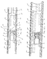
- FIGS. 4 and 5 illustrate the tines 24 a - 24 d in a second or fully deployed position.
- the actuator 18 has been rotated in the opposite direction to that of FIG. 2 and slid axially distally towards the housing 12 a greater distance than in FIG. 2 .
- This deploys the tines 24 a - 24 d further from the distal end 30 of the needle 20 , and at a greater angle to the longitudinal axis “a” of the needle 20 , providing a larger tissue treatment zone as will be described in detail below.
- Actuator or plunger 18 is composed of first and second halves 40 , 42 which are identical in configuration.
- Actuator or plunger half 40 has a proximal region 44 , which has a depression 46 cooperating with a corresponding depression formed in proximal region 43 of plunger (actuator) half 42 to form a mount for luer fitting 100 .
- Plunger half 42 has an engagement tab 48 formed on flexible finger 58 and a projection 50 spaced proximally from the engagement tab 48 , both extending outwardly from the outer surface and designed to engage a track in the first housing half 16 described below.
- Flexible finger 58 is formed by cutout 61 formed in plunger half 42 .
- Ledge 48 a ( FIG. 8A ) of tab 48 limits proximal movement of the plunger half 42 in the manner described below.
- plunger half 40 has an identical flexible finger having an engagement tab 55 and a projection 45 (shown in phantom) designed to travel in a track formed in second housing half 14 .
- first and second as used herein to describe the plunger and housing halves are solely for the purpose of clarity and convenience.
- mounting tube 70 mounted within plunger 18 is an elongated mounting tube 70 having an internal lumen extending along its length.
- the proximal end 75 of mounting tube 70 is connected to luer fitting 100 to enable fluid flow therethrough.
- Mounting tube 70 extends through the lumen of needle sleeve 90 and needle 20 , terminating adjacent the distal end 30 of needle 20 .
- Tines 24 a - 24 d are connected to mounting tube 70 by mounting pin 72 and mounting tube 70 is connected to plunger 18 by pin 74 . Consequently, rotation and axial movement (advancement/retraction) of plunger 18 rotates and moves the mounting tube 70 axially, which in turn rotates and moves the connected tines 24 a - 24 d axially.
- Mounting pin 72 is dimensioned so that its diameter is of sufficient size to prevent proximal movement of the tines in mounting tube 70 , but is less than the diameter of the internal lumen of mounting tube 70 . This enables ethanol (or other ablation fluid) to flow around the mounting pin 72 and through the tines 24 a - 24 d for delivery to the patient.
- housing 12 is composed of first and second housing halves 14 and 16 which are identical in configuration. Only housing half 14 will be described and identified with reference numerals, it being understood that housing half 16 has the identical structure.
- Housing half 14 has two sets of mounting ribs 80 , 82 which cooperate with identical ribs (not shown) on housing half 16 to frictionally engage and retain needle sleeve 90 and needle 20 , respectively. More specifically, needle sleeve 90 is seated within ribs 80 , has an axial opening 95 formed therethrough to accommodate fluid flow, and has a flat surface 92 to prevent rotation of the needle 20 within the housing 12 . Needle sleeve 90 terminates proximally of ribs 82 (see also FIG. 9A ) where distal opening 94 receives a proximal portion 23 of the needle 20 which can be bonded or attached thereto by any conventional means.
- Needle 20 extends between ribs 82 and exits through distal slot 84 , extending a sufficient distance distally of the distal ends 15 , 17 of housing halves 16 , 14 to enable access to the surgical site.
- the needle sleeve 92 and needle 90 are mounted within the ribs of housing half 16 in the identical manner.
- Each of the housing halves 14 , 16 has a distal track 51 and a proximal track 60 configured to receive the respective engagement tabs 48 , 55 and projections 50 , 45 of plunger halves 42 , 44 .
- the track is shown integrally formed on the inside wall of the housing halves, it is also contemplated that a separate component containing the desired track configuration can be mounted to the housing halves to provide the necessary engagement with the plunger tabs and projections.
- distal track 50 has a short track 52 and long track 54 with a pocket 66 formed in between; proximal track 60 has a long track 64 and a short track 62 joined by connector track 65 . Exit track 67 extends proximally from connector track 65 to enable removal of the plunger halves 42 , 44 in the manner described below.
- the identical track configuration is formed on housing half 16 and is therefore not shown or labeled.
- actuator 18 is positioned within housing 12 for both rotational and sliding movement therein. More specifically, engagement tab 55 rides in the distal track 51 and projection 45 rides in the proximal track 60 of housing half 14 . Similarly, engagement tab 48 and projection 50 travel in the respective distal and proximal tracks of housing half 16 .
- plunger 18 In the initial position of plunger 18 , projection 45 is seated in connector track 65 of track 60 and engagement tab 55 is seated in pocket 66 of track 51 with ledge 48 a abutting wall 25 preventing proximal movement thereof.
- engagement tab 55 rides over ramp 59 , and down ramp 58 into short track 52 , providing a tactile feel to the user that the plunger has been rotated so that the tab can engage short track 52 for movement of the tines to the first (intermediate) deployed position.
- This clockwise rotation of plunger 18 also moves projection 45 along transverse connector track 65 and in alignment with short track 62 . The plunger 18 is then pushed inwardly toward the housing 12 .
- the axial movement of the plunger 18 enables engagement tab 55 to travel distally within short track 52 and projection 45 to travel distally within short track 62 . Travel continues until the engagement tab 55 and projection 45 contact distal walls or stop 52 a and 62 a of short tracks 52 , 62 , respectively. Detent 52 b formed on short track 52 limits proximal movement of tab 55 in short track 52 a to prevent unwanted retraction of plunger 18 .
- This distal movement of plunger 18 advances mounting tube 70 distally with respect to needle 20 so tines 24 a - 24 d advance from the needle 20 to the first deployed (intermediate) position of FIGS. 12 and 13 .
- plunger 18 When plunger 18 is rotated counterclockwise from the neutral (initial) position, engagement tab 55 is moved from pocket 66 , over ramp 57 and down ramp 56 into long track 54 while projection 45 moves along connector track 65 into long track 64 .
- This movement over ramp 57 provides a tactile feel to the user that the plunger has been rotated.
- Plunger 18 is pushed distally and the tab 55 and projection 45 travel distally within long tracks 54 , 64 respectively, until contacting distal walls 54 a , 64 a which act as a stop to limit distal movement.
- This axial movement of plunger 18 moves mounting tube 70 distally a further distance than travel within short tracks 52 , 62 , causing ejection of the tines from needle 20 to a second or fully deployed position of FIGS.
- the tines 24 a - 24 d are at an angle of about 90 degrees with respect to the longitudinal axis of the elongated needle 20 , although other angles are also contemplated.
- detent 54 b in long track 54 restricts proximal movement of tab 55 , preventing unwanted retraction of plunger 18 .
- Detents 52 b and 54 b are preferably slightly angled to facilitate advancement of tabs 55 and 48 over the detents, but restrict retraction unless a sufficient force is applied.
- alignment surface 41 On knurled grip 47 is an alignment surface 41 which in cooperation with alignment seam 13 of housing 12 (see FIGS. 1 , 2 and 15 ) provides a visual indication to the user of the rotational position of the plunger 18 and therefore an indication of the position of the tines 24 a - 24 d . More specifically, in the first and second deployed positions, alignment surface 41 is out of alignment with alignment seam 13 of housing 12 (see e.g. FIG. 15 ), indicating to the user that the tines 24 a , 24 d are deployed.
- knurled grip 47 is spaced a distance or gap “g 1 ”, shown in FIG. 9A , from the proximal end of housing 12 .
- the distance between the proximal edge of housing 12 and the knurled grip 47 is defined by a smaller gap, namely gap g 2 .
- knurled grip 47 abuts the proximal edge of housing 12 . (see FIG. 15 )
- the apparatus 10 is inserted percutaneously through the skin to the target tissue site with the beveled edge 30 of needle 20 penetrating through tissue.
- the apparatus 10 is inserted with actuator 18 in the initial or neutral position so that tines 24 a - 24 are fully retracted inside needle 20 .
- the surgeon has the option to rotate the actuator 18 in a clockwise direction to create a first treatment zone or rotate the actuator in the opposite (counterclockwise) direction to create a second, larger treatment zone.
- actuator 18 is rotated clockwise and then pushed axially inwardly, with the engagement tabs and projection on the plunger halves riding in the short track portions of the distal and proximal tracks. This deploys the tines 24 a - 24 d to the position of FIGS. 2 and 3 with the tips 25 a - 25 d penetrating tissue. Note that alignment surface 41 is out of alignment with seam 13 , indicating to the user that the plunger has been moved from its neutral position.
- ethanol (or other ablation fluid) is injected through tube 108 of a conventional touhy borst 102 which is threadedly attached to luer fitting 100 , transported through the lumen 104 in luer fitting 100 and through mounting tube 70 and through the lumens in tines 24 a - 24 , exiting through holes 26 .
- a conventional touhy borst 102 which is threadedly attached to luer fitting 100 , transported through the lumen 104 in luer fitting 100 and through mounting tube 70 and through the lumens in tines 24 a - 24 , exiting through holes 26 .
- two holes are shown in each tine 24 , it is contemplated that one hole or more than two holes can be provided on various portions of one or more of the tines communicating with the internal lumen to achieve the desired effect.
- tine 24 d In this first deployed position, tine 24 d remains in a straight position substantially aligned with the longitudinal axis “a” of the needle 20 , and the other three tines 24 a , 24 b and 24 c extend outwardly at an angle to the longitudinal axis “a”, as they return to their memorized configuration to create a treatment zone Z 1 (FIG. 18 ).
- Tines 24 a - 24 d are preferably composed of shape memory metal, such as Nitinol, a nickel titanium alloy, which characteristically exhibits rigidity in the austenitic state and more flexibility in the martensitic state.
- the cold saline maintains the temperature dependent tines 24 a - 24 d in a relatively softer condition as they are in a martensitic state within needle 20 .
- 6A enables ethanol (or other ablation fluid such as acetic acid) to be inserted through tube 110 when stopcock 112 is in a first position, allows cold saline to be inserted through opening 114 when stopcock 112 is in a second position (rotated 90 degrees with respect to the first position), and prevents fluid flow when the stopcock is in the third position.
- ethanol or other ablation fluid such as acetic acid
- the portion of the lesion that is ablated by the ethanol is defined by the four intersecting spheres designated “Z 1 ”.
- the actuator 18 is rotated in a counterclockwise direction from its neutral position, and pushed inwardly so that tabs 48 , 55 and projections 50 , 45 of the plunger ride in the long track portions of the distal and proximal tracks 51 , 60 .
- This deploys the tines to the position of FIGS. 4 , 5 , and 16 as they are advanced from the needle 20 and exposed to warmer body temperature to return to their memorized configuration as they transition from the martensitic to the austenitic state.
- alignment surface 41 is out of alignment with seam 13 indicating that the actuator 18 has been rotated from its initial position.
- the tines 24 a - 24 c extend at a greater angle with respect to the longitudinal axis of the needle 20 and a greater angle with respect to the straight tine 24 d .
- four intersecting spherical areas FIG. 20 . As shown, these spheres occupy a larger area than the spheres of FIG. 18 to create a larger treatment zone Z 2 . Similar zones can be created with acetic acid or other ablation fluid.
- the user can rotate the entire apparatus, or reposition the apparatus 10 to apply ablation fluid to create an even larger treatment zone or to fill in the zone between the four spherical areas Z 1 or Z 2 .
- orientations can be reversed so that clockwise rotation moves the tabs into the larger track to create a larger treatment zone and counterclockwise rotation is designed to create a smaller treatment zone.
- a collagen plug This plug functions to fill the hole left in the ablated tissue, e.g. the liver, to fill the void to prevent bleeding or leaking.
- the apparatus 10 of the present invention can be utilized to insert the plug by removing the plunger 18 , mounting tube 70 and associated tines 24 a - 24 d , and inserting a collagen plug deployer such as deployer 200 illustrated in FIG. 22 . To release these components from the housing 12 , the release levers on housing halves 14 and 16 are depressed, thereby disengaging the engagement tabs 48 , 55 .
- release of only one of the tabs will be described, namely tab 48 of plunger half 42 , since tab 55 of plunger half 40 will be released by release lever 22 of housing half 14 in an identical manner.
- the bottom surface of release lever 22 has a cutout 22 a dimensioned to receive engagement tab 48 .
- Ledge 48 a of engagement tab 48 abuts wall 16 a of housing half 16 .
- tab 48 is forced downwardly to disengage ledge 48 a from wall 16 a , thereby freeing plunger half 42 for proximal movement in the direction of arrow “b” for withdrawal from the instrument.
- Projections 45 and 50 slide in their respective exit tracks, e.g. exit track 67 .
- Ramp 29 on plunger 42 provides a stop to limit downward movement of lever 22 .
- Collagen deployer 200 can be inserted into housing 12 .
- Collagen deployer 200 has an elongated tube extending from housing 202 which is inserted through needle sleeve 90 and needle 20 , terminating adjacent distal end 33 .
- a conventional cylindrically shaped collagen plug Positioned within the tube is a conventional cylindrically shaped collagen plug.
- a plunger is advanced towards the housing 202 , contacting the proximal end of the collagen plug and forcing it distally out of the elongated tube of the deployer 200 and exiting distal end 33 of needle 20 .
- a skin patch such as that shown in FIG. 25 of commonly assigned co-pending provisional patent application filed Nov. 7, 2001 under Express Mail No. ET715467283 (incorporated herein by reference in its entirety) can be provided with alignment markings, preferably spaced about 60 degrees apart.
- the skin patch is preferably mounted to the skin by adhesive and has an opening to allow passage of the apparatus therethrough.
- the apparatus can include an orientation arrow to provide a visual alignment indicator with the markings of skin patch. By orienting the arrow in alignment with the skin patch markings, the user can better control 60 degree (or other variations) rotational changes of the apparatus as the marking will indicate the radial orientation of the tines.
- the apparatus 10 and 300 of the present invention injects alcohol or acetic acid into the tumor to ablate the tumor.
- the alcohol is typically about 95% to 99.5% ethanol and diffuses into the cancerous cells, to produce immediate necrosis due to effects of cellular dehydration and protein denaturation followed by small vessel thrombosis.
- Acetic acid requires smaller volumes than ethanol to treat the lesion.
- Acetic acid diffuses into the cancerous cells, burning through the tumor septi, i.e. the compartments within the tumor, to produce immediate necrosis due to effects of cellular dehydration and protein denaturation followed by small vessel thrombosis.
- the volume of the fluid and the number of in infusions can vary.
- the apparatus 10 and 300 of the present invention can be used to deliver other fluids such as hot saline or acid to ablate the tissue.
- other fluids such as hot saline or acid
- the apparatus 10 and 300 can be utilized to treat tumors in other regions of the body such as the spleen, pancreas, or brain.
- the apparatus can also be used to inject other fluids, e.g. therapeutic fluids such as chemotherapeutic agents or gene cells.
Abstract
Description
Claims (10)
Priority Applications (2)
| Application Number | Priority Date | Filing Date | Title |
|---|---|---|---|
| US10/074,468 US7087040B2 (en) | 2001-02-28 | 2002-02-12 | Apparatus for delivering ablation fluid to treat lesions |
| US10/145,863 US6989004B2 (en) | 2001-02-28 | 2002-05-14 | Apparatus for delivering ablation fluid to treat lesions |
Applications Claiming Priority (2)
| Application Number | Priority Date | Filing Date | Title |
|---|---|---|---|
| US27211901P | 2001-02-28 | 2001-02-28 | |
| US10/074,468 US7087040B2 (en) | 2001-02-28 | 2002-02-12 | Apparatus for delivering ablation fluid to treat lesions |
Related Child Applications (2)
| Application Number | Title | Priority Date | Filing Date |
|---|---|---|---|
| US10/081,695 Continuation-In-Part US6905480B2 (en) | 2001-02-28 | 2002-02-22 | Apparatus for delivering ablation fluid to treat lesions |
| US10/145,863 Continuation-In-Part US6989004B2 (en) | 2001-02-28 | 2002-05-14 | Apparatus for delivering ablation fluid to treat lesions |
Publications (2)
| Publication Number | Publication Date |
|---|---|
| US20020120238A1 US20020120238A1 (en) | 2002-08-29 |
| US7087040B2 true US7087040B2 (en) | 2006-08-08 |
Family
ID=26755701
Family Applications (1)
| Application Number | Title | Priority Date | Filing Date |
|---|---|---|---|
| US10/074,468 Expired - Lifetime US7087040B2 (en) | 2001-02-28 | 2002-02-12 | Apparatus for delivering ablation fluid to treat lesions |
Country Status (1)
| Country | Link |
|---|---|
| US (1) | US7087040B2 (en) |
Cited By (87)
| Publication number | Priority date | Publication date | Assignee | Title |
|---|---|---|---|---|
| US20040147902A1 (en) * | 2001-02-28 | 2004-07-29 | Mcguckin James F. | Method for delivering ablation fluid to treat lesions |
| US20070142842A1 (en) * | 2005-11-18 | 2007-06-21 | Krueger John A | Device, system and method for delivering a curable material into bone |
| US20070185435A1 (en) * | 2004-11-15 | 2007-08-09 | Cytyc Corporation | Method and System for Drug Delivery |
| US20070270757A1 (en) * | 2006-05-17 | 2007-11-22 | Willis Geoffrey H | Needle array devices and methods |
| US20080015574A1 (en) * | 2006-03-31 | 2008-01-17 | Karpiel John A | Electrosurgical cutting device |
| US20090118673A1 (en) * | 2007-11-07 | 2009-05-07 | Jerett Creed | Needle injection catheter |
| US20090312617A1 (en) * | 2008-06-12 | 2009-12-17 | Jerett Creed | Needle injection catheter |
| US20100174267A1 (en) * | 1998-12-09 | 2010-07-08 | Rex Medical, Lp | Hollow curved superelastic medical needle and method |
| US20110160682A1 (en) * | 2008-01-31 | 2011-06-30 | Franano F Nicholas | Medical device |
| US20110202053A1 (en) * | 2010-02-16 | 2011-08-18 | Angiodynamics, Inc. | Ablation Device with Guide Sleeves |
| US8066713B2 (en) | 2003-03-31 | 2011-11-29 | Depuy Spine, Inc. | Remotely-activated vertebroplasty injection device |
| US8277506B2 (en) | 2008-06-24 | 2012-10-02 | Carefusion 2200, Inc. | Method and structure for stabilizing a vertebral body |
| US8298187B2 (en) | 2009-07-07 | 2012-10-30 | Cook Medical Technologies Llc | Fluid injection device |
| US20120323254A1 (en) * | 2011-06-20 | 2012-12-20 | Medtronic, Inc. | Medical assemblies and methods for implementation of multiple medical leads through a single entry |
| US8361078B2 (en) | 2003-06-17 | 2013-01-29 | Depuy Spine, Inc. | Methods, materials and apparatus for treating bone and other tissue |
| US8360629B2 (en) | 2005-11-22 | 2013-01-29 | Depuy Spine, Inc. | Mixing apparatus having central and planetary mixing elements |
| WO2013028781A1 (en) | 2011-08-24 | 2013-02-28 | Ablative Solutions, Inc. | Catheter system for vessel wall injection and perivascular renal denervation |
| US8415407B2 (en) | 2004-03-21 | 2013-04-09 | Depuy Spine, Inc. | Methods, materials, and apparatus for treating bone and other tissue |
| US8579908B2 (en) | 2003-09-26 | 2013-11-12 | DePuy Synthes Products, LLC. | Device for delivering viscous material |
| US8663190B2 (en) | 2011-04-22 | 2014-03-04 | Ablative Solutions, Inc. | Expandable catheter system for peri-ostial injection and muscle and nerve fiber ablation |
| US8690884B2 (en) | 2005-11-18 | 2014-04-08 | Carefusion 2200, Inc. | Multistate-curvature device and method for delivering a curable material into bone |
| WO2014070558A1 (en) | 2012-10-29 | 2014-05-08 | Ablative Solutions, Inc. | Peri-vascular tissue ablation catheter with support structures |
| US8950929B2 (en) | 2006-10-19 | 2015-02-10 | DePuy Synthes Products, LLC | Fluid delivery system |
| US8992541B2 (en) | 2003-03-14 | 2015-03-31 | DePuy Synthes Products, LLC | Hydraulic device for the injection of bone cement in percutaneous vertebroplasty |
| WO2015061614A1 (en) | 2013-10-25 | 2015-04-30 | Ablative Solutions, Inc. | Intravascular catheter with peri-vascular nerve activity sensors |
| US20150133850A1 (en) * | 2012-03-07 | 2015-05-14 | Stefan Tunev | Selective modulation of renal nerves |
| US9056185B2 (en) | 2011-08-24 | 2015-06-16 | Ablative Solutions, Inc. | Expandable catheter system for fluid injection into and deep to the wall of a blood vessel |
| US9168078B2 (en) | 2009-11-10 | 2015-10-27 | Carefusion 2200, Inc. | Apparatus and method for stylet-guided vertebral augmentation |
| US9179962B2 (en) | 2012-10-29 | 2015-11-10 | Ablative Solutions, Inc. | Transvascular methods of treating extravascular tissue |
| US9237925B2 (en) | 2011-04-22 | 2016-01-19 | Ablative Solutions, Inc. | Expandable catheter system for peri-ostial injection and muscle and nerve fiber ablation |
| US9254360B2 (en) | 2012-10-29 | 2016-02-09 | Ablative Solutions, Inc. | Peri-vascular tissue ablation catheter with deflection surface support structures |
| US9278196B2 (en) | 2011-08-24 | 2016-03-08 | Ablative Solutions, Inc. | Expandable catheter system for vessel wall injection and muscle and nerve fiber ablation |
| US9381024B2 (en) | 2005-07-31 | 2016-07-05 | DePuy Synthes Products, Inc. | Marked tools |
| US9554849B2 (en) | 2012-10-29 | 2017-01-31 | Ablative Solutions, Inc. | Transvascular method of treating hypertension |
| US9561068B2 (en) | 2008-10-06 | 2017-02-07 | Virender K. Sharma | Method and apparatus for tissue ablation |
| US9561066B2 (en) | 2008-10-06 | 2017-02-07 | Virender K. Sharma | Method and apparatus for tissue ablation |
| US9561067B2 (en) | 2008-10-06 | 2017-02-07 | Virender K. Sharma | Method and apparatus for tissue ablation |
| US9598691B2 (en) | 2008-04-29 | 2017-03-21 | Virginia Tech Intellectual Properties, Inc. | Irreversible electroporation to create tissue scaffolds |
| US9616204B2 (en) | 2012-03-02 | 2017-04-11 | Cook Medical Technologies LLC. | Dilation cap for endoluminal device |
| US9642932B2 (en) | 2006-09-14 | 2017-05-09 | DePuy Synthes Products, Inc. | Bone cement and methods of use thereof |
| US9700365B2 (en) | 2008-10-06 | 2017-07-11 | Santa Anna Tech Llc | Method and apparatus for the ablation of gastrointestinal tissue |
| US9757196B2 (en) | 2011-09-28 | 2017-09-12 | Angiodynamics, Inc. | Multiple treatment zone ablation probe |
| US9855402B2 (en) | 2014-02-15 | 2018-01-02 | Rex Medical, L.P. | Apparatus for delivering fluid to treat renal hypertension |
| US9867652B2 (en) | 2008-04-29 | 2018-01-16 | Virginia Tech Intellectual Properties, Inc. | Irreversible electroporation using tissue vasculature to treat aberrant cell masses or create tissue scaffolds |
| US9895189B2 (en) | 2009-06-19 | 2018-02-20 | Angiodynamics, Inc. | Methods of sterilization and treating infection using irreversible electroporation |
| US9918767B2 (en) | 2005-08-01 | 2018-03-20 | DePuy Synthes Products, Inc. | Temperature control system |
| US9931046B2 (en) | 2013-10-25 | 2018-04-03 | Ablative Solutions, Inc. | Intravascular catheter with peri-vascular nerve activity sensors |
| US9949652B2 (en) | 2013-10-25 | 2018-04-24 | Ablative Solutions, Inc. | Apparatus for effective ablation and nerve sensing associated with denervation |
| USRE46855E1 (en) | 2009-06-26 | 2018-05-22 | Orthovita, Inc. | K-wire and method for surgical procedures |
| USRE46872E1 (en) | 2009-06-26 | 2018-05-29 | Orthovita, Inc. | Guidewire and method for surgical procedures |
| US10064697B2 (en) | 2008-10-06 | 2018-09-04 | Santa Anna Tech Llc | Vapor based ablation system for treating various indications |
| US10117707B2 (en) | 2008-04-29 | 2018-11-06 | Virginia Tech Intellectual Properties, Inc. | System and method for estimating tissue heating of a target ablation zone for electrical-energy based therapies |
| US10154874B2 (en) | 2008-04-29 | 2018-12-18 | Virginia Tech Intellectual Properties, Inc. | Immunotherapeutic methods using irreversible electroporation |
| US10226278B2 (en) | 2012-10-29 | 2019-03-12 | Ablative Solutions, Inc. | Method for painless renal denervation using a peri-vascular tissue ablation catheter with support structures |
| US10238447B2 (en) | 2008-04-29 | 2019-03-26 | Virginia Tech Intellectual Properties, Inc. | System and method for ablating a tissue site by electroporation with real-time monitoring of treatment progress |
| US10245105B2 (en) | 2008-04-29 | 2019-04-02 | Virginia Tech Intellectual Properties, Inc. | Electroporation with cooling to treat tissue |
| US10272178B2 (en) | 2008-04-29 | 2019-04-30 | Virginia Tech Intellectual Properties Inc. | Methods for blood-brain barrier disruption using electrical energy |
| US10292755B2 (en) | 2009-04-09 | 2019-05-21 | Virginia Tech Intellectual Properties, Inc. | High frequency electroporation for cancer therapy |
| WO2019195625A1 (en) | 2018-04-06 | 2019-10-10 | Ablative Solutions, Inc. | Peri-vascular tissue ablation catheters |
| US10471254B2 (en) | 2014-05-12 | 2019-11-12 | Virginia Tech Intellectual Properties, Inc. | Selective modulation of intracellular effects of cells using pulsed electric fields |
| US10470822B2 (en) | 2008-04-29 | 2019-11-12 | Virginia Tech Intellectual Properties, Inc. | System and method for estimating a treatment volume for administering electrical-energy based therapies |
| WO2019232378A1 (en) * | 2018-06-01 | 2019-12-05 | Presage Biosciences, Inc. | Low-profile multi-agent injection system and methods |
| US10517666B2 (en) | 2013-10-25 | 2019-12-31 | Ablative Solutions, Inc. | Apparatus for effective ablation and nerve sensing associated with denervation |
| US10568693B2 (en) | 2016-12-16 | 2020-02-25 | Nanospectra Biosciences, Inc. | Devices and the use thereof in methods for ablation therapy |
| US10695126B2 (en) | 2008-10-06 | 2020-06-30 | Santa Anna Tech Llc | Catheter with a double balloon structure to generate and apply a heated ablative zone to tissue |
| US10694972B2 (en) | 2014-12-15 | 2020-06-30 | Virginia Tech Intellectual Properties, Inc. | Devices, systems, and methods for real-time monitoring of electrophysical effects during tissue treatment |
| US10702326B2 (en) | 2011-07-15 | 2020-07-07 | Virginia Tech Intellectual Properties, Inc. | Device and method for electroporation based treatment of stenosis of a tubular body part |
| US10736656B2 (en) | 2012-10-29 | 2020-08-11 | Ablative Solutions | Method for painless renal denervation using a peri-vascular tissue ablation catheter with support structures |
| US10849685B2 (en) | 2018-07-18 | 2020-12-01 | Ablative Solutions, Inc. | Peri-vascular tissue access catheter with locking handle |
| US10869996B2 (en) | 2016-10-29 | 2020-12-22 | Stephen Kuperberg | Method and apparatus for sequential deployment of intra-tumoral agents |
| US10881458B2 (en) | 2012-10-29 | 2021-01-05 | Ablative Solutions, Inc. | Peri-vascular tissue ablation catheters |
| US10945787B2 (en) | 2012-10-29 | 2021-03-16 | Ablative Solutions, Inc. | Peri-vascular tissue ablation catheters |
| US10960176B2 (en) | 2014-12-19 | 2021-03-30 | Hospital For Special Surgery | Multi-catheter infusion system and method thereof |
| US11254926B2 (en) | 2008-04-29 | 2022-02-22 | Virginia Tech Intellectual Properties, Inc. | Devices and methods for high frequency electroporation |
| US11272979B2 (en) | 2008-04-29 | 2022-03-15 | Virginia Tech Intellectual Properties, Inc. | System and method for estimating tissue heating of a target ablation zone for electrical-energy based therapies |
| US11311329B2 (en) | 2018-03-13 | 2022-04-26 | Virginia Tech Intellectual Properties, Inc. | Treatment planning for immunotherapy based treatments using non-thermal ablation techniques |
| US11331140B2 (en) | 2016-05-19 | 2022-05-17 | Aqua Heart, Inc. | Heated vapor ablation systems and methods for treating cardiac conditions |
| US11382681B2 (en) | 2009-04-09 | 2022-07-12 | Virginia Tech Intellectual Properties, Inc. | Device and methods for delivery of high frequency electrical pulses for non-thermal ablation |
| US11453873B2 (en) | 2008-04-29 | 2022-09-27 | Virginia Tech Intellectual Properties, Inc. | Methods for delivery of biphasic electrical pulses for non-thermal ablation |
| US11607537B2 (en) | 2017-12-05 | 2023-03-21 | Virginia Tech Intellectual Properties, Inc. | Method for treating neurological disorders, including tumors, with electroporation |
| US11638603B2 (en) | 2009-04-09 | 2023-05-02 | Virginia Tech Intellectual Properties, Inc. | Selective modulation of intracellular effects of cells using pulsed electric fields |
| US11707629B2 (en) | 2009-05-28 | 2023-07-25 | Angiodynamics, Inc. | System and method for synchronizing energy delivery to the cardiac rhythm |
| US11723710B2 (en) | 2016-11-17 | 2023-08-15 | Angiodynamics, Inc. | Techniques for irreversible electroporation using a single-pole tine-style internal device communicating with an external surface electrode |
| US11806066B2 (en) | 2018-06-01 | 2023-11-07 | Santa Anna Tech Llc | Multi-stage vapor-based ablation treatment methods and vapor generation and delivery systems |
| US11925405B2 (en) | 2018-03-13 | 2024-03-12 | Virginia Tech Intellectual Properties, Inc. | Treatment planning system for immunotherapy enhancement via non-thermal ablation |
| US11931096B2 (en) | 2010-10-13 | 2024-03-19 | Angiodynamics, Inc. | System and method for electrically ablating tissue of a patient |
| US11952568B2 (en) | 2019-04-05 | 2024-04-09 | Virginia Tech Intellectual Properties, Inc. | Device and methods for delivery of biphasic electrical pulses for non-thermal ablation |
Families Citing this family (30)
| Publication number | Priority date | Publication date | Assignee | Title |
|---|---|---|---|---|
| US6905475B2 (en) * | 2001-10-12 | 2005-06-14 | Ams Reseach Corporation | Method of injecting a drug and echogenic bubbles into prostate tissue |
| JP2006521184A (en) * | 2003-03-26 | 2006-09-21 | リージェンツ オブ ザ ユニバーシティ オブ ミネソタ | Thermal surgery and composition |
| CN2766084Y (en) * | 2005-02-18 | 2006-03-22 | 马准安 | Clamping claw structure |
| US7691086B2 (en) * | 2005-06-14 | 2010-04-06 | Tengiz Tkebuchava | Catheter for introduction of medications to the tissues of a heart or other organ |
| US7967763B2 (en) * | 2005-09-07 | 2011-06-28 | Cabochon Aesthetics, Inc. | Method for treating subcutaneous tissues |
| US9358033B2 (en) | 2005-09-07 | 2016-06-07 | Ulthera, Inc. | Fluid-jet dissection system and method for reducing the appearance of cellulite |
| US9486274B2 (en) | 2005-09-07 | 2016-11-08 | Ulthera, Inc. | Dissection handpiece and method for reducing the appearance of cellulite |
| US8518069B2 (en) | 2005-09-07 | 2013-08-27 | Cabochon Aesthetics, Inc. | Dissection handpiece and method for reducing the appearance of cellulite |
| US9011473B2 (en) | 2005-09-07 | 2015-04-21 | Ulthera, Inc. | Dissection handpiece and method for reducing the appearance of cellulite |
| US10548659B2 (en) | 2006-01-17 | 2020-02-04 | Ulthera, Inc. | High pressure pre-burst for improved fluid delivery |
| US7914493B2 (en) * | 2005-12-02 | 2011-03-29 | Cook Medical Technologies Llc | Wire guide with engaging portion |
| US7885793B2 (en) | 2007-05-22 | 2011-02-08 | International Business Machines Corporation | Method and system for developing a conceptual model to facilitate generating a business-aligned information technology solution |
| US9248317B2 (en) | 2005-12-02 | 2016-02-02 | Ulthera, Inc. | Devices and methods for selectively lysing cells |
| JP2010500103A (en) * | 2006-08-08 | 2010-01-07 | ピーク バイオサイエンシーズ, インコーポレイテッド | Catheters and arrays for anti-cancer treatment |
| CA2679405C (en) | 2007-02-27 | 2015-12-22 | Erik N. K. Cressman | Thermochemical ablation of bodily tissue |
| US20110135569A1 (en) * | 2007-03-20 | 2011-06-09 | Peak Biosciences Inc. | Method for therapeutic administration of radionucleosides |
| US8439940B2 (en) | 2010-12-22 | 2013-05-14 | Cabochon Aesthetics, Inc. | Dissection handpiece with aspiration means for reducing the appearance of cellulite |
| CA2732509C (en) * | 2008-07-31 | 2017-06-06 | Regents Of The University Of Minnesota | Thermochemical ablation system using heat from delivery of electrophiles |
| US11096708B2 (en) | 2009-08-07 | 2021-08-24 | Ulthera, Inc. | Devices and methods for performing subcutaneous surgery |
| US9358064B2 (en) | 2009-08-07 | 2016-06-07 | Ulthera, Inc. | Handpiece and methods for performing subcutaneous surgery |
| EP2503950B1 (en) | 2009-11-24 | 2015-04-29 | Regents of the University of Minnesota | Systems for chemical ablation |
| SG185774A1 (en) * | 2010-05-28 | 2013-01-30 | Twin Star Medical Inc | Tissue infusion apparatus and method |
| WO2014136045A1 (en) * | 2013-03-04 | 2014-09-12 | Rambam Health Corporation | Multiple-tissue fna sampling |
| US10085783B2 (en) * | 2013-03-14 | 2018-10-02 | Izi Medical Products, Llc | Devices and methods for treating bone tissue |
| DE112014004768T5 (en) | 2013-10-18 | 2016-08-11 | Ziva Medical, Inc. | Methods and systems for the treatment of polycystic ovarian syndrome |
| EP3277191B1 (en) | 2015-03-31 | 2023-11-15 | May Health US Inc. | Methods and systems for the manipulation of ovarian tissues |
| EP3914171A2 (en) | 2019-01-25 | 2021-12-01 | Ablacare SAS | Systems and methods for applying energy to ovarian tissue |
| AU2020284106A1 (en) * | 2019-05-31 | 2022-02-03 | The Children's Hospital Of Philadelphia | Infusion device and method for drug delivery |
| US11253236B2 (en) | 2019-10-21 | 2022-02-22 | Onepass Medical Ltd. | Needle-handling device |
| BR112022011532A2 (en) * | 2019-12-13 | 2022-08-30 | Janssen Pharmaceuticals Inc | METHODS AND DEVICES FOR APPLICATION OF LIQUID THERAPEUTIC AGENT IN SOLID TUMOR |
Citations (87)
| Publication number | Priority date | Publication date | Assignee | Title |
|---|---|---|---|---|
| US4013080A (en) | 1974-10-03 | 1977-03-22 | Froning Edward C | Cannula connector and direction indicator means for injection system |
| USRE31873E (en) | 1976-09-08 | 1985-04-30 | Venous catheter device | |
| US4645491A (en) | 1984-03-09 | 1987-02-24 | David Evans | Surgical needle |
| US4760847A (en) | 1986-08-18 | 1988-08-02 | Vincent Vaillancourt | Depth measuring device |
| US4808157A (en) | 1987-07-13 | 1989-02-28 | Neuro Delivery Technology, Inc. | Multi-lumen epidural-spinal needle |
| US4842585A (en) | 1986-12-18 | 1989-06-27 | B. Braun Melsungen Ag | Steel cannula for spinal and peridural anaesthesia |
| US4846799A (en) | 1986-10-09 | 1989-07-11 | Hakko Electric Machine Works Co., Ltd. | Set of double needles for injecting liquid medicine |
| US4869259A (en) | 1988-05-17 | 1989-09-26 | Vance Products Incorporated | Echogenically enhanced surgical instrument and method for production thereof |
| US4926860A (en) | 1988-02-05 | 1990-05-22 | Flexmedics Corporation | ARthroscopic instrumentation and method |
| US4958901A (en) | 1987-07-13 | 1990-09-25 | Neurodelivery Technology, Inc. | Method for making a multi-lumen epidural-spinal needle and tip and stock configuration for the same |
| US5067957A (en) | 1983-10-14 | 1991-11-26 | Raychem Corporation | Method of inserting medical devices incorporating SIM alloy elements |
| US5102396A (en) | 1991-04-22 | 1992-04-07 | Bommarito Alexander A | Jejunocath and surgical pad |
| US5139485A (en) | 1991-05-03 | 1992-08-18 | Ethicon, Inc. | Verress needle with enhanced acoustical means |
| US5160323A (en) | 1989-05-26 | 1992-11-03 | Andrew Daniel E | Method and system for inserting spinal catheters |
| US5195526A (en) | 1988-03-11 | 1993-03-23 | Michelson Gary K | Spinal marker needle |
| US5207652A (en) | 1991-10-23 | 1993-05-04 | Bioderm | Medical apparatus fixation and infection control device |
| US5215527A (en) | 1991-12-12 | 1993-06-01 | Becton, Dickinson And Company | Catheter introducer assembly |
| US5231989A (en) | 1991-02-15 | 1993-08-03 | Raychem Corporation | Steerable cannula |
| US5236424A (en) | 1992-06-05 | 1993-08-17 | Cardiac Pathways Corporation | Catheter with retractable cannula for delivering a plurality of chemicals |
| US5242448A (en) | 1991-08-01 | 1993-09-07 | Pettine Kenneth A | Bone probe |
| US5275611A (en) | 1990-11-20 | 1994-01-04 | Innerdyne Medical, Inc. | Tension guide and dilator |
| US5354279A (en) | 1992-10-21 | 1994-10-11 | Bavaria Medizin Technologie Gmbh | Plural needle injection catheter |
| US5360416A (en) | 1993-09-30 | 1994-11-01 | Sherwood Medical Company | Thin-walled anesthesia needles |
| US5385148A (en) | 1993-07-30 | 1995-01-31 | The Regents Of The University Of California | Cardiac imaging and ablation catheter |
| US5385544A (en) | 1992-08-12 | 1995-01-31 | Vidamed, Inc. | BPH ablation method and apparatus |
| US5403311A (en) | 1993-03-29 | 1995-04-04 | Boston Scientific Corporation | Electro-coagulation and ablation and other electrotherapeutic treatments of body tissue |
| US5405376A (en) | 1993-08-27 | 1995-04-11 | Medtronic, Inc. | Method and apparatus for ablation |
| US5419777A (en) | 1994-03-10 | 1995-05-30 | Bavaria Medizin Technologie Gmbh | Catheter for injecting a fluid or medicine |
| US5431649A (en) | 1993-08-27 | 1995-07-11 | Medtronic, Inc. | Method and apparatus for R-F ablation |
| US5435805A (en) | 1992-08-12 | 1995-07-25 | Vidamed, Inc. | Medical probe device with optical viewing capability |
| US5458597A (en) | 1993-11-08 | 1995-10-17 | Zomed International | Device for treating cancer and non-malignant tumors and methods |
| US5464395A (en) | 1994-04-05 | 1995-11-07 | Faxon; David P. | Catheter for delivering therapeutic and/or diagnostic agents to the tissue surrounding a bodily passageway |
| US5507802A (en) | 1993-06-02 | 1996-04-16 | Cardiac Pathways Corporation | Method of mapping and/or ablation using a catheter having a tip with fixation means |
| US5558673A (en) | 1994-09-30 | 1996-09-24 | Vidamed, Inc. | Medical probe device and method having a flexible resilient tape stylet |
| US5562687A (en) | 1993-07-12 | 1996-10-08 | Mitek Surgical Products, Inc. | Surgical repair kit and its method of use |
| US5588960A (en) | 1994-12-01 | 1996-12-31 | Vidamed, Inc. | Transurethral needle delivery device with cystoscope and method for treatment of urinary incontinence |
| US5599345A (en) | 1993-11-08 | 1997-02-04 | Zomed International, Inc. | RF treatment apparatus |
| US5601572A (en) | 1989-08-16 | 1997-02-11 | Raychem Corporation | Device or apparatus for manipulating matter having a elastic ring clip |
| US5607389A (en) | 1992-08-12 | 1997-03-04 | Vidamed, Inc. | Medical probe with biopsy stylet |
| US5611778A (en) | 1992-05-14 | 1997-03-18 | Vygon | Surgical instrument for performing epidural anesthesia |
| US5672174A (en) | 1995-08-15 | 1997-09-30 | Rita Medical Systems, Inc. | Multiple antenna ablation apparatus and method |
| US5683384A (en) | 1993-11-08 | 1997-11-04 | Zomed | Multiple antenna ablation apparatus |
| US5693029A (en) | 1995-07-10 | 1997-12-02 | World Medical Manufacturing Corporation | Pro-cell intra-cavity therapeutic agent delivery device |
| US5713853A (en) | 1995-06-07 | 1998-02-03 | Interventional Innovations Corporation | Methods for treating thrombosis |
| US5738650A (en) | 1993-01-29 | 1998-04-14 | Becton, Dickinson And Company | Subarachnoid needle and method for administering therapeutic agents to the subarachnoid space |
| US5795318A (en) | 1993-04-30 | 1998-08-18 | Scimed Life Systems, Inc. | Method for delivering drugs to a vascular site |
| US5810804A (en) | 1995-08-15 | 1998-09-22 | Rita Medical Systems | Multiple antenna ablation apparatus and method with cooling element |
| WO1998046119A1 (en) | 1997-04-11 | 1998-10-22 | Transvascular, Inc. | Catheters and related devices for forming passageways between blood vessels or other anatomical structures |
| US5827276A (en) | 1995-03-24 | 1998-10-27 | Board Of Regents Of Univ Of Nebraksa | Apparatus for volumetric tissue ablation |
| US5849011A (en) * | 1995-06-19 | 1998-12-15 | Vidamed, Inc. | Medical device with trigger actuation assembly |
| US5863290A (en) | 1995-08-15 | 1999-01-26 | Rita Medical Systems | Multiple antenna ablation apparatus and method |
| US5873865A (en) | 1997-02-07 | 1999-02-23 | Eclipse Surgical Technologies, Inc. | Spiral catheter with multiple guide holes |
| US5897531A (en) | 1994-01-07 | 1999-04-27 | Amirana; Omar | Adhesive surgical retaining device |
| US5964796A (en) | 1993-09-24 | 1999-10-12 | Cardiac Pathways Corporation | Catheter assembly, catheter and multi-port introducer for use therewith |
| US5980517A (en) | 1995-08-15 | 1999-11-09 | Rita Medical Systems, Inc. | Cell necrosis apparatus |
| US6004295A (en) | 1997-06-26 | 1999-12-21 | An-Go-Gen Inc. | Catheters |
| US6009877A (en) | 1994-06-24 | 2000-01-04 | Edwards; Stuart D. | Method for treating a sphincter |
| US6059780A (en) | 1995-08-15 | 2000-05-09 | Rita Medical Systems, Inc. | Multiple antenna ablation apparatus and method with cooling element |
| US6074367A (en) | 1997-10-01 | 2000-06-13 | Scimed Life Systems, Inc. | Preinsertion measurement of catheters |
| US6080150A (en) | 1995-08-15 | 2000-06-27 | Rita Medical Systems, Inc. | Cell necrosis apparatus |
| US6102887A (en) | 1998-08-11 | 2000-08-15 | Biocardia, Inc. | Catheter drug delivery system and method for use |
| US6106521A (en) | 1996-08-16 | 2000-08-22 | United States Surgical Corporation | Apparatus for thermal treatment of tissue |
| US6129726A (en) | 1992-08-12 | 2000-10-10 | Vidamed, Inc. | Medical probe device and method |
| US6132425A (en) | 1995-08-15 | 2000-10-17 | Gough; Edward J. | Cell necrosis apparatus |
| US6159196A (en) | 1998-03-09 | 2000-12-12 | Ruiz; Carlos | Methods and apparatus for transvascular muscular revascularization and drug delivery |
| US6179813B1 (en) | 1998-04-24 | 2001-01-30 | Scimed Life Systems, Inc. | Vascular infusion device |
| US6190360B1 (en) | 1999-04-09 | 2001-02-20 | Endotex Interventional System | Stent delivery handle |
| US6190353B1 (en) | 1995-10-13 | 2001-02-20 | Transvascular, Inc. | Methods and apparatus for bypassing arterial obstructions and/or performing other transvascular procedures |
| US6200274B1 (en) | 1997-07-17 | 2001-03-13 | Minrad Inc. | Removable needle rule |
| US6203524B1 (en) | 1997-02-10 | 2001-03-20 | Emx, Inc. | Surgical and pharmaceutical site access guide and methods |
| US6217559B1 (en) * | 2000-06-13 | 2001-04-17 | Livingston Foster | Automatic safety syringe construction |
| US6217554B1 (en) | 1999-02-12 | 2001-04-17 | Pharmaspec Corporation | Methods and apparatus for delivering substances into extravascular tissue |
| US6221049B1 (en) | 1998-01-13 | 2001-04-24 | Lumend, Inc. | Methods and apparatus for crossing vascular occlusions |
| US6228049B1 (en) | 1996-02-09 | 2001-05-08 | Promex, Inc. | Surgical and pharmaceutical site access guide and methods |
| US6231591B1 (en) * | 1991-10-18 | 2001-05-15 | 2000 Injectx, Inc. | Method of localized fluid therapy |
| US6254573B1 (en) | 1998-02-05 | 2001-07-03 | Biosense, Inc. | Intracardiac drug delivery device utilizing spring-loaded mechanism |
| US6280424B1 (en) | 1999-12-21 | 2001-08-28 | Ethicon, Inc. | Apparatus and method for using a needle in an intravascular assembly |
| US6283951B1 (en) | 1996-10-11 | 2001-09-04 | Transvascular, Inc. | Systems and methods for delivering drugs to selected locations within the body |
| US6302870B1 (en) | 1999-04-29 | 2001-10-16 | Precision Vascular Systems, Inc. | Apparatus for injecting fluids into the walls of blood vessels, body cavities, and the like |
| US6306141B1 (en) | 1983-10-14 | 2001-10-23 | Medtronic, Inc. | Medical devices incorporating SIM alloy elements |
| US6319230B1 (en) | 1999-05-07 | 2001-11-20 | Scimed Life Systems, Inc. | Lateral needle injection apparatus and method |
| US6346095B1 (en) | 1996-06-10 | 2002-02-12 | Elan Corporation, Plc | Needle and method for delivery of fluids |
| US6425887B1 (en) | 1998-12-09 | 2002-07-30 | Cook Incorporated | Multi-directional needle medical device |
| US6428517B1 (en) | 1999-05-10 | 2002-08-06 | Milestone Scientific, Inc. | Hand-piece for injection device with a retractable and rotating needle |
| US6432092B2 (en) * | 1999-01-06 | 2002-08-13 | Tyco Healthcare Group Lp | Tissue mapping injection device |
| US6511458B2 (en) | 1998-01-13 | 2003-01-28 | Lumend, Inc. | Vascular re-entry catheter |
| US6730061B1 (en) * | 1997-07-30 | 2004-05-04 | Alfred Cuschieri | Multiple hypodermic needle arrangement |
-
2002
- 2002-02-12 US US10/074,468 patent/US7087040B2/en not_active Expired - Lifetime
Patent Citations (90)
| Publication number | Priority date | Publication date | Assignee | Title |
|---|---|---|---|---|
| US4013080A (en) | 1974-10-03 | 1977-03-22 | Froning Edward C | Cannula connector and direction indicator means for injection system |
| USRE31873F1 (en) | 1976-09-08 | 1988-11-15 | Venous catheter device | |
| USRE31873E (en) | 1976-09-08 | 1985-04-30 | Venous catheter device | |
| US6306141B1 (en) | 1983-10-14 | 2001-10-23 | Medtronic, Inc. | Medical devices incorporating SIM alloy elements |
| US5067957A (en) | 1983-10-14 | 1991-11-26 | Raychem Corporation | Method of inserting medical devices incorporating SIM alloy elements |
| US4645491A (en) | 1984-03-09 | 1987-02-24 | David Evans | Surgical needle |
| US4760847A (en) | 1986-08-18 | 1988-08-02 | Vincent Vaillancourt | Depth measuring device |
| US4846799A (en) | 1986-10-09 | 1989-07-11 | Hakko Electric Machine Works Co., Ltd. | Set of double needles for injecting liquid medicine |
| US4842585A (en) | 1986-12-18 | 1989-06-27 | B. Braun Melsungen Ag | Steel cannula for spinal and peridural anaesthesia |
| US4958901A (en) | 1987-07-13 | 1990-09-25 | Neurodelivery Technology, Inc. | Method for making a multi-lumen epidural-spinal needle and tip and stock configuration for the same |
| US4808157A (en) | 1987-07-13 | 1989-02-28 | Neuro Delivery Technology, Inc. | Multi-lumen epidural-spinal needle |
| US4926860A (en) | 1988-02-05 | 1990-05-22 | Flexmedics Corporation | ARthroscopic instrumentation and method |
| US5195526A (en) | 1988-03-11 | 1993-03-23 | Michelson Gary K | Spinal marker needle |
| US4869259A (en) | 1988-05-17 | 1989-09-26 | Vance Products Incorporated | Echogenically enhanced surgical instrument and method for production thereof |
| US5160323A (en) | 1989-05-26 | 1992-11-03 | Andrew Daniel E | Method and system for inserting spinal catheters |
| US5601572A (en) | 1989-08-16 | 1997-02-11 | Raychem Corporation | Device or apparatus for manipulating matter having a elastic ring clip |
| US5275611A (en) | 1990-11-20 | 1994-01-04 | Innerdyne Medical, Inc. | Tension guide and dilator |
| US5231989A (en) | 1991-02-15 | 1993-08-03 | Raychem Corporation | Steerable cannula |
| US5102396A (en) | 1991-04-22 | 1992-04-07 | Bommarito Alexander A | Jejunocath and surgical pad |
| US5139485A (en) | 1991-05-03 | 1992-08-18 | Ethicon, Inc. | Verress needle with enhanced acoustical means |
| US5242448A (en) | 1991-08-01 | 1993-09-07 | Pettine Kenneth A | Bone probe |
| US6231591B1 (en) * | 1991-10-18 | 2001-05-15 | 2000 Injectx, Inc. | Method of localized fluid therapy |
| US5207652A (en) | 1991-10-23 | 1993-05-04 | Bioderm | Medical apparatus fixation and infection control device |
| US5215527A (en) | 1991-12-12 | 1993-06-01 | Becton, Dickinson And Company | Catheter introducer assembly |
| US5611778A (en) | 1992-05-14 | 1997-03-18 | Vygon | Surgical instrument for performing epidural anesthesia |
| US5236424A (en) | 1992-06-05 | 1993-08-17 | Cardiac Pathways Corporation | Catheter with retractable cannula for delivering a plurality of chemicals |
| US5607389A (en) | 1992-08-12 | 1997-03-04 | Vidamed, Inc. | Medical probe with biopsy stylet |
| US5385544A (en) | 1992-08-12 | 1995-01-31 | Vidamed, Inc. | BPH ablation method and apparatus |
| US6129726A (en) | 1992-08-12 | 2000-10-10 | Vidamed, Inc. | Medical probe device and method |
| US5435805A (en) | 1992-08-12 | 1995-07-25 | Vidamed, Inc. | Medical probe device with optical viewing capability |
| US5354279A (en) | 1992-10-21 | 1994-10-11 | Bavaria Medizin Technologie Gmbh | Plural needle injection catheter |
| US5738650A (en) | 1993-01-29 | 1998-04-14 | Becton, Dickinson And Company | Subarachnoid needle and method for administering therapeutic agents to the subarachnoid space |
| US5403311A (en) | 1993-03-29 | 1995-04-04 | Boston Scientific Corporation | Electro-coagulation and ablation and other electrotherapeutic treatments of body tissue |
| US5795318A (en) | 1993-04-30 | 1998-08-18 | Scimed Life Systems, Inc. | Method for delivering drugs to a vascular site |
| US5507802A (en) | 1993-06-02 | 1996-04-16 | Cardiac Pathways Corporation | Method of mapping and/or ablation using a catheter having a tip with fixation means |
| US5562687A (en) | 1993-07-12 | 1996-10-08 | Mitek Surgical Products, Inc. | Surgical repair kit and its method of use |
| US5562683A (en) | 1993-07-12 | 1996-10-08 | Mitek Surgical Products, Inc. | Surgical repair kit and its method of use |
| US5385148A (en) | 1993-07-30 | 1995-01-31 | The Regents Of The University Of California | Cardiac imaging and ablation catheter |
| US5431649A (en) | 1993-08-27 | 1995-07-11 | Medtronic, Inc. | Method and apparatus for R-F ablation |
| US5405376A (en) | 1993-08-27 | 1995-04-11 | Medtronic, Inc. | Method and apparatus for ablation |
| US5964796A (en) | 1993-09-24 | 1999-10-12 | Cardiac Pathways Corporation | Catheter assembly, catheter and multi-port introducer for use therewith |
| US5360416A (en) | 1993-09-30 | 1994-11-01 | Sherwood Medical Company | Thin-walled anesthesia needles |
| US5683384A (en) | 1993-11-08 | 1997-11-04 | Zomed | Multiple antenna ablation apparatus |
| US5458597A (en) | 1993-11-08 | 1995-10-17 | Zomed International | Device for treating cancer and non-malignant tumors and methods |
| US5599345A (en) | 1993-11-08 | 1997-02-04 | Zomed International, Inc. | RF treatment apparatus |
| US5897531A (en) | 1994-01-07 | 1999-04-27 | Amirana; Omar | Adhesive surgical retaining device |
| US5419777A (en) | 1994-03-10 | 1995-05-30 | Bavaria Medizin Technologie Gmbh | Catheter for injecting a fluid or medicine |
| US5464395A (en) | 1994-04-05 | 1995-11-07 | Faxon; David P. | Catheter for delivering therapeutic and/or diagnostic agents to the tissue surrounding a bodily passageway |
| US6009877A (en) | 1994-06-24 | 2000-01-04 | Edwards; Stuart D. | Method for treating a sphincter |
| US5558673A (en) | 1994-09-30 | 1996-09-24 | Vidamed, Inc. | Medical probe device and method having a flexible resilient tape stylet |
| US5588960A (en) | 1994-12-01 | 1996-12-31 | Vidamed, Inc. | Transurethral needle delivery device with cystoscope and method for treatment of urinary incontinence |
| US5827276A (en) | 1995-03-24 | 1998-10-27 | Board Of Regents Of Univ Of Nebraksa | Apparatus for volumetric tissue ablation |
| US5855576A (en) | 1995-03-24 | 1999-01-05 | Board Of Regents Of University Of Nebraska | Method for volumetric tissue ablation |
| US5713853A (en) | 1995-06-07 | 1998-02-03 | Interventional Innovations Corporation | Methods for treating thrombosis |
| US5849011A (en) * | 1995-06-19 | 1998-12-15 | Vidamed, Inc. | Medical device with trigger actuation assembly |
| US5693029A (en) | 1995-07-10 | 1997-12-02 | World Medical Manufacturing Corporation | Pro-cell intra-cavity therapeutic agent delivery device |
| US6132425A (en) | 1995-08-15 | 2000-10-17 | Gough; Edward J. | Cell necrosis apparatus |
| US5863290A (en) | 1995-08-15 | 1999-01-26 | Rita Medical Systems | Multiple antenna ablation apparatus and method |
| US5980517A (en) | 1995-08-15 | 1999-11-09 | Rita Medical Systems, Inc. | Cell necrosis apparatus |
| US5672174A (en) | 1995-08-15 | 1997-09-30 | Rita Medical Systems, Inc. | Multiple antenna ablation apparatus and method |
| US6059780A (en) | 1995-08-15 | 2000-05-09 | Rita Medical Systems, Inc. | Multiple antenna ablation apparatus and method with cooling element |
| US5810804A (en) | 1995-08-15 | 1998-09-22 | Rita Medical Systems | Multiple antenna ablation apparatus and method with cooling element |
| US6080150A (en) | 1995-08-15 | 2000-06-27 | Rita Medical Systems, Inc. | Cell necrosis apparatus |
| US6190353B1 (en) | 1995-10-13 | 2001-02-20 | Transvascular, Inc. | Methods and apparatus for bypassing arterial obstructions and/or performing other transvascular procedures |
| US6228049B1 (en) | 1996-02-09 | 2001-05-08 | Promex, Inc. | Surgical and pharmaceutical site access guide and methods |
| US6346095B1 (en) | 1996-06-10 | 2002-02-12 | Elan Corporation, Plc | Needle and method for delivery of fluids |
| US6106521A (en) | 1996-08-16 | 2000-08-22 | United States Surgical Corporation | Apparatus for thermal treatment of tissue |
| US6283951B1 (en) | 1996-10-11 | 2001-09-04 | Transvascular, Inc. | Systems and methods for delivering drugs to selected locations within the body |
| US5873865A (en) | 1997-02-07 | 1999-02-23 | Eclipse Surgical Technologies, Inc. | Spiral catheter with multiple guide holes |
| US6203524B1 (en) | 1997-02-10 | 2001-03-20 | Emx, Inc. | Surgical and pharmaceutical site access guide and methods |
| WO1998046119A1 (en) | 1997-04-11 | 1998-10-22 | Transvascular, Inc. | Catheters and related devices for forming passageways between blood vessels or other anatomical structures |
| US6004295A (en) | 1997-06-26 | 1999-12-21 | An-Go-Gen Inc. | Catheters |
| US6200274B1 (en) | 1997-07-17 | 2001-03-13 | Minrad Inc. | Removable needle rule |
| US6730061B1 (en) * | 1997-07-30 | 2004-05-04 | Alfred Cuschieri | Multiple hypodermic needle arrangement |
| US6074367A (en) | 1997-10-01 | 2000-06-13 | Scimed Life Systems, Inc. | Preinsertion measurement of catheters |
| US6511458B2 (en) | 1998-01-13 | 2003-01-28 | Lumend, Inc. | Vascular re-entry catheter |
| US6221049B1 (en) | 1998-01-13 | 2001-04-24 | Lumend, Inc. | Methods and apparatus for crossing vascular occlusions |
| US6254573B1 (en) | 1998-02-05 | 2001-07-03 | Biosense, Inc. | Intracardiac drug delivery device utilizing spring-loaded mechanism |
| US6159196A (en) | 1998-03-09 | 2000-12-12 | Ruiz; Carlos | Methods and apparatus for transvascular muscular revascularization and drug delivery |
| US6179813B1 (en) | 1998-04-24 | 2001-01-30 | Scimed Life Systems, Inc. | Vascular infusion device |
| US6102887A (en) | 1998-08-11 | 2000-08-15 | Biocardia, Inc. | Catheter drug delivery system and method for use |
| US6425887B1 (en) | 1998-12-09 | 2002-07-30 | Cook Incorporated | Multi-directional needle medical device |
| US6432092B2 (en) * | 1999-01-06 | 2002-08-13 | Tyco Healthcare Group Lp | Tissue mapping injection device |
| US6217554B1 (en) | 1999-02-12 | 2001-04-17 | Pharmaspec Corporation | Methods and apparatus for delivering substances into extravascular tissue |
| US6190360B1 (en) | 1999-04-09 | 2001-02-20 | Endotex Interventional System | Stent delivery handle |
| US6302870B1 (en) | 1999-04-29 | 2001-10-16 | Precision Vascular Systems, Inc. | Apparatus for injecting fluids into the walls of blood vessels, body cavities, and the like |
| US6319230B1 (en) | 1999-05-07 | 2001-11-20 | Scimed Life Systems, Inc. | Lateral needle injection apparatus and method |
| US6428517B1 (en) | 1999-05-10 | 2002-08-06 | Milestone Scientific, Inc. | Hand-piece for injection device with a retractable and rotating needle |
| US6280424B1 (en) | 1999-12-21 | 2001-08-28 | Ethicon, Inc. | Apparatus and method for using a needle in an intravascular assembly |
| US6217559B1 (en) * | 2000-06-13 | 2001-04-17 | Livingston Foster | Automatic safety syringe construction |
Non-Patent Citations (2)
| Title |
|---|
| Second Department of Internal Medicine, Faculty of Medicine, University of Tokyo, Japan, Gastroenterologia Japonica (Japan) Feb. 1991, p. 47-50, "Multiple-needle insertion method in percutaneous ethanol injection therapy for liver neoplasms", Shiina S; Heta Y; Niwa Y; Komatsu Y; Tanaka T; Yoshiura K; Hamada E; Ohshima M; Mutoh H; Kurita M; et al. |
| T. G. Frank, W. Xu and A. Cuschieri, "Instruments based on shape-memory alloy properties for minimal access surgery, interventional radiology and flexible endoscopy", 2000 (4 pages). |
Cited By (188)
| Publication number | Priority date | Publication date | Assignee | Title |
|---|---|---|---|---|
| US20100174267A1 (en) * | 1998-12-09 | 2010-07-08 | Rex Medical, Lp | Hollow curved superelastic medical needle and method |
| US9802024B2 (en) | 1998-12-09 | 2017-10-31 | Rex Medical, L.P. | Hollow curved superelastic medical needle and method |
| US20110213333A1 (en) * | 1998-12-09 | 2011-09-01 | Mcguckin Jr James F | Hollow Curved Superelastic Medical Needle And Method |
| US7344518B2 (en) * | 2001-02-28 | 2008-03-18 | Rex Medical, L.P. | Apparatus for delivering ablation fluid to treat lesions |
| US20040204683A1 (en) * | 2001-02-28 | 2004-10-14 | Mcguckin James F. | Apparatus for delivering ablation fluid to treat lesions |
| US20040147902A1 (en) * | 2001-02-28 | 2004-07-29 | Mcguckin James F. | Method for delivering ablation fluid to treat lesions |
| US7331947B2 (en) * | 2001-02-28 | 2008-02-19 | Rex Medical, L.P. | Method for delivering ablation fluid to treat lesions |
| US9186194B2 (en) | 2003-03-14 | 2015-11-17 | DePuy Synthes Products, Inc. | Hydraulic device for the injection of bone cement in percutaneous vertebroplasty |
| US10799278B2 (en) | 2003-03-14 | 2020-10-13 | DePuy Synthes Products, Inc. | Hydraulic device for the injection of bone cement in percutaneous vertebroplasty |
| US8992541B2 (en) | 2003-03-14 | 2015-03-31 | DePuy Synthes Products, LLC | Hydraulic device for the injection of bone cement in percutaneous vertebroplasty |
| US9839460B2 (en) | 2003-03-31 | 2017-12-12 | DePuy Synthes Products, Inc. | Remotely-activated vertebroplasty injection device |
| US8066713B2 (en) | 2003-03-31 | 2011-11-29 | Depuy Spine, Inc. | Remotely-activated vertebroplasty injection device |
| US10485597B2 (en) | 2003-03-31 | 2019-11-26 | DePuy Synthes Products, Inc. | Remotely-activated vertebroplasty injection device |
| US8333773B2 (en) | 2003-03-31 | 2012-12-18 | Depuy Spine, Inc. | Remotely-activated vertebroplasty injection device |
| US8361078B2 (en) | 2003-06-17 | 2013-01-29 | Depuy Spine, Inc. | Methods, materials and apparatus for treating bone and other tissue |
| US8540722B2 (en) | 2003-06-17 | 2013-09-24 | DePuy Synthes Products, LLC | Methods, materials and apparatus for treating bone and other tissue |
| US10039585B2 (en) * | 2003-06-17 | 2018-08-07 | DePuy Synthes Products, Inc. | Methods, materials and apparatus for treating bone and other tissue |
| US8956368B2 (en) | 2003-06-17 | 2015-02-17 | DePuy Synthes Products, LLC | Methods, materials and apparatus for treating bone and other tissue |
| US9504508B2 (en) | 2003-06-17 | 2016-11-29 | DePuy Synthes Products, Inc. | Methods, materials and apparatus for treating bone and other tissue |
| US8579908B2 (en) | 2003-09-26 | 2013-11-12 | DePuy Synthes Products, LLC. | Device for delivering viscous material |
| US10111697B2 (en) | 2003-09-26 | 2018-10-30 | DePuy Synthes Products, Inc. | Device for delivering viscous material |
| US8809418B2 (en) | 2004-03-21 | 2014-08-19 | DePuy Synthes Products, LLC | Methods, materials and apparatus for treating bone and other tissue |
| US9750840B2 (en) | 2004-03-21 | 2017-09-05 | DePuy Synthes Products, Inc. | Methods, materials and apparatus for treating bone and other tissue |
| US8415407B2 (en) | 2004-03-21 | 2013-04-09 | Depuy Spine, Inc. | Methods, materials, and apparatus for treating bone and other tissue |
| US7905862B2 (en) | 2004-11-15 | 2011-03-15 | Cytyc Corporation | Method and system for drug delivery |
| US20070185435A1 (en) * | 2004-11-15 | 2007-08-09 | Cytyc Corporation | Method and System for Drug Delivery |
| US9381024B2 (en) | 2005-07-31 | 2016-07-05 | DePuy Synthes Products, Inc. | Marked tools |
| US9918767B2 (en) | 2005-08-01 | 2018-03-20 | DePuy Synthes Products, Inc. | Temperature control system |
| US7799035B2 (en) * | 2005-11-18 | 2010-09-21 | Carefusion 2200, Inc. | Device, system and method for delivering a curable material into bone |
| US20140303632A1 (en) * | 2005-11-18 | 2014-10-09 | Carefusion 2200, Inc. | Device and method for delivering a curable material into bone |
| US10314633B2 (en) | 2005-11-18 | 2019-06-11 | Stryker Corporation | Shape memory device with temperature-dependent deflectable segment and methods of positioning a shape memory device within a bone structure |
| US20100121336A1 (en) * | 2005-11-18 | 2010-05-13 | Linderman Evan D | Device, system, and method for forming a cavity in and delivering a curable material into bone |
| US20100087828A1 (en) * | 2005-11-18 | 2010-04-08 | Krueger John A | Device, system and method for delivering a curable material into bone |
| US8690884B2 (en) | 2005-11-18 | 2014-04-08 | Carefusion 2200, Inc. | Multistate-curvature device and method for delivering a curable material into bone |
| US8128633B2 (en) | 2005-11-18 | 2012-03-06 | Carefusion 2200, Inc. | Device, system, and method for forming a cavity in and delivering a curable material into bone |
| US20070142842A1 (en) * | 2005-11-18 | 2007-06-21 | Krueger John A | Device, system and method for delivering a curable material into bone |
| US9358059B2 (en) * | 2005-11-18 | 2016-06-07 | Carefusion 2200, Inc. | Device and method for delivering a curable material into bone |
| US8529576B2 (en) * | 2005-11-18 | 2013-09-10 | Carefusion 2200, Inc. | Device, system and method for delivering a curable material into bone |
| US20160199097A1 (en) * | 2005-11-18 | 2016-07-14 | Carefusion 2200, Inc. | Device and method for removing bodily material |
| US9795429B2 (en) * | 2005-11-18 | 2017-10-24 | Stryker Corporation | Device and method for removing bodily material |
| US8360629B2 (en) | 2005-11-22 | 2013-01-29 | Depuy Spine, Inc. | Mixing apparatus having central and planetary mixing elements |
| US10631906B2 (en) | 2005-11-22 | 2020-04-28 | DePuy Synthes Products, Inc. | Apparatus for transferring a viscous material |
| US9259696B2 (en) | 2005-11-22 | 2016-02-16 | DePuy Synthes Products, Inc. | Mixing apparatus having central and planetary mixing elements |
| US20080015574A1 (en) * | 2006-03-31 | 2008-01-17 | Karpiel John A | Electrosurgical cutting device |
| US20070270757A1 (en) * | 2006-05-17 | 2007-11-22 | Willis Geoffrey H | Needle array devices and methods |
| US7621895B2 (en) * | 2006-05-17 | 2009-11-24 | Abbott Cardiovascular Systems Inc. | Needle array devices and methods |
| US10272174B2 (en) | 2006-09-14 | 2019-04-30 | DePuy Synthes Products, Inc. | Bone cement and methods of use thereof |
| US9642932B2 (en) | 2006-09-14 | 2017-05-09 | DePuy Synthes Products, Inc. | Bone cement and methods of use thereof |
| US10494158B2 (en) | 2006-10-19 | 2019-12-03 | DePuy Synthes Products, Inc. | Fluid delivery system |
| US8950929B2 (en) | 2006-10-19 | 2015-02-10 | DePuy Synthes Products, LLC | Fluid delivery system |
| US20090118673A1 (en) * | 2007-11-07 | 2009-05-07 | Jerett Creed | Needle injection catheter |
| US20110160682A1 (en) * | 2008-01-31 | 2011-06-30 | Franano F Nicholas | Medical device |
| US11737810B2 (en) | 2008-04-29 | 2023-08-29 | Virginia Tech Intellectual Properties, Inc. | Immunotherapeutic methods using electroporation |
| US10286108B2 (en) | 2008-04-29 | 2019-05-14 | Virginia Tech Intellectual Properties, Inc. | Irreversible electroporation to create tissue scaffolds |
| US10245105B2 (en) | 2008-04-29 | 2019-04-02 | Virginia Tech Intellectual Properties, Inc. | Electroporation with cooling to treat tissue |
| US11254926B2 (en) | 2008-04-29 | 2022-02-22 | Virginia Tech Intellectual Properties, Inc. | Devices and methods for high frequency electroporation |
| US11453873B2 (en) | 2008-04-29 | 2022-09-27 | Virginia Tech Intellectual Properties, Inc. | Methods for delivery of biphasic electrical pulses for non-thermal ablation |
| US10272178B2 (en) | 2008-04-29 | 2019-04-30 | Virginia Tech Intellectual Properties Inc. | Methods for blood-brain barrier disruption using electrical energy |
| US11607271B2 (en) | 2008-04-29 | 2023-03-21 | Virginia Tech Intellectual Properties, Inc. | System and method for estimating a treatment volume for administering electrical-energy based therapies |
| US10154874B2 (en) | 2008-04-29 | 2018-12-18 | Virginia Tech Intellectual Properties, Inc. | Immunotherapeutic methods using irreversible electroporation |
| US10828085B2 (en) | 2008-04-29 | 2020-11-10 | Virginia Tech Intellectual Properties, Inc. | Immunotherapeutic methods using irreversible electroporation |
| US10828086B2 (en) | 2008-04-29 | 2020-11-10 | Virginia Tech Intellectual Properties, Inc. | Immunotherapeutic methods using irreversible electroporation |
| US10959772B2 (en) | 2008-04-29 | 2021-03-30 | Virginia Tech Intellectual Properties, Inc. | Blood-brain barrier disruption using electrical energy |
| US10117707B2 (en) | 2008-04-29 | 2018-11-06 | Virginia Tech Intellectual Properties, Inc. | System and method for estimating tissue heating of a target ablation zone for electrical-energy based therapies |
| US10238447B2 (en) | 2008-04-29 | 2019-03-26 | Virginia Tech Intellectual Properties, Inc. | System and method for ablating a tissue site by electroporation with real-time monitoring of treatment progress |
| US11272979B2 (en) | 2008-04-29 | 2022-03-15 | Virginia Tech Intellectual Properties, Inc. | System and method for estimating tissue heating of a target ablation zone for electrical-energy based therapies |
| US9598691B2 (en) | 2008-04-29 | 2017-03-21 | Virginia Tech Intellectual Properties, Inc. | Irreversible electroporation to create tissue scaffolds |
| US11890046B2 (en) | 2008-04-29 | 2024-02-06 | Virginia Tech Intellectual Properties, Inc. | System and method for ablating a tissue site by electroporation with real-time monitoring of treatment progress |
| US10245098B2 (en) | 2008-04-29 | 2019-04-02 | Virginia Tech Intellectual Properties, Inc. | Acute blood-brain barrier disruption using electrical energy based therapy |
| US11655466B2 (en) | 2008-04-29 | 2023-05-23 | Virginia Tech Intellectual Properties, Inc. | Methods of reducing adverse effects of non-thermal ablation |
| US10470822B2 (en) | 2008-04-29 | 2019-11-12 | Virginia Tech Intellectual Properties, Inc. | System and method for estimating a treatment volume for administering electrical-energy based therapies |
| US10537379B2 (en) | 2008-04-29 | 2020-01-21 | Virginia Tech Intellectual Properties, Inc. | Irreversible electroporation using tissue vasculature to treat aberrant cell masses or create tissue scaffolds |
| US9867652B2 (en) | 2008-04-29 | 2018-01-16 | Virginia Tech Intellectual Properties, Inc. | Irreversible electroporation using tissue vasculature to treat aberrant cell masses or create tissue scaffolds |
| US20090312617A1 (en) * | 2008-06-12 | 2009-12-17 | Jerett Creed | Needle injection catheter |
| US8277506B2 (en) | 2008-06-24 | 2012-10-02 | Carefusion 2200, Inc. | Method and structure for stabilizing a vertebral body |
| US9561066B2 (en) | 2008-10-06 | 2017-02-07 | Virender K. Sharma | Method and apparatus for tissue ablation |
| US10842549B2 (en) | 2008-10-06 | 2020-11-24 | Santa Anna Tech Llc | Vapor ablation system with a catheter having more than one positioning element and configured to treat pulmonary tissue |
| US10842548B2 (en) | 2008-10-06 | 2020-11-24 | Santa Anna Tech Llc | Vapor ablation system with a catheter having more than one positioning element |
| US9700365B2 (en) | 2008-10-06 | 2017-07-11 | Santa Anna Tech Llc | Method and apparatus for the ablation of gastrointestinal tissue |
| US11813014B2 (en) | 2008-10-06 | 2023-11-14 | Santa Anna Tech Llc | Methods and systems for directed tissue ablation |
| US11779430B2 (en) | 2008-10-06 | 2023-10-10 | Santa Anna Tech Llc | Vapor based ablation system for treating uterine bleeding |
| US9561068B2 (en) | 2008-10-06 | 2017-02-07 | Virender K. Sharma | Method and apparatus for tissue ablation |
| US10842557B2 (en) | 2008-10-06 | 2020-11-24 | Santa Anna Tech Llc | Vapor ablation system with a catheter having more than one positioning element and configured to treat duodenal tissue |
| US10064697B2 (en) | 2008-10-06 | 2018-09-04 | Santa Anna Tech Llc | Vapor based ablation system for treating various indications |
| US9561067B2 (en) | 2008-10-06 | 2017-02-07 | Virender K. Sharma | Method and apparatus for tissue ablation |
| US11589920B2 (en) | 2008-10-06 | 2023-02-28 | Santa Anna Tech Llc | Catheter with a double balloon structure to generate and apply an ablative zone to tissue |
| US11020175B2 (en) | 2008-10-06 | 2021-06-01 | Santa Anna Tech Llc | Methods of ablating tissue using time-limited treatment periods |
| US10695126B2 (en) | 2008-10-06 | 2020-06-30 | Santa Anna Tech Llc | Catheter with a double balloon structure to generate and apply a heated ablative zone to tissue |
| US10292755B2 (en) | 2009-04-09 | 2019-05-21 | Virginia Tech Intellectual Properties, Inc. | High frequency electroporation for cancer therapy |
| US10448989B2 (en) | 2009-04-09 | 2019-10-22 | Virginia Tech Intellectual Properties, Inc. | High-frequency electroporation for cancer therapy |
| US11382681B2 (en) | 2009-04-09 | 2022-07-12 | Virginia Tech Intellectual Properties, Inc. | Device and methods for delivery of high frequency electrical pulses for non-thermal ablation |
| US11638603B2 (en) | 2009-04-09 | 2023-05-02 | Virginia Tech Intellectual Properties, Inc. | Selective modulation of intracellular effects of cells using pulsed electric fields |
| US11707629B2 (en) | 2009-05-28 | 2023-07-25 | Angiodynamics, Inc. | System and method for synchronizing energy delivery to the cardiac rhythm |
| US9895189B2 (en) | 2009-06-19 | 2018-02-20 | Angiodynamics, Inc. | Methods of sterilization and treating infection using irreversible electroporation |
| USRE47683E1 (en) | 2009-06-26 | 2019-11-05 | Orthovita, Inc. | K-wire and method for surgical procedures |
| USRE46872E1 (en) | 2009-06-26 | 2018-05-29 | Orthovita, Inc. | Guidewire and method for surgical procedures |
| USRE46855E1 (en) | 2009-06-26 | 2018-05-22 | Orthovita, Inc. | K-wire and method for surgical procedures |
| USRE47682E1 (en) | 2009-06-26 | 2019-11-05 | Orthovita, Inc. | Guidewire and method for surgical procedures |
| US8298187B2 (en) | 2009-07-07 | 2012-10-30 | Cook Medical Technologies Llc | Fluid injection device |
| US9168078B2 (en) | 2009-11-10 | 2015-10-27 | Carefusion 2200, Inc. | Apparatus and method for stylet-guided vertebral augmentation |
| US9907595B2 (en) | 2009-11-10 | 2018-03-06 | Stryker Corporation | Systems and methods for vertebral or other bone structure height restoration and stabilization |
| US10022173B2 (en) | 2009-11-10 | 2018-07-17 | Stryker Corporation | Systems and methods for vertebral or other bone structure height restoration and stabilization |
| US9526551B2 (en) | 2009-11-10 | 2016-12-27 | Stryker Corporation | Apparatus and method for stylet-guided vertebral augmentation |
| US11666366B2 (en) | 2009-11-10 | 2023-06-06 | Stryker Corporation | Systems and methods for vertebral or other bone structure height restoration and stabilization |
| US10905487B2 (en) | 2009-11-10 | 2021-02-02 | Stryker Corporation | Systems and methods for vertebral or other bone structure height restoration and stabilization |
| US20170238994A1 (en) * | 2010-02-16 | 2017-08-24 | Angiodynamics, Inc. | Ablation Device with Guide Sleeves |
| US20110202053A1 (en) * | 2010-02-16 | 2011-08-18 | Angiodynamics, Inc. | Ablation Device with Guide Sleeves |
| US10751116B2 (en) * | 2010-02-16 | 2020-08-25 | Angiodynamics, Inc. | Ablation device with guide sleeves |
| US9675406B2 (en) * | 2010-02-16 | 2017-06-13 | Angiodynamics, Inc. | Ablation device with guide sleeves |
| US11931096B2 (en) | 2010-10-13 | 2024-03-19 | Angiodynamics, Inc. | System and method for electrically ablating tissue of a patient |
| US9795441B2 (en) | 2011-04-22 | 2017-10-24 | Ablative Solutions, Inc. | Methods of ablating tissue using a catheter injection system |
| US11007008B2 (en) | 2011-04-22 | 2021-05-18 | Ablative Solutions, Inc. | Methods of ablating tissue using a catheter injection system |
| US9237925B2 (en) | 2011-04-22 | 2016-01-19 | Ablative Solutions, Inc. | Expandable catheter system for peri-ostial injection and muscle and nerve fiber ablation |
| US11007346B2 (en) | 2011-04-22 | 2021-05-18 | Ablative Solutions, Inc. | Expandable catheter system for peri-ostial injection and muscle and nerve fiber ablation |
| US9131983B2 (en) | 2011-04-22 | 2015-09-15 | Ablative Solutions, Inc. | Methods ablating tissue using a catheter-based injection system |
| US11717345B2 (en) | 2011-04-22 | 2023-08-08 | Ablative Solutions, Inc. | Methods of ablating tissue using a catheter injection system |
| US8663190B2 (en) | 2011-04-22 | 2014-03-04 | Ablative Solutions, Inc. | Expandable catheter system for peri-ostial injection and muscle and nerve fiber ablation |
| US10172663B2 (en) | 2011-04-22 | 2019-01-08 | Ablative Solutions, Inc. | Expandable catheter system for peri-ostial injection and muscle and nerve fiber ablation |
| US10758262B2 (en) * | 2011-06-20 | 2020-09-01 | Medtronic, Inc. | Medical assemblies and methods for implantation of multiple medical leads through a single entry |
| US20120323254A1 (en) * | 2011-06-20 | 2012-12-20 | Medtronic, Inc. | Medical assemblies and methods for implementation of multiple medical leads through a single entry |
| US10702326B2 (en) | 2011-07-15 | 2020-07-07 | Virginia Tech Intellectual Properties, Inc. | Device and method for electroporation based treatment of stenosis of a tubular body part |
| US20140358079A1 (en) * | 2011-08-24 | 2014-12-04 | Ablative Solutions, Inc. | Intravascular fluid catheter with minimal internal fluid volume |
| US10576246B2 (en) | 2011-08-24 | 2020-03-03 | Ablative Solutions, Inc. | Intravascular fluid catheter with minimal internal fluid volume |
| US10118004B2 (en) | 2011-08-24 | 2018-11-06 | Ablative Solutions, Inc. | Expandable catheter system for fluid injection into and deep to the wall of a blood vessel |
| US11007329B2 (en) | 2011-08-24 | 2021-05-18 | Ablative Solutions, Inc. | Expandable catheter system for fluid injection into and deep to the wall of a blood vessel |
| US9056185B2 (en) | 2011-08-24 | 2015-06-16 | Ablative Solutions, Inc. | Expandable catheter system for fluid injection into and deep to the wall of a blood vessel |
| WO2013028781A1 (en) | 2011-08-24 | 2013-02-28 | Ablative Solutions, Inc. | Catheter system for vessel wall injection and perivascular renal denervation |
| US10485951B2 (en) | 2011-08-24 | 2019-11-26 | Ablative Solutions, Inc. | Catheter systems and packaged kits for dual layer guide tubes |
| US11759608B2 (en) | 2011-08-24 | 2023-09-19 | Ablative Solutions, Inc. | Intravascular fluid catheter with minimal internal fluid volume |
| US11752303B2 (en) | 2011-08-24 | 2023-09-12 | Ablative Solutions, Inc. | Catheter systems and packaged kits for dual layer guide tubes |
| US9278196B2 (en) | 2011-08-24 | 2016-03-08 | Ablative Solutions, Inc. | Expandable catheter system for vessel wall injection and muscle and nerve fiber ablation |
| US9757196B2 (en) | 2011-09-28 | 2017-09-12 | Angiodynamics, Inc. | Multiple treatment zone ablation probe |
| US11779395B2 (en) | 2011-09-28 | 2023-10-10 | Angiodynamics, Inc. | Multiple treatment zone ablation probe |
| US9616204B2 (en) | 2012-03-02 | 2017-04-11 | Cook Medical Technologies LLC. | Dilation cap for endoluminal device |
| US20150133850A1 (en) * | 2012-03-07 | 2015-05-14 | Stefan Tunev | Selective modulation of renal nerves |
| US10342592B2 (en) * | 2012-03-07 | 2019-07-09 | Medtronic Ardian Luxembourg S.A.R.L. | Selective modulation of renal nerves |
| US10350392B2 (en) | 2012-10-29 | 2019-07-16 | Ablative Solutions, Inc. | Peri-vascular tissue ablation catheter with support structures |
| US9179962B2 (en) | 2012-10-29 | 2015-11-10 | Ablative Solutions, Inc. | Transvascular methods of treating extravascular tissue |
| US11944373B2 (en) | 2012-10-29 | 2024-04-02 | Ablative Solutions, Inc. | Peri-vascular tissue ablation catheters |
| US10736656B2 (en) | 2012-10-29 | 2020-08-11 | Ablative Solutions | Method for painless renal denervation using a peri-vascular tissue ablation catheter with support structures |
| US10881458B2 (en) | 2012-10-29 | 2021-01-05 | Ablative Solutions, Inc. | Peri-vascular tissue ablation catheters |
| US9554849B2 (en) | 2012-10-29 | 2017-01-31 | Ablative Solutions, Inc. | Transvascular method of treating hypertension |
| US10405912B2 (en) | 2012-10-29 | 2019-09-10 | Ablative Solutions, Inc. | Transvascular methods of treating extravascular tissue |
| US10945787B2 (en) | 2012-10-29 | 2021-03-16 | Ablative Solutions, Inc. | Peri-vascular tissue ablation catheters |
| US9320850B2 (en) | 2012-10-29 | 2016-04-26 | Ablative Solutions, Inc. | Peri-vascular tissue ablation catheter with unique injection fitting |
| WO2014070558A1 (en) | 2012-10-29 | 2014-05-08 | Ablative Solutions, Inc. | Peri-vascular tissue ablation catheter with support structures |
| US8740849B1 (en) | 2012-10-29 | 2014-06-03 | Ablative Solutions, Inc. | Peri-vascular tissue ablation catheter with support structures |
| US9526827B2 (en) | 2012-10-29 | 2016-12-27 | Ablative Solutions, Inc. | Peri-vascular tissue ablation catheter with support structures |
| US10226278B2 (en) | 2012-10-29 | 2019-03-12 | Ablative Solutions, Inc. | Method for painless renal denervation using a peri-vascular tissue ablation catheter with support structures |
| US9301795B2 (en) | 2012-10-29 | 2016-04-05 | Ablative Solutions, Inc. | Transvascular catheter for extravascular delivery |
| US9254360B2 (en) | 2012-10-29 | 2016-02-09 | Ablative Solutions, Inc. | Peri-vascular tissue ablation catheter with deflection surface support structures |
| US9539047B2 (en) | 2012-10-29 | 2017-01-10 | Ablative Solutions, Inc. | Transvascular methods of treating extravascular tissue |
| EP3736016A1 (en) | 2012-10-29 | 2020-11-11 | Ablative Solutions, Inc. | Peri-vascular tissue ablation catheter with support structures |
| US11202889B2 (en) | 2012-10-29 | 2021-12-21 | Ablative Solutions, Inc. | Peri-vascular tissue ablation catheter with support structures |
| US9931046B2 (en) | 2013-10-25 | 2018-04-03 | Ablative Solutions, Inc. | Intravascular catheter with peri-vascular nerve activity sensors |
| US10881312B2 (en) | 2013-10-25 | 2021-01-05 | Ablative Solutions, Inc. | Apparatus for effective ablation and nerve sensing associated with denervation |
| US11937933B2 (en) | 2013-10-25 | 2024-03-26 | Ablative Solutions, Inc. | Apparatus for effective ablation and nerve sensing associated with denervation |
| US10022059B2 (en) | 2013-10-25 | 2018-07-17 | Ablative Solutions, Inc. | Apparatus for effective ablation and nerve sensing associated with denervation |
| US10517666B2 (en) | 2013-10-25 | 2019-12-31 | Ablative Solutions, Inc. | Apparatus for effective ablation and nerve sensing associated with denervation |
| US10736524B2 (en) | 2013-10-25 | 2020-08-11 | Ablative Solutions, Inc. | Intravascular catheter with peri-vascular nerve activity sensors |
| US11751787B2 (en) | 2013-10-25 | 2023-09-12 | Ablative Solutions, Inc. | Intravascular catheter with peri-vascular nerve activity sensors |
| US11510729B2 (en) | 2013-10-25 | 2022-11-29 | Ablative Solutions, Inc. | Apparatus for effective ablation and nerve sensing associated with denervation |
| US9949652B2 (en) | 2013-10-25 | 2018-04-24 | Ablative Solutions, Inc. | Apparatus for effective ablation and nerve sensing associated with denervation |
| WO2015061614A1 (en) | 2013-10-25 | 2015-04-30 | Ablative Solutions, Inc. | Intravascular catheter with peri-vascular nerve activity sensors |
| US10420481B2 (en) | 2013-10-25 | 2019-09-24 | Ablative Solutions, Inc. | Apparatus for effective ablation and nerve sensing associated with denervation |
| US9855402B2 (en) | 2014-02-15 | 2018-01-02 | Rex Medical, L.P. | Apparatus for delivering fluid to treat renal hypertension |
| US11185663B2 (en) | 2014-02-15 | 2021-11-30 | Rex Medical, L.P. | Apparatus for delivering fluid to treat renal hypertension |
| US11406820B2 (en) | 2014-05-12 | 2022-08-09 | Virginia Tech Intellectual Properties, Inc. | Selective modulation of intracellular effects of cells using pulsed electric fields |
| US10471254B2 (en) | 2014-05-12 | 2019-11-12 | Virginia Tech Intellectual Properties, Inc. | Selective modulation of intracellular effects of cells using pulsed electric fields |
| US11903690B2 (en) | 2014-12-15 | 2024-02-20 | Virginia Tech Intellectual Properties, Inc. | Devices, systems, and methods for real-time monitoring of electrophysical effects during tissue treatment |
| US10694972B2 (en) | 2014-12-15 | 2020-06-30 | Virginia Tech Intellectual Properties, Inc. | Devices, systems, and methods for real-time monitoring of electrophysical effects during tissue treatment |
| US10960176B2 (en) | 2014-12-19 | 2021-03-30 | Hospital For Special Surgery | Multi-catheter infusion system and method thereof |
| US11331140B2 (en) | 2016-05-19 | 2022-05-17 | Aqua Heart, Inc. | Heated vapor ablation systems and methods for treating cardiac conditions |
| US10869996B2 (en) | 2016-10-29 | 2020-12-22 | Stephen Kuperberg | Method and apparatus for sequential deployment of intra-tumoral agents |
| US11723710B2 (en) | 2016-11-17 | 2023-08-15 | Angiodynamics, Inc. | Techniques for irreversible electroporation using a single-pole tine-style internal device communicating with an external surface electrode |
| US10568693B2 (en) | 2016-12-16 | 2020-02-25 | Nanospectra Biosciences, Inc. | Devices and the use thereof in methods for ablation therapy |
| US10993769B2 (en) | 2016-12-16 | 2021-05-04 | Nanospectra Biosciences, Inc. | Devices and systems for ablation therapy |
| US11607537B2 (en) | 2017-12-05 | 2023-03-21 | Virginia Tech Intellectual Properties, Inc. | Method for treating neurological disorders, including tumors, with electroporation |
| US11925405B2 (en) | 2018-03-13 | 2024-03-12 | Virginia Tech Intellectual Properties, Inc. | Treatment planning system for immunotherapy enhancement via non-thermal ablation |
| US11311329B2 (en) | 2018-03-13 | 2022-04-26 | Virginia Tech Intellectual Properties, Inc. | Treatment planning for immunotherapy based treatments using non-thermal ablation techniques |
| WO2019195625A1 (en) | 2018-04-06 | 2019-10-10 | Ablative Solutions, Inc. | Peri-vascular tissue ablation catheters |
| US11806066B2 (en) | 2018-06-01 | 2023-11-07 | Santa Anna Tech Llc | Multi-stage vapor-based ablation treatment methods and vapor generation and delivery systems |
| US11864809B2 (en) | 2018-06-01 | 2024-01-09 | Santa Anna Tech Llc | Vapor-based ablation treatment methods with improved treatment volume vapor management |
| WO2019232378A1 (en) * | 2018-06-01 | 2019-12-05 | Presage Biosciences, Inc. | Low-profile multi-agent injection system and methods |
| US20210228806A1 (en) * | 2018-06-01 | 2021-07-29 | Presage Biosciences, Inc. | Low-profile multi-agent injection system and methods |
| US10849685B2 (en) | 2018-07-18 | 2020-12-01 | Ablative Solutions, Inc. | Peri-vascular tissue access catheter with locking handle |
| US11952568B2 (en) | 2019-04-05 | 2024-04-09 | Virginia Tech Intellectual Properties, Inc. | Device and methods for delivery of biphasic electrical pulses for non-thermal ablation |
| US11950835B2 (en) | 2020-06-29 | 2024-04-09 | Virginia Tech Intellectual Properties, Inc. | Cycled pulsing to mitigate thermal damage for multi-electrode irreversible electroporation therapy |
Also Published As
| Publication number | Publication date |
|---|---|
| US20020120238A1 (en) | 2002-08-29 |
Similar Documents
| Publication | Publication Date | Title |
|---|---|---|
| US7087040B2 (en) | Apparatus for delivering ablation fluid to treat lesions | |
| US6989004B2 (en) | Apparatus for delivering ablation fluid to treat lesions | |
| US6905480B2 (en) | Apparatus for delivering ablation fluid to treat lesions | |
| AU2002250170A1 (en) | Apparatus for Delivering Ablation Fluid to Treat Lesions | |
| US10828088B2 (en) | Radio frequency ablation device for the destruction of tissue masses | |
| US8753335B2 (en) | Therapeutic energy delivery device with rotational mechanism | |
| US6638275B1 (en) | Bipolar ablation apparatus and method | |
| JP2023165036A (en) | Peri-vascular tissue ablation catheter with support structures | |
| US7335198B2 (en) | Accurate cutting about and into tissue volumes with electrosurgically deployed electrodes | |
| US8012096B2 (en) | Surgical device and method for performing combination revascularization and therapeutic substance delivery to tissue | |
| US5997509A (en) | Minimally invasive gene therapy delivery device and method | |
| AU3613293A (en) | Apparatus and method for interstitial treatment | |
| WO2023200687A1 (en) | Controlled bone access and operator feedback features |
Legal Events
| Date | Code | Title | Description |
|---|---|---|---|
| AS | Assignment |
Owner name: REX MEDICAL, L.P., PENNSYLVANIA Free format text: ASSIGNMENT OF ASSIGNORS INTEREST;ASSIGNORS:MCGUCKIN, JR., JAMES F.;DEFONZO, STEPHAN A.;REEL/FRAME:012603/0275;SIGNING DATES FROM 20010131 TO 20020131 |
|
| STCF | Information on status: patent grant |
Free format text: PATENTED CASE |
|
| FEPP | Fee payment procedure |
Free format text: PAT HOLDER NO LONGER CLAIMS SMALL ENTITY STATUS, ENTITY STATUS SET TO UNDISCOUNTED (ORIGINAL EVENT CODE: STOL); ENTITY STATUS OF PATENT OWNER: SMALL ENTITY |
|
| REFU | Refund |
Free format text: REFUND - SURCHARGE, PETITION TO ACCEPT PYMT AFTER EXP, UNINTENTIONAL (ORIGINAL EVENT CODE: R2551); ENTITY STATUS OF PATENT OWNER: SMALL ENTITY |
|
| FPAY | Fee payment |
Year of fee payment: 4 |
|
| FPAY | Fee payment |
Year of fee payment: 8 |
|
| FEPP | Fee payment procedure |
Free format text: ENTITY STATUS SET TO SMALL (ORIGINAL EVENT CODE: SMAL) |
|
| FEPP | Fee payment procedure |
Free format text: 11.5 YR SURCHARGE- LATE PMT W/IN 6 MO, SMALL ENTITY (ORIGINAL EVENT CODE: M2556) |
|
| MAFP | Maintenance fee payment |
Free format text: PAYMENT OF MAINTENANCE FEE, 12TH YR, SMALL ENTITY (ORIGINAL EVENT CODE: M2553) Year of fee payment: 12 |