US7103675B1 - Multiplexed request and reply packets - Google Patents
Multiplexed request and reply packets Download PDFInfo
- Publication number
- US7103675B1 US7103675B1 US10/154,933 US15493302A US7103675B1 US 7103675 B1 US7103675 B1 US 7103675B1 US 15493302 A US15493302 A US 15493302A US 7103675 B1 US7103675 B1 US 7103675B1
- Authority
- US
- United States
- Prior art keywords
- reply
- flow
- branch
- protocol
- protocol flow
- Prior art date
- Legal status (The legal status is an assumption and is not a legal conclusion. Google has not performed a legal analysis and makes no representation as to the accuracy of the status listed.)
- Active, expires
Links
- 238000004891 communication Methods 0.000 claims abstract description 26
- 238000000034 method Methods 0.000 claims description 48
- 230000008569 process Effects 0.000 claims description 12
- 230000008878 coupling Effects 0.000 claims description 4
- 238000010168 coupling process Methods 0.000 claims description 4
- 238000005859 coupling reaction Methods 0.000 claims description 4
- 230000032258 transport Effects 0.000 description 15
- 238000010586 diagram Methods 0.000 description 6
- 230000005540 biological transmission Effects 0.000 description 3
- 238000012545 processing Methods 0.000 description 3
- 230000009471 action Effects 0.000 description 2
- 230000001413 cellular effect Effects 0.000 description 2
- 238000005516 engineering process Methods 0.000 description 2
- 239000000284 extract Substances 0.000 description 2
- 230000006870 function Effects 0.000 description 2
- 230000006978 adaptation Effects 0.000 description 1
- 230000015556 catabolic process Effects 0.000 description 1
- 238000006731 degradation reaction Methods 0.000 description 1
- 230000014509 gene expression Effects 0.000 description 1
- 239000004973 liquid crystal related substance Substances 0.000 description 1
- 239000000463 material Substances 0.000 description 1
- 230000003287 optical effect Effects 0.000 description 1
- 230000008520 organization Effects 0.000 description 1
- 230000002093 peripheral effect Effects 0.000 description 1
- 230000011218 segmentation Effects 0.000 description 1
- 238000012163 sequencing technique Methods 0.000 description 1
- 230000003068 static effect Effects 0.000 description 1
- 238000012546 transfer Methods 0.000 description 1
- 238000013519 translation Methods 0.000 description 1
Images


Classifications
-
- H—ELECTRICITY
- H04—ELECTRIC COMMUNICATION TECHNIQUE
- H04L—TRANSMISSION OF DIGITAL INFORMATION, e.g. TELEGRAPHIC COMMUNICATION
- H04L69/00—Network arrangements, protocols or services independent of the application payload and not provided for in the other groups of this subclass
- H04L69/30—Definitions, standards or architectural aspects of layered protocol stacks
- H04L69/32—Architecture of open systems interconnection [OSI] 7-layer type protocol stacks, e.g. the interfaces between the data link level and the physical level
- H04L69/322—Intralayer communication protocols among peer entities or protocol data unit [PDU] definitions
- H04L69/326—Intralayer communication protocols among peer entities or protocol data unit [PDU] definitions in the transport layer [OSI layer 4]
-
- H—ELECTRICITY
- H04—ELECTRIC COMMUNICATION TECHNIQUE
- H04L—TRANSMISSION OF DIGITAL INFORMATION, e.g. TELEGRAPHIC COMMUNICATION
- H04L69/00—Network arrangements, protocols or services independent of the application payload and not provided for in the other groups of this subclass
- H04L69/30—Definitions, standards or architectural aspects of layered protocol stacks
- H04L69/32—Architecture of open systems interconnection [OSI] 7-layer type protocol stacks, e.g. the interfaces between the data link level and the physical level
- H04L69/322—Intralayer communication protocols among peer entities or protocol data unit [PDU] definitions
- H04L69/329—Intralayer communication protocols among peer entities or protocol data unit [PDU] definitions in the application layer [OSI layer 7]
Definitions
- This invention relates generally to computer networks, and more particularly to processing protocol data flows having multiplexed request and reply packets within a computer network.
- Protocol analysis is frequently used to determine where potential problems exist in a network.
- Messages flowing through a communication channel between two computers are encoded into “protocol data units” according to a multi-layered data communication protocol, such as defined in the OSI (Open Systems Interconnection) model.
- OSI Open Systems Interconnection
- Protocol flow objects representing application protocol layers in a communications channel are linked to connect multiplexed requests and replies.
- Various protocol flow objects are arranged in a hierarchical flow tree data structure that corresponds to multiple protocol layers in the channel.
- One branch of the flow tree data structure is selected to represent a reply, and source-destination address pairs for lower layer protocol flow objects for the reply are used to identify the branch of the flow tree data structure that represents the corresponding request.
- the address pairs for network and transport layer protocol flow objects for the reply are used to identify the request branch.
- a link layer protocol object corresponding to the link layer protocol object for the reply may be used to reduce the number of network and transport protocol flow objects examined to identify the request branch.
- FIG. 1 is a diagram illustrating a system-level overview of an embodiment of the invention
- FIG. 2A is a diagram of a protocol flow object data structure for use in an embodiment of the invention.
- FIG. 2B is a diagram of flow tree data structure for use in an embodiment of the invention.
- FIGS. 3A–B are diagrams of flow tree data structures for multiplexed request and reply packets according to one embodiment of the invention.
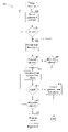
- FIG. 4 is a flowchart of method to be performed by a computer according to an embodiment of the invention.
- FIG. 5A is a diagram of one embodiment of an operating environment suitable for practicing the present invention.
- FIG. 5B is a diagram of one embodiment of a computer system suitable for use in the operating environment of FIG. 5A .
- FIGS. 1 , 2 A–B and 3 A–B A system level overview of the operation of an embodiment of the invention is described by reference to FIGS. 1 , 2 A–B and 3 A–B.
- a communication channel 120 is established between two computers, computer A 101 and computer B 103 .
- Computer B 103 may be a client connected to computer A 101 that is functioning as a server.
- Exemplary embodiments of the client and server computers and various communications channels are described in more detail below in conjunction with FIGS. 5A–B .
- the data flowing through the communication channel 120 is encoded into “protocol data units” (PDUs) according to a multi-layered data communication protocol.
- PDUs protocol data units
- An Ethernet network and the standard TCP/IP protocol stack are used as examples herein, but the invention is not so limited.
- protocol data units exchanged at the lowest protocol layer are referred to as “frames,” while those at the higher protocol layers are referred to as “packets.”
- packets those at the higher protocol layers
- PDUs the data exchanged at all layers
- Protocol data units in the communications channel 120 are captured in a frame capture buffer 105 using a standard protocol analysis tool and retrieved by a segmentation and re-assembly (SAR) decode engine 107 .
- SAR segmentation and re-assembly
- Multiple protocol interpreters, collectively shown at 111 are used by the SAR decode engine 107 to determine the appropriate sequencing or reassembly of the data into the data flow recognized by a particular protocol layer.
- the SAR decode engine 107 creates various flow objects to represent the data flows at each level and stores the flow objects in a flow object database 109 as described next.
- the SAR decode engine 107 is also responsible for unpacking the PDUs in creating the flow objects and for correctly re-assembling the data in the PDUs into the messages exchanged by the computers.
- the SAR decode engine 107 creates protocol flow objects to represent the protocol layers in the communication channel 120 and circuit flow objects to represent the data flow at a layer as decoded by the protocol interpreters 111 .
- One embodiment of a protocol flow object data structure is shown in FIG. 2A .
- the protocol flow object 200 contains a key 201 used to identify the particular protocol flow object within the flow object database 109 .
- the protocol flow object 201 also contains two circuit elements that link the circuit flow objects to the protocol flow object 201 .
- a primary circuit element 203 is linked to a series of circuit flow objects that represent the data being transmitted in one direction between the computers 101 and 103 and define a one-way circuit 121 in the communications channel 120 .
- An alternate circuit element 205 is linked to a series of circuit flow objects that define the opposite circuit 123 within the channel 120 .
- the primary circuit is determined by the transmission direction of the first PDU that is received in the frame capture buffer 105 but it will be appreciated that the primary and alternate circuits may be pre-determined based on various criteria, such as the whether the source computer functions as the client or server in a client-server network. It will further be appreciated that the key and the logical links can be address pointers, hash table values, or similar data structures conventionally used to locate and relate records within a data base or other data organization.
- the protocol flow objects created for the channel 120 are logically linked together by the SAR decode engine 270 in a hierarchical flow tree data structure.
- a corresponding flow tree 220 shown in FIG. 2B has at its base a root flow object 221 , which is linked to a data link layer protocol flow object, shown as DLC protocol object 223 .
- the network layer protocol is the Internet Protocol (IP) and is represented in the tree 220 by the IP protocol flow object 225 .
- IP Internet Protocol
- there are two connections between the computers at the transport protocol layer one for retrieving HTML formatted web pages using the HTTP application protocol and one for retrieving data from a Microsoft SQL database using a tabular data stream (TDS) protocol.
- TDS tabular data stream
- TCP protocol flow object 227 represents the connection between the two computers used to transport the requests for web pages and the corresponding web pages
- TCP protocol flow object 229 represents the connection that transports the SQL commands and resulting data.
- HTTP protocol flow object 231 and a Microsoft (MS) SQL protocol flow object 233 , linked to their respective TCP protocol objects.
- the key 201 for each protocol flow object may be either a source identifier, when it alone is sufficient to specify the appropriate protocol object, or a combination of both source and destination identifiers.
- the tree 220 shown in FIG. 2B is a simplified version of the types of hierarchical flow trees that can be created for the connections between two computers.
- each of the protocol flow objects in the tree 220 is further linked to the circuit flow objects that represent the primary and alternate circuits of the connection at that level.
- the circuit flow objects linked to a protocol flow object for a particular protocol layer represent the payloads of the PDUs for that layer.
- the circuit flow objects for a request will be linked to the primary circuit of a protocol object and the circuit flow objects for a reply will be linked to the alternate circuit.
- the configuration of the circuit flow objects depends upon the characteristics of the associated protocol layer.
- the circuit flow objects are not illustrated in FIGS. 2 B and 3 A–B to avoid obscuring the description of the present invention and the further details of the circuit flow objects are not necessary to understand the present invention.
- a detailed description of the SAR decode engine 107 and the various flow objects may be found in the related U.S. patent application Ser. No. 09/678,145.
- the SAR decode engine 107 identifies the primary and alternate circuits for a protocol flow object by the addresses in the PDUs, with the source-destination address pair for one circuit being the inverse of the source-destination address pair for the other circuit.
- the two corresponding circuits at the data link layer may have only one address in common, or no address at all, i.e. the data flows are multiplexed.
- An example of the flow tree data structure that represents multiplexed data flows is shown in FIG. 3A .
- the first PDUs captured in the buffer 105 for the channel 120 corresponds to an MS SQL database request from client computer B 103 to server computer A 101 .
- the SAR decode engine 107 creates a root flow object 301 for the connection, extracts the DLC address pair from the captured PDUs and creates a protocol flow object DLC A 303 for that address pair.
- the protocol interpreters 111 instruct the SAR decode engine 107 to create corresponding circuit flow objects, which are linked to the primary circuit of protocol flow object DLC A 303 .
- the SAR engine creates the higher layer protocol flow objects IP A 305 , TCP A 309 , and MS SQL A 313 , it also links the corresponding circuit flow objects to their primary circuits.
- the SAR decode engine 107 extracts the DLC address pair from the MS SQL database reply PDUs, the reply DLC address pair will not be the inverse of the request DLC pair because the data flows are multiplexed. Therefore, instead of linking the DLC circuit objects for the reply to the alternate circuit of protocol flow object DLC A 303 , the SAR decode creates a protocol flow object DLC B 315 and links the reply circuit flow objects to the primary circuit of protocol flow object DLC B 315 . The remaining protocol layers in the reply are unpacked into protocol flow objects IP B 317 , TCP B 319 , and MS SQL B 321 , with the corresponding circuit objects linked to their primary circuits. Since two separate flow trees are created for the request and reply, the reassembly of messages for a protocol that requires both the request and the reply data will fail.
- the present invention logically links the separate flow trees for the request and reply together at the application protocol layer when multiplexing has been enabled for the application protocol, as shown in FIG. 3B for MS SQL.
- the primary circuit flow objects for the reply protocol flow object 321 are logically linked to the alternate circuit of the request protocol flow object 313
- the primary circuit flow objects for the request protocol flow object 313 are logically linked to the alternate circuit of the reply protocol flow object 321 . It will be appreciated that the primary and alternate circuit flow objects at the lower protocol levels may be cross-linked as well if desired.
- the walk flow tree method 400 is invoked when a protocol flow object is created at the application layer and the application protocol requires matching requests and replies for proper analysis.
- the invocation may be set as a default for certain protocols, may be the default for all protocols, or may be requested for a particular protocol.
- the method 400 attempts to identify the branch of the flow tree that represents the request by matching the source-destination address pairs for the network and transport protocol flow objects with those of the reply branch.
- the method 400 records the source-destination address pair for each protocol flow object in the flow tree for the reply (block 401 ) until it reaches the root protocol flow object (block 403 ).
- the method 400 examines the set of link layer protocol flow objects attached to the root for a corresponding link layer protocol flow object that has one address in common with the addresses for reply link layer protocol flow object (block 405 ). Finding a corresponding link layer protocol flow object reduces the number of network and transport protocol flow objects that have to be examined to identify the request branch.
- the method 400 examines the network and transport protocol flow objects linked to it for address pairs that are the inverse of the address pairs for the reply network and transport protocol flow objects (block 411 ). Matching address pairs identify the request branch (block 413 ), and the application protocol flow object in the request branch is linked to the application protocol flow object in the reply branch as described above with reference to FIG. 3B (block 415 ). If none of the address pairs match (block 417 ), the method 400 assumes the reply is a “dangling” circuit, i.e., the corresponding request was not captured (block 419 ).
- the method 400 examines all the network and transport protocol flow objects attached to the set of link layer protocol flow objects for matching, but inverted, address pairs at block 411 until a match is found at block 413 , or the reply is assumed to be a dangling circuit at block 419 .
- the method 400 does not attempt to match the network and transport layer protocol flow objects if a corresponding reply data link layer flow object is not found at block 407 and proceeds directly to block 419 .
- the method 400 records only the source-destination address pairs for the network and transport protocol layers of the reply at block 401 as it walks down the reply branch of the flow tree and proceeds directly from block 403 to block 411 , where it examines all the network and transport protocol flow objects attached to the set of link layer protocol flow objects.
- the method 400 may be invoked when the application layer protocol flow object for a request is created but if the reply has not yet been captured, the method 400 will be unable to find the protocol flow objects for the reply. In this case, the method 400 will assume the request is a dangling circuit at block 419 , but will logically link the request and reply trees when the application layer protocol flow object for the reply is created and the method 400 is subsequently invoked. Furthermore, one of skill in the art will immediately understand that a request may be captured in the buffer 105 but not the subsequent reply, resulting in a dangling request circuit that cannot be matched.
- the method 400 may constitute one or more programs made up of machine-executable instructions. Describing the method with reference to the flowchart in FIG. 4 enables one skilled in the art to develop such programs, including such instructions to carry out the operations (acts) represented by logical blocks 401 until 419 on suitably configured machines (the processor of the machine executing the instructions from machine-readable media).
- the machine-executable instructions may be written in a computer programming language or may be embodied in firmware logic. If written in a programming language conforming to a recognized standard, such instructions can be executed on a variety of hardware platforms and for interface to a variety of operating systems.
- the present invention is not described with reference to any particular programming language.
- FIGS. 5A–B The following description of FIGS. 5A–B is intended to provide an overview of computer hardware and other operating components suitable for implementing the invention, but is not intended to limit the applicable environments.
- One of skill in the art will immediately appreciate that the invention can be practiced with other computer system configurations, including hand-held devices, multiprocessor systems, microprocessor-based or programmable consumer electronics, network PCs, minicomputers, mainframe computers, and the like.
- the invention can also be practiced in distributed computing environments where tasks are performed by remote processing devices that are linked through a communications network having a physical or wireless infrastructure, or a combination of both.
- FIG. 5A shows several computer systems that are coupled together through a network 3 , such as the Internet.
- the term “Internet” as used herein refers to a network of networks which uses certain protocols, such as the TCP/IP protocol, and possibly other protocols such as the hypertext transfer protocol (HTTP) for hypertext markup language (HTML) documents that make up the World Wide Web (web).
- HTTP hypertext transfer protocol
- HTML hypertext markup language
- the physical connections of the Internet and the protocols and communication procedures of the Internet are well known to those of skill in the art.
- Access to the Internet 3 is typically provided by Internet service providers (ISP), such as the ISPs 5 and 7 .
- ISP Internet service providers
- client computer systems 21 , 25 , 35 , and 37 obtain access to the Internet through the Internet service providers, such as ISPs 5 and 7 , through either physical or wireless interfaces.
- Access to the Internet allows users of the client computer systems to exchange information, receive and send e-mails, and view documents, such as documents which have been prepared in the HTML format.
- These documents are often provided by web servers, such as web server 9 which is considered to be “on” the Internet.
- web servers are provided by the ISPs, such as ISP 5 , although a computer system can be set up and connected to the Internet without that system being also an ISP as is well known in the art.
- the web server 9 is typically at least one computer system which operates as a server computer system and is configured to operate with the protocols of the World Wide Web and is coupled to the Internet.
- the web server 9 can be part of an ISP which provides access to the Internet for client systems.
- the web server 9 is shown coupled to the server computer system 11 which itself is coupled to web content 10 , which can be considered a form of a media database. It will be appreciated that while two computer systems 9 and 11 are shown in FIG. 4A , the web server system 9 and the server computer system 11 can be one computer system having different software components providing the web server functionality and the server functionality provided by the server computer system 11 which will be described further below.
- Client computer systems 21 , 25 , 35 , and 37 can each, with the appropriate web browsing software, view HTML pages provided by the web server 9 .
- the ISP 5 provides Internet connectivity to the client computer system 21 through the modem interface 23 which can be considered part of the client computer system 21 .
- the client computer system can be a personal computer system, a network computer, a Web TV system, a handheld wireless device, or other such computer system.
- the ISP 7 provides Internet connectivity for client systems 25 , 35 , and 37 , although as shown in FIG. 4A , the connections are not the same for these three computer systems.
- Client computer system 25 is coupled through a modem interface 27 while client computer systems 35 and 37 are part of a LAN. While FIG.
- FIG. 4A shows the interfaces 23 and 27 as generically as a “modem,” it will be appreciated that each of these interfaces can be an analog modem, ISDN modem, cable modem, satellite transmission interface (e.g. “Direct PC”), radio frequency (RF), cellular, or other interfaces for coupling a computer system to other computer systems.
- Client computer systems 35 and 37 are coupled to a LAN 33 through network interfaces 39 and 41 , which can be Ethernet network or other network interfaces.
- the LAN 33 is also coupled to a gateway computer system 31 which can provide firewall and other Internet related services for the local area network.
- This gateway computer system 31 is coupled to the ISP 7 to provide Internet connectivity to the client computer systems 35 and 37 .
- the gateway computer system 31 can be a conventional server computer system.
- the web server system 9 can be a conventional server computer system.
- a server computer system 43 can be directly coupled to the LAN 33 through a network interface 45 to provide files 47 and other services to the clients 35 , 37 , without the need to connect to the Internet through the gateway system 31 .
- FIG. 5B shows one example of a conventional computer system that can be used as a client computer system or a server computer system or as a web server system. It will also be appreciated that such a computer system can be used to perform many of the functions of an Internet service provider, such as ISP 5 .
- the computer system 51 interfaces to external systems through the modem or network interface 53 . It will be appreciated that the modem or network interface 53 can be considered to be part of the computer system 51 .
- This interface 53 can be an analog modem, ISDN modem, cable modem, token ring interface, satellite transmission interface (e.g. “Direct PC”), radio frequency (RF), cellular, or other interfaces for coupling a computer system to other computer systems.
- RF radio frequency
- the computer system 51 includes a processing unit 55 , which can be a conventional microprocessor such as an Intel Pentium microprocessor or Motorola Power PC microprocessor.
- Memory 59 is coupled to the processor 55 by a bus 57 .
- Memory 59 can be dynamic random access memory (DRAM) and can also include static RAM (SRAM).
- the bus 57 couples the processor 55 to the memory 59 and also to non-volatile storage 65 and to display controller 61 and to the input/output (I/O) controller 67 .
- the display controller 61 controls in the conventional manner a display on a display device 63 which can be a cathode ray tube (CRT) or liquid crystal display.
- CTR cathode ray tube
- the input/output devices 69 can include a keyboard, disk drives, printers, a scanner, and other input and output devices, including a mouse or other pointing device.
- the display controller 61 and the I/O controller 67 can be implemented with conventional well known technology.
- a digital image input device 71 can be a digital camera which is coupled to an I/O controller 67 in order to allow images from the digital camera to be input into the computer system 51 .
- the non-volatile storage 65 is often a magnetic hard disk, an optical disk, or another form of storage for large amounts of data. Some of this data is often written, by a direct memory access process, into memory 59 during execution of software in the computer system 51 .
- the term “computer-readable medium” includes any type of storage device that is accessible by the processor 55 and also encompasses a carrier wave that encodes a data signal.
- the computer system 51 is one example of many possible computer systems which have different architectures.
- personal computers based on an Intel microprocessor often have multiple buses, one of which can be an input/output (I/O) bus for the peripherals and one that directly connects the processor 55 and the memory 59 (often referred to as a memory bus).
- the buses are connected together through bridge components that perform any necessary translation due to differing bus protocols.
- Network computers are another type of computer system that can be used with the present invention.
- Network computers do not usually include a hard disk or other mass storage, and the executable programs are loaded from a network connection into the memory 59 for execution by the processor 55 .
- a Web TV system which is known in the art, is also considered to be a computer system according to the present invention, but it may lack some of the features shown in FIG. 5B , such as certain input or output devices.
- a typical computer system will usually include at least a processor, memory, and a bus coupling the memory to the processor.
- the computer system 51 is controlled by operating system software which includes a file management system, such as a disk operating system, which is part of the operating system software.
- a file management system such as a disk operating system
- One example of an operating system software with its associated file management system software is the family of operating systems known as Windows® from Microsoft Corporation of Redmond, Wash., and their associated file management systems.
- the file management system is typically stored in the non-volatile storage 65 and causes the processor 55 to execute the various acts required by the operating system to input and output data and to store data in memory, including storing files on the non-volatile storage 65 .
Abstract
Description
Claims (30)
Priority Applications (1)
| Application Number | Priority Date | Filing Date | Title |
|---|---|---|---|
| US10/154,933 US7103675B1 (en) | 2002-05-23 | 2002-05-23 | Multiplexed request and reply packets |
Applications Claiming Priority (1)
| Application Number | Priority Date | Filing Date | Title |
|---|---|---|---|
| US10/154,933 US7103675B1 (en) | 2002-05-23 | 2002-05-23 | Multiplexed request and reply packets |
Publications (1)
| Publication Number | Publication Date |
|---|---|
| US7103675B1 true US7103675B1 (en) | 2006-09-05 |
Family
ID=36939619
Family Applications (1)
| Application Number | Title | Priority Date | Filing Date |
|---|---|---|---|
| US10/154,933 Active 2025-04-19 US7103675B1 (en) | 2002-05-23 | 2002-05-23 | Multiplexed request and reply packets |
Country Status (1)
| Country | Link |
|---|---|
| US (1) | US7103675B1 (en) |
Cited By (4)
| Publication number | Priority date | Publication date | Assignee | Title |
|---|---|---|---|---|
| US20070055789A1 (en) * | 2005-09-08 | 2007-03-08 | Benoit Claise | Method and apparatus for managing routing of data elements |
| US20080109829A1 (en) * | 2006-11-03 | 2008-05-08 | Rockwell Automation Technologies, Inc. | Control and communications architecture |
| WO2012135221A1 (en) * | 2011-03-28 | 2012-10-04 | Citrix Systems, Inc. | Systems and methods for tracking application layer flow via a multi-connection intermediary device |
| EP2605480A1 (en) * | 2011-12-15 | 2013-06-19 | Mitsubishi Electric R&D Centre Europe B.V. | Apparatus and method for HTTP analysis |
Citations (9)
| Publication number | Priority date | Publication date | Assignee | Title |
|---|---|---|---|---|
| US5692168A (en) * | 1994-10-18 | 1997-11-25 | Cyrix Corporation | Prefetch buffer using flow control bit to identify changes of flow within the code stream |
| US5896537A (en) * | 1996-05-13 | 1999-04-20 | Siemens Corporate Research, Inc. | Partition based alias analyzer for pointers |
| US5913055A (en) * | 1995-09-20 | 1999-06-15 | Sharp Kabushiki Kaisha | Data driven information processor for executing and debugging a data flow graph without revising the data flow graph |
| US5933644A (en) * | 1997-06-18 | 1999-08-03 | Sun Microsystems, Inc. | Method and apparatus for conflict-based block reordering |
| US5933640A (en) * | 1997-02-26 | 1999-08-03 | Digital Equipment Corporation | Method for analyzing and presenting test execution flows of programs |
| US6014709A (en) | 1997-11-05 | 2000-01-11 | Unisys Corporation | Message flow protocol for avoiding deadlocks |
| US6119170A (en) | 1997-12-29 | 2000-09-12 | Bull Hn Information Systems Inc. | Method and apparatus for TCP/IP multihoming on a host system configured with multiple independent transport provider systems |
| US6122670A (en) | 1997-10-30 | 2000-09-19 | Tsi Telsys, Inc. | Apparatus and method for constructing data for transmission within a reliable communication protocol by performing portions of the protocol suite concurrently |
| US6697871B1 (en) | 1999-09-21 | 2004-02-24 | Network Associates Technology, Inc. | System and method for efficient encoding and decoding of protocol messages |
-
2002
- 2002-05-23 US US10/154,933 patent/US7103675B1/en active Active
Patent Citations (9)
| Publication number | Priority date | Publication date | Assignee | Title |
|---|---|---|---|---|
| US5692168A (en) * | 1994-10-18 | 1997-11-25 | Cyrix Corporation | Prefetch buffer using flow control bit to identify changes of flow within the code stream |
| US5913055A (en) * | 1995-09-20 | 1999-06-15 | Sharp Kabushiki Kaisha | Data driven information processor for executing and debugging a data flow graph without revising the data flow graph |
| US5896537A (en) * | 1996-05-13 | 1999-04-20 | Siemens Corporate Research, Inc. | Partition based alias analyzer for pointers |
| US5933640A (en) * | 1997-02-26 | 1999-08-03 | Digital Equipment Corporation | Method for analyzing and presenting test execution flows of programs |
| US5933644A (en) * | 1997-06-18 | 1999-08-03 | Sun Microsystems, Inc. | Method and apparatus for conflict-based block reordering |
| US6122670A (en) | 1997-10-30 | 2000-09-19 | Tsi Telsys, Inc. | Apparatus and method for constructing data for transmission within a reliable communication protocol by performing portions of the protocol suite concurrently |
| US6014709A (en) | 1997-11-05 | 2000-01-11 | Unisys Corporation | Message flow protocol for avoiding deadlocks |
| US6119170A (en) | 1997-12-29 | 2000-09-12 | Bull Hn Information Systems Inc. | Method and apparatus for TCP/IP multihoming on a host system configured with multiple independent transport provider systems |
| US6697871B1 (en) | 1999-09-21 | 2004-02-24 | Network Associates Technology, Inc. | System and method for efficient encoding and decoding of protocol messages |
Non-Patent Citations (1)
| Title |
|---|
| Stevens, W. Richard, TCP/IP Illustrated, vol. 1, 1994, Addison Wesley, pp. 1248-1251. |
Cited By (6)
| Publication number | Priority date | Publication date | Assignee | Title |
|---|---|---|---|---|
| US20070055789A1 (en) * | 2005-09-08 | 2007-03-08 | Benoit Claise | Method and apparatus for managing routing of data elements |
| US20080109829A1 (en) * | 2006-11-03 | 2008-05-08 | Rockwell Automation Technologies, Inc. | Control and communications architecture |
| US8458350B2 (en) | 2006-11-03 | 2013-06-04 | Rockwell Automation Technologies, Inc. | Control and communications architecture |
| WO2012135221A1 (en) * | 2011-03-28 | 2012-10-04 | Citrix Systems, Inc. | Systems and methods for tracking application layer flow via a multi-connection intermediary device |
| US9571354B2 (en) | 2011-03-28 | 2017-02-14 | Citrix Systems, Inc. | Systems and methods for tracking application layer flow via a multi-connection intermediary device |
| EP2605480A1 (en) * | 2011-12-15 | 2013-06-19 | Mitsubishi Electric R&D Centre Europe B.V. | Apparatus and method for HTTP analysis |
Similar Documents
| Publication | Publication Date | Title |
|---|---|---|
| US7181748B2 (en) | Multi-layer protocol reassembly that operates independently of underlying protocols, and resulting vector list corresponding thereto | |
| US6385615B1 (en) | Communicating network information using universal resource locators | |
| US6275937B1 (en) | Collaborative server processing of content and meta-information with application to virus checking in a server network | |
| US7421515B2 (en) | Method and system for communications network | |
| US8001254B1 (en) | Translating switch and method | |
| JP4363847B2 (en) | Digital TV application protocol for interactive TV | |
| US7134075B2 (en) | Conversion of documents between XML and processor efficient MXML in content based routing networks | |
| US6792461B1 (en) | System and method to manage data to a plurality of proxy servers through a router by application level protocol and an authorized list | |
| US5966451A (en) | Distributed network computing system, and data exchange apparatus and method and storage medium used in this system | |
| US7685287B2 (en) | Method and system for layering an infinite request/reply data stream on finite, unidirectional, time-limited transports | |
| US8176164B1 (en) | Method and system for managing network traffic | |
| US6604241B1 (en) | Communicating video information in a network using universal resource locators | |
| US7636353B2 (en) | Method and system for transmitting data over a network | |
| US20020023145A1 (en) | System and method to accelerate client/server interactions using predictive requests | |
| US20040047349A1 (en) | Packet transfer equipment, packet transfer method resolution server, DNS server, network system and program | |
| US20130254258A1 (en) | Offloading application components to edge servers | |
| US20070033293A1 (en) | Techniques for delivering personalized content with a real-time routing network | |
| US20090046726A1 (en) | Virtual network with adaptive dispatcher | |
| US7082471B2 (en) | Method and system of dispatching socks traffic using type of service (TOS) field of IP datagrams | |
| WO1997049252A2 (en) | Network based programmable media manipulator | |
| US20030028681A1 (en) | Apparatus and method for port sharing among a plurality of server processes | |
| US7779087B2 (en) | Processing numeric addresses in a network router | |
| US7219125B1 (en) | Method and apparatus for masking version differences in applications using a data object exchange protocol | |
| US6799215B1 (en) | Method and apparatus for providing logical unit definitions for telenet servers | |
| US7103675B1 (en) | Multiplexed request and reply packets |
Legal Events
| Date | Code | Title | Description |
|---|---|---|---|
| AS | Assignment |
Owner name: NETWORKS ASSOCIATES TECHNOLOGY, INC., CALIFORNIA Free format text: ASSIGNMENT OF ASSIGNORS INTEREST;ASSIGNOR:FREEDMAN, JEROME NORMAN;REEL/FRAME:012944/0299 Effective date: 20020522 |
|
| AS | Assignment |
Owner name: NETWORK GENERAL TECHNOLOGY, CAYMAN ISLANDS Free format text: ASSIGNMENT OF ASSIGNORS INTEREST;ASSIGNOR:NETWORKS ASSOCIATES TECHNOLOGY, INC.;REEL/FRAME:015271/0031 Effective date: 20040713 |
|
| AS | Assignment |
Owner name: NETWORK GENERAL TECHNOLOGY, CAYMAN ISLANDS Free format text: ASSIGNMENT OF ASSIGNORS INTEREST;ASSIGNOR:NETWORKS ASSOCIATES TECHNOLOGY, INC.;REEL/FRAME:015279/0053 Effective date: 20040713 |
|
| STCF | Information on status: patent grant |
Free format text: PATENTED CASE |
|
| FPAY | Fee payment |
Year of fee payment: 4 |
|
| FPAY | Fee payment |
Year of fee payment: 8 |
|
| MAFP | Maintenance fee payment |
Free format text: PAYMENT OF MAINTENANCE FEE, 12TH YEAR, LARGE ENTITY (ORIGINAL EVENT CODE: M1553) Year of fee payment: 12 |