US7725501B1 - System and method for rapid database application deployment and use - Google Patents
System and method for rapid database application deployment and use Download PDFInfo
- Publication number
- US7725501B1 US7725501B1 US11/271,923 US27192305A US7725501B1 US 7725501 B1 US7725501 B1 US 7725501B1 US 27192305 A US27192305 A US 27192305A US 7725501 B1 US7725501 B1 US 7725501B1
- Authority
- US
- United States
- Prior art keywords
- database
- user
- data
- database application
- property
- Prior art date
- Legal status (The legal status is an assumption and is not a legal conclusion. Google has not performed a legal analysis and makes no representation as to the accuracy of the status listed.)
- Active, expires
Links
Images


Classifications
-
- G—PHYSICS
- G06—COMPUTING; CALCULATING OR COUNTING
- G06F—ELECTRIC DIGITAL DATA PROCESSING
- G06F16/00—Information retrieval; Database structures therefor; File system structures therefor
- G06F16/20—Information retrieval; Database structures therefor; File system structures therefor of structured data, e.g. relational data
- G06F16/28—Databases characterised by their database models, e.g. relational or object models
- G06F16/289—Object oriented databases
-
- G—PHYSICS
- G06—COMPUTING; CALCULATING OR COUNTING
- G06F—ELECTRIC DIGITAL DATA PROCESSING
- G06F16/00—Information retrieval; Database structures therefor; File system structures therefor
- G06F16/20—Information retrieval; Database structures therefor; File system structures therefor of structured data, e.g. relational data
- G06F16/28—Databases characterised by their database models, e.g. relational or object models
- G06F16/284—Relational databases
Definitions
- a relational database is a database in which the database is perceived by its users as a collection of tables and operators at the user's disposal (e.g., for data retrieval) are operators that generate new tables from old. See, e.g., “An Introduction to Database Systems,” C. J. Date, Vol. I, Fourth Edition, pg. 20 (1986).
- the user interface design and development (step 3) usually includes high level design, detailed design, coding, testing, system integration, and deployment phases. As such, the user interface design and development is usually the most time consuming activity. As a simple example, a complete database and user interface effort might require two (2) months to derive the database structure (step 1), one (1) month to implement the structure (step 2), and twelve (12) months to create the user interface (step 3). Moreover, after the database and user interface development is completed, any required data structure changes will necessitate a repeat of all three steps, although typically at a smaller scale than the original development effort. Such changes and iterations are normal during the lifetime of any database application.
- the operating system, database, and user environment additionally detect, manage, process, and protect individual database elements based on a security classification labeling model.
- Information retrieval in this data environment includes capabilities to determine the level of classification a user may receive, and restrict data retrieved from the relational database for display to a level not exceeding the user's authorized level.
- a conventional approach to database and user interface development following the described model would entail dedicated time between technical staff (e.g., database and software engineers) and the information domain/subject matter experts in developing an information hierarchy, model, and general rule set.
- a formal relational data structure would then be built based on this knowledge containing the required data tables, linking tables, constraints, rules, and triggers required to maintain data integrity throughout the planned database lifecycle.
- User interface screens would be typically developed by separate software specialists to provide the required user functionality, display characteristics, and input validation, with integration of each screen into a composite application directly linked to the underlying database structure. Deployment of the initial database application would entail exhaustive testing of data entry, retrieval, error trapping, desired application flow, and an initial population with test or demonstration data.
- the database application is required to operate in a secure environment, e.g., a DoD mandated secure environment, specific tests demonstrating handling, protection, storage, and retrieval of classified data will additionally be necessary prior to end user delivery.
- a secure environment e.g., a DoD mandated secure environment
- specific tests demonstrating handling, protection, storage, and retrieval of classified data will additionally be necessary prior to end user delivery.
- the database may be declared formally available for end-user training and the initial population begins.
- a typical deployment of a database and application will result in user-identified errors and requests for changes in the interface, functionality, or underlying data structure.
- the development team must identify the source, if an error, and correct it through recoding and recompiling, or for change requests, modify the database or user interface elements through redesign, recoding, and recompiling, prior to deploying a next version of the database application.
- this may entail a complete halt in use of the database during the maintenance period, resulting in a loss of productivity where use of the database was required.
- the conventional approach for developing and deploying an integrated user interface and supporting relational database infrastructure requires substantial planning, design, development, and testing prior to delivery to the end user.
- the underlying information domain or required data content may substantially change during the course of the development process. This results in an immediate need to begin redesign, integration, and test as soon as the database is officially declared an operational capability.
- the cost of the time required to follow a conventional database development process cannot meet the need for relational database and user interface support required for the critical analyses or operational tasks increasingly common in government and commercial activities today.
- a system that includes a host server, the host server containing a database and a database application framework.
- the database stores a virtual relational database structure and a virtual relational database implementation.
- the database may store the virtual relational database structure and virtual relational database implementation in an existing relational database structure.
- the virtual relational database structure includes one or more object types and one or more object properties.
- Object types are definitions of types of objects for which data may be stored in the database
- object properties are definitions of types of data that may be stored for objects and are associated with the one or more object types.
- the virtual relational database implementation includes one or more actual objects that are based on the one or more object types and one or more populated properties that are based on the object properties and which include data for the one or more actual objects.
- the database application framework enables a user to define virtual relational database structures and create relational database implementations.
- the database application framework communicates with the database and includes user interface software that creates and processes user interface displays that enable a user to view, edit and search the database and which adapt to changes to the virtual relational database structure to immediately reflect such changes on the user interface displays.
- the computer readable medium includes a database application framework that enables a user to define virtual relational database structures and create virtual relational database implementations.
- the database application framework includes user interface software that creates and processes user interface displays that enable a user to view, edit and search a database and which adapt to changes to the virtual relational database structure to immediately reflect such changes on the user interface displays.
- the method includes creating a virtual relational database structure and implementing a virtual relational database based on the relational database structure.
- the creating of the virtual relational database structure includes receiving a user definition of the virtual relational database structure on a web page, creating one or more user-defined object types based on the received user definition and creating one or more user-defined object properties based on the received user definition.
- the object types are definitions of types of objects for which data may be stored in the virtual relational database.
- the object properties are definitions of types of data that may be stored for objects and are associated with the one or more object types.
- the implementing of a virtual relational database includes receiving user input on a web page, creating one or more actual objects based on the received user input, and creating one or more populated properties based on the received user input.
- the one or more actual objects are based on the object types in the relational database structure and the one or more populated properties are based on the object properties and include data for the one or more actual objects.
- FIG. 1 is a block diagram of software components of an embodiment of a system and method for rapid database application deployment and use.
- FIG. 3 is a flowchart of an embodiment of a method for processing and displaying an objects selection page in an embodiment of a method for rapid database application deployment and use.
- FIGS. 5A-5B are flowcharts of an embodiment of a method for processing and displaying property definition search pages in an embodiment of a method for rapid database application deployment and use.
- FIG. 6 is a flowchart of an embodiment of a method for processing and displaying an object display page in an embodiment of a method for rapid database application deployment and use.
- FIGS. 7A-7B are flowcharts of an embodiment of a method for processing and displaying an object property edit page in an embodiment of a method for rapid database application deployment and use.
- FIGS. 8A-8B are flowcharts of an embodiment of a method for processing and displaying object property search pages in an embodiment of a method for rapid database application deployment and use.
- FIG. 9 is a flowchart of an embodiment of a method for processing exemplary triggers in an embodiment of a method for rapid database application deployment and use.
- FIG. 10 is a flowchart of an embodiment of a method for processing exemplary triggers in an embodiment of a method for rapid database application deployment and use.
- FIG. 11 is a block diagram illustrating exemplary hardware components for implementing an embodiment of a system and method for rapid database application deployment and use.
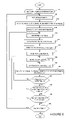
- FIG. 12 is a flowchart illustrating an embodiment of a method for rapid database application deployment and use.
- Embodiments of the system and method for rapid database application deployment and use may be implemented by a database application framework.
- Database application framework mitigates the shortfall of database development through a unique and novel solution.
- the database and software development required for both the underlying database structure and user interface have been integrated in database application framework, a user-driven application, optimized to support a dynamic information environment as described herein.
- Database application framework provides end users with capabilities to define and deploy a virtual relational database structure and user interface in concert with their increasing awareness of their specific information domain and database needs.
- Embodiments of database application framework implement an underlying, existing relational database structure which allows the user to create virtual relational database structures and virtual relational database implementations/applications.
- a virtual relational database structure is a collection of information presented to a user which appears as it would in a conventional relational database, but which is stored and manipulated in a non-conventional manner.
- the virtual structure allows for conventional user actions such as viewing, editing (insert/update/delete), and searching.
- the database application framework presents virtual relational database structures, and virtual relational database implementations based thereupon, created using the database application framework, so that they appear as conventional relational databases.
- the interface created by the database application framework allows users to view, edit, and search virtual relational database structures and virtual relational database implementations created therewith.
- the database application framework stores and manipulates virtual relational database structures in a non-conventional manner.
- Embodiments of the database application framework store the virtual relational database structures in an existing, static relational database structure.
- the existing, static relational database structure includes pre-defined, existing tables for storing components that make up the virtual relational database structures (e.g., object types, objects, categories, properties).
- Embodiments include a set, pre-defined number of tables for each component; generally, there is one table for each component (e.g., an embodiment includes one “object type” table, one “objects” table, one “categories” table, etc.), although some components may have two or more tables (e.g., an embodiment may include two “property” tables).
- An exemplary listing of the pre-defined, existing tables in an embodiment of database application framework is shown in Appendix A attached hereto.
- a virtual relational database implementation is an implementation or application of a virtual relational database structure created using database application framework. Although discussed as separate from the virtual relational database structure, the virtual relational database implementation is stored with the virtual relational database structure.
- the virtual relational database comprises the virtual relational database structure (e.g., object types, properties, object categories, etc.) and the virtual relational database implementation (e.g., objects, populated properties, etc.) created therewith.
- database application framework As database application framework is used, there are no changes made to the existing, static relational database structure.
- the pre-defined tables will not be changed in any way as a result of or by user actions, other than database application framework adding rows of data corresponding to, e.g., new object types, objects, categories, properties, and other data input by the user.
- Users cannot add columns to the pre-existing tables, cannot add new tables to the existing, static relational database structure, and cannot change relationships between the pre-defined, existing tables.
- the new object type created by the user will be processed by database application framework and added to the pre-existing object types table as a new row of data.
- Each instance of database application framework will include the same existing, static relational database structure. Only structural changes made to this existing, static relational database structure would be as a software update to database application framework in which new pre-defined tables were added to correspond to new types of components for the virtual relational database structure, or similar changes. These changes would not be made by end-users of database application framework.
- Database application framework may include a database and web interface that (a) allows end users to define and change the structure of a virtual relational database to suit their needs and (b) provides editing (insert/update/delete), viewing, and searching user interface (i.e., database access) web pages that immediately adapt to any changes in the structure without the need to rewrite, recompile, or in any way change the web page software. This allows for the rapid standup of a database and user interface application/implementation without the need for database or software engineers. Database application framework allows a user to rapidly develop secure database applications, without database or software modifications or the need for database and software engineers
- database application framework provides the user a capability to “populate through participation” the information structure based on a pre-designed, tested, and deployed generalized data model, structure and user-interface.
- Database application framework provides capabilities for definition, storage, retrieval, and modification of required data and user display elements.
- Database application framework enables users to begin building their database application even if they cannot completely define their data requirements for the database itself. As those needs evolve, database application framework provides users the ability to dynamically update the data structure, relationships, and desired display formats. Database application framework user interface adapts to changes made in structure, display formats, or entity relationships the moment the change is made. User interface screens providing browsing, editing and search functions automatically reflect these changes once saved in the database. Database application framework effectively eliminates the need for lengthy, costly software design, development, and test stages from database deployment, use, and maintenance. Changes to virtual database structure are immediately reflected in the user interface without the need to repeat the steps (1), (2), and (3) described above (see Background).
- Database application framework eliminates the need for database engineers in the database definition and creation steps (steps 1 and 2) and simplifies the database structure development steps by providing a simple but powerful general purpose database model that end users can understand and manipulate as necessary by themselves to fit their needs.
- Database application framework completely eliminates the user interface design and development step (step 3) by creating intelligent editing, viewing, and searching web pages that automatically react and conform to the database structure that the user has implemented.
- Database Definition Subject matter experts and/or end users work together to derive the underlying structure of the database.
- Database Creation End users implement the derived database structure from step 1 via database application framework structure definition web pages to create a virtual relational database implementation.
- step 2 database application framework web pages that allow end users to edit, view, and search (i.e., use) the database are immediately available because these pages adapt themselves to the new structure. Indeed, an entire new database implementation need not be completed before a user can edit, view, and search the database.
- a user may define a portion of the database structure (step 1), input some data (i.e., implement the derived database structure to create some portion of the database (step 2)), and immediately begin editing, viewing, and searching the database.
- the user may define further portions of the database structure and input additional data to further populate the database, with such changes being immediately reflected in the user interface web pages generated by database application framework and used by the user to edit, view and search the database.
- a primary advantage of the system and method for rapid database application deployment and use is the significant savings of time, money, and resources.
- the savings occurs because the end users can implement and change their structure themselves as needed without having to wait for and pay for database and software engineers to implement a new structure and the corresponding web pages.
- database application framework is ideally suited for situations, for example, in which: (a) users do not have a clear and thorough understanding of their data structure requirements, and therefore need a structure and user interface that is flexible and that can adapt to new or changing needs; (b) users do not have the time, money, and/or resources (database and software engineers) required for a typical custom database and interface development effort; (c) users wish to prototype a database structure in a proof-of-concept mode prior to committing to a long database and interface development effort; and, (d) users wish to field a database and user interface immediately while developing a customized database and interface in parallel.
- System 5 includes database application framework 10 .
- database application framework 10 may be implemented as a user-driven software application comprising stored code, and may include user interface software 12 and triggers 14 .
- the user interfaces are web pages, although other user interfaces may be used.
- the web pages may include various web pages such as are described below and shown in the '868 provisional, which is incorporated by reference above.
- User interface software 12 may include creator and receiver modules or programs for creating and receiving data from database interface web pages. These programs may be, for example, server side include (SSI) or common gateway interface (CGI) programs.
- SSI server side
- CGI common gateway interface
- user interface software 12 is implemented as creator and receiver CGI programs, which are discussed below.
- Each web page provided by database application framework 10 for database interface may have its own dedicated creator and/or receiver CGI programs.
- system 5 shown includes web browser 16 , web server 18 , optional database label security application 20 and database 22 .
- the database 22 may include the relational database structure implemented by database application framework to create virtual relational database structures and virtual relational database implementations.
- the database 22 may store virtual relational database structures and virtual relational database implementations (the data). The following is a description of the use of the embodiment of system 5 shown in FIG. 1 .
- database application framework 10 is installed and running on a computer (e.g., a server), a user of system 5 may interact with database application framework 10 through the web browser 16 to create a virtual relational database structure and a virtual relational database implementation. Users select specific functions from predefined links on database application framework web pages, and/or enter data and submit the request to database application framework 10 . Information from the user is transferred from web browser 16 (e.g., through a URL) which sends a request to system web server 18 , to produce a specific action. The action may entail web server 18 transmitting a specific request to database application framework 10 to activate user interface software 12 (e.g., a specific CGI program) to act on input from the user request.
- user interface software 12 e.g., a specific CGI program
- the user request is satisfied by executing designated user interface software 12 to handle the user request, then executing user interface software 12 to generate data (e.g., HTML data) for submission to web server 18 , for creation and display of the resulting web page to the user on web browser 16 .
- data e.g., HTML data
- database label security application 20 When user requests require data retrieval from database 22 , user interface software 12 creates the appropriate database request message or query (e.g., a Structured Query Language (SQL) statement). If database label security application 20 is present (i.e., database application framework is operating in an active row-labeling security environment), database application framework 10 submits the database request message to database label security application 20 (e.g., ORACLE®'s label security application). If required, database label security application 20 interprets the information request and queries database 22 for the required data. In a non row-labeling security environment, the database request from database application framework 10 is passed directly to database 22 .
- SQL Structured Query Language
- the queried data returned from database 22 is further interpreted by database label security application 20 to determine what data elements meet the original user request, based on user security access.
- This resulting dataset is returned to appropriate user interface software 12 .
- User interface software 12 then performs required processing of the data to generate the data (e.g., HTML data) for submission to web server 18 and display as a web page on web browser 16 .
- Web server 18 receives the database application framework 10 generated data file and passes the resulting web page display file to web browser 16 for user display.
- Database application framework 10 Users may select specific database application framework 10 edit functions from predefined links on a database application framework 10 web page. Information from the user is transferred from web browser 16 , e.g., through a URL which sends a request to system web server 18 , to produce a specific action. User edit requests require specific data retrieval and insertion in database 22 , provided by user interface software 12 . Software in database application framework 10 executes in response to the user edit request and creates the appropriate database requests and submits the requests to database label security application 20 , if database application framework 10 is operating in an active row-labeling security environment. If required, database label security application 20 interprets the information request and queries database 22 for the required data.
- the database request from database application framework 10 is passed directly to database 22 .
- the queried data returned from database 22 is further interpreted by database label security application 20 to determine what data elements meet the original user request, based on user security access.
- This resulting dataset is returned to appropriate user interface software 12 .
- User interface software 12 then performs required processing of the data to generate the data to create the data (e.g., HTML data) for submission to web server 18 and display as a web page on web browser 16 .
- Web server 18 receives the database application framework 10 generated data file and passes the resulting web page display file to web browser 16 for user display.
- a user edit display web page provides options for modification, deletion, and/or addition of data in database 22 .
- This data includes both information describing the virtual database content and structure. Any changes to the structure or content of the database requires execution of single or multiple combinations of one or more database application framework 10 edit functions.
- User interface software 12 executes, interprets the requested action, and forms a structured language statement for database update, which is passed to database application framework triggers 14 .
- Triggers 14 are integrated as integral elements of the database to ensure data integrity is maintained.
- a specific set of database triggers 14 automatically verifies the database update request for data content, data validity, and format.
- a second set of triggers 14 identified as Cascading Row-label Triggers, specifically execute if database application framework 10 is implemented in a row-labeling security environment.
- triggers parse and validate the security labels of the update request, determine the required row-label security required for existing and new database rows based on implementation of the requested change, and submit the resulting data set to the database 22 for final database update.
- the results of the user requested database update are then displayed following steps described previously for display/browsing/viewing.
- Embodiments of system 5 are used as described above to both develop and use (e.g., edit, view, search) a relational database.
- database application framework 10 a user can define the virtual database structure of their relational database as they choose. Moreover, the user can begin using their database without completely defining the virtual database structure. In other words, the user can partially define the database structure and begin using the database.
- Database application framework 10 enables this by allowing users to: define the types of things—objects—they want the database to store (after defining, the user can then create objects of those types); define what types of information they want the database to store for those objects (after defining the types of information, the users can then enter data for those objects); and associate objects together and define the relationships between those objects. Consequently, embodiments of system 5 are centered around two core concepts: objects and properties.
- An object is an individual entity that stored data is to be related with. Examples of objects are employees, satellites, buildings, cars, students, computers, books, etc.
- additional entities can be added simply and quickly to database tables.
- types of entities i.e., types of objects
- the new information could not be easily added because there would be no structure and user interface designed to support the addition of vehicles.
- object types may be defined by any appropriately authorized end user.
- database application framework 10 In the same company database example using database application framework 10 , a user would create a new object type called “vehicles” and all appropriately authorized users would be able to create objects that are vehicles and add them to the database.
- Variable object types allow database application framework 10 to support completely different database information domains and to change very easily and quickly when required. Once an object type is created (or changed), database application framework 10 user interfaces (e.g., web pages) immediately adapt to support the object type (or its changes).
- Object types provide a first level grouping of objects, and object categories provide a second level. For example, if the “vehicles” object type existed, the object categories “cars,” “vans,” and “trucks” could be created to subdivide “vehicles.” This provides an aid to the user when trying to find related objects of interest.
- Each object must have a unique name (different from every other object name in the database), must be assigned an object type (from the list of user defined object types), and must be assigned an object category (from the list of user defined object categories).
- a property is a group of related pieces of data that is stored related to an object. For example, for an employee in the previous example, a requirement may exist to store the social security number, hire date, position, and manager. For a vehicle object, the requirement may be to store the manufacturer, model, year, VIN, license number, and color. From a user's point of view a property is essentially the same as a database table. A property has defined columns (manufacturer, model, year, etc.) and when data is entered into a property it is entered into rows.
- database application framework 10 the end user creates the properties, e.g., via database application framework 10 property definition web pages.
- the user provides the name of the property, some information about how the property is to be displayed, and information about each column in the property.
- the column information includes such data as column name, data type, size, input format, units, minimum/maximum allowed value, and metadata (data about the data) storage options for priority, source, comment, timestamp, and user name.
- This property information is very similar to what would be required to create an actual database table in a database design phase. This information about the property is completely stored in database 22 .
- FIG. 2 shown is a block diagram illustrating logical components of an implementation of a relational database created using database application framework 10 . As illustrated, the logical components are all stored in database 22 . Other virtual relational database implementations created using the same database application framework 10 may be stored in the same database 22 .
- the virtual relational database implementation or application 30 in the example shown is a Counter-Terrorism Database.
- Relational database 30 includes object types 32 and properties 36 that were defined by a user and created and stored in database 22 by database application framework 10 . Relational database 30 may also include object categories 34 that were defined by a user and created and stored in database 22 by database application framework 10 .
- a user may create one or more individual objects 38 of that object type 32 . Each object type 32 may include one or more properties 36 associated to the object type 32 . Whenever an individual object 38 is created, the object 38 may be associated with one or more of the properties 36 associated to its object type 32 .
- a user In order to enter data for an object, a user first selects (e.g., on a database application framework 10 web page) the object to enter data for and the property that defines the appropriate type of data the user wishes to enter. For example, if an employee object named “John Smith” was created and if a property called “Employee Hiring Info” (containing columns for social security number, hire date, position, and manager) was created, the user would select the “John Smith” object and the “Employee Hiring Info” property to associate the object and the property together.
- An object property editing page that provides for property data entry (in this case, the actual social security number, hire date, position, and manager for John Smith) examines the property definition (column names, data types, sizes, input formats, etc.) and displays the appropriate input fields for each property column in order to allow data entry and/or data modification by the user. Because the object property editing page is utilizing the stored property definition to determine what fields to display, the page can accommodate any property definition (any number of columns with any combination of the various allowed data types) and can immediately accommodate any changes the user makes to a property definition.
- the object property editing page did not require modifying or recompiling or change in any way to accommodate the new salary column.
- Other types of changes such as switching column positions or changing a column's name, size, input format, or minimum/maximum allowed values are also immediately accommodated by the object property editing web page.
- database application framework 10 allows multiple values to be stored in a cell. If, for example, a “degree” column was added to the “Employee Hiring Info” property above, a user could enter “BS—Computer Science” and “MS—Business Administration” in the “degree” cell for a specific employee. These two items would physically be stored as separate values in the underlying database application framework 10 structure (in database 22 ) not as two text strings concatenated together into one large string value. In database application framework 10 the two values then would appear together in a single cell when viewed by the user.
- An object display page (which displays all data about a single object) works in a similar manner as the object property editing page in that it examines the definition of each property associated with an object being displayed and displays the user entered data for each property accordingly. If the salary column mentioned above were to be added to a property, the next time this property was displayed that column would appear, albeit empty (until the user enters salary data into those property rows previously added). Whereas the object property edit page is formatted in a “database-ish” manner to accommodate data entry, the object display page is designed to present property data in a simple, user-friendly table or list format.
- the creation of a property does not cause the creation of an actual database table.
- user actions do not cause any database tables to be created when using database application framework 10 .
- object types are stored in a table
- object categories are stored in a different table
- objects are stored in yet another table.
- property definitions are stored in two tables, a first table that stores information about the property as a whole (e.g., the property name, how it is to be displayed, where it is to be displayed in relation to other properties, etc.) and a second table that stores information about each column in a property.
- the answer is that all property data (again, this is, for example, the actual social security number, hire date, position and manager for a specific employee object) is stored in a single table called the “object property cell values” table, which is maintained in database 22 .
- all property data for all objects is stored in a single table.
- relationships between the “things” you want to store data for must be determined during the database design.
- Table columns and/or entire tables are added to establish relationships.
- the relationship data in a database usually only defines existence of a relationship and does not define the nature of the relationship.
- a database can be defined to clearly indicate there is a relationship between employees and departments and between employees and vehicles, but it does not store the type or meaning of the relationships, such as “employees are in departments” or “employees use vehicles”. That type of information is usually built into the software application that displays the data from the database, so that it can display the appropriate information to the user.
- An application would be coded so that any relationships between, for example, employees and departments by definition would mean the employees are in the departments and the departments contain the employees.
- properties can be created to store information about a relationship between objects, a link object can be created and associated to those properties, and the appropriate property data can be stored.
- the link object then “sits” between the related objects to identify the relationship and the associated supplemental information about the relationship.
- database label security application 20 may be used if database application framework 10 is operating in an active row-labeling security environment.
- An example security environment is if the relational database developed using database application framework 10 has security requirements in which access to data is restricted based on each user's assigned security clearance (e.g., confidential, secret, top-secret, etc.).
- Oracle Corporation provides an optional feature for its databases called Oracle Label Security (OLS)TM.
- OLS is an exemplary database label security application 20 .
- OLS is an exemplary database label security application 20 .
- every row of data in the database includes an extra “label” column that indicates the security clearance level that a user must have in order to access the row.
- every user is assigned a clearance level.
- database label security application 20 compares the user's clearance with the clearances of the possible rows to return and only returns those rows that the user is allowed to access.
- Database label security application 20 is completely automatic in that the queries against database 22 are exactly the same as those without database label security application 20 . This insures that no query can be written to bypass database label security. The only difference is that with database label security application 20 , when data is inserted into database 22 the label column value must be specified.
- database application framework 10 works with or without database label security application 20 .
- triggers 14 written for database application framework 10 are utilized.
- a trigger 14 is a piece of custom software that a database executes automatically when a designated event occurs.
- the events the triggers trap are any insertions or updates of any tables.
- a trigger 14 executes to examine the data that is being inserted or updated. Specifically, any and all user-entered classification markings (entered either standalone or portion marking embedded at the beginning of a text paragraph) are extracted and an overall classification for the row being inserted or updated is calculated and set.
- triggers 14 instead of adding database label security-related code (e.g., OLS code) to user interface software 12 has two advantages.
- the normal interface (e.g., web page) code to insert and update data does not depend on whether database label security application 20 is employed or not. If database label security application 20 is implemented, triggers 14 take care of setting the label of a row upon insert or update. If not, triggers 14 simply skip all row label processing code. This simplifies user interface software 12 code (e.g., web page code) so that it does not need to act differently based on the presence or absence of database label security application 20 .
- using triggers 14 allows for labels to be correctly calculated and set regardless of how the data is being inserted or updated.
- Database application framework 10 is the primary application that will be inserting and updating data. But other applications could be written to access the same data, and a database administrator may have the ability to insert or update data via a variety of tools (e.g., Oracle tools) if necessary. Since triggers 14 are executed automatically by database 22 any time there is an insert or update, the triggers will handle database label security application 20 requirements regardless of the method used for data manipulation or user interface.
- tools e.g., Oracle tools
- triggers 14 there are a variety of ways a database developer could implement triggers 14 to determine, set, and utilize the row label columns.
- the simplest method is to have the trigger 14 analyze the data to be inserted into a row and then determine the value of an overall row label. The information in the row would be sufficiently protected so only authorized users could access data in the row.
- This method does not provide sufficient protection for data structures in a hierarchical situation. In a hierarchy, one table is dependent upon another. In a relational database it is normal for many hierarchical relationships of this kind to exist between tables.
- a user logged into the database with a Secret or higher security clearance level would be permitted to see that “John Smith” worked on the “Stealth Fighter” project as a “Programmer”.
- a user logged into the same database with an Unclassified security clearance level would (depending upon how the queries were written) be permitted to see that “John Smith” worked on a project as a “Programmer” but could't see the name of the project. This could present a security loophole because the Unclassified user has some information about a project they are not permitted to access.
- the “Programmer” record should automatically be labeled at a Secret level although the “Programmer” data is Unclassified. Given this capability, the same Unclassified user could access “John Smith” but not any results related to the assignment as a “Programmer” on any classified project.
- triggers are written to intercept database insert and update statements and to perform the following steps:
- the triggers will query the parent tables and calculate the appropriate row label.
- a parent table is updated with a result that would cause the child table(s) to update, an additional issue must be addressed. For example, if the “Stealth Fighter” record was downgraded from Secret to Confidential the trigger would correctly update the row label value for the “Stealth Fighter” row in the Projects table, but not the “Programmer” row in the Assignments table. That row would still be marked Secret.
- the first half of the trigger software is responsible for calculating a row's label
- the other half is responsible for updating any and all immediate child table rows. This portion of the software first checks if the row label of the row being updated has changed during the update. (If the update changed data but didn't effect the row label, there is no need to update the child table). If the row label has changed, the trigger issues a “dummy” update statement on all immediate child tables. The update is called a dummy update because it “updates” a column in a row to its current value. Such an update statement will execute, but since the column is set to the current state there is no net change. This statement is specifically implemented to cause the table's trigger to execute.
- the trigger When the update statement executes, the trigger will execute, and the trigger will obtain the parent table row labels and calculate an appropriate row label for the row being updated. The result is that although the dummy update statement doesn't attempt to change any actual data in the child table, the trigger that executes may cause the row label to update.
- the Projects trigger would execute and set the row label to Confidential. It would issue an update statement for the “Programmer” row in the Assignments table. (It will set some column to its current value). The Assignments trigger will then execute, obtain the appropriate row labels from the Employees and Projects rows (Unclassified and, now, Confidential), sum those with the “Programmer” data (Unclassified), and set the row label to that result (Confidential). If the Assignments table had a child table, the Assignments trigger would then issue an update to that child table.
- triggers 14 illustrated the use of triggers in a standard database context.
- there are usually separate tables for each object e.g., Employee table, Projects table, Assignments table, etc.
- parent-child table relationships may be, however, parent-child table relationships.
- an object table may have a child table that includes the object-property links.
- This object-property link table may have a child table as well and another parent table (e.g., a property table). Consequently, parent-child processing of triggers 14 may be performed similarly to as described above.
- database label security application 20 (e.g., OLS) allows a trigger 14 to be executed at one of four points during the processing of a database query manipulation statement (e.g., a SQL insert or update statement):
- a database query manipulation statement e.g., a SQL insert or update statement
- Each Row Trigger 14 Executes one time for each row being manipulated by the SQL statement, before any change is actually made to database 22 .
- Each Row Trigger 14 is the only trigger 14 that can alter data that is being inserted or updated in database 22 . It is therefore the trigger 14 that queries for parent row labels, calculates an overall row label for the row being inserted or updated, and replaces any row label value being inserted or updated by the SQL statement with that calculated row label.
- a Before Each Row Trigger 14 cannot issue update statements to the table's child tables.
- the After Statement Trigger 14 is therefore utilized.
- the Before Each Row Trigger 14 will calculate and set the security label for a row. If the table has child tables, the trigger 14 will also check if the new row label has changed. If the new row label has not changed, the child tables do not need to be updated and the sequence halts. If the row label has changed, the Before Each Row Trigger 14 saves the primary key of the row in a global area that maintains state across multiple trigger executions.
- the After Statement Trigger 14 executes, it loops through any and all primary keys (a primary key is one or more columns in a table that uniquely identify a row in a table and that also never change) saved in the global area and issues an update statement on each of the table's child tables which causes the triggers 14 for those rows to execute—hence the cascade. The result is that for each row where the row label has changed, the corresponding child rows will be forced to recalculate their respective row labels.
- a primary key is one or more columns in a table that uniquely identify a row in a table and that also never change
- FIG. 9 and the accompanying description below provide an exemplary illustration of the processing of the Before Each Row Trigger 14 for the Objects table.
- FIG. 10 and the accompanying description below provide an exemplary illustration of the processing of the After Statement Trigger for the Objects table.
- system 5 described herein provide a general purpose data viewing capability and a general purpose data editing capability.
- Most users will probably want a customized searching and reporting capability so that users can create specific searches and generate an output in the format desired.
- Database application framework 10 is therefore designed to allow new searching and reporting functions to be added in a “plug-in” fashion so that they can be added very simply (without requiring a new release of the application) and so each customer can implement those tailored searches and reports required.
- Database application framework 10 does include a general purpose property search capability as well.
- This search allows a user to pick objects to search and the properties within those objects to search.
- the search fields are different for each data type (e.g., number, text, image, date, latitude/longitude, latitude, longitude).
- Metadata priority, source, comments, timestamp, and user
- the user may choose to either display a list of all objects that match the search criteria or to display the actual property rows that matched.
- Database application framework 10 may also include visualization features and functions.
- the visualization features and functions may display selected objects as icons, displaying lines between objects to show object-to-object associations. Other visualization features may be provided.
- Database application framework 10 supports the repeated migration of data from one location to another along a single “thread.” For example, assume location Alpha using database application framework 10 has data stored at a maximum classification level of Secret. This data set is copied to a database application framework 10 at location Beta which allows data classifications as high as Top Secret. At location Beta, users enter their own data that expands the original data originating from location Alpha. A user at location Beta may create new individual objects, new properties, or can add additional data to a location Alpha object or property at a higher classification level not permitted at location Alpha.
- database application framework 10 migration software replaces all of the data originating from location Alpha with the new data from location Alpha. If any inconsistencies are identified between data sets (for example, location Beta added data about an object created at location Alpha, and that object is now deleted from the new location Alpha data set), the software automatically resolves the problem or alerts the location Beta user that an issue must be resolved before the migration can commence.
- database application framework 10 allows for the migration of data along a thread of locations regardless of their security classification levels.
- the data structure and all interface (e.g., web page) software is designed to support this data migration feature.
- Database application framework 10 allows end users to classify the various data items that are entered. All classification information may be verified to insure that proper components are entered.
- the allowed values in a classification marking are a mixture of built-in values and user defined values.
- a user entered classification may be a combination of the following components:
- Classification Level (may be built-in to database application framework 10 ):
- Database application framework 10 also computes the overall classification of a web page displaying data from the database 22 based on the sum of the classifications of the data displayed.
- the overall classification may be optionally displayed at the top and/or bottom of the web page and may include the following information:
- database application framework 10 provides various security features and may comply with Director of Central Intelligence Directive (DCID 6/3) Protection Level 3/4 (PL 3/4), depending on the implementation.
- DCID 6/3 Director of Central Intelligence Directive
- PL 3/4 Protection Level 3/4
- Database application framework 10 may also satisfy the following DCID 6/3 security requirements:
- Web page e.g., HTML
- input fields typically are defined using names assigned by the web page developer. For example, if two text boxes on a web page were designed for a user to enter a name and age, the names assigned to these fields may be “name” and “age.” If the user entered the name “John” and the age “24” into these boxes, and then submitted the input (e.g. by pressing a submit button or other equivalent), in addition to other information, including the location of the computer and the name of a module or program in user interface software 12 (e.g., a CGI program) to execute, the following text string may be passed from the web browser 16 to the web server 18 :
- Embodiments of database application framework 10 do not need to do such parsing.
- Embodiments of database application framework 10 may be written using Oracle programming language (e.g., Oracle's Procedure Language/Structured Query Language (PL/SQL)) and utilize Oracle components.
- Oracle utilizes the web server ApacheTM.
- the web server 18 may be a ApacheTM web server.
- An Oracle software module called “modplsql” is added on to the Apache web server to enable it to handle PL/SQL CGI programs.
- This code identifies the “handle_data” program and declares the “name” and “age” input parameters.
- the “modplsql” module executes it not only finds the “handle_data” program but it also verifies that the names of the input fields passed from the browser (“name” and “age”) match the input parameters of the “handle_data” program.
- the “modplsql” module also validates that the data types match or are compatible. If “modplsql” cannot find a compatible PL/SQL program, it raises an error. (For example, if the name of the field on the web page was “name” but the input parameter in the PL/SQL program was called “user_name”, then there is an error.
- the “modplsql” module supports the web browser's capability to pass a data string with multiple name/value pairs using the same name. If, for example, a web page included four text fields allowing a user to enter four names, the web page developer could name all four fields “name.” If the user entered “John,” “Paul,” “Ringo,” and “George,” the data string passed by the browser may be:
- select lists that allow a user to pick more than one item from the list. If, for example, a select list (named “ice_cream”) of ice cream flavors was placed on a web page and a user picked “Chocolate”, “Vanilla”, and “Strawberry”, the data string may be:
- database application framework 10 includes highly variable input fields on database web pages.
- Database application framework 10 allows a user to edit multiple properties at the same time on the same web page; each property may have multiple rows; each row may (and almost always does) have multiple cells; each cell may have multiple values; and each value may be made up of multiple parts.
- the user may dynamically add input fields to the database web pages for entering new property rows or for adding additional property values (data) into a cell.
- Database application framework 10 overcomes these issues by having generic names for web page input fields and including user interface software 12 (e.g., a receiver CGI program) that receives the data from these web page input fields as declared elements of corresponding generic input parameters. This allows receiving user interface software 12 to receive highly variable data. However, by having generic web page input field names, this defeats the CGI program capability to readily determine what property/row/cell/value/part each input field corresponds to from the field name alone. As stated above, a user can edit multiple properties, each property with multiple rows, each row with multiple columns, each column with multiple values, and each value with multiple parts. This could result in the CGI program receiving data elements of hundreds of fields with the same assigned name.
- user interface software 12 e.g., a receiver CGI program
- Every property data input field on database interface web pages is given the same name of “vda” (for “value data array”).
- vda for “value data array”.
- User interface software 12 e.g., receiver CGI program
- receives the data includes a declared “vda” input parameter which is an array of character strings.
- User interface software 12 also declares other parameters to match the names of the other fields.
- a “hidden” field is included which precedes the property data input fields.
- a hidden field is another type of input field (e.g., a type of HTML input field) similar to a text field in that user interface software 12 (e.g., creator CGI program) that creates the web page with the input fields can assign an initial value to it and that value will be passed with all the other input fields to the receiving user interface software procedure 12 .
- user interface software 12 e.g., creator CGI program
- Hidden fields are most often used to pass data from the creating user interface software procedure 12 (e.g., creator CGI program) to the receiving user interface software procedure 12 (e.g., receiver CGI program).
- a property data editing web page allows a user to edit data for only one object at a time.
- the object's ID is stored as a hidden field. When submitted, the object's ID is passed via the hidden field to the receiver CGI program and that program can determine which object is being edited.
- each hidden field tag stores the following information about the displayed input field that follows it:
- JavaScript code within the property data editing web page. This JavaScript performs a significant amount of data validation as the user enters data. For example, if a user enters a non-numeric character into an input field that requires a number, the JavaScript will remove the character. If a user forgets to fill out a required field an alert will be raised.
- Some of the information in a tag is used by both the JavaScript code and by receiver CGI program, while other information is only used by one or the other. For example, the JavaScript code utilizes the visibility information—receiver CGI program does not.
- Metadata is data about the data, such as the originating source of a particular property value.
- Yet another set of data/tag fields are used on the general purpose search page, where a user can choose which property columns to search through and what to search for. These tags contain different types of data from the property data tags described above, but serve the same purpose. The various pages mentioned herein are further described below.
- Embodiments of system 5 including database application framework 10 , described herein may include the following additional capabilities and features:
- Embodiments of system and method for rapid database application deployment and use provide user interfaces to the databases created using the system and method.
- database application framework 10 provides web page database interfaces. Normal web pages come in two forms: static and dynamic. Static web pages are written by web page developers and are stored in files. HTML editors such as Microsoft FrontPageTM are often used to aid in the creation of a static web page. Every time such a web page is requested by a user the content of the page will be exactly the same; that is, until the web developer changes the file.
- a dynamic web page can display different content each time it is displayed.
- a dynamic web page is written in some type of software language (e.g., Perl, Java, C, C++, Visual Basic, PL/SQL, etc.) that can obtain information from its environment (for example, the operating system, a database, or equipment attached to the system) and adjust the content and/or format of the web page accordingly.
- software language e.g., Perl, Java, C, C++, Visual Basic, PL/SQL, etc.
- server side includes (SSI) and common gateway interface (CGI).
- SSI a regular HTML file is created that includes special directives (commands).
- commands When a web server returns such an HTML file, it scans it for these directives and executes them.
- the directives usually obtain data from a database or other part of the operating environment.
- the advantage here is that most of the web page is written using standard HTML and the directives are generally used only to supply the needed dynamic content.
- a CGI program creates a web page dynamically, the format of any specific page typically remain static or close to constant.
- the dynamic aspect of these pages is the data content
- the information displayed from one rendering of the page to another is expected to change, but the page itself does not.
- a web page is displaying data from a database about cars, it may always display a table containing columns for manufacturer, model, year, VIN, license number, and color.
- the format (the table and its columns) is constant but the actual values displayed in each cell of the table vary based on the content in the database.
- variable format database interface web pages provide a novel advantage over existing database development tools in that they allow the database interface to immediately and dynamically reflect changes made by users to the database structure.
- Embodiments of database application framework 10 described herein may include six types of web pages as described in the following list. Specific web pages may include those described below and illustrated in the ' 868 provisional, incorporated by reference above. This listing also describes exemplary high level processing that each type of page may employ.
- FIG. 3 is a flow diagram illustrating processing for a sample page of this type, an Object Selection web page.
- FIGS. 4A-4B are flow diagrams illustrating processing for a sample page of this type, a Property Edit Page.
- FIGS. 5A-5B are flow diagrams illustrating processing for a sample page of this type, Property Definition Search Pages.
- FIG. 6 is a flow diagram illustrating processing for a sample page of this type, an Object Display Page.
- FIGS. 7A-7B are a flow diagrams illustrating processing for a sample page of this type, an Object Property Edit Page.
- FIGS. 8A-8B are flow diagrams illustrating processing for sample pages of this type, Object Property Search Pages.
- FIG. 3 shown is a flowchart illustrating processing of a database interface page or screen, the Object Selection web page.
- the processing illustrated in FIG. 3 may be performed by database application framework 10 , e.g., by a user interface software procedure 12 (e.g., a creator CGI program).
- a user interface software procedure 12 e.g., a creator CGI program.
- the Object Selection web page is an example of a constant format, display only page. Similar processing may be performed for other constant format, display only pages.
- the Object Selection web page allows a user to choose items in a variety of filters in order to select one or more objects for display.
- User interface software 12 e.g., a receiver CGI program
- the user may select or change object types, object categories/keywords, or objects (options 2-4).
- the page When the Object Selection web page is first displayed only the select list of object types is included on the page.
- a user selects one or more object types and clicks, e.g., a Go button, the page re-displays but now includes the object types select list (with the items the user just selected still selected) plus an object categories select list and a keywords select list.
- the page will jump down to the object categories and keywords select lists (which causes the object types select list to scroll off the top of the page). It is expected at this point that the user will select object categories and/or keywords and then press the Go button to generate a list of objects, but he instead could scroll the page up, select different items from the object types select list, and press, e.g., a Change button.
- the creator CGI program will be executed, receiving those selections as inputs and each time displaying the Object Selection web page (or other web pages—see below) with new or changed information corresponding to those selections.
- the user may ‘drill-down’ into the available objects by type, category, and/or keyword, before selecting specific objects for display.
- options 2-4 are information the user may select and/or change to cause the Object Selection web page to redisplay.
- the processing may determine whether object categories and/or keywords were selected/changed, block 60 . If the user selected/changed object categories or keywords (option 3), the processing executes blocks 54 - 60 and queries for and displays on the Object Selection web page a select list of objects that correspond to those selected object types, object categories, and object keywords, block 62 , and then the processing may end. If the user selected objects (option 4), the processing invokes the program to display those objects, activating an Object Display page, passing the selecting object ids, and displaying the selected objects on the Object Display page, block 64 , and then the processing may end. With reference now to FIGS. 4A-4B , shown are flowcharts illustrating processing of another database interface page or screen, the Property Edit web page.
- the processing illustrated in FIGS. 4A-4B may be performed by database application framework 10 , e.g., by user interface software 12 (e.g., a creator CGI program and a receiver CGI program, respectively).
- user interface software 12 e.g., a creator CGI program and a receiver CGI program, respectively.
- the Property Edit web page for database update is an example of a constant format, data entry page. Similar processing may be performed for other constant format, data entry pages.
- a user request or selection of the Property Edit web page is received with various inputs, block 70 .
- the first time the Property Edit web page is requested e.g., from a main or home database interface or Edit Menu web page generated by database application framework 10 and displayed through web browser 20 .
- the user requests a number of new blank column input fields, which is received by the creator CGI program as an input and the creator CGI program re-executes, causing the page to update with the appropriate fields (option 2).
- the input will include current property definition information from previously generated Property Edit web page plus user additions/changes and a count of columns to add.
- the processing queries for and displays property definition information i.e., name, class, object types, format, size
- This step obtains all high level (non-column) property information for the property being edited from the database 22 and displays appropriate input fields on the Property Edit web page.
- the processing queries for and displays column definition information displaying all data-type independent input fields and data-type dependent input fields appropriate to column data and hiding all others, block 74 .
- the processing may determine what input was present (e.g., initial display or condition (option 1) or re-display after user requests to make additions/changes (option 2)), block 75 . If the initial displaying of the page, the processing ends. Otherwise, the user has requested additional blank column input fields to be added to the Property Edit web page in order to add information for one or more new columns for the property. In that case, the processing outputs sets of blank column input fields corresponding to the number of new columns requested by the user, block 76 . If the Property Edit page were to display as is after receiving the user request for new blank column input fields, the fields would be re-populated with the data obtained from the database and any changes the user made before requesting the additional blank column input fields would be lost.
- initial display or condition (option 1) or re-display after user requests to make additions/changes option 2
- the processing also generates and outputs code (e.g., JavaScript code) to change field contents to match input from the user, block 78 .
- code e.g., JavaScript code
- This step ensures that after the Property Edit web page loads any and all fields that the user had changed will be immediately updated so that the Property Edit web page shows all of the last values entered by the user.
- the user can still use reset buttons on the Property Edit web page to reset fields to their initial states. If the input fields were initially populated with the last entered values, this reset would not work. Processing ends but may be repeated if the Property Edit web page is re-selected or if additional user requests to add blank column information input fields are received.
- the information for the first property column on the Property Edit web page is obtained from the user entered data, block 86 .
- the processing determines if any of the column data (column definition values) has been changed or is new, block 88 . This is done by querying the database 22 and comparing those results against the user entered column data. If any changes have been made, all of the column data is inserted, updated, and/or deleted as appropriate, block 90 . If no changes have been made, processing skips this step.
- the processing determines if there is any more user entered column data to process (i.e., are there any more columns in property), block 92 . If so, processing returns to block 86 where information for the next property column is obtained. If not, the processing may end of an Edit Menu web page is activated and displayed, block 94 .
- the Edit Menu web page allows a user to edit another property or to choose some other editing page.
- FIGS. 5A-5B shown are flowcharts illustrating processing of other database interface pages or screens, the Property Definition Search web pages.
- the processing illustrated in FIGS. 5A-5B may be performed by database application framework 10 , e.g., by user interface software 12 (e.g., a creator CGI program and a receiver CGI program, respectively).
- user interface software 12 e.g., a creator CGI program and a receiver CGI program, respectively.
- the Property Definitions Search web pages are an example of a constant format, data entry page for database search. Similar processing may be performed for other constant format, data entry pages for database search.
- a user request for a property definition search is received, block 100 .
- This request may be made, e.g., on a Property Definition Search web page or other main search page, and received and processed by, e.g., a creator CGI program.
- a database query to select and display the names of all properties is performed, block 102 .
- This step may include outputting appropriate HTML code to create and display a select list of property names on a Properties Selection web page.
- the processing for displaying properties for selection for the search then ends.
- processing for generating and displaying a Search Results web page is shown.
- User input of properties selected by the user for searching is received, block 104 .
- the user input may be received by, e.g., a receiver CGI program, and may include property ids entered by the user or corresponding to displayed properties selected by the user.
- the id for the first selected property is obtained from the user entered data, block 106 .
- a database query is performed to select and display high level information about a property, block 108 .
- This property level data includes the property name, classification, associated object types, description, format, and size.
- Appropriate HTML code may be output to display this information on the Results web page.
- FIG. 6 shown is a flowchart illustrating processing of another database interface page or screen, the Object Display web page.
- the processing illustrated in FIG. 6 may be performed by database application framework 10 , e.g., by user interface software 12 (e.g., a creator CGI program).
- the Object Display web page is an example of a variable format, display only web page. Similar processing may be performed for other variable format, display only web pages.
- the Object Display web page displays all information about one or more selected objects. This primarily includes property data and associations with other objects.
- User interface software 12 for the Object Display web page receives one or more selected objects passed from one of several web pages (e.g., Object Selection web page (see FIG. 3 )), block 120 .
- the selected objects may be selected by a user on another web page.
- the id for as first selected object may be obtained from the passed input, block 122 .
- a database query is performed to select and display all information about the current object's associations with other objects, block 124 .
- the association information includes the names of the objects, their types, and the types of associations. Appropriate HTML code may be output to display this information.
- a database query is performed to return a list of all properties associated with the current object, block 126 .
- a first property id returned from the query is obtained, block 128 .
- a database query is performed to return all column definition data for the current property, block 130 .
- a table header row containing the names of the columns obtained from the query in block 130 is output and displayed, block 132 . HTML code may be output to create the table header row.
- a database query is performed to return a list of all rows within the current property and associated with the current object, block 134 .
- a first row id returned from the query is obtained, block 136 .
- a first column id returned from the query in block 130 is obtained, block 138 .
- a database query is performed to select and display all values associated with the current object (obtained in block 122 ), property (obtained in block 128 ), row (obtained in block 136 ), and column (obtained in block 138 ), block 140 .
- HTML code may be output to create an HTML table cell containing the values.
- processing may determine if there are any more columns within the current property, block 142 . If so, processing returns to block 138 where information for the next column is obtained. If not, processing may determine if there are any more rows within the current object and current property, block 144 . If so, processing returns to block 136 where information for the next row is obtained. If not, processing may determine if there are any more properties within the current object, block 146 . If so, processing returns to block 128 where information for the next property is obtained. If not, processing may determine if there are any more objects within the list of objects passed in block 120 , block 148 . If so, processing returns to block 122 where information for the next object is obtained. If not, processing may end.
- FIGS. 7A-7B shown are flowcharts illustrating processing of another database interface page or screen, the Object Property Edit web page.
- the processing illustrated in FIGS. 7A-7B may be performed by database application framework 10 , e.g., by user interface software 12 (e.g., a creator CGI program and a receiver CGI program, respectively).
- the Object Property Edit web page is an example of a variable format, data entry page for database update. Similar processing may be performed for other variable format, data entry pages for database update.
- the Object Property Edit web page allows a user to enter property data for a single object.
- Two user interface software 12 modules or programs may be used in combination—one to display the web page (e.g., a creator CGI program) and another to take the user entered data and update the database (e.g., a receiver CGI program).
- FIG. 7A shown is a flowchart illustrating the display processing of the Object Property Edit web page.
- a user request for the Object Property Edit web page is received, block 150 .
- the request is received with a selected object and selected property/row information indicating the object selected for edit and the property rows selected for edit.
- the display processing may be executed again (e.g., the creator CGI program may be executed again) and the following additional input is passed: all data within the displayed input fields. Initially this data is the data extracted from the database 22 and placed on the Object Property Edit web page by the creator program.
- a first property/row id is obtained from the passed input, block 152 .
- the processing may determine if the identified row is for a new/different property than the last row processed, block 154 . If the row is for a new/different property, a database query is performed to select and display property pre-text, block 156 .
- Property pre-text is text that is to be displayed before the property data when an object is viewed. Appropriate HTML code may be output to display this information. If the row is for the same property as the last row, processing skips this step.
- a database query is performed to select and display property row level data on the Object Property Edit web page, block 158 .
- the property row level data includes the classification of the row and the source organization of the row's data (if any).
- Appropriate HTML code may be output to display this information.
- a database query is performed to select all property column definitions for the current property, block 160 .
- a first column id returned from the query is obtained, block 162 .
- a database query is performed to select all values for the current cell, block 164 .
- the query is based on the object, property, row, and column being processed.
- the first value returned from the query is obtained, block 166 .
- Input fields are displayed on the Object Property Edit web page for the user to input the property data.
- HTML code may be output to display the input fields. The fields displayed are based on the data type of the property column and may be as follows (data type followed b y : fields displayed):
- Processing may determine if there are any more values within the current cell, block 170 . If so, processing returns to block 166 where information for the next value is obtained. If not, processing may determine if the user has requested additional empty input fields for adding additional values for the current cell being processed, block 172 . If the user requested additional empty input fields, blank input fields for the current column, based on the data type of the column (same as those output in block 166 ), are displayed on the Object Property Edit web page, block 174 . HTML code may be output to display one set of empty input fields in order to allow entry for one additional value. Processing may determine if the number of additional sets of input fields output so far is equal to the number requested by the user, block 176 . If not, processing returns to block 174 to output and display additional empty input fields. If the user did not request additional empty input fields, these steps are skipped.
- a database query is performed to select and display user enterable metadata for the current cell being processed, block 178 . This may include priority, source reliability, and user comments. HTML code may be output to display these fields. Processing may determine if there are any more columns in the current property being processed, block 180 . If so, processing returns to block 162 where information for the next column is obtained. Otherwise, processing may determine if there are any more rows in the current property being processed, block 182 . If so, processing returns to block 152 where information for the next row is obtained. Otherwise, processing may determine if the user has requested additional empty input fields for adding additional rows for the current property being processed, block 184 .
- processing may display one row or set of blank input fields for the current property one the Object Property Edit web page, block 186 .
- the fields output are dependent upon the data types of the columns and are the same as those output in block 168 .
- HTML code may be output to display the one set of empty input fields in order to allow entry for one additional property row.
- Processing may determine if the number of additional sets of input fields output so far is equal to the number requested by the user, block 188 . If not, processing returns to block 186 to output additional empty input fields. If the user has not requested additional empty input fields, these steps are skipped as shown.
- FIG. 7B shown is a flowchart illustrating the database update processing of the Object Property Edit web page.
- This processing may be performed by a receiver CGI program.
- User additions and changes and submission of the Object Property Edit web page are received, block 196 .
- a first property/row id is obtained from the passed input, block 198 .
- Processing may determine if this row is for a new/different property, block 200 . If the row is for a new or different property then a database query may be performed to determine if the property pre-text in the database 22 is different from the pre-text received from the Object Property Edit web page processing, block 202 .
- the property pre-text in the database 22 is inserted, updated, and/or deleted as necessary in order to be replaced by the pre-text from the Object Property Edit web page, block 204 . If the pre-text is not different, this step is skipped.
- a database query is performed to determine if the property row level data (row classification and organization) in the database 22 is different from the row level data from the Object Property Edit web page, block 206 .
- the property row level data in the database is inserted, updated, and/or deleted as necessary in order to be replaced by the row level data from the Object Property Edit web page, block 208 . If the property row level data is not different, this step is skipped. If the row is not for a new or different property, then the steps shown in blocks 202 - 208 are skipped.
- a database query is performed to select all property column definitions for the current property being processed, block 210 .
- a first column id returned from the query is obtained, block 212 .
- a first value in the current property row cell being processed is obtained from the passed data, block 214 .
- a database query is performed to determine if the current cell value in the database 22 is different from the cell value from the Object Property Edit web page, block 216 . If the current cell value is different (i.e., the user has changed the value), the cell value in the database 22 is inserted, updated, and/or deleted as necessary in order to be replaced by the cell value from the Object Property Edit web page (i.e., the value entered by the user), block 218 . If the current cell value is unchanged, this step is skipped.
- database update processing of the Object Property Edit web page may determine if there are any more values within the current property row cell being processed, block 220 . If so, processing returns to block 214 where information for the next cell value is obtained. If not, processing may determine if there are any more columns within the current property row being processed, block 222 . If so, processing returns to block 212 where information for the next column is obtained. If not, processing may determine if there are any more rows within the current property being processed, block 224 . If so, processing returns to block 198 where information for the next property row is obtained.
- a database query is performed to determine if the property post-text in the database is different from the post-text received from the Object Property Edit web page, block 226 . If the post-text is different, the property post-text in the database 22 is inserted, updated, and/or deleted as necessary in order be replaced by the post-text from the Object Property Edit web page (i.e., the post-text entered by the user), block 228 . Otherwise, if the post-text is unchanged, this step is skipped.
- Database update processing of the Object Property Edit web page may determine if there are any more properties within the passed input data, block 230 . If so, processing returns to block 198 where information for the next property row is obtained. If not, the processing may end.
- FIGS. 8A-8B shown are flowcharts illustrating processing of other database interface pages or screens, the Object Property Search web pages.
- the processing illustrated in FIGS. 8A-8B may be performed by database application framework 10 , e.g., by user interface software 12 (e.g., a creator CGI program and a receiver CGI program, respectively).
- the Object Property Search web pages are an example of a variable format, data entry page for database search. Similar processing may be performed for other variable format, data entry pages for database search.
- the Object Property Search web pages allow a user to enter property value search criteria and to display the object property rows which match those search conditions.
- FIG. 8A shown is the data entry web page processing. This processing may be performed by a creator CGI program.
- a user request for the Object Property Search web page is received, block 240 .
- Input received with the request may include a list of objects to search and a list of properties to search. These items are selected via other web pages.
- a first property id is obtained from a passed property id list, block 242 .
- a database query is performed to select all property column definitions for the current property, block 244 .
- a first column id returned from the query is obtained, block 246 .
- Search data entry fields are displayed based on the column data type (as above), block 248 .
- HTML code may be output to display the input fields for the user to input the property search data. The fields displayed are based on the data type of the property column, and may be as follows (data type followed by: fields):
- processing may determine if there are any more columns in the current property being processed, block 250 . If so, processing returns to block 246 where information for the next column is obtained. Otherwise, processing may determine if there are any more properties to process, block 252 . If so, processing returns to block 242 where information for the next property is obtained. Otherwise, processing may display metadata search data entry fields on the Object Property Search web page for the user to input search data, block 254 . HTML code may be output to display the input fields for the user to input metadata search data. The fields displayed may be for priority, source reliability, comments, timestamps, and users (e.g., to search for a specific user's created property). The processing ends, but may continue in FIG. 8B when the user enters data and submits the Object Property Search web page.
- a user search request is received, block 256 .
- the user submits the search request by entering search data on the Object Property Search web page and submitting the web page.
- the search data input by the user may include the ids of the objects to search, the ids of the properties and columns to search, any relational operators (equal to, less than, greater than, matches, etc.) and values to search for, and an output type indicator.
- a first property/column id is obtained from the passed input, block 260 .
- Text is appended to the query statement to constrain the search based on any current user entered relational operators and values being processed, block 262 .
- Processing may determine if there are any more property column search values, block 264 . If so, processing returns to block 260 where information for the next property column operators and values is obtained. If not, processing may determine which search output type the user has requested, block 266 .
- the generated query is executed to find all objects that match the user entered search criteria, block 280 .
- An Object Properties Search Results web page that displays matching objects instead of matching property rows may be activated and displayed, block 282 .
- the matching objects returned from the query are passed to and displayed on this web page.
- FIGS. 9-10 shown are flowcharts illustrating exemplary trigger 14 processing.
- FIG. 9 illustrates processing of Before Each Row triggers 14
- FIG. 10 illustrate processing of After Statement triggers 14 .
- These are examples of triggers 14 used for data validation and cascading row labels in database application framework 10 .
- These triggers 14 are used to clean and validate data to be inserted or updated into the database 22 , to calculate the row label for the row being inserted or updated, and to cause all immediate child tables to update themselves in order to re-calculate their row labels.
- a Before Each Row trigger is executed each time a row is inserted or updated in the Objects table.
- Old and new values for each column in the row being inserted or updated in the database 22 are received from a inserting or updating statement, block 300 .
- the old and new values for each column in the row are the inputs to the trigger.
- Object name field is cleaned, block 302 .
- Text cleaning includes removing non-displayable characters, compressing any multiple consecutive spaces to a single space, and removing leading or trailing spaces.
- Object name classification field is cleaned, block 304 .
- Classification cleaning includes removing non-displayable characters, compressing any multiple consecutive spaces to a single space, removing spaces in improper places, removing leading or trailing parentheses, changing all characters to upper case, and finally sorting each component of the classification.
- Object short name field is cleaned, block 306 .
- Object short name classification field is cleaned, block 308 .
- Overall object classification field is cleaned, block 310
- Processing of the Before Each Row trigger checks object name classification, determining if there are any name classification problems, block 312 .
- a classification check includes checking that all of the components of the classification are valid. If the name classification is okay, the object short name classification is checked, block 314 . If the short name classification is okay, the object overall classification is checked, block 316 . If any classification (name, short name or overall) problems are found, an error exception is raised to cause the originating insert or update statement to fail and terminate, block 318 .
- Processing may determine if the row is being inserted or if the row is being updated and the object name field is changing, block 320 . If either condition is satisfied, the object name field is saved in a global area (e.g., an array in a PL/SQL package body) so that it can be accessed by the “after statement” trigger (see FIG. 10 ), block 322 .
- a global area e.g., an array in a PL/SQL package body
- processing of the before each row trigger 14 may determine if label security (e.g., OLS) is being used and the Objects table is to be access controlled, block 324 . If not, the processing is complete. If so, a database query is performed to obtain the row label of the parent row in the object types table, block 326 . A database query is performed to obtain the row label of the parent row in the object categories table, block 328 .
- label security e.g., OLS
- Processing may determine if the originating statement was an update statement and if the row label calculated in block 330 is different from the old row label, block 332 . If so, the object id value is saved in a global area (e.g., an array in a PL/SQL package body) so that it can be accessed by the “after statement” trigger (see FIG. 10 ), block 334 . Otherwise, processing the before each row trigger 14 ends.
- a global area e.g., an array in a PL/SQL package body
- an After Statement trigger 14 is executed after each insert or update statement on the Objects table is completed.
- a first object name field saved in the global area by the Objects table before each row trigger 14 (see FIG. 9 above) is obtained, block 340 .
- a database query is performed to count the number of rows in the table that contain the object name obtained in block 340 (ignoring case, punctuation, and spaces), block 342 . If the name is not a duplicate there will be one row. Otherwise, there will be more than one row.
- Processing determines if there is more than one row with a matching name (i.e., count is greater than 1), block 344 . If so, an error exception is raised to cause the originating insert or update statement to fail and terminate, block 346 . Otherwise, processing may determine if there are any more object names saved in the global area, block 348 . If so, processing returns to block 340 to obtain the next name.
- processing determines if label security (e.g., OLS) is being used and the Objects table is to be access controlled, block 350 . If not, processing ends. If label security is used, a first object id saved in the global area by the Objects table before each row trigger 14 (see FIG. 9 above) is obtained, block 352 .
- label security e.g., OLS
- a database update statement is issued to update each child row in each immediate child table, block 354 . This will cause all child rows to re-calculate their row labels. All update statements update the object id to the objects current value.
- the child tables updated are as follows:
- the processing may determine if there are any more object ids saved in the global area, block 356 . If so, processing returns to block 352 to obtain the next object id. Otherwise, processing the trigger 14 ends.
- FIG. 11 shown is a block diagram illustrating exemplary hardware components for implementing a system and method for rapid database application deployment and use.
- the embodiment shown in FIG. 11 includes database application framework 10 and database 22 located on a server 470 accessed through Internet (or other network 445 ) by a user using a web browser 16 at user machine 450 .
- database application framework 10 and database 22 may be resident on the same user machine used by the user.
- System for rapid database application deployment and use 5 includes a user machine 450 connected with a network 445 such as the Internet, providing a network connection for rapid database application deployment and use.
- Server 470 may provide and maintain a database interface web site with user interface web pages as described above.
- the user interface web pages allow the user to access database application framework 10 to develop, edit and access (use) relational databases. Only two user systems are shown for illustrative purposes only; system 5 may include many user machines and may be scalable to add or delete user machines to or from the network.
- user machine 450 illustrates typical components of a user machine
- User machine 450 typically includes a memory 452 , a secondary storage device 460 , a processor 462 , an input device 464 , a display device 458 , and an output device 456 .
- Memory 452 may include random access memory (RAM) or similar types of memory, and it may store one or more applications 454 , and web browser 16 , for execution by processor 462 .
- Secondary storage device 460 may include a hard disk drive, floppy disk drive, CD-ROM drive, or other types of non-volatile data storage.
- Processor 462 may execute applications stored in memory 452 or secondary storage 460 , or received from the Internet (e.g., from the server 470 as a web-based application) or other network 445 , and the processing may be implemented in software, such as software modules, for execution by computers or other machines.
- GUIs graphical user interfaces
- Input device 464 may include any device for entering information into machine 450 , such as a keyboard, mouse, cursor-control device, touch-screen, microphone, digital camera, video recorder or camcorder. The input device 464 may be used to enter information into the web pages during performance of the methods, as described herein.
- Display device 458 may include any type of device for presenting visual information such as, for example, a computer monitor or flat-screen display. The display device 458 may display the web pages described herein.
- Output device 456 may include any type of device for presenting a hard copy of information, such as a printer, and other types of output devices include speakers or any device for providing information in audio form.
- web browser 16 may be used to access the database application framework 10 and display various user interface web pages through which the user can enter or view data and information, as described herein. Examples of web browsers 16 include the Netscape Navigator program and the Microsoft Internet Explorer program.
- Examples of user machines 450 for interacting include personal computers, laptop computers, notebook computers, palm top computers, network computers, or any processor-controlled device capable of executing a web browser or other type of application for interacting with the system.
- Server 470 typically includes a memory 472 , a secondary storage device 484 , a processor 482 , an input device 480 , a display device 478 , and an output device 476 .
- Memory 472 may include RAM or similar types of memory, and it may store one or more applications such database application framework 10 , web server 18 , label security 20 (not shown) and database software (not shown) for execution by processor 482 .
- Secondary storage device 484 may include a hard disk drive, floppy disk drive, CD-ROM drive, or other types of non-volatile data storage.
- server 470 may store a database structure (e.g., database 22 ) in secondary storage 484 , for example, for storing the actual database tables used by database application framework 10 to store the virtual relational database structures and virtual relational database implementations as described herein.
- database application framework 10 can be used to rapidly develop virtual relational database implementations and to provide access to these databases as described herein.
- database structure may be maintained on a separate server (e.g., a database server), as may other components of system 5 (e.g., label security 20 and web server 18 .
- the GUIs preferably include various sections, to provide information or to receive information or commands.
- section refers to a particular portion of a GUI, possibly including the entire GUI. Sections are selected, for example, to enter information or commands or to retrieve information or access other GUIs. The selection may occur, for example, by using a cursor-control device to “click on” or “double click on” the section; alternatively, sections may be selected by entering a series of key strokes or in other ways such as through voice commands or use of a touch screen or similar functions of displaying information and receiving information or commands.
- system 5 may use multiple servers as necessary or desired to support the users and may also use back-up or redundant servers to prevent network downtime in the event of a failure of a particular server.
- machine 450 and server 470 are depicted with various components, one skilled in the art will appreciate that these machines and the server can contain additional or different components.
- aspects of an implementation consistent with the above are described as being stored in memory, one skilled in the art will appreciate that these aspects can also be stored on or read from other types of computer program products or computer-readable media, such as secondary storage devices, including hard disks, floppy disks, or CD-ROM; a carrier wave from the Internet or other network; or other forms of RAM or ROM.
- the computer-readable media may include instructions for controlling a computer system, such as machine 450 and server 470 , to perform a particular method described herein
- Method 500 may include steps performed as described above (e.g., with reference to FIGS. 3-10 ). The steps described herein are only illustrative and need not be performed each time a virtual relational database implementation is developed and/or used using database application framework 10 .
- Method 500 starts, typically with a user starting web browser 16 , entering a URL for web server 18 , starting and logging in to database application framework 10 (e.g., through a database application framework 10 login web page).
- the following steps may be performed through the users access and interaction with user interface web pages generated and displayed by database application framework 10 , specifically user interface software 12 .
- a virtual relational database structure is created/changed, block 502 .
- a new relational database (a database implementation or application) is created, at least some portion of its virtual structure is previously created (based on definitions input by a user) before the new database is used.
- Creating/changing the virtual relational database structure 502 may include creating/changing one or more object types, block 5021 , creating/changing one or more object categories, block 5022 , and creating/changing one or more properties, block 5023 .
- Creating/changing an object type 5021 may include database application framework 10 receiving object type definitions as user input from a user interface web page.
- a new object type may be created from the received definitions or an existing object type updated with the definitions.
- object types are not changed from one object type to another, but characteristics of the object type may be changed (e.g., changing an object type name from “car” to “automobile”).
- Creating/changing an object category 5022 may include database application framework 10 receiving object category definitions as user input from a user interface web page. New categories may be created or existing categories updated.
- Creating/changing a property 5023 may include database application framework 10 receiving property definitions as user input from a user interface web page. New properties may be created or existing ones updated.
- the property definitions may also include data associating the property to one or more object types.
- the virtual relational database structure e.g., the object types, categories, and properties, is stored in an existing static relational database structure.
- the virtual relational database structure is implemented, block 504 .
- the implementation 504 of the virtual relational database structure creates the new relational database (the database implementation or application). Multiple relational databases may be implemented 504 from the same virtual relational database structure.
- Implementing the virtual relational database structure 504 may include creating/changing one or more objects 5041 , populating/changing object properties 5042 , and creating/changing object links 5043 .
- the creating/changing may include database application framework 10 receiving user inputs from user interface web pages and storing the input in a table structure in database 22 , as described above.
- creating/changing an object 5041 may include database application framework 10 receiving object data as user input from a user interface web page.
- a new object may be created or an existing object updated with the user input data.
- Populating/changing object properties 5042 may include database application framework 10 receiving property data for an object as user input from a user interface web page.
- a property for a new or existing object may be populated or updated with the user input.
- the properties that may be used for an object are determined by the properties associated with the object type of the object.
- objects and properties are both associated with object types.
- An object of a certain object type can only use properties that are of the same object type. However, an object does not have to use all properties associated with that object type—it can use any number of them. Alternatively, properties may not be associated with object types.
- Creating/changing object links 5043 may include database application framework 10 receiving data linking an object to one or more other objects as user input from a user interface web page.
- a new object link may be created or an existing object link updated with the user input. If label security 20 is used, these steps may include trigger processing as shown in FIGS. 9-10 above.
- implementing the relational database structure 504 may be performed before the entire relational database structure 504 is created.
- the virtual relational database implementations, e.g., the objects, populated properties, links and their data, is also stored in an existing static relational database structure.
- Method 500 may determine if the user wants to edit the virtual database structure, block 508 .
- database application framework 10 may receive a user input indicating that the user wants to add a column to a property.
- the user input may be a selection on a web page (e.g. a property edit page). If the user wants to change the database structure, the method 500 flow loops back to block 502 .
- Changing the virtual database structure 502 may include creating or changing object types 5021 , creating or changing object categories 5022 , creating or changing properties 5023 . If, for example, a user wanted to edit a property, the Property Edit Page may be output for display and the processing performed as discussed above.
- the property may be displayed on an adaptable web page output by database application framework 10 , changes made to the property based on user input, and the property re-displayed on the adaptable web page output by database application framework 10 , immediately displaying the changes to the property as discussed above.
- object type web pages output for display by database application framework 10 adapt to and display any new object types that are created.
- the database implementation may be changed 504 as well. For example, if the user edits a property to add a column, the user may want to input additional data for the new column.
- the populated property for an actual object may be displayed on an adaptable web page output for display by database application framework 10 with the new, blank column as part of populating/changing a property 5042 .
- Method 500 may determine if the user wants to edit the database implementation, block 510 .
- the user may want to edit the database implementation to change or create new objects, change or populate new properties, change or create new object links, etc.
- database application framework 10 may receive a user input indicating that the user wants to add an object link
- the user input may be a selection on a web page (e.g., the object display web page).
- FIG. 12 is merely an illustration of an embodiment of an exemplary method 500 for rapid database application deployment and use. While FIG. 12 illustrates important features for rapid database application deployment and use, the actual development and use of a relational database using database application framework 10 may include different and/or additional steps and functions as described herein. There are a nearly unlimited number of combinations of steps that may be performed when a user uses database application framework 10 to develop and use a relational database.
Abstract
Description
-
- Unclassified
- Confidential
- Secret
- Top Secret
-
- No Foreign (NOFORN) (may be built-in to database application framework 10)
- Originator Controlled (ORCON) (may be built-in to database application framework 10)
- Releasable To (REL TO) (may be built-in to
database application framework 10, countries may be user-defined)
-
- Classification Level
- Compartments
- Releasability
- Groups
- Control Systems, may be determined based on compartments
- Declassification Codes, also may be determined based on compartments
-
- Classification Banners—These are displayed at the top and bottom of web pages and change according to the security level (e.g., TS), control systems, compartments, and access restrictions (e.g., NOFORN) of the data being viewed or searched.
- Row Labeling—All rows of data in the database require security markings.
Database application framework 10, combined with label security, such as OLS, verifies and checks the row labels. - Security Clearance Verification—
Database application framework 10 may verify the user's security clearances (e.g., in conjunction with OLS)—the user will only be permitted to access information they are have clearance for. - Need-To-Know Restrictions—
Database application framework 10 can use a label security (e.g., OLS) group feature or Government-approved software to restrict access to data, based on the individual.
-
- name=John&age=24
(This method of passing user-entered data is the method defined by the Hyper-Text Transfer Protocol (HTTP), which is the data transmission protocol for the web. The ampersand (“&”) character separates multiple name/value pairs. Other methods of passing user-entered data may be used).
- name=John&age=24
-
- (name in varchar2,
- age in number)
- (name in varchar2,
-
- name=John&name=Paul&name=Ringo&name=George
-
- ice_cream=Chocolate&ice_cream=Vanilla&ice_cream=Strawberry
-
- procedure choose_flavors
- (ice_cream in array of varchar2)
- procedure choose_flavors
-
- Value Tag Code: A code (the letter “V”) indicating the type of tag. There may be another type of tag used for some of the other, non-property-data input fields on the web page.
- Property ID: The ID of the property the data is associated with.
- Row ID: The ID of the row within the property.
- Row Source: An indicator of whether this row of data has already been stored and retrieved from the
database 22 or if the user has chosen to add a new row. - Column ID: The ID of the column within the row.
- Value Number: The number of the value within the cell.
- Value Source: An indicator of whether the value has already been stored and retrieved from the
database 22 or if the user has chosen to add a new value. - Data Type: An ID indicating the data type of the field (number, text, date, etc.)
- Part Number: Different data types require different numbers of fields to define a single value. For example, a number value can optionally have a lower and upper range, requiring two input fields. An image requires four fields (title, URL to the image file, pixel width, and pixel height). This part number indicates which part the input field is for.
- Visible: Indicates if the input field is visible or hidden. Some fields can be hidden by default if they are usually not populated. The user can choose to make such fields visible and then populate them.
In an embodiment, each of these hidden fields is given the name “vta” (for “value tag array”). When the web page is submitted, the receiver CGI program will receive the data (“vda”) and tag (“vta”) values. Since each and every property data input field has a corresponding hidden tag field, there will be a one-to-one correspondence between the “vda” and “vta” arrays. For example, the 31st element of a “vta” array will contain all of the information necessary about the 31st element of the “vda” array. Thus the receiver CGI program can now identify and allocate each data element and value received.
-
- User Defined Text Sections: Users may create object text sections such as “Overview,” “Description,” “Executive Summary,” etc., and any objects can be associated with such sections with text appropriate for the object.
- Value Ranges: In addition to storing normal numeric and date values (i.e., “10,” “20 Nov. 2005”), embodiments allow the storage of numeric and date ranges (i.e., “10-15,” “20 Nov. 2005 to 30 Nov. 2005”). Searches are designed to accommodate normal values and value ranges.
- Partial Date/Time Values: A complete date/time field entry includes year, month, day, hour, minute, and second. Partial date/time values allow the user to store a subset of a complete date/time. For example, partial date/times that could be stored include “2005,” “Nov-2005,” “15 Nov. 2005,” and “15-Nov-2005 08:30.” Searches may be designed to accommodate full and partial date/time values.
- Keywords and Keyword Categories: Objects may be assigned keywords, organized within keyword categories, in order to quickly find objects of interest in the data set.
- Property Groups: Rows of property data may be created and placed into a named group. Multiple objects may then share this single “grouped” set of data. If the data in the property group were to change, the change may be immediately reflected in all objects that share it.
- Property Value Metadata: The following information may be stored for each property value entered as metadata (e.g., metadata such as priority, source reliability, user comment, timestamp, and user name metadata; other embodiments may include other metadata (e.g., a hard-coded classification list)). When viewing property data, the user may choose to hide the metadata, display it in full, or display icons that can be clicked to display the metadata.
- Embedded Sources: Within paragraphs, users may mark a character position within the text and map one or more sources to that position in order to indicate the source(s) of the text. When viewing the paragraphs, the user may choose to hide the sources, display them in full, or display an icon that may be clicked to display the sources.
- User Accounts and User Privileges: Editing privileges are given to authorized users only. Each type of editing capability (i.e., editing objects, properties, organizations, classification compartments, etc.) may have its own privilege setting so each user may be assigned only the privileges he needs.
- Display Configuration Page: Users may configure the object display page to tailor the data displayed to show the specific information elements (e.g. properties, links, associations, text sections) they wish to see.
- Property Definition Search: Users may see the definition of each property, which shows high level property information such as the property name and detailed column information such as column name, data type, data entry format, etc.
- User Comments: Any user—not just authorized users—may enter a comment associated to an object. Any user may view such comments. Authorized users may delete or archive user comments but cannot alter them. Alternative security approaches to comments may be used (e.g., limiting viewing and editing of comments based on user privilege level).
-
- Query database for all required data; and
- Generate constant format HTML file using extracted data.
-
- User interface software procedure 12 (e.g., creator CGI program) 1/2:
- Query database for all required data; and
- Generate constant format HTML file using extracted data.
- User interface software procedure 12 (e.g., receiver CGI program) 2/2:
- Receive user entered data;
- Insert/update/delete data in database as necessary; and,
- Display next web page or invoke another program to display next web page.
- User interface software procedure 12 (e.g., creator CGI program) 1/2:
-
- User interface software procedure 12 (e.g., creator CGI program) 1/2:
- Query database for all required data; and
- Generate constant format HTML file using extracted data.
- User interface software procedure 12 (e.g., receiver CGI program) 2/2:
- Receive user entered data;
- Generate query and execute database search; and,
- Display results or invoke another program to display results.
- User interface software procedure 12 (e.g., creator CGI program) 1/2:
-
- Query database for non-property data;
- Output appropriate HTML tags and extracted data to display non-property data; and,
- For each property displayed:
- Query database for property definitions (column names, data types, sizes, etc.);
- Query database for property data; and,
- Output appropriate HTML tags and extracted data to display property data.
-
- User interface software procedure 12 (e.g., creator CGI program) 1/2:
- For each property displayed for data entry:
- Query database for property definitions (column names, data types, sizes, etc.);
- Query database for property data; and,
- Output appropriate HTML tags and extracted data to display property data entry fields (includes hidden fields to tag which input fields are associated with which properties and which columns).
- For each property displayed for data entry:
- User interface software procedure 12 (e.g., receiver CGI program) 2/2:
- Receive user entered data;
- Use hidden field tags to determine which data values are associated with which properties and columns; and,
- For each property displayed for data entry:
- Insert/update/delete data in database as necessary; and,
- Display next web page or invoke another program to display next web page.
- User interface software procedure 12 (e.g., creator CGI program) 1/2:
-
- User interface software procedure 12 (e.g., creator CGI program) 1/2:
- For each property displayed for data entry:
- Query database for property definitions (column names, data types, sizes, etc.); and,
- Output appropriate HTML tags to display property data entry fields (includes hidden fields to tag which input fields are associated with which properties and which columns).
- For each property displayed for data entry:
- User interface software procedure 12 (e.g., receiver CGI program) 2/2:
- Receive user entered data;
- Use hidden field tags to determine which data values are associated with which properties and columns; and,
- For each property displayed for data entry:
- Add property info and data to query string;
- Execute database search using generated query string; and,
- Display results or invoke another program to display results.
- User interface software procedure 12 (e.g., creator CGI program) 1/2:
-
- Number: Text or select list input fields for lower and upper numeric entry.
- Text: Text or select list input field for text entry.
- Image: Text input fields for image title, URL, pixel height, and pixel width entry.
- Date: Text and select list input fields for year, month, day, hour, minute, and second entry.
- Latitude/Longitude: Text input fields for latitude and longitude entry.
- Latitude: Text input field for latitude entry.
- Longitude: Text input field for longitude entry.
-
- Number: Criteria select list, operator select lists, and text or select list input fields for lower and upper numeric entry.
- Text: Criteria select list, operator select list, and text or select list input fields for text entry.
- Image: Criteria select list, operator select lists, and text input fields for image title and URL entry.
- Date: Criteria select list, operator select lists, and text and select list input fields for year, month, day, hour, minute, and second entry.
- Latitude/Longitude: Criteria select list and text input fields for latitude and longitude range entry.
- Latitude: Criteria select list and text input fields for latitude range entry.
- Longitude: Criteria select list and text input fields for longitude range entry.
-
- Parent object types row label (obtained in block 326);
- Parent object categories row label (obtained in block 328);
- Object name classification text string;
- Object short name classification text string; and,
- Object overall classification text string.
-
- Link Max Objects;
- Link Notations;
- Object Associations;
- Object Keywords;
- Object Properties;
- Object Property Groups;
- Object Text;
- Property Group Object Types; and,
- User Comments.
Claims (15)
Priority Applications (1)
| Application Number | Priority Date | Filing Date | Title |
|---|---|---|---|
| US11/271,923 US7725501B1 (en) | 2004-11-12 | 2005-11-14 | System and method for rapid database application deployment and use |
Applications Claiming Priority (2)
| Application Number | Priority Date | Filing Date | Title |
|---|---|---|---|
| US62686804P | 2004-11-12 | 2004-11-12 | |
| US11/271,923 US7725501B1 (en) | 2004-11-12 | 2005-11-14 | System and method for rapid database application deployment and use |
Publications (1)
| Publication Number | Publication Date |
|---|---|
| US7725501B1 true US7725501B1 (en) | 2010-05-25 |
Family
ID=42184373
Family Applications (1)
| Application Number | Title | Priority Date | Filing Date |
|---|---|---|---|
| US11/271,923 Active 2027-03-22 US7725501B1 (en) | 2004-11-12 | 2005-11-14 | System and method for rapid database application deployment and use |
Country Status (1)
| Country | Link |
|---|---|
| US (1) | US7725501B1 (en) |
Cited By (34)
| Publication number | Priority date | Publication date | Assignee | Title |
|---|---|---|---|---|
| US20060224958A1 (en) * | 2005-03-30 | 2006-10-05 | International Business Machines Corporation | Processing of user character inputs having whitespace |
| US20080016492A1 (en) * | 2006-07-14 | 2008-01-17 | Microsoft Corporation | Modeled types-attributes, aliases and context-awareness |
| US20080270354A1 (en) * | 2006-10-04 | 2008-10-30 | Salesforce.Com, Inc. | Method and system for allowing access to developed applications via a multi-tenant on-demand database service |
| US20080270985A1 (en) * | 2007-04-30 | 2008-10-30 | Microsoft Corporation | Database application assembly and preparation |
| US20090313270A1 (en) * | 2008-06-17 | 2009-12-17 | Microsoft Corporation | Semantic frame store |
| US20110022575A1 (en) * | 2007-02-01 | 2011-01-27 | Paul Leslie Tomkins | System and method of conclusively verifying the correctness of an information system without needing to test every combination of behaviour at run-time |
| US20110137959A1 (en) * | 2009-12-07 | 2011-06-09 | Microsoft Corporation | Representing relational schema information using generic meta schemas |
| US20110246913A1 (en) * | 2010-03-30 | 2011-10-06 | Microsoft Corporation | Automated User Interface Generator |
| US20110295909A1 (en) * | 2010-05-28 | 2011-12-01 | International Business Machines Corporation | Technique to introduce advanced functional behaviors in a database management system without introducing new data types |
| US20120117121A1 (en) * | 2010-11-05 | 2012-05-10 | Apple Inc. | Browser-Based Database Manipulation |
| US8566942B2 (en) * | 2009-09-23 | 2013-10-22 | Mcafee, Inc. | System, method, and computer program product for tracking the migration of objects to determine whether to perform a network based check |
| US20140101193A1 (en) * | 2012-10-04 | 2014-04-10 | Google Inc. | Generating snippets for prominent users for information retrieval queries |
| US20140208063A1 (en) * | 2013-01-21 | 2014-07-24 | International Business Machines Corporation | Polymorph table with shared columns |
| US20150012978A1 (en) * | 2012-10-31 | 2015-01-08 | Zonggui Ke | System and Method for Isolating Mobile Data |
| US9015165B1 (en) * | 2014-03-03 | 2015-04-21 | Michael L. Hamm | Text-SQL relational database |
| US9116999B2 (en) | 2011-05-20 | 2015-08-25 | Amazon Technologies, Inc. | Pre-fetching of network page content |
| US9152656B2 (en) | 2007-11-20 | 2015-10-06 | Microsoft Technology Licensing, Llc | Database data type creation and reuse |
| US9299030B1 (en) | 2011-03-01 | 2016-03-29 | Amazon Technologies, Inc. | Predictive page loading based on navigation |
| US9305090B1 (en) * | 2011-03-01 | 2016-04-05 | Amazon Technologies, Inc. | Predictive page loading based on suggestion data |
| WO2016073701A1 (en) * | 2014-11-05 | 2016-05-12 | Ab Initio Technology Llc | Database security |
| US9424357B1 (en) | 2011-03-01 | 2016-08-23 | Amazon Technologies, Inc. | Predictive page loading based on text entry and search term suggestions |
| US20160291564A1 (en) * | 2015-03-31 | 2016-10-06 | Omron Corporation | Programmable logic controller, data collection apparatus, database access method, and database access program |
| US20160357582A1 (en) * | 2013-08-27 | 2016-12-08 | Microsoft Technology Licensing, Llc | Method to configure a management program |
| US20170097990A1 (en) * | 2014-03-03 | 2017-04-06 | Michael L. Hamm | Text-sql relational database |
| US20170123822A1 (en) * | 2013-02-12 | 2017-05-04 | Ab Initio Technology Llc | Building applications for configuring processes |
| US20180210956A1 (en) * | 2017-01-26 | 2018-07-26 | Mycelebs Co., Ltd. | System and method for searching for object based on property thereof |
| US10339329B2 (en) * | 2014-09-25 | 2019-07-02 | International Business Machines Corporation | Controlling access to data in a database |
| US10353723B2 (en) * | 2017-08-03 | 2019-07-16 | Salesforce.Com, Inc. | PL/SQL language parsing at a virtual machine |
| US10712934B2 (en) | 2016-06-12 | 2020-07-14 | Apple Inc. | Devices and methods for accessing prevalent device functions |
| US11086844B2 (en) * | 2018-11-15 | 2021-08-10 | Sap Se | Unified instance authorizations with application owned hierarchies |
| US11113305B1 (en) * | 2013-11-07 | 2021-09-07 | Progress Software Corporation | Modeling of a non-relational database as a normalized relational database |
| US11172050B1 (en) | 2018-05-25 | 2021-11-09 | Progress Software Corporation | Self-configuring adapter |
| US11520910B2 (en) | 2021-02-09 | 2022-12-06 | Bank Of America Corporation | System and method for routing data to authorized users based on security classification of data |
| US20230039162A1 (en) * | 2021-08-09 | 2023-02-09 | Salesforce.Com, Inc. | Automated external ip address discovery of services in a public cloud environment |
Citations (15)
| Publication number | Priority date | Publication date | Assignee | Title |
|---|---|---|---|---|
| US5721912A (en) * | 1994-08-05 | 1998-02-24 | Data Integration Solutions Corp. | Graphical user interface for creating database integration specifications |
| US5920725A (en) * | 1997-07-02 | 1999-07-06 | Adaptivity Inc. | Run-time object-synthesis and transparent client/server updating of distributed objects using a meta server of all object descriptors |
| US5950190A (en) * | 1997-05-13 | 1999-09-07 | Aptek, Inc. | Dynamic, self-modifying graphical user interface for relational database applications |
| US6012067A (en) * | 1998-03-02 | 2000-01-04 | Sarkar; Shyam Sundar | Method and apparatus for storing and manipulating objects in a plurality of relational data managers on the web |
| US6163878A (en) * | 1998-03-31 | 2000-12-19 | Jereme Kohl | Method and system for designing, generating and storing applications |
| US6199059B1 (en) * | 1998-04-22 | 2001-03-06 | International Computex, Inc. | System and method for classifying and retrieving information with virtual object hierarchy |
| US6247020B1 (en) * | 1997-12-17 | 2001-06-12 | Borland Software Corporation | Development system with application browser user interface |
| US20020002603A1 (en) * | 2000-04-17 | 2002-01-03 | Mark Vange | System and method for web serving |
| US6418448B1 (en) * | 1999-12-06 | 2002-07-09 | Shyam Sundar Sarkar | Method and apparatus for processing markup language specifications for data and metadata used inside multiple related internet documents to navigate, query and manipulate information from a plurality of object relational databases over the web |
| US20020091702A1 (en) * | 2000-11-16 | 2002-07-11 | Ward Mullins | Dynamic object-driven database manipulation and mapping system |
| US20040044987A1 (en) * | 2002-08-29 | 2004-03-04 | Prasad Kompalli | Rapid application integration |
| US6704806B1 (en) * | 1999-05-27 | 2004-03-09 | Computer Associates Think, Inc. | Method and device for monitoring the creation and destruction of child processes within an application executing in a computer system |
| US20050234889A1 (en) * | 2001-05-25 | 2005-10-20 | Joshua Fox | Method and system for federated querying of data sources |
| US6968346B2 (en) * | 2001-04-23 | 2005-11-22 | International Business Machines Corporation | XML-based system and method for collaborative web-based design and verification of system-on-a-chip |
| US20050273705A1 (en) * | 2004-06-08 | 2005-12-08 | Fortellio, Llc | Method and system for automatically creating network software applications |
-
2005
- 2005-11-14 US US11/271,923 patent/US7725501B1/en active Active
Patent Citations (15)
| Publication number | Priority date | Publication date | Assignee | Title |
|---|---|---|---|---|
| US5721912A (en) * | 1994-08-05 | 1998-02-24 | Data Integration Solutions Corp. | Graphical user interface for creating database integration specifications |
| US5950190A (en) * | 1997-05-13 | 1999-09-07 | Aptek, Inc. | Dynamic, self-modifying graphical user interface for relational database applications |
| US5920725A (en) * | 1997-07-02 | 1999-07-06 | Adaptivity Inc. | Run-time object-synthesis and transparent client/server updating of distributed objects using a meta server of all object descriptors |
| US6247020B1 (en) * | 1997-12-17 | 2001-06-12 | Borland Software Corporation | Development system with application browser user interface |
| US6012067A (en) * | 1998-03-02 | 2000-01-04 | Sarkar; Shyam Sundar | Method and apparatus for storing and manipulating objects in a plurality of relational data managers on the web |
| US6163878A (en) * | 1998-03-31 | 2000-12-19 | Jereme Kohl | Method and system for designing, generating and storing applications |
| US6199059B1 (en) * | 1998-04-22 | 2001-03-06 | International Computex, Inc. | System and method for classifying and retrieving information with virtual object hierarchy |
| US6704806B1 (en) * | 1999-05-27 | 2004-03-09 | Computer Associates Think, Inc. | Method and device for monitoring the creation and destruction of child processes within an application executing in a computer system |
| US6418448B1 (en) * | 1999-12-06 | 2002-07-09 | Shyam Sundar Sarkar | Method and apparatus for processing markup language specifications for data and metadata used inside multiple related internet documents to navigate, query and manipulate information from a plurality of object relational databases over the web |
| US20020002603A1 (en) * | 2000-04-17 | 2002-01-03 | Mark Vange | System and method for web serving |
| US20020091702A1 (en) * | 2000-11-16 | 2002-07-11 | Ward Mullins | Dynamic object-driven database manipulation and mapping system |
| US6968346B2 (en) * | 2001-04-23 | 2005-11-22 | International Business Machines Corporation | XML-based system and method for collaborative web-based design and verification of system-on-a-chip |
| US20050234889A1 (en) * | 2001-05-25 | 2005-10-20 | Joshua Fox | Method and system for federated querying of data sources |
| US20040044987A1 (en) * | 2002-08-29 | 2004-03-04 | Prasad Kompalli | Rapid application integration |
| US20050273705A1 (en) * | 2004-06-08 | 2005-12-08 | Fortellio, Llc | Method and system for automatically creating network software applications |
Non-Patent Citations (1)
| Title |
|---|
| Building user interfaces for database applications, Borra et al, SIGMOD vol. 21, No. 1, Mar. 1992. * |
Cited By (61)
| Publication number | Priority date | Publication date | Assignee | Title |
|---|---|---|---|---|
| US7962849B2 (en) * | 2005-03-30 | 2011-06-14 | International Business Machines Corporation | Processing of user character inputs having whitespace |
| US20060224958A1 (en) * | 2005-03-30 | 2006-10-05 | International Business Machines Corporation | Processing of user character inputs having whitespace |
| US20080016492A1 (en) * | 2006-07-14 | 2008-01-17 | Microsoft Corporation | Modeled types-attributes, aliases and context-awareness |
| US8615730B2 (en) * | 2006-07-14 | 2013-12-24 | Microsoft Corporation | Modeled types-attributes, aliases and context-awareness |
| US9171033B2 (en) | 2006-10-04 | 2015-10-27 | Salesforce.Com, Inc. | Method and system for allowing access to developed applications via a multi-tenant on-demand database service |
| US9171034B2 (en) | 2006-10-04 | 2015-10-27 | Salesforce.Com, Inc. | Method and system for allowing access to developed applications via a multi-tenant on-demand database service |
| US9323804B2 (en) | 2006-10-04 | 2016-04-26 | Salesforce.Com, Inc. | Method and system for allowing access to developed applications via a multi-tenant on-demand database service |
| US10176337B2 (en) | 2006-10-04 | 2019-01-08 | Salesforce.Com, Inc. | Method and system for allowing access to developed applications via a multi-tenant on-demand database service |
| US20080270354A1 (en) * | 2006-10-04 | 2008-10-30 | Salesforce.Com, Inc. | Method and system for allowing access to developed applications via a multi-tenant on-demand database service |
| US20110022575A1 (en) * | 2007-02-01 | 2011-01-27 | Paul Leslie Tomkins | System and method of conclusively verifying the correctness of an information system without needing to test every combination of behaviour at run-time |
| US9582531B2 (en) * | 2007-02-01 | 2017-02-28 | Paul Leslie Tomkins | System and method of conclusively verifying the correctness of an information system without needing to test every combination of behavior at run-time |
| US20140156617A1 (en) * | 2007-02-01 | 2014-06-05 | Paul Leslie Tomkins | System and method of conclusively verifying the correctness of an information system without needing to test every combination of behavior at run-time |
| US9098263B2 (en) * | 2007-04-30 | 2015-08-04 | Microsoft Technology Licensing, Llc | Database application assembly and preparation |
| US20080270985A1 (en) * | 2007-04-30 | 2008-10-30 | Microsoft Corporation | Database application assembly and preparation |
| US9152656B2 (en) | 2007-11-20 | 2015-10-06 | Microsoft Technology Licensing, Llc | Database data type creation and reuse |
| US20090313270A1 (en) * | 2008-06-17 | 2009-12-17 | Microsoft Corporation | Semantic frame store |
| US8566942B2 (en) * | 2009-09-23 | 2013-10-22 | Mcafee, Inc. | System, method, and computer program product for tracking the migration of objects to determine whether to perform a network based check |
| US20110137959A1 (en) * | 2009-12-07 | 2011-06-09 | Microsoft Corporation | Representing relational schema information using generic meta schemas |
| US20110246913A1 (en) * | 2010-03-30 | 2011-10-06 | Microsoft Corporation | Automated User Interface Generator |
| DE112011100951B4 (en) | 2010-05-28 | 2018-07-12 | International Business Machines Corporation | Sophisticated functional behaviors in a database management system |
| US8386522B2 (en) * | 2010-05-28 | 2013-02-26 | International Business Machines Corporation | Technique to introduce advanced functional behaviors in a database management system without introducing new data types |
| US20110295909A1 (en) * | 2010-05-28 | 2011-12-01 | International Business Machines Corporation | Technique to introduce advanced functional behaviors in a database management system without introducing new data types |
| US20120117121A1 (en) * | 2010-11-05 | 2012-05-10 | Apple Inc. | Browser-Based Database Manipulation |
| US9075854B2 (en) * | 2010-11-05 | 2015-07-07 | Apple Inc. | Browser based database manipulation |
| US9424357B1 (en) | 2011-03-01 | 2016-08-23 | Amazon Technologies, Inc. | Predictive page loading based on text entry and search term suggestions |
| US9305090B1 (en) * | 2011-03-01 | 2016-04-05 | Amazon Technologies, Inc. | Predictive page loading based on suggestion data |
| US9299030B1 (en) | 2011-03-01 | 2016-03-29 | Amazon Technologies, Inc. | Predictive page loading based on navigation |
| US9773069B2 (en) | 2011-05-20 | 2017-09-26 | Amazon Technologies, Inc. | Pre-fetching of network page content in a browser application |
| US9582593B2 (en) | 2011-05-20 | 2017-02-28 | Amazon Technologies, Inc. | Pre-fetching of network page content in a browser application |
| US9116999B2 (en) | 2011-05-20 | 2015-08-25 | Amazon Technologies, Inc. | Pre-fetching of network page content |
| US9087130B2 (en) * | 2012-10-04 | 2015-07-21 | Google Inc. | Generating snippets for prominent users for information retrieval queries |
| WO2014055764A2 (en) * | 2012-10-04 | 2014-04-10 | Google Inc. | Generating snippets for prominent users for information retrieval queries |
| WO2014055764A3 (en) * | 2012-10-04 | 2014-07-10 | Google Inc. | Generating snippets for prominent users for information retrieval queries |
| US20140101193A1 (en) * | 2012-10-04 | 2014-04-10 | Google Inc. | Generating snippets for prominent users for information retrieval queries |
| US9652544B2 (en) | 2012-10-04 | 2017-05-16 | Google Inc. | Generating snippets for prominent users for information retrieval queries |
| US9350736B2 (en) * | 2012-10-31 | 2016-05-24 | Bluedon Information Security Technology Corporation, Ltd. | System and method for isolating mobile data |
| US20150012978A1 (en) * | 2012-10-31 | 2015-01-08 | Zonggui Ke | System and Method for Isolating Mobile Data |
| US20140208063A1 (en) * | 2013-01-21 | 2014-07-24 | International Business Machines Corporation | Polymorph table with shared columns |
| US9442862B2 (en) * | 2013-01-21 | 2016-09-13 | International Business Machines Corporation | Polymorph table with shared columns |
| US20170123822A1 (en) * | 2013-02-12 | 2017-05-04 | Ab Initio Technology Llc | Building applications for configuring processes |
| US20160357582A1 (en) * | 2013-08-27 | 2016-12-08 | Microsoft Technology Licensing, Llc | Method to configure a management program |
| US11113305B1 (en) * | 2013-11-07 | 2021-09-07 | Progress Software Corporation | Modeling of a non-relational database as a normalized relational database |
| US11681723B1 (en) | 2013-11-07 | 2023-06-20 | Progress Software Corporation | Modeling of a non-relational database as a normalized relational database |
| US20170097990A1 (en) * | 2014-03-03 | 2017-04-06 | Michael L. Hamm | Text-sql relational database |
| US20150248475A1 (en) * | 2014-03-03 | 2015-09-03 | Michael L. Hamm | Text-sql relational database |
| US9015165B1 (en) * | 2014-03-03 | 2015-04-21 | Michael L. Hamm | Text-SQL relational database |
| US11036878B2 (en) * | 2014-09-25 | 2021-06-15 | International Business Machines Corporation | Controlling access to data in a database |
| US10339329B2 (en) * | 2014-09-25 | 2019-07-02 | International Business Machines Corporation | Controlling access to data in a database |
| KR20170078714A (en) * | 2014-11-05 | 2017-07-07 | 아브 이니티오 테크놀로지 엘엘시 | Database security |
| US11531775B2 (en) | 2014-11-05 | 2022-12-20 | Ab Initio Technology Llc | Database security |
| WO2016073701A1 (en) * | 2014-11-05 | 2016-05-12 | Ab Initio Technology Llc | Database security |
| CN106021253A (en) * | 2015-03-31 | 2016-10-12 | 欧姆龙株式会社 | Programmable logic controller, data collection apparatus, database access method, and database access program |
| US20160291564A1 (en) * | 2015-03-31 | 2016-10-06 | Omron Corporation | Programmable logic controller, data collection apparatus, database access method, and database access program |
| US10712934B2 (en) | 2016-06-12 | 2020-07-14 | Apple Inc. | Devices and methods for accessing prevalent device functions |
| US20180210956A1 (en) * | 2017-01-26 | 2018-07-26 | Mycelebs Co., Ltd. | System and method for searching for object based on property thereof |
| US11256763B2 (en) * | 2017-01-26 | 2022-02-22 | Mycelebs Co., Ltd. | System and method for searching for object based on property thereof |
| US10353723B2 (en) * | 2017-08-03 | 2019-07-16 | Salesforce.Com, Inc. | PL/SQL language parsing at a virtual machine |
| US11172050B1 (en) | 2018-05-25 | 2021-11-09 | Progress Software Corporation | Self-configuring adapter |
| US11086844B2 (en) * | 2018-11-15 | 2021-08-10 | Sap Se | Unified instance authorizations with application owned hierarchies |
| US11520910B2 (en) | 2021-02-09 | 2022-12-06 | Bank Of America Corporation | System and method for routing data to authorized users based on security classification of data |
| US20230039162A1 (en) * | 2021-08-09 | 2023-02-09 | Salesforce.Com, Inc. | Automated external ip address discovery of services in a public cloud environment |
Similar Documents
| Publication | Publication Date | Title |
|---|---|---|
| US7725501B1 (en) | System and method for rapid database application deployment and use | |
| US8904342B2 (en) | System and method for rapid development of software applications | |
| US5634121A (en) | System for identifying and linking domain information using a parsing process to identify keywords and phrases | |
| US7610258B2 (en) | System and method for exposing a child list | |
| US9721016B2 (en) | System and method to search and generate reports from semi-structured data including dynamic metadata | |
| US7010546B1 (en) | Method and system for testing data sources and database oriented software applications | |
| US7689580B2 (en) | Search based application development framework | |
| US7899837B2 (en) | Apparatus and method for generating queries and reports | |
| US7165073B2 (en) | Dynamic, hierarchical data exchange system | |
| US8799282B2 (en) | Analysis of a system for matching data records | |
| AU2009238294B2 (en) | Data transformation based on a technical design document | |
| US7441188B1 (en) | Web construction framework presentation tier | |
| US6448981B1 (en) | Intermediate user-interface definition method and system | |
| US10445675B2 (en) | Confirming enforcement of business rules specified in a data access tier of a multi-tier application | |
| US20110246535A1 (en) | Apparatus and Method for Constructing Data Applications in an Unstructured Data Environment | |
| US20080263142A1 (en) | Meta Data Driven User Interface System and Method | |
| US20070198987A1 (en) | API for obtaining unambiguous representation of objects in a relational database | |
| US8260772B2 (en) | Apparatus and method for displaying documents relevant to the content of a website | |
| US20080082493A1 (en) | Apparatus and method for receiving a report | |
| US8615733B2 (en) | Building a component to display documents relevant to the content of a website | |
| US8799256B2 (en) | Incorporated web page content | |
| US20020180789A1 (en) | Framework for developing web-based and email-based collaborative programs | |
| US7305411B2 (en) | Methods, systems, and storage mediums for expanding the functionality of database applications | |
| US7100126B2 (en) | Electrical form design and management method, and recording medium | |
| Narayanan | Oracle SQL Developer |
Legal Events
| Date | Code | Title | Description |
|---|---|---|---|
| AS | Assignment |
Owner name: NORTHROP GRUMMAN CORPORATION,CALIFORNIA Free format text: ASSIGNMENT OF ASSIGNORS INTEREST;ASSIGNORS:STILLMAN, JERRY M.;METTENBURG, DAVID J.;YAMATANI, DAYLE S.;AND OTHERS;REEL/FRAME:017236/0821 Effective date: 20051111 |
|
| AS | Assignment |
Owner name: NORTHROP GRUMMAN INFORMATION TECHNOLOGY, INC.,CALI Free format text: ASSIGNMENT OF ASSIGNORS INTEREST;ASSIGNOR:NORTHROP GRUMMAN CORPORATION;REEL/FRAME:023574/0761 Effective date: 20091125 Owner name: NORTHROP GRUMMAN INFORMATION TECHNOLOGY, INC., CAL Free format text: ASSIGNMENT OF ASSIGNORS INTEREST;ASSIGNOR:NORTHROP GRUMMAN CORPORATION;REEL/FRAME:023574/0761 Effective date: 20091125 |
|
| FEPP | Fee payment procedure |
Free format text: PAYOR NUMBER ASSIGNED (ORIGINAL EVENT CODE: ASPN); ENTITY STATUS OF PATENT OWNER: LARGE ENTITY Free format text: PAYER NUMBER DE-ASSIGNED (ORIGINAL EVENT CODE: RMPN); ENTITY STATUS OF PATENT OWNER: LARGE ENTITY |
|
| AS | Assignment |
Owner name: NORTHROP GRUMMAN SYSTEMS CORPORATION,CALIFORNIA Free format text: ASSIGNMENT OF ASSIGNORS INTEREST;ASSIGNOR:NORTHROP GRUMMAN INFORMATION TECHNOLOGY, INC.;REEL/FRAME:023915/0539 Effective date: 20091210 Owner name: NORTHROP GRUMMAN SYSTEMS CORPORATION, CALIFORNIA Free format text: ASSIGNMENT OF ASSIGNORS INTEREST;ASSIGNOR:NORTHROP GRUMMAN INFORMATION TECHNOLOGY, INC.;REEL/FRAME:023915/0539 Effective date: 20091210 |
|
| STCF | Information on status: patent grant |
Free format text: PATENTED CASE |
|
| FPAY | Fee payment |
Year of fee payment: 4 |
|
| MAFP | Maintenance fee payment |
Free format text: PAYMENT OF MAINTENANCE FEE, 8TH YEAR, LARGE ENTITY (ORIGINAL EVENT CODE: M1552) Year of fee payment: 8 |
|
| MAFP | Maintenance fee payment |
Free format text: PAYMENT OF MAINTENANCE FEE, 12TH YEAR, LARGE ENTITY (ORIGINAL EVENT CODE: M1553); ENTITY STATUS OF PATENT OWNER: LARGE ENTITY Year of fee payment: 12 |