US7748006B2 - Loading software on a plurality of processors - Google Patents
Loading software on a plurality of processors Download PDFInfo
- Publication number
- US7748006B2 US7748006B2 US12/131,348 US13134808A US7748006B2 US 7748006 B2 US7748006 B2 US 7748006B2 US 13134808 A US13134808 A US 13134808A US 7748006 B2 US7748006 B2 US 7748006B2
- Authority
- US
- United States
- Prior art keywords
- processor
- spu
- file
- memory
- data
- Prior art date
- Legal status (The legal status is an assumption and is not a legal conclusion. Google has not performed a legal analysis and makes no representation as to the accuracy of the status listed.)
- Expired - Fee Related, expires
Links
Images


Classifications
-
- G—PHYSICS
- G06—COMPUTING; CALCULATING OR COUNTING
- G06F—ELECTRIC DIGITAL DATA PROCESSING
- G06F8/00—Arrangements for software engineering
- G06F8/40—Transformation of program code
- G06F8/54—Link editing before load time
-
- G—PHYSICS
- G06—COMPUTING; CALCULATING OR COUNTING
- G06F—ELECTRIC DIGITAL DATA PROCESSING
- G06F9/00—Arrangements for program control, e.g. control units
- G06F9/06—Arrangements for program control, e.g. control units using stored programs, i.e. using an internal store of processing equipment to receive or retain programs
- G06F9/44—Arrangements for executing specific programs
- G06F9/445—Program loading or initiating
- G06F9/44557—Code layout in executable memory
-
- G—PHYSICS
- G06—COMPUTING; CALCULATING OR COUNTING
- G06F—ELECTRIC DIGITAL DATA PROCESSING
- G06F9/00—Arrangements for program control, e.g. control units
- G06F9/06—Arrangements for program control, e.g. control units using stored programs, i.e. using an internal store of processing equipment to receive or retain programs
- G06F9/44—Arrangements for executing specific programs
- G06F9/445—Program loading or initiating
- G06F9/44521—Dynamic linking or loading; Link editing at or after load time, e.g. Java class loading
- G06F9/44526—Plug-ins; Add-ons
Definitions
- the present invention relates in general to a system and method for loading software on a plurality of processors. More particularly, the present invention relates to a system and method for extracting a processor type from a file and loading the file on a processor that corresponds to the processor type.
- Computer systems are becoming more and more complex.
- the computer industry typically doubles the performance of a computer system every 18 months, such as personal computers, PDAs, and gaming consoles.
- the semiconductor industry produces integrated circuits that double in performance every 18 months.
- a computer system uses an integrated circuit for particular functions based upon the integrated circuit's architecture. Two fundamental architectures are 1) a microprocessor-based architecture and 2) a digital signal processor-based architecture.
- An integrated circuit with a microprocessor-based architecture is typically used to handle control operations whereas an integrated circuit with a digital signal processor-based architecture is typically designed to handle signal-processing functions (i.e. mathematical operations).
- signal-processing functions i.e. mathematical operations.
- a software developer writes code in a manner that corresponds to the processor type that executes the code.
- a processor has a particular number of registers and a particular number of arithmetic logic units (ALUs) whereby the software developer designs his code to most effectively use the registers and the ALUs.
- ALUs arithmetic logic units
- Executable files typically employ a runtime loader which loads dependent files onto memory.
- the runtime loader assumes that the same processor that is executing the runtime loader executes the dependent files. In a multi-processor environment, however, this may not be the case.
- the code for a particular file is formatted for a particular processor type and may not run if the code is loaded on a different processor type.
- a computer system includes a processing unit (PU) and a synergistic processing unit (SPU).
- the PU boots-up and initializes the computer system during which time the PU loads an operating system.
- the operating system performs basic tasks, such as recognizing input from a keyboard, sending output to a display screen, keeping track of files and directories on a disk, and controlling peripheral devices, such as disk drives and printers.
- the operating system includes a kernel that is a central module of the operating system and is responsible for memory management, process management, task management, and disk management.
- the kernel loads a PU program into the PU's internal memory.
- the kernel identifies a runtime loader that corresponds to the PU program.
- the runtime loader is responsible for loading objects, resolving symbols, and loading other files (i.e. data, programs) that correspond to the PU program.
- the kernel loads the runtime loader into the PU's internal memory and passes control to the runtime loader.
- the runtime loader identifies files that the PU program depends, such as an SPU file.
- the runtime loader loads the SPU file into the PU's internal memory, and extracts a processor identifier from the SPU file's header.
- the SPU file may be an ELF formatted file in which case the file includes a “machine type SPU” in its ELF header which is a processor identifier that correlates the file to an SPU.
- the runtime loader determines that the SPU file should run on an SPU based upon the SPU file's processor identifier, and sends the SPU file to an SPU using a DMA command.
- the SPU receives the SPU file and stores it in the SPU's local memory.
- the SPU begins executing the SPU file, and, in turn, loads an SPU runtime loader in its internal memory.
- the SPU runtime loader retrieves and loads files in which the SPU file depends.
- the SPU file may be a graphics program whereby it requires a plug-in module for manipulating data.
- the SPU runtime loader recognizes that the SPU file requires a plug-in, and sends a request to the PU.
- the PU receives the request, and retrieves the plug-in from system memory.
- the PU program sends the plug-in to the SPU runtime loader using a DMA command whereby the SPU runtime loader stores the plug-in in SPU internal memory.
- the SPU file may also receive data from the PU program using the same technique as described above.
- the SPU runtime loader independently retrieves a plug-in and/or data from system memory, without intervention from the PU program.
- the SPU program may send an acknowledgement message to the PU indicating that the SPU is finished with its processing task.
- FIG. 1 illustrates the overall architecture of a computer network in accordance with the present invention
- FIG. 2 is a diagram illustrating the structure of a processing unit (PU) in accordance with the present invention
- FIG. 3 is a diagram illustrating the structure of a broadband engine (BE) in accordance with the present invention.
- FIG. 4 is a diagram illustrating the structure of an synergistic processing unit (SPU) in accordance with the present invention
- FIG. 5 is a diagram illustrating the structure of a processing unit, visualizer (VS) and an optical interface in accordance with the present invention
- FIG. 6 is a diagram illustrating one combination of processing units in accordance with the present invention.
- FIG. 7 illustrates another combination of processing units in accordance with the present invention.
- FIG. 8 illustrates yet another combination of processing units in accordance with the present invention.
- FIG. 9 illustrates yet another combination of processing units in accordance with the present invention.
- FIG. 10 illustrates yet another combination of processing units in accordance with the present invention.
- FIG. 11A illustrates the integration of optical interfaces within a chip package in accordance with the present invention
- FIG. 11B is a diagram of one configuration of processors using the optical interfaces of FIG. 11A ;
- FIG. 11C is a diagram of another configuration of processors using the optical interfaces of FIG. 11A ;
- FIG. 12A illustrates the structure of a memory system in accordance with the present invention
- FIG. 12B illustrates the writing of data from a first broadband engine to a second broadband engine in accordance with the present invention
- FIG. 13 is a diagram of the structure of a shared memory for a processing unit in accordance with the present invention.
- FIG. 14A illustrates one structure for a bank of the memory shown in FIG. 13 ;
- FIG. 14B illustrates another structure for a bank of the memory shown in FIG. 13 ;
- FIG. 15 illustrates a structure for a direct memory access controller in accordance with the present invention
- FIG. 16 illustrates an alternative structure for a direct memory access controller in accordance with the present invention
- FIGS. 17-31 illustrate the operation of data synchronization in accordance with the present invention
- FIG. 32 is a three-state memory diagram illustrating the various states of a memory location in accordance with the data synchronization scheme of the-present invention.
- FIG. 33 illustrates the structure of a key control table for a hardware sandbox in accordance with the present invention
- FIG. 34 illustrates a scheme for storing memory access keys for a hardware sandbox in accordance with the present invention
- FIG. 35 illustrates the structure of a memory access control table for a hardware sandbox in accordance with the present invention
- FIG. 36 is a flow diagram of the steps for accessing a memory sandbox using the key control table of FIG. 33 and the memory access control table of FIG. 35 ;
- FIG. 37 illustrates the structure of a software cell in accordance with the present invention
- FIG. 38 is a flow diagram of the steps for issuing remote procedure calls to SPUs in accordance with the present invention.
- FIG. 39 illustrates the structure of a dedicated pipeline for processing streaming data in accordance with the present invention.
- FIG. 40 is a flow diagram of the steps performed by the dedicated pipeline of FIG. 39 in the processing of streaming data in accordance with the present invention.
- FIG. 41 illustrates an alternative structure for a dedicated pipeline for the processing of streaming data in accordance with the present invention
- FIG. 43 is a diagram showing a processing unit initiating a program and the program's runtime loader loading dependent files onto a synergistic processing unit;
- FIG. 44 is a diagram showing a runtime loader receiving a combined file, extracting a Synergistic Processing Unit (SPU) file that is included in the combined file, and sending the SPU file to an SPU;
- SPU Synergistic Processing Unit
- FIG. 46 is a diagram showing a synergistic processing unit (SPU) independently retrieving a plug-in from system memory that corresponds to an SPU executable file;
- SPU synergistic processing unit
- FIG. 47A is user code showing various code lines included in a combined file
- FIG. 48 is a flowchart showing steps taken in a processing unit (PU) executing a program and passing control to the program's runtime loader;
- PU processing unit
- FIG. 50 is a block diagram illustrating a processing element having a main processor and a plurality of secondary processors sharing a system memory.
- FIG. 1 The overall architecture for a computer system 101 in accordance with the present invention is shown in FIG. 1 .
- the computers and computing devices connected to network 104 include, e.g., client computers 106 , server computers 108 , personal digital assistants (PDAs) 110 , digital television (DTV) 112 and other wired or wireless computers and computing devices.
- the processors employed by the members of network 104 are constructed from the same common computing module. These processors also preferably all have the same ISA and perform processing in accordance with the same instruction set. The number of modules included within any particular processor depends upon the processing power required by that processor.
- servers 108 of system 101 perform more processing of data and applications than clients 106
- servers 108 contain more computing modules than clients 106 .
- PDAs 110 perform the least amount of processing.
- PDAs 110 therefore, contain the smallest number of computing modules.
- DTV 112 performs a level of processing between that of clients 106 and servers 108 .
- DTV 112 therefore, contains a number of computing modules between that of clients 106 and servers 108 .
- each computing module contains a processing controller and a plurality of identical processing units for performing parallel processing of the data and applications transmitted over network 104 .
- This homogeneous configuration for system 101 facilitates adaptability, processing speed and processing efficiency. Because each member of system 101 performs processing using one or more (or some fraction) of the same computing module, the particular computer or computing device performing the actual processing of data and applications is unimportant. The processing of a particular application and data, moreover, can be shared among the network's members. By uniquely identifying the cells comprising the data and applications processed by system 101 throughout the system, the processing results can be transmitted to the computer or computing device requesting the processing regardless of where this processing occurred. Because the modules performing this processing have a common structure and employ a common ISA, the computational burdens of an added layer of software to achieve compatibility among the processors is avoided. This architecture and programming model facilitates the processing speed necessary to execute, e.g., real-time, multimedia applications.
- each software cell 102 contains, or can contain, both applications and data.
- Each software cell also contains an ID to globally identify the cell throughout network 104 and system 101 .
- This uniformity of structure for the software cells, and the software cells' unique identification throughout the network facilitates the processing of applications and data on any computer or computing device of the network.
- a client 106 may formulate a software cell 102 but, because of the limited processing capabilities of client 106 , transmit this software cell to a server 108 for processing.
- Software cells can migrate, therefore, throughout network 104 for processing on the basis of the availability of processing resources on the network.
- the homogeneous structure of processors and software cells of system 101 also avoids many of the problems of today's heterogeneous networks. For example, inefficient programming models which seek to permit processing of applications on any ISA using any instruction set, e.g., virtual machines such as the Java virtual machine, are avoided. System 101 , therefore, can implement broadband processing far more effectively and efficiently than today's networks.
- FIG. 2 illustrates the structure of a PU.
- PE 201 comprises a processing unit (PU) 203 , a direct memory access controller (DMAC) 205 and a plurality of synergistic processing units (SPUs), namely, SPU 207 , SPU 209 , SPU 211 , SPU 213 , SPU 215 , SPU 217 , SPU 219 and SPU 221 .
- a local PE bus 223 transmits data and applications among the SPUs, DMAC 205 and PU 203 .
- Local PE bus 223 can have, e.g., a conventional architecture or be implemented as a packet switch network. Implementation as a packet switch network, while requiring more hardware, increases available bandwidth.
- PE 201 can be constructed using various methods for implementing digital logic.
- PE 201 preferably is constructed, however, as a single integrated circuit employing a complementary metal oxide semiconductor (CMOS) on a silicon substrate.
- CMOS complementary metal oxide semiconductor
- Alternative materials for substrates include gallium arsinide, gallium aluminum arsinide and other so-called III-B compounds employing a wide variety of dopants.
- PE 201 also could be implemented using superconducting material, e.g., rapid single-flux-quantum (RSFQ) logic.
- RSFQ rapid single-flux-quantum
- PE 201 is closely associated with a dynamic random access memory (DRAM) 225 through a high bandwidth memory connection 227 .
- DRAM 225 functions as the main memory for PE 201 .
- DRAM 225 preferably is a dynamic random access memory
- DRAM 225 could be implemented using other means, e.g., as a static random access memory (SRAM), a magnetic random access memory (MRAM), an optical memory or a holographic memory.
- SRAM static random access memory
- MRAM magnetic random access memory
- DMAC 205 facilitates the transfer of data between DRAM 225 and the SPUs and PU of PE 201 .
- DMAC 205 designates for each SPU an exclusive area in DRAM 225 into which only the SPU can write data and from which only the SPU can read data. This exclusive area is designated a “sandbox.”
- PU 203 can be, e.g., a standard processor capable of stand-alone processing of data and applications. In operation, PU 203 schedules and orchestrates the processing of data and applications by the SPUs.
- the SPUs preferably are single instruction, multiple data (SIMD) processors. Under the control of PU 203 , the SPUs perform the processing of these data and applications in a parallel and independent manner.
- DMAC 205 controls accesses by PU 203 and the SPUs to the data and applications stored in the shared DRAM 225 .
- PE 201 preferably includes eight SPUs, a greater or lesser number of SPUs can be employed in a PU depending upon the processing power required. Also, a number of PUs, such as PE 201 , may be joined or packaged together to provide enhanced processing power.
- BE 301 contains four PUs, namely, PE 303 , PE 305 , PE 307 and PE 309 . Communications among these PUs are over BE bus 311 . Broad bandwidth memory connection 313 provides communication between shared DRAM 315 and these PUs. In lieu of BE bus 311 , communications among the PUs of BE 301 can occur through DRAM 315 and this memory connection.
- I/O interface 317 and external bus 319 provide communications between broadband engine 301 and the other members of network 104 .
- Each PU of BE 301 performs processing of data and applications in a parallel and independent manner analogous to the parallel and independent processing of applications and data performed by the SPUs of a PU.
- FIG. 4 illustrates the structure of an SPU.
- SPU 402 includes local memory 406 , registers 410 , four floating point units 412 and four integer units 414 . Again, however, depending upon the processing power required, a greater or lesser number of floating points units 412 and integer units 414 can be employed.
- local memory 406 contains 128 kilobytes of storage, and the capacity of registers 410 is 128.times.128 bits.
- Floating point units 412 preferably operate at a speed of 32 billion floating point operations per second (32 GFLOPS), and integer units 414 preferably operate at a speed of 32 billion operations per second (32 GOPS).
- Local memory 406 is not a cache memory. Local memory 406 is preferably constructed as an SRAM. Cache coherency support for an SPU is unnecessary. A PU may require cache coherency support for direct memory accesses initiated by the PU. Cache coherency support is not required, however, for direct memory accesses initiated by an SPU or for accesses from and to external devices.
- SPU 402 further includes bus 404 for transmitting applications and data to and from the SPU. In a preferred embodiment, this bus is 1,024 bits wide. SPU 402 further includes internal busses 408 , 420 and 418 . In a preferred embodiment, bus 408 has a width of 256 bits and provides communications between local memory 406 and registers 410 . Busses 420 and 418 provide communications between, respectively, registers 410 and floating point units 412 , and registers 410 and integer units 414 . In a preferred embodiment, the width of busses 418 and 420 from registers 410 to the floating point or integer units is 384 bits, and the width of busses 418 and 420 from the floating point or integer units to registers 410 is 128 bits.
- FIGS. 5-10 further illustrate the modular structure of the processors of the members of network 104 .
- a processor may comprise a single PU 502 .
- this PU typically comprises a PU, DMAC and eight SPUs.
- Each SPU includes local storage (LS).
- a processor may comprise the structure of visualizer (VS) 505 .
- VS 505 comprises PU 512 , DMAC 514 and four SPUs, namely, SPU 516 , SPU 518 , SPU 520 and SPU 522 .
- optical interface 506 also may be included on the chip package.
- the processor shown in FIG. 6 comprises two chip packages, namely, chip package 602 comprising a BE and chip package 604 comprising four VSs.
- Input/output (I/O) 606 provides an interface between the BE of chip package 602 and network 104 .
- Bus 608 provides communications between chip package 602 and chip package 604 .
- IOP Input output processor
- I/O 606 may be fabricated as an application specific integrated circuit (ASIC).
- ASIC application specific integrated circuit
- the output from the VSs is video signal 612 .
- FIG. 7 illustrates a chip package for a BE 702 with two optical interfaces 704 and 706 for providing ultra high speed communications to the other members of network 104 (or other chip packages locally connected).
- BE 702 can function as, e.g., a server on network 104 .
- the chip package of FIG. 8 comprises two PEs 802 and 804 and two VSs 806 and 808 .
- An I/O 810 provides an interface between the chip package and network 104 .
- the output from the chip package is a video signal.
- This configuration may function as, e.g., a graphics work station.
- FIG. 9 illustrates yet another configuration. This configuration contains one-half of the processing power of the configuration illustrated in FIG. 8 . Instead of two PUs, one PE 902 is provided, and instead of two VSs, one VS 904 is provided. I/O 906 has one-half the bandwidth of the I/O illustrated in FIG. 8 . Such a processor also may function, however, as a graphics work station.
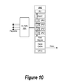
- This processor consists of only a single VS 1002 and an I/O 1004 .
- This configuration may function as, e.g., a PDA.
- FIG. 11A illustrates the integration of optical interfaces into a chip package of a processor of network 104 .
- These optical interfaces convert optical signals to electrical signals and electrical signals to optical signals and can be constructed from a variety of materials including, e.g., gallium arsinide, aluminum gallium arsinide, germanium and other elements or compounds.
- optical interfaces 1104 and 1106 are fabricated on the chip package of BE 1102 .
- BE bus 1108 provides communication among the PUs of BE 1102 , namely, PE 1110 , PE 1112 , PE 1114 , PE 1116 , and these optical interfaces.
- Optical interface 1104 includes two ports, namely, port 1118 and port 1120
- optical interface 1106 also includes two ports, namely, port 1122 and port 1124 .
- Ports 1118 , 1120 , 1122 and 1124 are connected to, respectively, optical wave guides 1126 , 1128 , 1130 and 1132 .
- Optical signals are transmitted to and from BE 1102 through these optical wave guides via the ports of optical interfaces 1104 and 1106 .
- a plurality of BEs can be connected together in various configurations using such optical wave guides and the four optical ports of each BE.
- two or more BEs e.g., BE 1152 , BE 1154 and BE 1156
- BE 1152 , BE 1154 and BE 1156 can be connected serially through such optical ports.
- optical interface 1166 of BE 1152 is connected through its optical ports to the optical ports of optical interface 1160 of BE 1154 .
- the optical ports of optical interface 1162 on BE 1154 are connected to the optical ports of optical interface 1164 of BE 1156 .
- FIG. 11C A matrix configuration is illustrated in FIG. 11C .
- the optical interface of each BE is connected to two other BEs.
- one of the optical ports of optical interface 1188 of BE 1172 is connected to an optical port of optical interface 1182 of BE 1176 .
- the other optical port of optical interface 1188 is connected to an optical port of optical interface 1184 of BE 1178 .
- one optical port of optical interface 1190 of BE 1174 is connected to the other optical port of optical interface 1184 of BE 1178 .
- the other optical port of optical interface 1190 is connected to an optical port of optical interface 1186 of BE 1180 .
- This matrix configuration can be extended in a similar manner to other BEs.
- a processor for network 104 can be constructed of any desired size and power.
- additional ports can be added to the optical interfaces of the BEs, or to processors having a greater or lesser number of PUs than a BE, to form other configurations.
- FIG. 12A illustrates the control system and structure for the DRAM of a BE.
- a similar control system and structure is employed in processors having other sizes and containing more or less PUs.
- a cross-bar switch connects each DMAC 1210 of the four PUs comprising BE 1201 to eight bank controls 1206 .
- Each bank control 1206 controls eight banks 1208 (only four are shown in the figure) of DRAM 1204 .
- DRAM 1204 therefore, comprises a total of sixty-four banks.
- DRAM 1204 has a capacity of 64 megabytes, and each bank has a capacity of 1 megabyte.
- the smallest addressable unit within each bank in this preferred embodiment, is a block of 1024 bits.
- BE 1201 also includes switch unit 1212 .
- Switch unit 1212 enables other SPUs on BEs closely coupled to BE 1201 to access DRAM 1204 .
- a second BE therefore, can be closely coupled to a first BE, and each SPU of each BE can address twice the number of memory locations normally accessible to an SPU.
- the direct reading or writing of data from or to the DRAM of a first BE from or to the DRAM of a second BE can occur through a switch unit such as switch unit 1212 .
- the SPU of a first BE e.g., SPU 1220 of BE 1222
- issues a write command to a memory location of a DRAM of a second BE e.g., DRAM 1228 of BE 1226 (rather than, as in the usual case, to DRAM 1224 of BE 1222 ).
- DMAC 1230 of BE 1222 sends the write command through cross-bar switch 1221 to bank control 1234 , and bank control 1234 transmits the command to an external port 1232 connected to bank control 1234 .
- DMAC 1238 of BE 1226 receives the write command and transfers this command to switch unit 1240 of BE 1226 .
- Switch unit 1240 identifies the DRAM address contained in the write command and sends the data for storage in this address through bank control 1242 of BE 1226 to bank 1244 of DRAM 1228 .
- Switch unit 1240 therefore, enables both DRAM 1224 and DRAM 1228 to function as a single memory space for the SPUs of BE 1226 .
- FIG. 13 shows the configuration of the sixty-four banks of a DRAM. These banks are arranged into eight rows, namely, rows 1302 , 1304 , 1306 , 1308 , 1310 , 1312 , 1314 and 1316 and eight columns, namely, columns 1320 , 1322 , 1324 , 1326 , 1328 , 1330 , 1332 and 1334 . Each row is controlled by a bank controller. Each bank controller, therefore, controls eight megabytes of memory.
- FIGS. 14A and 14B illustrate different configurations for storing and accessing the smallest addressable memory unit of a DRAM, e.g., a block of 1024 bits.
- DMAC 1402 stores in a single bank 1404 eight 1024 bit blocks 1406 .
- FIG. 14B shows that while DMAC 1412 reads and writes blocks of data containing 1024 bits, these blocks are interleaved between two banks, namely, bank 1414 and bank 1416 . Each of these banks, therefore, contains sixteen blocks of data, and each block of data contains 512 bits. This interleaving can facilitate faster accessing of the DRAM and is useful in the processing of certain applications.
- FIG. 15 illustrates the architecture for a DMAC 1504 within a PE.
- the structural hardware comprising DMAC 1506 is distributed throughout the PE such that each SPU 1502 has direct access to a structural node 1504 of DMAC 1506 .
- Each node executes the logic appropriate for memory accesses by the SPU to which the node has direct access.
- FIG. 16 shows an alternative embodiment of the DMAC, namely, a non-distributed architecture.
- the structural hardware of DMAC 1606 is centralized.
- SPUs 1602 and PU 1604 communicate with DMAC 1606 via local PE bus 1607 .
- DMAC 1606 is connected through a cross-bar switch to a bus 1608 .
- Bus 1608 is connected to DRAM 1610 .
- all of the multiple SPUs of a PU can independently access data in the shared DRAM.
- a first SPU could be operating upon particular data in its local storage at a time during which a second SPU requests these data. If the data were provided to the second SPU at that time from the shared DRAM, the data could be invalid because of the first SPU's ongoing processing which could change the data's value. If the second processor received the data from the shared DRAM at that time, therefore, the second processor could generate an erroneous result. For example, the data could be a specific value for a global variable. If the first processor changed that value during its processing, the second processor would receive an outdated value.
- a scheme is necessary, therefore, to synchronize the SPUs' reading and writing of data from and to memory locations within the shared DRAM. This scheme must prevent the reading of data from a memory location upon which another SPU currently is operating in its local storage and, therefore, which are not current, and the writing of data into a memory location storing current data.
- an additional segment of memory is allocated in the DRAM for storing status information relating to the data stored in the memory location.
- This status information includes a full/empty (F/E) bit, the identification of an SPU (SPU ID) requesting data from the memory location and the address of the SPU's local storage (LS address) to which the requested data should be read.
- An addressable memory location of the DRAM can be of any size. In a preferred embodiment, this size is 1024 bits.
- the setting of the F/E bit to 1 indicates that the data stored in the associated memory location are current.
- the setting of the F/E bit to 0, indicates that the data stored in the associated memory location are not current. If an SPU requests the data when this bit is set to 0, the SPU is prevented from immediately reading the data. In this case, an SPU ID identifying the SPU requesting the data, and an LS address identifying the memory location within the local storage of this SPU to which the data are to be read when the data become current, are entered into the additional memory segment.
- An additional memory segment also is allocated for each memory location within the local storage of the SPUs.
- This additional memory segment stores one bit, designated the “busy bit.”
- the busy bit is used to reserve the associated LS memory location for the storage of specific data to be retrieved from the DRAM. If the busy bit is set to 1 for a particular memory location in local storage, the SPU can use this memory location only for the writing of these specific data. On the other hand, if the busy bit is set to 0 for a particular memory location in local storage, the SPU can use this memory location for the writing of any data.
- FIGS. 17-31 Examples of the manner in which the F/E bit, the SPU ID, the LS address and the busy bit are used to synchronize the reading and writing of data from and to the shared DRAM of a PU are illustrated in FIGS. 17-31 .
- PE 1720 interacts with DRAM 1702 .
- PE 1720 includes SPU 1722 and SPU 1740 .
- SPU 1722 includes control logic 1724
- SPU 1740 includes control logic 1742 .
- SPU 1722 also includes local storage 1726 .
- This local storage includes a plurality of addressable memory locations 1728 .
- SPU 1740 includes local storage 1744 , and this local storage also includes a plurality of addressable memory locations 1746 . All of these addressable memory locations preferably are 1024 bits in size.
- An additional segment of memory is associated with each LS addressable memory location.
- memory segments 1729 and 1734 are associated with, respectively, local memory locations 1731 and 1732
- memory segment 1752 is associated with local memory location 1750 .
- a “busy bit,” as discussed above, is stored in each of these additional memory segments.
- Local memory location 1732 is shown with several Xs to indicate that this location contains data.
- DRAM 1702 contains a plurality of addressable memory locations 1704 , including memory locations 1706 and 1708 . These memory locations preferably also are 1024 bits in size. An additional segment of memory also is associated with each of these memory locations. For example, additional memory segment 1760 is associated with memory location 1706 , and additional memory segment 1762 is associated with memory location 1708 . Status information relating to the data stored in each memory location is stored in the memory segment associated with the memory location. This status information includes, as discussed above, the F/E bit, the SPU ID and the LS address. For example, for memory location 1708 , this status information includes F/E bit 1712 , SPU ID 1714 and LS address 1716 .
- the synchronized reading and writing of data from and to the shared DRAM among the SPUs of a PU, or a group of PUs, can be achieved.
- FIG. 18 illustrates the initiation of the synchronized writing of data from LS memory location 1732 of SPU 1722 to memory location 1708 of DRAM 1702 .
- Control 1724 of SPU 1722 initiates the synchronized writing of these data. Since memory location 1708 is empty, F/E bit 1712 is set to 0. As a result, the data in LS location 1732 can be written into memory location 1708 . If this bit were set to 1 to indicate that memory location 1708 is full and contains current, valid data, on the other hand, control 1722 would receive an error message and be prohibited from writing data into this memory location.
- FIG. 19 The result of the successful synchronized writing of the data into memory location 1708 is shown in FIG. 19 .
- the written data are stored in memory location 1708 , and F/E bit 1712 is set to 1. This setting indicates that memory location 1708 is full and that the data in this memory location are current and valid.
- FIG. 20 illustrates the initiation of the synchronized reading of data from memory location 1708 of DRAM 1702 to LS memory location 1750 of local storage 1744 .
- the busy bit in memory segment 1752 of LS memory location 1750 is set to 1 to reserve this memory location for these data.
- the setting of this busy bit to 1 prevents SPU 1740 from storing other data in this memory location.
- control logic 1742 next issues a synchronize read command for memory location 1708 of DRAM 1702 . Since F/E bit 1712 associated with this memory location is set to 1, the data stored in memory location 1708 are considered current and valid. As a result, in preparation for transferring the data from memory location 1708 to LS memory location 1750 , F/E bit 1712 is set to 0. This setting is shown in FIG. 22 . The setting of this bit to 0 indicates that, following the reading of these data, the data in memory location 1708 will be invalid.
- FIG. 23 shows the data within memory location 1708 next are read from memory location 1708 to LS memory location 1750 .
- FIG. 24 shows the final state.
- a copy of the data in memory location 1708 is stored in LS memory location 1750 .
- F/E bit 1712 is set to 0 to indicate that the data in memory location 1708 are invalid. This invalidity is the result of alterations to these data to be made by SPU 1740 .
- the busy bit in memory segment 1752 also is set to 0. This setting indicates that LS memory location 1750 now is available to SPU 1740 for any purpose, i.e., this LS memory location no longer is in a reserved state waiting for the receipt of specific data. LS memory location 1750 , therefore, now can be accessed by SPU 1740 for any purpose.
- FIGS. 25-31 illustrate the synchronized reading of data from a memory location of DRAM 1702 , e.g., memory location 1708 , to an LS memory location of an SPU's local storage, e.g., LS memory location 1752 of local storage 1744 , when the F/E bit for the memory location of DRAM 1702 is set to 0 to indicate that the data in this memory location are not current or valid.
- the busy bit in memory segment 1752 of LS memory location 1750 is set to 1 to reserve this LS memory location for this transfer of data.
- control logic 1742 next issues a synchronize read command for memory location 1708 of DRAM 1702 . Since the F/E bit associated with this memory location, F/E bit 1712 , is set to 0, the data stored in memory location 1708 are invalid. As a result, a signal is transmitted to control logic 1742 to block the immediate reading of data from this memory location.
- the SPU ID 1714 and LS address 1716 for this read command next are written into memory segment 1762 .
- the SPU ID for SPU 1740 and the LS memory location for LS memory location 1750 are written into memory segment 1762 .
- this SPU ID and LS memory location are used for determining the location to which the current data are to be transmitted.
- the data in memory location 1708 become valid and current when an SPU writes data into this memory location.
- This figure shows the valid data from memory location 1708 copied to memory location 1750 , the busy bit in memory segment 1752 set to 0 and F/E bit 1712 in memory segment 1762 set to 0.
- the setting of this busy bit to 0 enables LS memory location 1750 now to be accessed by SPU 1740 for any purpose.
- the setting of this F/E bit to 0 indicates that the data in memory location 1708 no longer are current and valid.
- FIG. 32 summarizes the operations described above and the various states of a memory location of the DRAM based upon the states of the F/E bit, the SPU ID and the LS address stored in the memory segment corresponding to the memory location.
- the memory location can have three states. These three states are an empty state 3280 in which the F/E bit is set to 0 and no information is provided for the SPU ID or the LS address, a full state 3282 in which the F/E bit is set to 1 and no information is provided for the SPU ID or LS address and a blocking state 3284 in which the F/E bit is set to 0 and information is provided for the SPU ID and LS address.
- a synchronized writing operation is permitted and results in a transition to full state 3282 .
- a synchronized reading operation results in a transition to the blocking state 3284 because the data in the memory location, when the memory location is in the empty state, are not current.
- full state 3282 a synchronized reading operation is permitted and results in a transition to empty state 3280 .
- a synchronized writing operation in full state 3282 is prohibited to prevent overwriting of valid data. If such a writing operation is attempted in this state, no state change occurs and an error message is transmitted to the SPU's corresponding control logic.
- blocking state 3284 the synchronized writing of data into the memory location is permitted and results in a transition to empty state 3280 .
- a synchronized reading operation in blocking state 3284 is prohibited to prevent a conflict with the earlier synchronized reading operation which resulted in this state. If a synchronized reading operation is attempted in blocking state 3284 , no state change occurs and an error message is transmitted to the SPU's corresponding control logic.
- the scheme described above for the synchronized reading and writing of data from and to the shared DRAM also can be used for eliminating the computational resources normally dedicated by a processor for reading data from, and writing data to, external devices.
- This input/output (I/O) function could be performed by a PU.
- an SPU running an appropriate program can perform this function. For example, using this scheme, a PU receiving an interrupt request for the transmission of data from an I/O interface initiated by an external device can delegate the handling of this request to this SPU. The SPU then issues a synchronize write command to the I/O interface. This interface in turn signals the external device that data now can be written into the DRAM.
- the SPU next issues a synchronize read command to the DRAM to set the DRAM's relevant memory space into a blocking state.
- the SPU also sets to 1 the busy bits for the memory locations of the SPU's local storage needed to receive the data.
- the additional memory segments associated with the DRAM's relevant memory space contain the SPU's ID and the address of the relevant memory locations of the SPU's local storage.
- the external device next issues a synchronize write command to write the data directly to the DRAM's relevant memory space. Since this memory space is in the blocking state, the data are immediately read out of this space into the memory locations of the SPU's local storage identified in the additional memory segments. The busy bits for these memory locations then are set to 0. When the external device completes writing of the data, the SPU issues a signal to the PU that the transmission is complete.
- the DRAM of each PU includes a plurality of “sandboxes.”
- a sandbox defines an area of the shared DRAM beyond which a particular SPU, or set of SPUs, cannot read or write data.
- These sandboxes provide security against the corruption of data being processed by one SPU by data being processed by another SPU.
- These sandboxes also permit the downloading of software cells from network 104 into a particular sandbox without the possibility of the software cell corrupting data throughout the DRAM.
- the sandboxes are implemented in the hardware of the DRAMs and DMACs. By implementing these sandboxes in this hardware rather than in software, advantages in speed and security are obtained.
- each entry in key control table 3302 contains an identification (ID) 3304 for an SPU, an SPU key 3306 for that SPU and a key mask 3308 .
- ID an identification
- SRAM static random access memory
- Key control table 3302 preferably is stored in a relatively fast memory, such as a static random access memory (SRAM), and is associated with the DMAC.
- SRAM static random access memory
- a dedicated memory segment 3410 is assigned to each addressable storage location 3406 of a DRAM 3402 .
- a memory access key 3412 for the storage location is stored in this dedicated memory segment.
- a further additional dedicated memory segment 3408 also associated with each addressable storage location 3406 , stores synchronization information for writing data to, and reading data from, the storage-location.
- an SPU issues a DMA command to the DMAC.
- This command includes the address of a storage location 3406 of DRAM 3402 .
- the DMAC looks up the requesting SPU's key 3306 in key control table 3302 using the SPU's ID 3304 .
- the DMAC compares the SPU key 3306 of the requesting SPU to the memory access key 3412 stored in the dedicated memory segment 3410 associated with the storage location of the DRAM to which the SPU seeks access. If the two keys do not match, the DMA command is not executed. On the other hand, if the two keys match, the DMA command proceeds and the requested memory access is executed.
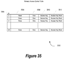
- FIG. 35 An alternative embodiment is illustrated in FIG. 35 .
- the PU also maintains a memory access control table 3502 .
- Memory access control table 3502 contains an entry for each sandbox within the DRAM.
- the DRAM contains 64 sandboxes.
- Each entry in memory access control table 3502 contains an identification (ID) 3504 for a sandbox, a base memory address 3506 , a sandbox size 3508 , a memory access key 3510 and an access key mask 3512 .
- Base memory address 3506 provides the address in the DRAM which starts a particular memory sandbox.
- Sandbox size 3508 provides the size of the sandbox and, therefore, the endpoint of the particular sandbox.
- FIG. 36 is a flow diagram of the steps for executing a DMA command using key control table 3302 and memory access control table 3502 .
- an SPU issues a DMA command to the DMAC for access to a particular memory location or locations within a sandbox.
- This command includes a sandbox ID 3504 identifying the particular sandbox for which access is requested.
- the DMAC looks up the requesting SPU's key 3306 in key control table 3302 using the SPU's ID 3304 .
- the DMAC uses the sandbox ID 3504 in the command to look up in memory access control table 3502 the memory access key 3510 associated with that sandbox.
- step 3608 the DMAC compares the SPU key 3306 assigned to the requesting SPU to the access key 3510 associated with the sandbox.
- step 3610 a determination is made of whether the two keys match. If the two keys do not match, the process moves to step 3612 where the DMA command does not proceed and an error message is sent to either the requesting SPU, the PU or both. On the other hand, if at step 3610 the two keys are found to match, the process proceeds to step 3614 where the DMAC executes the DMA command.
- a key mask for a key converts a masked bit into a wildcard. For example, if the key mask 3308 associated with an SPU key 3306 has its last two bits set to “mask,” designated by, e.g., setting these bits in key mask 3308 to 1, the SPU key can be either a 1 or a 0 and still match the memory access key. For example, the SPU key might be 1010. This SPU key normally allows access only to a sandbox having an access key of 1010.
- SPU key mask for this SPU key is set to 0001, however, then this SPU key can be used to gain access to sandboxes having an access key of either 1010 or 1011.
- an access key 1010 with a mask set to 0001 can be accessed by an SPU with an SPU key of either 1010 or 1011. Since both the SPU key mask and the memory key mask can be used simultaneously, numerous variations of accessibility by the SPUs to the sandboxes can be established.
- the present invention also provides a new programming model for the processors of system 101 .
- This programming model employs software cells 102 . These cells can be transmitted to any processor on network 104 for processing.
- This new programming model also utilizes the unique modular architecture of system 101 and the processors of system 101 .
- Software cells are processed directly by the SPUs from the SPU's local storage.
- the SPUs do not directly operate on any data or programs in the DRAM. Data and programs in the DRAM are read into the SPU's local storage before the SPU processes these data and programs.
- the SPU's local storage therefore, includes a program counter, stack and other software elements for executing these programs.
- the PU controls the SPUs by issuing direct memory access (DMA) commands to the DMAC.
- DMA direct memory access
- a software cell e.g., software cell 3702
- the information contained in routing information section 3704 is dependent upon the protocol of network 104 .
- Routing information section 3704 contains header 3708 , destination ID 3710 , source ID 3712 and reply ID 3714 .
- the destination ID includes a network address. Under the TCP/IP protocol, e.g., the network address is an Internet protocol (IP) address.
- Destination ID 3710 further includes the identity of the PU and SPU to which the cell should be transmitted for processing.
- Source ID 3712 contains a network address and identifies the PU and SPU from which the cell originated to enable the destination PU and SPU to obtain additional information regarding the cell if necessary.
- Reply ID 3714 contains a network address and identifies the PU and SPU to which queries regarding the cell, and the result of processing of the cell, should be directed.
- Cell body 3706 contains information independent of the network's protocol. The exploded portion of FIG. 37 shows the details of cell body 3706 . Header 3720 of cell body 3706 identifies the start of the cell body. Cell interface 3722 contains information necessary for the cell's utilization. This information includes global unique ID 3724 , required SPUs 3726 , sandbox size 3728 and previous cell ID 3730 .
- Global unique ID 3724 uniquely identifies software cell 3702 throughout network 104 .
- Global unique ID 3724 is generated on the basis of source ID 3712 , e.g. the unique identification of a PU or SPU within source ID 3712 , and the time and date of generation or transmission of software cell 3702 .
- Required SPUs 3726 provides the minimum number of SPUs required to execute the cell.
- Sandbox size 3728 provides the amount of protected memory in the required SPUs' associated DRAM necessary to execute the cell.
- Previous cell ID 3730 provides the identity of a previous cell in a group of cells requiring sequential execution, e.g., streaming data.
- Implementation section 3732 contains the cell's core information. This information includes DMA command list 3734 , programs 3736 and data 3738 .
- Programs 3736 contain the programs to be run by the SPUs (called “spulets”)), e.g., SPU programs 3760 and 3762 , and data 3738 contain the data to be processed with these programs.
- DMA command list 3734 contains a series of DMA commands needed to start the programs. These DMA commands include DMA commands 3740 , 3750 , 3755 and 3758 . The PU issues these DMA commands to the DMAC.
- DMA command 3740 includes VID 3742 .
- VID 3742 is the virtual ID of an SPU which is mapped to a physical ID when the DMA commands are issued.
- DMA command 3740 also includes load command 3744 and address 3746 .
- Load command 3744 directs the SPU to read particular information from the DRAM into local storage.
- Address 3746 provides the virtual address in the DRAM containing this information. The information can be, e.g., programs from programs section 3736 , data from data section 3738 or other data.
- DMA command 3740 includes local storage address 3748 . This address identifies the address in local storage where the information should be loaded.
- DMA commands 3750 contain similar information. Other DMA commands are also possible.
- DMA command list 3734 also includes a series of kick commands, e.g., kick commands 3755 and 3758 .
- Kick commands are commands issued by a PU to an SPU to initiate the processing of a cell.
- DMA kick command 3755 includes virtual SPU ID 3752 , kick command 3754 and program counter 3756 .
- Virtual SPU ID 3752 identifies the SPU to be kicked
- kick command 3754 provides the relevant kick command
- program counter 3756 provides the address for the program counter for executing the program.
- DMA kick command 3758 provides similar information for the same SPU or another SPU.
- the PUs treat the SPUs as independent processors, not co-processors. To control processing by the SPUs, therefore, the PU uses commands analogous to remote procedure calls. These commands are designated “SPU Remote Procedure Calls” (SRPCs).
- SRPCs SPU Remote Procedure Calls
- a PU implements an SRPC by issuing a series of DMA commands to the DMAC.
- the DMAC loads the SPU program and its associated stack frame into the local storage of an SPU.
- the PU then issues an initial kick to the SPU to execute the SPU Program.
- FIG. 38 illustrates the steps of an SRPC for executing an spulet.
- the steps performed by the PU in initiating processing of the spulet by a designated SPU are shown in the first portion 3802 of FIG. 38
- the steps performed by the designated SPU in processing the spulet are shown in the second portion 3804 of FIG. 38 .
- step 3810 the PU evaluates the spulet and then designates an SPU for processing the spulet.
- the PU allocates space in the DRAM for executing the spulet by issuing a DMA command to the DMAC to set memory access keys for the necessary sandbox or sandboxes.
- the PU enables an interrupt request for the designated SPU to signal completion of the spulet.
- the PU issues a DMA command to the DMAC to load the spulet from the DRAM to the local storage of the SPU.
- step 3820 the DMA command is executed, and the spulet is read from the DRAM to the SPU's local storage.
- step 3822 the PU issues a DMA command to the DMAC to load the stack frame associated with the spulet from the DRAM to the SPU's local storage.
- step 3823 the DMA command is executed, and the stack frame is read from the DRAM to the SPU's local storage.
- step 3824 the PU issues a DMA command for the DMAC to assign a key to the SPU to allow the SPU to read and write data from and to the hardware sandbox or sandboxes designated in step 3812 .
- step 3826 the DMAC updates the key control table (KTAB) with the key assigned to the SPU.
- step 3828 the PU issues a DMA command “kick” to the SPU to start processing of the program.
- Other DMA commands may be issued by the PU in the execution of a particular SRPC depending upon the particular spulet.
- second portion 3804 of FIG. 38 illustrates the steps performed by the SPU in executing the spulet.
- the SPU begins to execute the spulet in response to the kick command issued at step 3828 .
- the SPU at the direction of the spulet, evaluates the spulet's associated stack frame.
- the SPU issues multiple DMA commands to the DMAC to load data designated as needed by the stack frame from the DRAM to the SPU's local storage.
- these DMA commands are executed, and the data are read from the DRAM to the SPU's local storage.
- step 3838 the SPU executes the spulet and generates a result.
- step 3840 the SPU issues a DMA command to the DMAC to store the result in the DRAM.
- step 3842 the DMA command is executed and the result of the spulet is written from the SPU's local storage to the DRAM.
- step 3844 the SPU issues an interrupt request to the PU to signal that the SRPC has been completed.
- SPUs to perform tasks independently under the direction of a PU
- a PU can dedicate a group of SPUs, and the memory resources associated with a group of SPUs, to performing extended tasks.
- a PU can dedicate one or more SPUs, and a group of memory sandboxes associated with these one or more SPUs, to receiving data transmitted over network 104 over an extended period and to directing the data received during this period to one or more other SPUs and their associated memory sandboxes for further processing.
- This ability is particularly advantageous to processing streaming data transmitted over network 104 , e.g., streaming MPEG or streaming ATRAC audio or video data.
- a PU can dedicate one or more SPUs and their associated memory sandboxes to receiving these data and one or more other SPUs and their associated memory sandboxes to decompressing and further processing these data.
- the PU can establish a dedicated pipeline relationship among a group of SPUs and their associated memory sandboxes for processing such data.
- the pipeline's dedicated SPUs and memory sandboxes should remain dedicated to the pipeline during periods in which processing of spulets comprising the data stream does not occur.
- the dedicated SPUs and their associated sandboxes should be placed in a reserved state during these periods.
- the reservation of an SPU and its associated memory sandbox or sandboxes upon completion of processing of an spulet is called a “resident termination.”
- a resident termination occurs in response to an instruction from a PU.
- FIGS. 39 , 40 A and 40 B illustrate the establishment of a dedicated pipeline structure comprising a group of SPUs and their associated sandboxes for the processing of streaming data, e.g., streaming MPEG data.
- the components of this pipeline structure include PE 3902 and DRAM 3918 .
- PE 3902 includes PU 3904 , DMAC 3906 and a plurality of SPUs, including SPU 3908 , SPU 3910 and SPU 3912 . Communications among PU 3904 , DMAC 3906 and these SPUs occur through PE bus 3914 .
- Wide bandwidth bus 3916 connects DMAC 3906 to DRAM 3918 .
- DRAM 3918 includes a plurality of sandboxes, e.g., sandbox 3920 , sandbox 3922 , sandbox 3924 and sandbox 3926 .
- FIG. 40A illustrates the steps for establishing the dedicated pipeline.
- PU 3904 assigns SPU 3908 to process a network spulet.
- a network spulet comprises a program for processing the network protocol of network 104 .
- this protocol is the Transmission Control Protocol/Internet Protocol (TCP/IP).
- TCP/IP data packets conforming to this protocol are transmitted over network 104 .
- SPU 3908 processes these packets and assembles the data in the packets into software cells 102 .
- PU 3904 instructs SPU 3908 to perform resident terminations upon the completion of the processing of the network spulet.
- step 4014 PU 3904 assigns PUs 3910 and 3912 to process MPEG spulets.
- step 4015 PU 3904 instructs SPUs 3910 and 3912 also to perform resident terminations upon the completion of the processing of the MPEG spulets.
- step 4016 PU 3904 designates sandbox 3920 as a source sandbox for access by SPU 3908 and SPU 3910 .
- step 4018 PU 3904 designates sandbox 3922 as a destination sandbox for access by SPU 3910 .
- step 4020 PU 3904 designates sandbox 3924 as a source sandbox for access by SPU 3908 and SPU 3912 .
- step 4022 PU 3904 designates sandbox 3926 as a destination sandbox for access by SPU 3912 .
- step 4024 SPU 3910 and SPU 3912 send synchronize read commands to blocks of memory within, respectively, source sandbox 3920 and source sandbox 3924 to set these blocks of memory into the blocking state.
- step 4028 establishment of the dedicated pipeline is complete and the resources dedicated to the pipeline are reserved.
- SPUs 3908 , 3910 and 3912 and their associated sandboxes 3920 , 3922 , 3924 and 3926 therefore, enter the reserved state.
- FIG. 40B illustrates the steps for processing streaming MPEG data by this dedicated pipeline.
- SPU 3908 which processes the network spulet, receives in its local storage TCP/IP data packets from network 104 .
- SPU 3908 processes these TCP/IP data packets and assembles the data within these packets into software cells 102 .
- SPU 3908 examines header 3720 ( FIG. 37 ) of the software cells to determine whether the cells contain MPEG data. If a cell does not contain MPEG data, then, in step 4036 , SPU 3908 transmits the cell to a general purpose sandbox designated within DRAM 3918 for processing other data by other SPUs not included within the dedicated pipeline. SPU 3908 also notifies PU 3904 of this transmission.
- SPU 3908 examines previous cell ID 3730 ( FIG. 37 ) of the cell to identify the MPEG data stream to which the cell belongs.
- SPU 3908 chooses an SPU of the dedicated pipeline for processing of the cell.
- SPU 3908 chooses SPU 3910 to process these data. This choice is based upon previous cell ID 3730 and load balancing factors. For example, if previous cell ID 3730 indicates that the previous software cell of the MPEG data stream to which the software cell belongs was sent to SPU 3910 for processing, then the present software cell normally also will be sent to SPU 3910 for processing.
- step 4042 SPU 3908 issues a synchronize write command to write the MPEG data to sandbox 3920 . Since this sandbox previously was set to the blocking state, the MPEG data, in step 4044 , automatically is read from sandbox 3920 to the local storage of SPU 3910 .
- step 4046 SPU 3910 processes the MPEG data in its local storage to generate video data.
- step 4048 SPU 3910 writes the video data to sandbox 3922 .
- step 4050 SPU 3910 issues a synchronize read command to sandbox 3920 to prepare this sandbox to receive additional MPEG data.
- step 4052 SPU 3910 processes a resident termination. This processing causes this SPU to enter the reserved state during which the SPU waits to process additional MPEG data in the MPEG data stream.
- a dedicated group of SPUs e.g., SPUs 4102 , 4108 and 4114
- SPUs 4102 , 4108 and 4114 can be established for performing geometric transformations upon three dimensional objects to generate two dimensional display lists. These two dimensional display lists can be further processed (rendered) by other SPUs to generate pixel data.
- sandboxes are dedicated to SPUs 4102 , 4108 and 4114 for storing the three dimensional objects and the display lists resulting from the processing of these objects.
- source sandboxes 4104 , 4110 and 4116 are dedicated to storing the three dimensional objects processed by, respectively, SPU 4102 , SPU 4108 and SPU 4114 .
- destination sandboxes 4106 , 4112 and 4118 are dedicated to storing the display lists resulting from the processing of these three dimensional objects by, respectively, SPU 4102 , SPU 4108 and SPU 4114 .
- Coordinating SPU 4120 is dedicated to receiving in its local storage the display lists from destination sandboxes 4106 , 4112 and 4118 . SPU 4120 arbitrates among these display lists and sends them to other SPUs for the rendering of pixel data.
- the processors of system 101 also employ an absolute timer.
- the absolute timer provides a clock signal to the SPUs and other elements of a PU which is both independent of, and faster than, the clock signal driving these elements.
- the use of this absolute timer is illustrated in FIG. 42 .
- the absolute timer establishes a time budget for the performance of tasks by the SPUs.
- This time budget provides a time for completing these tasks which is longer than that necessary for the SPUs' processing of the tasks.
- a busy period As a result, for each task, there is, within the time budget, a busy period and a standby period. All spulets are written for processing on the basis of this time budget regardless of the SPUs' actual processing time or speed.
- a particular task may be performed during busy period 4202 of time budget 4204 . Since busy period 4202 is less than time budget 4204 , a standby period 4206 occurs during the time budget. During this standby period, the SPU goes into a sleep mode during which less power is consumed by the SPU.
- the results of processing a task are not expected by other SPUs, or other elements of a PU, until a time budget 4204 expires. Using the time budget established by the absolute timer, therefore, the results of the SPUs' processing always are coordinated regardless of the SPUs' actual processing speeds.
- the PU can analyze the particular instructions or microcode being executed by an SPU in processing an spulet for problems in the coordination of the SPUs' parallel processing created by enhanced or different operating speeds.
- NOOP No operation
- instructions can be inserted into the instructions and executed by some of the SPUs to maintain the proper sequential completion of processing by the SPUs expected by the spulet. By inserting these NOOPs into the instructions, the correct timing for the SPUs' execution of all instructions can be maintained.
- FIG. 43 is a diagram showing a processing unit initiating a program and the program's runtime loader loading dependent files onto a synergistic processing unit.
- a computer system includes Processing Unit (PU) 4300 and Synergistic Processing Unit (SPU) 4350 .
- PU 4300 boots-up and initializes the computer system during which time PU 4300 loads an operating system.
- the operating system performs basic tasks, such as recognizing input from a keyboard, sending output to a display screen, keeping track of files and directories on a disk, and controlling peripheral devices, such as disk drives and printers.
- the operating system includes a kernel, such as kernel 4320 . Kernel 4320 is a central module of the operating system which loads, and remains, in memory 4325 . Memory 4325 is PU 4300 's local memory area. Kernel 4320 is responsible for memory management, process and task management, and disk management.
- Kernel 4320 loads PU program 4312 into memory 4325 which is an program that is executed by PU 4300 .
- kernel 4320 identifies runtime loader 4315 which corresponds to PU program 4312 .
- Runtime loader 4315 is responsible for loading objects, resolving symbols, and loading other files (i.e. data, programs) that correspond to PU program 4312 .
- Kernel 4320 loads runtime loader 4315 into memory 4325 and passes control to runtime loader 4315 .
- Runtime loader 4315 starts to identify files that PU program 4320 depends, such as SPU file 4340 .
- Runtime loader loads SPU file 4340 into memory 4325 , and extracts a processor identifier from SPU file 4340 's header.
- SPU file 4340 may be an ELF formatted file in which case it includes a “machine type” in its ELF header which signifies which processor to be loaded (see FIGS. 47A , 47 B, and corresponding text for further details regarding header information).
- Runtime loader 4315 determines that SPU file 4340 should run on SPU 4350 based upon SPU file 4340 's processor identifier, and sends SPU file 4340 to SPU 4350 using a DMA command, such as DMA 4360 .
- SPU 4350 receives SPU file 4340 and stores it in memory 4370 .
- Memory 4370 is SPU 4350 's local memory area.
- SPU 4350 is now able to execute SPU file 4340 (see FIGS. 45 , 46 , and corresponding text for further details regarding code execution).
- FIG. 44 is a diagram showing a runtime loader receiving a combined file, extracting a Synergistic Processing Unit (SPU) file that is included in the combined file, and sending the SPU file to an SPU.
- FIG. 44 is similar to FIG. 43 except PU 4300 processes a combined file in FIG. 44 as opposed to a separate file as shown in FIG. 43 .
- Combined file 4400 is a combined executable program that contains both 32 bit (or 64 bit) PU code and SPU code (e.g. SPU file 4340 ).
- Combined file 4400 may also be viewed as having embedded SPU code in a PU executable program.
- Runtime loader 4315 loads combined file 4400 into memory 4325 .
- Runtime loader 4315 then analyzes combined file 4400 's file header to identify whether there is embedded code included in combined file 4400 which is targeted for SPU 4350 (see FIGS. 47A , 47 B, and corresponding text for further details regarding file headers).
- Runtime loader 4315 identifies SPU file 4340 from combined file 4400 's header information, and sends SPU file 4340 to memory 4370 using DMA 4430 .
- DMA 4430 provides a mechanism for PU 4300 to send data from its memory (e.g. memory 4325 ) directly to SPU 4350 's memory (e.g. memory 4370 ).
- SPU 4350 receives SPU file 4340 , SPU 4350 is ready to execute SPU file 4340 (see FIGS. 45 , 46 , and corresponding text for further details regarding code execution).
- FIG. 45 is a diagram showing a synergistic processing unit (SPU) file receiving a plug-in from a processing unit (PU) program.
- SPU 4350 received SPU file 4340 from PU 4300 while PU 4300 executes PU program 4512 (see FIGS. 43 , 44 , and corresponding text for further details regarding SPU file transmission).
- PU program 4512 is similar to PU program 4312 as shown in FIG. 43 and also similar to the PU executable portion of combined file 4400 shown in FIG. 44 .
- SPU file 4340 is an executable file which includes its own runtime loader, such as runtime loader 4530 . During SPU file 4340 's execution, runtime loader 4530 retrieves and loads files in which SPU file 4340 depends.
- SPU file 4340 may be a graphics program whereby it requires a plug-in module for manipulating data.
- Runtime loader 4530 recognizes that SPU file 4340 requires a plug-in, and sends request 4550 to PU program 4512 .
- PU program 4512 receives the request, and retrieves plug-in 4510 from system memory 4310 .
- System memory 4310 is the same as that shown in FIG. 43 .
- PU program 4512 sends plug-in 4510 to runtime loader 4530 using DMA 4560 which, in turn, runtime loader 4530 stores plug-in 4510 in memory 4370 for SPU file 4340 to access.
- SPU file 4340 may also receive data from PU program 4512 using the same technique as described above. When SPU file 4340 is finished processing data using plug-in 4510 , SPU file 4340 sends acknowledgment 4570 to PU 4300 which indicates that SPU 4350 is finished processing data. In one embodiment, acknowledgement 4570 may include processed data or may include a memory location reference where PU 4300 retrieves resultant data.
- FIG. 46 is a diagram showing a synergistic processing unit (SPU) independently retrieving a plug-in from system memory that corresponds to an SPU executable file.
- FIG. 46 is different than FIG. 45 in that SPU file 4340 independently retrieves plug-ins and/or data from system memory without the intervention of PU program 4512 .
- SPU 4350 received SPU file 4340 from PU 4300 while PU 4300 executes PU program 4512 (see FIGS. 43 , 44 , and corresponding text for further details regarding SPU file transmission).
- SPU file 4340 is an executable file which includes its own runtime loader, such as runtime loader 4530 .
- runtime loader 4530 retrieves and loads files in which SPU file 4340 depends.
- SPU file 4340 may be a graphics program whereby it requires a plug-in module for manipulating data.
- Runtime loader 4530 recognizes that SPU file 4340 requires a plug-in, such as plug-in 4510 , and identifies the location in system memory 4500 in which plug-in 4510 is located by checking a memory map that corresponds to system memory 4500 .
- SPU 4350 includes a memory management unit (MMU).
- MMU memory management unit
- DMA Direct Memory Access
- runtime loader 4530 retrieves plug-in 4510 from system memory 4500 using DMA 4640 , and loads plug-in 4510 into memory 4370 .
- SPU file 4340 uses plug-in 4510 to process data, and sends acknowledgement 4650 to PU program 4612 when complete.
- FIG. 47A is user code showing various code lines included in a combined file.
- a combined file is an executable program that contains both 32 bit (or 64 bit) PU code and SPU code (see FIG. 44 and corresponding text for further details regarding combined files).
- a combined file may also be interpreted as having embedded SPU code in a PU executable program.
- Code 4700 includes ELF header 4710 and section headers 4730 .
- ELF header 4710 includes code that is particular to the combined file and identifies which processor type the combined file should run.
- line 4720 includes a “PU” machine type which informs a runtime loader that the combined file should be loaded on a PU for processing.
- other file formats may be used such as Extended Common Object File Format (XCOFF) or Portable Executable Common Object File Format (PECOFF).
- Section headers 4730 include contents of embedded files.
- line 4740 includes an “.spuelf” program which is an SPU program that a runtime loader loads into an SPU's local store and is executed independently from the PU.
- a symbol may be included in the .spuelf file which provides access to the file when it is loaded and mapped into system memory.
- SPU code is loaded into system memory implicitly when referenced by PU code at link time.
- SPU code is loaded into system memory explicitly when it is dynamically determined to load SPU code.
- a symbol points to the SPU ELF image in system memory of an SPU program or plug-in. Since the PU code controls and initiates SPU activity, special APIs (Application Programming Interfaces) may be used which indicate that the SPU code located at a particular symbol (i.e. system memory address) should be loaded onto an SPU and executed.
- special APIs Application Programming Interfaces
- the SPU ELF image is parsed in memory, validated that it is an SPU ELF image using the ELF “machine type”, and then sent to an available SPU using a DMA execution.
- These APIs may be thought of as extensions to the runtime loader that are dynamically invoked when a PU program wishes to initiate SPU activity and load/execute SPU code.
- FIG. 47B is user code showing various code lines included in a dependent file. Since code 4750 is an independent file (i.e. not embedded), it does not require section headers as shown in FIG. 47A . Instead, ELF header 4760 includes a machine type, such as “SPU” included in line 4770 which informs a runtime loader that the independent program should be loaded onto an SPU.
- SPU machine type
- FIG. 48 is a flowchart showing steps taken in a processing unit (PU) executing a program and passing control to the program's runtime loader.
- PU processing commences at 4800 , whereupon the PU loads a kernel in the PU's memory, such as memory 4325 .
- the kernel retrieves an executable file from system memory 4310 , and loads the executable file in memory 4325 at step 4820 .
- System memory 4310 and memory 4325 are the same as that shown in FIG. 43 .
- the kernel retrieves a runtime loader from system memory 4310 that corresponds to the executable file, and loads the runtime loader in memory 4325 at step 4830 .
- the runtime loader is responsible for loading files that the executable file depends.
- the executable file may be a retirement prediction program and the runtime loader may load a dependent file such as an interest rate application.
- the kernel passes control to the runtime loader at step 4840 , whereupon the runtime loader retrieves a first dependent file from system memory 4310 at step 4850 .
- the runtime loader retrieves the interest rate application from system memory 4310 .
- the runtime loader loads the dependent file into memory 4325 at step 4860 .
- the dependent file includes a header, such as an ELF header, whereby the header includes a processor identifier, such as a machine type, that distinguishes which type of processor the dependent file should run (see FIG. 47A , 47 B, and corresponding text for further details regarding processor identifiers).
- the runtime loader extracts the dependent file's corresponding processor identifier at step 4865 .
- decision 4870 branches to “Yes” branch 4878 whereupon DMA steps are unnecessary since the dependent file is already loaded onto the PU's memory (e.g. memory 4325 ).
- FIG. 49 is a flowchart showing steps taken in a synergistic processing unit (SPU) receiving a file from a processing unit (PU) and executing the file. Processing commences at 4900 , whereupon the SPU receives a dependent file from PU 4300 and stores the file in memory 4370 (step 4910 ).
- PU 4300 is the same PU as that shown in FIG. 43 .
- Memory 4370 is the SPU's internal memory and is the same as that shown in FIG. 43 .
- the SPU executes the file and the file initiates a runtime loader at step 4935 .
- the runtime loader is responsible for loading objects, resolving symbols, and loading other files (i.e. data, programs) that correspond to the SPU's dependent file.
- the runtime loader identifies a plug-in and/or data that the dependent file requires at step 4938 .
- the dependent file may be a graphics application and the graphics application requires an edge smoothing plug-in.
- decision 4940 branches to “No” branch 4942 whereupon processing sends a request to PU 4300 requesting a particular plug-in or data (step 4945 ). Processing receives data and/or a plug in from PU 4300 , and stores it in memory 4370 at step 4950 .
- decision 4940 branches to “Yes” branch 4948 whereupon the SPU retrieves data and/or a plug-in from system memory 4310 and stores it in memory 4370 (step 4960 ). SPU processes the data at step 4970 , and sends an acknowledgement to PU 4300 at step 4980 .
- a determination is made as to whether to continue processing (decision 4990 ). For example, PU 4300 may request the SPU to continue to have a financial calculator loaded, waiting for user input, until the user exits from a particular user interface. If processing should continue, decision 4990 branches to “Yes” branch 4992 which loops back to process more data and/or load more plug-in's. This looping continues until the SPU should not continue processing data using the dependent file, at which point decision 4990 branches to “No” branch 4998 whereupon processing ends at 4999 .
- FIG. 50 is a block diagram illustrating a processing element having a main processor and a plurality of secondary processors sharing a system memory.
- Processor Element (PE) 5005 includes processing unit (PU) 5010 , which, in one embodiment, acts as the main processor and runs an operating system.
- Processing unit 5010 may be, for example, a Power PC core executing a Linux operating system.
- PE 5005 also includes a plurality of synergistic processing complex's (SPCs) such as SPCs 5045 , 5065 , and 5085 .
- the SPCs include synergistic processing units (SPUs) that act as secondary processing units to PU 5010 , a memory storage unit, and local storage.
- SPUs synergistic processing units
- SPC 5045 includes SPU 5060 , MMU 5055 , and local storage 5059 ;
- SPC 5065 includes SPU 5070 , MMU 5075 , and local storage 5079 ;
- SPC 5085 includes SPU 5090 , MMU 5095 , and local storage 5099 .
- Each SPC may be configured to perform a different task, and accordingly, in one embodiment, each SPC may be accessed using different instruction sets. If PE 5005 is being used in a wireless communications system, for example, each SPC may be responsible for separate processing tasks, such as modulation, chip rate processing, encoding, network interfacing, etc. In another embodiment, the SPCs may have identical instruction sets and may be used in parallel with each other to perform operations benefiting from parallel processing.
- PE 5005 may also include level 2 cache, such as L2 cache 5015 , for the use of PU 5010 .
- PE 5005 includes system memory 5020 , which is shared between PU 5010 and the SPUs.
- System memory 5020 may store, for example, an image of the running operating system (which may include the kernel), device drivers, I/O configuration, etc., executing applications, as well as other data.
- System memory 5020 includes the local storage units of one or more of the SPCs, which are mapped to a region of system memory 5020 . For example, local storage 5059 may be mapped to mapped region 5035 , local storage 5079 may be mapped to mapped region 5040 , and local storage 5099 may be mapped to mapped region 5042 .
- PU 5010 and the SPCs communicate with each other and system memory 5020 through bus 5017 that is configured to pass data between these devices.
- the MMUs are responsible for transferring data between an SPU's local store and the system memory.
- an MMU includes a direct memory access (DMA) controller configured to perform this function.
- PU 5010 may program the MMUs to control which memory regions are available to each of the MMUs. By changing the mapping available to each of the MMUs, the PU may control which SPU has access to which region of system memory 5020 . In this manner, the PU may, for example, designate regions of the system memory as private for the exclusive use of a particular SPU.
- the SPUs' local stores may be accessed by PU 5010 as well as by the other SPUs using the memory map.
- PU 5010 manages the memory map for the common system memory 5020 for all the SPUs.
- the memory map table may include PU 5010 's L2 Cache 5015 , system memory 5020 , as well as the SPUs' shared local stores.
- the SPUs process data under the control of PU 5010 .
- the SPUs may be, for example, digital signal processing cores, microprocessor cores, micro controller cores, etc., or a combination of the above cores.
- Each one of the local stores is a storage area associated with a particular SPU.
- each SPU can configure its local store as a private storage area, a shared storage area, or an SPU may configure its local store as a partly private and partly shared storage.
- an SPU may allocate 100% of its local store to private memory accessible only by that SPU. If, on the other hand, an SPU requires a minimal amount of local memory, the SPU may allocate 10% of its local store to private memory and the remaining 90% to shared memory.
- the shared memory is accessible by PU 5010 and by the other SPUs.
- An SPU may reserve part of its local store in order for the SPU to have fast, guaranteed memory access when performing tasks that require such fast access.
- the SPU may also reserve some of its local store as private when processing sensitive data, as is the case, for example, when the SPU is performing encryption/decryption.
- SPU code is loaded into system memory implicitly when referenced by PU code at link time.
- SPU code is loaded into system memory explicitly when it is dynamically determined to load SPU code.
- a symbol points to the SPU ELF image in system memory of an SPU program or plug-in. Since the PU code controls and initiates SPU activity, special APIs (Application Programming Interfaces) may be used which indicate that the SPU code located at a particular symbol (i.e. system memory address) should be loaded onto an SPU and executed. When one of these APIs is called, the SPU ELF image is parsed in memory, validated that it is an SPU ELF image using the ELF “machine type”, and then DMA'd onto an available SPU.
- These APIs may be thought of as extensions to the runtime loader that are dynamically invoked when a PU program wishes to initiate SPU activity and load/execute SPU code.
- One of the preferred implementations of the invention is an application, namely, a set of instructions (program code) in a code module which may, for example, be resident in the random access memory of the computer.
- the set of instructions may be stored in another computer memory, for example, on a hard disk drive, or in removable storage such as an optical disk (for eventual use in a CD ROM) or floppy disk (for eventual use in a floppy disk drive), or downloaded via the Internet or other computer network.
- the present invention may be implemented as a computer program product for use in a computer.
Abstract
Loading software on a plurality of processors is presented. A processing unit (PU) retrieves a file from system memory and loads it into its internal memory. The PU extracts a processor type from the file's header which identifies whether the file should execute on the PU or a synergistic processing unit (SPU). If an SPU should execute the file, the PU DMA's the file to the SPU for execution. In one embodiment, the file is a combined file which includes both PU and SPU code. In this embodiment, the PU identifies one or more section headers included in the file which indicates embedded SPU code within the combined file. In this embodiment, the PU extracts the SPU code from the combined file and DMA's the extracted code to an SPU for execution.
Description
This application is a continuation application of co-pending U.S. Non-Provisional patent application Ser. No. 10/670,842, entitled “Loading Software on a Plurality of Processors,” filed on Sep. 25, 2003.
1. Technical Field
The present invention relates in general to a system and method for loading software on a plurality of processors. More particularly, the present invention relates to a system and method for extracting a processor type from a file and loading the file on a processor that corresponds to the processor type.
2. Description of the Related Art
Computer systems are becoming more and more complex. The computer industry typically doubles the performance of a computer system every 18 months, such as personal computers, PDAs, and gaming consoles. In order for the computer industry to accomplish this task, the semiconductor industry produces integrated circuits that double in performance every 18 months. A computer system uses an integrated circuit for particular functions based upon the integrated circuit's architecture. Two fundamental architectures are 1) a microprocessor-based architecture and 2) a digital signal processor-based architecture.
An integrated circuit with a microprocessor-based architecture is typically used to handle control operations whereas an integrated circuit with a digital signal processor-based architecture is typically designed to handle signal-processing functions (i.e. mathematical operations). As technology evolves, the computer industry and the semiconductor industry are using both architectures, or processor types, in a computer system design.
Software is another element in a computer system that has been evolving alongside integrated circuit evolution. A software developer writes code in a manner that corresponds to the processor type that executes the code. For example, a processor has a particular number of registers and a particular number of arithmetic logic units (ALUs) whereby the software developer designs his code to most effectively use the registers and the ALUs.
As the semiconductor industry incorporates multiple processor types onto a single device, and as software developers write code to execute on multiple processor type architectures, a challenge found is identifying which files to load on a particular processor type.
Executable files typically employ a runtime loader which loads dependent files onto memory. The runtime loader, however, assumes that the same processor that is executing the runtime loader executes the dependent files. In a multi-processor environment, however, this may not be the case. In addition, in a heterogeneous processor environment, the code for a particular file is formatted for a particular processor type and may not run if the code is loaded on a different processor type.
What is needed, therefore, is a system and method for associating a processor type to a file and loading the file on a processor that corresponds to the associated processor type.
It has been discovered that the aforementioned challenges are resolved by extracting a processor identifier that is included in a file's header, and loading the file on a processor that corresponds to the extracted processor identifier.
A computer system includes a processing unit (PU) and a synergistic processing unit (SPU). The PU boots-up and initializes the computer system during which time the PU loads an operating system. The operating system performs basic tasks, such as recognizing input from a keyboard, sending output to a display screen, keeping track of files and directories on a disk, and controlling peripheral devices, such as disk drives and printers. The operating system includes a kernel that is a central module of the operating system and is responsible for memory management, process management, task management, and disk management.
The kernel loads a PU program into the PU's internal memory. During the loading process, the kernel identifies a runtime loader that corresponds to the PU program. The runtime loader is responsible for loading objects, resolving symbols, and loading other files (i.e. data, programs) that correspond to the PU program. The kernel loads the runtime loader into the PU's internal memory and passes control to the runtime loader. The runtime loader identifies files that the PU program depends, such as an SPU file. The runtime loader loads the SPU file into the PU's internal memory, and extracts a processor identifier from the SPU file's header. For example, the SPU file may be an ELF formatted file in which case the file includes a “machine type SPU” in its ELF header which is a processor identifier that correlates the file to an SPU.
The runtime loader determines that the SPU file should run on an SPU based upon the SPU file's processor identifier, and sends the SPU file to an SPU using a DMA command. The SPU receives the SPU file and stores it in the SPU's local memory. The SPU begins executing the SPU file, and, in turn, loads an SPU runtime loader in its internal memory.
During the SPU file's execution, the SPU runtime loader retrieves and loads files in which the SPU file depends. For example, the SPU file may be a graphics program whereby it requires a plug-in module for manipulating data. The SPU runtime loader recognizes that the SPU file requires a plug-in, and sends a request to the PU. The PU receives the request, and retrieves the plug-in from system memory. The PU program sends the plug-in to the SPU runtime loader using a DMA command whereby the SPU runtime loader stores the plug-in in SPU internal memory. The SPU file may also receive data from the PU program using the same technique as described above.
In one embodiment, the SPU runtime loader independently retrieves a plug-in and/or data from system memory, without intervention from the PU program. In this embodiment, the SPU program may send an acknowledgement message to the PU indicating that the SPU is finished with its processing task.
The foregoing is a summary and thus contains, by necessity, simplifications, generalizations, and omissions of detail; consequently, those skilled in the art will appreciate that the summary is illustrative only and is not intended to be in any way limiting. Other aspects, inventive features, and advantages of the present invention, as defined solely by the claims, will become apparent in the non-limiting detailed description set forth below.
The present invention may be better understood, and its numerous objects, features, and advantages made apparent to those skilled in the art by referencing the accompanying drawings. The use of the same reference symbols in different drawings indicates similar or identical items.
The following is intended to provide a detailed description of an example of the invention and should not be taken to be limiting of the invention itself. Rather, any number of variations may fall within the scope of the invention which is defined in the claims following the description.
The overall architecture for a computer system 101 in accordance with the present invention is shown in FIG. 1 .
As illustrated in this figure, system 101 includes network 104 to which is connected a plurality of computers and computing devices. Network 104 can be a LAN, a global network, such as the Internet, or any other computer network.
The computers and computing devices connected to network 104 (the network's “members”) include, e.g., client computers 106, server computers 108, personal digital assistants (PDAs) 110, digital television (DTV) 112 and other wired or wireless computers and computing devices. The processors employed by the members of network 104 are constructed from the same common computing module. These processors also preferably all have the same ISA and perform processing in accordance with the same instruction set. The number of modules included within any particular processor depends upon the processing power required by that processor.
For example, since servers 108 of system 101 perform more processing of data and applications than clients 106, servers 108 contain more computing modules than clients 106. PDAs 110, on the other hand, perform the least amount of processing. PDAs 110, therefore, contain the smallest number of computing modules. DTV 112 performs a level of processing between that of clients 106 and servers 108. DTV 112, therefore, contains a number of computing modules between that of clients 106 and servers 108. As discussed below, each computing module contains a processing controller and a plurality of identical processing units for performing parallel processing of the data and applications transmitted over network 104.
This homogeneous configuration for system 101 facilitates adaptability, processing speed and processing efficiency. Because each member of system 101 performs processing using one or more (or some fraction) of the same computing module, the particular computer or computing device performing the actual processing of data and applications is unimportant. The processing of a particular application and data, moreover, can be shared among the network's members. By uniquely identifying the cells comprising the data and applications processed by system 101 throughout the system, the processing results can be transmitted to the computer or computing device requesting the processing regardless of where this processing occurred. Because the modules performing this processing have a common structure and employ a common ISA, the computational burdens of an added layer of software to achieve compatibility among the processors is avoided. This architecture and programming model facilitates the processing speed necessary to execute, e.g., real-time, multimedia applications.
To take further advantage of the processing speeds and efficiencies facilitated by system 101, the data and applications processed by this system are packaged into uniquely identified, uniformly formatted software cells 102. Each software cell 102 contains, or can contain, both applications and data. Each software cell also contains an ID to globally identify the cell throughout network 104 and system 101. This uniformity of structure for the software cells, and the software cells' unique identification throughout the network, facilitates the processing of applications and data on any computer or computing device of the network. For example, a client 106 may formulate a software cell 102 but, because of the limited processing capabilities of client 106, transmit this software cell to a server 108 for processing. Software cells can migrate, therefore, throughout network 104 for processing on the basis of the availability of processing resources on the network.
The homogeneous structure of processors and software cells of system 101 also avoids many of the problems of today's heterogeneous networks. For example, inefficient programming models which seek to permit processing of applications on any ISA using any instruction set, e.g., virtual machines such as the Java virtual machine, are avoided. System 101, therefore, can implement broadband processing far more effectively and efficiently than today's networks.
The basic processing module for all members of network 104 is the processing unit (PU). FIG. 2 illustrates the structure of a PU. As shown in this figure, PE 201 comprises a processing unit (PU) 203, a direct memory access controller (DMAC) 205 and a plurality of synergistic processing units (SPUs), namely, SPU 207, SPU 209, SPU 211, SPU 213, SPU 215, SPU 217, SPU 219 and SPU 221. A local PE bus 223 transmits data and applications among the SPUs, DMAC 205 and PU 203. Local PE bus 223 can have, e.g., a conventional architecture or be implemented as a packet switch network. Implementation as a packet switch network, while requiring more hardware, increases available bandwidth.
For example, as shown in FIG. 3 , four PUs may be packaged or joined together, e.g., within one or more chip packages, to form a single processor for a member of network 104. This configuration is designated a broadband engine (BE). As shown in FIG. 3 , BE 301 contains four PUs, namely, PE 303, PE 305, PE 307 and PE 309. Communications among these PUs are over BE bus 311. Broad bandwidth memory connection 313 provides communication between shared DRAM 315 and these PUs. In lieu of BE bus 311, communications among the PUs of BE 301 can occur through DRAM 315 and this memory connection.
Input/output (I/O) interface 317 and external bus 319 provide communications between broadband engine 301 and the other members of network 104. Each PU of BE 301 performs processing of data and applications in a parallel and independent manner analogous to the parallel and independent processing of applications and data performed by the SPUs of a PU.
Using this standardized, modular structure, numerous other variations of processors can be constructed easily and efficiently. For example, the processor shown in FIG. 6 comprises two chip packages, namely, chip package 602 comprising a BE and chip package 604 comprising four VSs. Input/output (I/O) 606 provides an interface between the BE of chip package 602 and network 104. Bus 608 provides communications between chip package 602 and chip package 604. Input output processor (IOP) 610 controls the flow of data into and out of I/O 606. I/O 606 may be fabricated as an application specific integrated circuit (ASIC). The output from the VSs is video signal 612.
The chip package of FIG. 8 comprises two PEs 802 and 804 and two VSs 806 and 808. An I/O 810 provides an interface between the chip package and network 104. The output from the chip package is a video signal. This configuration may function as, e.g., a graphics work station.
A final configuration is shown in FIG. 10 . This processor consists of only a single VS 1002 and an I/O 1004. This configuration may function as, e.g., a PDA.
A plurality of BEs can be connected together in various configurations using such optical wave guides and the four optical ports of each BE. For example, as shown in FIG. 11B , two or more BEs, e.g., BE 1152, BE 1154 and BE 1156, can be connected serially through such optical ports. In this example, optical interface 1166 of BE 1152 is connected through its optical ports to the optical ports of optical interface 1160 of BE 1154. In a similar manner, the optical ports of optical interface 1162 on BE 1154 are connected to the optical ports of optical interface 1164 of BE 1156.
A matrix configuration is illustrated in FIG. 11C . In this configuration, the optical interface of each BE is connected to two other BEs. As shown in this figure, one of the optical ports of optical interface 1188 of BE 1172 is connected to an optical port of optical interface 1182 of BE 1176. The other optical port of optical interface 1188 is connected to an optical port of optical interface 1184 of BE 1178. In a similar manner, one optical port of optical interface 1190 of BE 1174 is connected to the other optical port of optical interface 1184 of BE 1178. The other optical port of optical interface 1190 is connected to an optical port of optical interface 1186 of BE 1180. This matrix configuration can be extended in a similar manner to other BEs.
Using either a serial configuration or a matrix configuration, a processor for network 104 can be constructed of any desired size and power. Of course, additional ports can be added to the optical interfaces of the BEs, or to processors having a greater or lesser number of PUs than a BE, to form other configurations.
BE 1201 also includes switch unit 1212. Switch unit 1212 enables other SPUs on BEs closely coupled to BE 1201 to access DRAM 1204. A second BE, therefore, can be closely coupled to a first BE, and each SPU of each BE can address twice the number of memory locations normally accessible to an SPU. The direct reading or writing of data from or to the DRAM of a first BE from or to the DRAM of a second BE can occur through a switch unit such as switch unit 1212.
For example, as shown in FIG. 12B , to accomplish such writing, the SPU of a first BE, e.g., SPU 1220 of BE 1222, issues a write command to a memory location of a DRAM of a second BE, e.g., DRAM 1228 of BE 1226 (rather than, as in the usual case, to DRAM 1224 of BE 1222). DMAC 1230 of BE 1222 sends the write command through cross-bar switch 1221 to bank control 1234, and bank control 1234 transmits the command to an external port 1232 connected to bank control 1234. DMAC 1238 of BE 1226 receives the write command and transfers this command to switch unit 1240 of BE 1226. Switch unit 1240 identifies the DRAM address contained in the write command and sends the data for storage in this address through bank control 1242 of BE 1226 to bank 1244 of DRAM 1228. Switch unit 1240, therefore, enables both DRAM 1224 and DRAM 1228 to function as a single memory space for the SPUs of BE 1226.
As discussed above, all of the multiple SPUs of a PU can independently access data in the shared DRAM. As a result, a first SPU could be operating upon particular data in its local storage at a time during which a second SPU requests these data. If the data were provided to the second SPU at that time from the shared DRAM, the data could be invalid because of the first SPU's ongoing processing which could change the data's value. If the second processor received the data from the shared DRAM at that time, therefore, the second processor could generate an erroneous result. For example, the data could be a specific value for a global variable. If the first processor changed that value during its processing, the second processor would receive an outdated value. A scheme is necessary, therefore, to synchronize the SPUs' reading and writing of data from and to memory locations within the shared DRAM. This scheme must prevent the reading of data from a memory location upon which another SPU currently is operating in its local storage and, therefore, which are not current, and the writing of data into a memory location storing current data.
To overcome these problems, for each addressable memory location of the DRAM, an additional segment of memory is allocated in the DRAM for storing status information relating to the data stored in the memory location. This status information includes a full/empty (F/E) bit, the identification of an SPU (SPU ID) requesting data from the memory location and the address of the SPU's local storage (LS address) to which the requested data should be read. An addressable memory location of the DRAM can be of any size. In a preferred embodiment, this size is 1024 bits.
The setting of the F/E bit to 1 indicates that the data stored in the associated memory location are current. The setting of the F/E bit to 0, on the other hand, indicates that the data stored in the associated memory location are not current. If an SPU requests the data when this bit is set to 0, the SPU is prevented from immediately reading the data. In this case, an SPU ID identifying the SPU requesting the data, and an LS address identifying the memory location within the local storage of this SPU to which the data are to be read when the data become current, are entered into the additional memory segment.
An additional memory segment also is allocated for each memory location within the local storage of the SPUs. This additional memory segment stores one bit, designated the “busy bit.” The busy bit is used to reserve the associated LS memory location for the storage of specific data to be retrieved from the DRAM. If the busy bit is set to 1 for a particular memory location in local storage, the SPU can use this memory location only for the writing of these specific data. On the other hand, if the busy bit is set to 0 for a particular memory location in local storage, the SPU can use this memory location for the writing of any data.
Examples of the manner in which the F/E bit, the SPU ID, the LS address and the busy bit are used to synchronize the reading and writing of data from and to the shared DRAM of a PU are illustrated in FIGS. 17-31 .
As shown in FIG. 17 , one or more PUs, e.g., PE 1720, interact with DRAM 1702. PE 1720 includes SPU 1722 and SPU 1740. SPU 1722 includes control logic 1724, and SPU 1740 includes control logic 1742. SPU 1722 also includes local storage 1726. This local storage includes a plurality of addressable memory locations 1728. SPU 1740 includes local storage 1744, and this local storage also includes a plurality of addressable memory locations 1746. All of these addressable memory locations preferably are 1024 bits in size.
An additional segment of memory is associated with each LS addressable memory location. For example, memory segments 1729 and 1734 are associated with, respectively, local memory locations 1731 and 1732, and memory segment 1752 is associated with local memory location 1750. A “busy bit,” as discussed above, is stored in each of these additional memory segments. Local memory location 1732 is shown with several Xs to indicate that this location contains data.
Using the status information and the busy bit, the synchronized reading and writing of data from and to the shared DRAM among the SPUs of a PU, or a group of PUs, can be achieved.
The result of the successful synchronized writing of the data into memory location 1708 is shown in FIG. 19 . The written data are stored in memory location 1708, and F/E bit 1712 is set to 1. This setting indicates that memory location 1708 is full and that the data in this memory location are current and valid.
As shown in FIG. 21 , control logic 1742 next issues a synchronize read command for memory location 1708 of DRAM 1702. Since F/E bit 1712 associated with this memory location is set to 1, the data stored in memory location 1708 are considered current and valid. As a result, in preparation for transferring the data from memory location 1708 to LS memory location 1750, F/E bit 1712 is set to 0. This setting is shown in FIG. 22 . The setting of this bit to 0 indicates that, following the reading of these data, the data in memory location 1708 will be invalid.
As shown in FIG. 23 , the data within memory location 1708 next are read from memory location 1708 to LS memory location 1750. FIG. 24 shows the final state. A copy of the data in memory location 1708 is stored in LS memory location 1750. F/E bit 1712 is set to 0 to indicate that the data in memory location 1708 are invalid. This invalidity is the result of alterations to these data to be made by SPU 1740. The busy bit in memory segment 1752 also is set to 0. This setting indicates that LS memory location 1750 now is available to SPU 1740 for any purpose, i.e., this LS memory location no longer is in a reserved state waiting for the receipt of specific data. LS memory location 1750, therefore, now can be accessed by SPU 1740 for any purpose.
As shown in FIG. 27 , the SPU ID 1714 and LS address 1716 for this read command next are written into memory segment 1762. In this case, the SPU ID for SPU 1740 and the LS memory location for LS memory location 1750 are written into memory segment 1762. When the data within memory location 1708 become current, therefore, this SPU ID and LS memory location are used for determining the location to which the current data are to be transmitted.
The data in memory location 1708 become valid and current when an SPU writes data into this memory location. The synchronized writing of data into memory location 1708 from, e.g., memory location 1732 of SPU 1722, is illustrated in FIG. 28 . This synchronized writing of these data is permitted because F/E bit 1712 for this memory location is set to 0.
As shown in FIG. 29 , following this writing, the data in memory location 1708 become current and valid. SPU ID 1714 and LS address 1716 from memory segment 1762, therefore, immediately are read from memory segment 1762, and this information then is deleted from this segment. F/E bit 1712 also is set to 0 in anticipation of the immediate reading of the data in memory location 1708. As shown in FIG. 30 , upon reading SPU ID 1714 and LS address 1716, this information immediately is used for reading the valid data in memory location 1708 to LS memory location 1750 of SPU 1740. The final state is shown in FIG. 31 . This figure shows the valid data from memory location 1708 copied to memory location 1750, the busy bit in memory segment 1752 set to 0 and F/E bit 1712 in memory segment 1762 set to 0. The setting of this busy bit to 0 enables LS memory location 1750 now to be accessed by SPU 1740 for any purpose. The setting of this F/E bit to 0 indicates that the data in memory location 1708 no longer are current and valid.
As shown in this figure, in empty state 3280, a synchronized writing operation is permitted and results in a transition to full state 3282. A synchronized reading operation, however, results in a transition to the blocking state 3284 because the data in the memory location, when the memory location is in the empty state, are not current.
In full state 3282, a synchronized reading operation is permitted and results in a transition to empty state 3280. On the other hand, a synchronized writing operation in full state 3282 is prohibited to prevent overwriting of valid data. If such a writing operation is attempted in this state, no state change occurs and an error message is transmitted to the SPU's corresponding control logic.
In blocking state 3284, the synchronized writing of data into the memory location is permitted and results in a transition to empty state 3280. On the other hand, a synchronized reading operation in blocking state 3284 is prohibited to prevent a conflict with the earlier synchronized reading operation which resulted in this state. If a synchronized reading operation is attempted in blocking state 3284, no state change occurs and an error message is transmitted to the SPU's corresponding control logic.
The scheme described above for the synchronized reading and writing of data from and to the shared DRAM also can be used for eliminating the computational resources normally dedicated by a processor for reading data from, and writing data to, external devices. This input/output (I/O) function could be performed by a PU. However, using a modification of this synchronization scheme, an SPU running an appropriate program can perform this function. For example, using this scheme, a PU receiving an interrupt request for the transmission of data from an I/O interface initiated by an external device can delegate the handling of this request to this SPU. The SPU then issues a synchronize write command to the I/O interface. This interface in turn signals the external device that data now can be written into the DRAM. The SPU next issues a synchronize read command to the DRAM to set the DRAM's relevant memory space into a blocking state. The SPU also sets to 1 the busy bits for the memory locations of the SPU's local storage needed to receive the data. In the blocking state, the additional memory segments associated with the DRAM's relevant memory space contain the SPU's ID and the address of the relevant memory locations of the SPU's local storage. The external device next issues a synchronize write command to write the data directly to the DRAM's relevant memory space. Since this memory space is in the blocking state, the data are immediately read out of this space into the memory locations of the SPU's local storage identified in the additional memory segments. The busy bits for these memory locations then are set to 0. When the external device completes writing of the data, the SPU issues a signal to the PU that the transmission is complete.
Using this scheme, therefore, data transfers from external devices can be processed with minimal computational load on the PU. The SPU delegated this function, however, should be able to issue an interrupt request to the PU, and the external device should have direct access to the DRAM.
The DRAM of each PU includes a plurality of “sandboxes.” A sandbox defines an area of the shared DRAM beyond which a particular SPU, or set of SPUs, cannot read or write data. These sandboxes provide security against the corruption of data being processed by one SPU by data being processed by another SPU. These sandboxes also permit the downloading of software cells from network 104 into a particular sandbox without the possibility of the software cell corrupting data throughout the DRAM. In the present invention, the sandboxes are implemented in the hardware of the DRAMs and DMACs. By implementing these sandboxes in this hardware rather than in software, advantages in speed and security are obtained.
The PU of a PU controls the sandboxes assigned to the SPUs. Since the PU normally operates only trusted programs, such as an operating system, this scheme does not jeopardize security. In accordance with this scheme, the PU builds and maintains a key control table. This key control table is illustrated in FIG. 33 . As shown in this figure, each entry in key control table 3302 contains an identification (ID) 3304 for an SPU, an SPU key 3306 for that SPU and a key mask 3308. The use of this key mask is explained below. Key control table 3302 preferably is stored in a relatively fast memory, such as a static random access memory (SRAM), and is associated with the DMAC. The entries in key control table 3302 are controlled by the PU. When an SPU requests the writing of data to, or the reading of data from, a particular storage location of the DRAM, the DMAC evaluates the SPU key 3306 assigned to that SPU in key control table 3302 against a memory access key associated with that storage location.
As shown in FIG. 34 , a dedicated memory segment 3410 is assigned to each addressable storage location 3406 of a DRAM 3402. A memory access key 3412 for the storage location is stored in this dedicated memory segment. As discussed above, a further additional dedicated memory segment 3408, also associated with each addressable storage location 3406, stores synchronization information for writing data to, and reading data from, the storage-location.
In operation, an SPU issues a DMA command to the DMAC. This command includes the address of a storage location 3406 of DRAM 3402. Before executing this command, the DMAC looks up the requesting SPU's key 3306 in key control table 3302 using the SPU's ID 3304. The DMAC then compares the SPU key 3306 of the requesting SPU to the memory access key 3412 stored in the dedicated memory segment 3410 associated with the storage location of the DRAM to which the SPU seeks access. If the two keys do not match, the DMA command is not executed. On the other hand, if the two keys match, the DMA command proceeds and the requested memory access is executed.
An alternative embodiment is illustrated in FIG. 35 . In this embodiment, the PU also maintains a memory access control table 3502. Memory access control table 3502 contains an entry for each sandbox within the DRAM. In the particular example of FIG. 35 , the DRAM contains 64 sandboxes. Each entry in memory access control table 3502 contains an identification (ID) 3504 for a sandbox, a base memory address 3506, a sandbox size 3508, a memory access key 3510 and an access key mask 3512. Base memory address 3506 provides the address in the DRAM which starts a particular memory sandbox. Sandbox size 3508 provides the size of the sandbox and, therefore, the endpoint of the particular sandbox.
The key masks for the SPU keys and the memory access keys provide greater flexibility to this system. A key mask for a key converts a masked bit into a wildcard. For example, if the key mask 3308 associated with an SPU key 3306 has its last two bits set to “mask,” designated by, e.g., setting these bits in key mask 3308 to 1, the SPU key can be either a 1 or a 0 and still match the memory access key. For example, the SPU key might be 1010. This SPU key normally allows access only to a sandbox having an access key of 1010. If the SPU key mask for this SPU key is set to 0001, however, then this SPU key can be used to gain access to sandboxes having an access key of either 1010 or 1011. Similarly, an access key 1010 with a mask set to 0001 can be accessed by an SPU with an SPU key of either 1010 or 1011. Since both the SPU key mask and the memory key mask can be used simultaneously, numerous variations of accessibility by the SPUs to the sandboxes can be established.
The present invention also provides a new programming model for the processors of system 101. This programming model employs software cells 102. These cells can be transmitted to any processor on network 104 for processing. This new programming model also utilizes the unique modular architecture of system 101 and the processors of system 101.
Software cells are processed directly by the SPUs from the SPU's local storage. The SPUs do not directly operate on any data or programs in the DRAM. Data and programs in the DRAM are read into the SPU's local storage before the SPU processes these data and programs. The SPU's local storage, therefore, includes a program counter, stack and other software elements for executing these programs. The PU controls the SPUs by issuing direct memory access (DMA) commands to the DMAC.
The structure of software cells 102 is illustrated in FIG. 37 . As shown in this figure, a software cell, e.g., software cell 3702, contains routing information section 3704 and body 3706. The information contained in routing information section 3704 is dependent upon the protocol of network 104. Routing information section 3704 contains header 3708, destination ID 3710, source ID 3712 and reply ID 3714. The destination ID includes a network address. Under the TCP/IP protocol, e.g., the network address is an Internet protocol (IP) address. Destination ID 3710 further includes the identity of the PU and SPU to which the cell should be transmitted for processing. Source ID 3712 contains a network address and identifies the PU and SPU from which the cell originated to enable the destination PU and SPU to obtain additional information regarding the cell if necessary. Reply ID 3714 contains a network address and identifies the PU and SPU to which queries regarding the cell, and the result of processing of the cell, should be directed.
Global unique ID 3724 uniquely identifies software cell 3702 throughout network 104. Global unique ID 3724 is generated on the basis of source ID 3712, e.g. the unique identification of a PU or SPU within source ID 3712, and the time and date of generation or transmission of software cell 3702. Required SPUs 3726 provides the minimum number of SPUs required to execute the cell. Sandbox size 3728 provides the amount of protected memory in the required SPUs' associated DRAM necessary to execute the cell. Previous cell ID 3730 provides the identity of a previous cell in a group of cells requiring sequential execution, e.g., streaming data.
As noted, the PUs treat the SPUs as independent processors, not co-processors. To control processing by the SPUs, therefore, the PU uses commands analogous to remote procedure calls. These commands are designated “SPU Remote Procedure Calls” (SRPCs). A PU implements an SRPC by issuing a series of DMA commands to the DMAC. The DMAC loads the SPU program and its associated stack frame into the local storage of an SPU. The PU then issues an initial kick to the SPU to execute the SPU Program.
In step 3810, the PU evaluates the spulet and then designates an SPU for processing the spulet. In step 3812, the PU allocates space in the DRAM for executing the spulet by issuing a DMA command to the DMAC to set memory access keys for the necessary sandbox or sandboxes. In step 3814, the PU enables an interrupt request for the designated SPU to signal completion of the spulet. In step 3818, the PU issues a DMA command to the DMAC to load the spulet from the DRAM to the local storage of the SPU. In step 3820, the DMA command is executed, and the spulet is read from the DRAM to the SPU's local storage. In step 3822, the PU issues a DMA command to the DMAC to load the stack frame associated with the spulet from the DRAM to the SPU's local storage. In step 3823, the DMA command is executed, and the stack frame is read from the DRAM to the SPU's local storage. In step 3824, the PU issues a DMA command for the DMAC to assign a key to the SPU to allow the SPU to read and write data from and to the hardware sandbox or sandboxes designated in step 3812. In step 3826, the DMAC updates the key control table (KTAB) with the key assigned to the SPU. In step 3828, the PU issues a DMA command “kick” to the SPU to start processing of the program. Other DMA commands may be issued by the PU in the execution of a particular SRPC depending upon the particular spulet.
As indicated above, second portion 3804 of FIG. 38 illustrates the steps performed by the SPU in executing the spulet. In step 3830, the SPU begins to execute the spulet in response to the kick command issued at step 3828. In step 3832, the SPU, at the direction of the spulet, evaluates the spulet's associated stack frame. In step 3834, the SPU issues multiple DMA commands to the DMAC to load data designated as needed by the stack frame from the DRAM to the SPU's local storage. In step 3836, these DMA commands are executed, and the data are read from the DRAM to the SPU's local storage. In step 3838, the SPU executes the spulet and generates a result. In step 3840, the SPU issues a DMA command to the DMAC to store the result in the DRAM. In step 3842, the DMA command is executed and the result of the spulet is written from the SPU's local storage to the DRAM. In step 3844, the SPU issues an interrupt request to the PU to signal that the SRPC has been completed.
The ability of SPUs to perform tasks independently under the direction of a PU enables a PU to dedicate a group of SPUs, and the memory resources associated with a group of SPUs, to performing extended tasks. For example, a PU can dedicate one or more SPUs, and a group of memory sandboxes associated with these one or more SPUs, to receiving data transmitted over network 104 over an extended period and to directing the data received during this period to one or more other SPUs and their associated memory sandboxes for further processing. This ability is particularly advantageous to processing streaming data transmitted over network 104, e.g., streaming MPEG or streaming ATRAC audio or video data. A PU can dedicate one or more SPUs and their associated memory sandboxes to receiving these data and one or more other SPUs and their associated memory sandboxes to decompressing and further processing these data. In other words, the PU can establish a dedicated pipeline relationship among a group of SPUs and their associated memory sandboxes for processing such data.
In order for such processing to be performed efficiently, however, the pipeline's dedicated SPUs and memory sandboxes should remain dedicated to the pipeline during periods in which processing of spulets comprising the data stream does not occur. In other words, the dedicated SPUs and their associated sandboxes should be placed in a reserved state during these periods. The reservation of an SPU and its associated memory sandbox or sandboxes upon completion of processing of an spulet is called a “resident termination.” A resident termination occurs in response to an instruction from a PU.
On the other hand, if a software cell contains MPEG data, then, in step 4038, SPU 3908 examines previous cell ID 3730 (FIG. 37 ) of the cell to identify the MPEG data stream to which the cell belongs. In step 4040, SPU 3908 chooses an SPU of the dedicated pipeline for processing of the cell. In this case, SPU 3908 chooses SPU 3910 to process these data. This choice is based upon previous cell ID 3730 and load balancing factors. For example, if previous cell ID 3730 indicates that the previous software cell of the MPEG data stream to which the software cell belongs was sent to SPU 3910 for processing, then the present software cell normally also will be sent to SPU 3910 for processing. In step 4042, SPU 3908 issues a synchronize write command to write the MPEG data to sandbox 3920. Since this sandbox previously was set to the blocking state, the MPEG data, in step 4044, automatically is read from sandbox 3920 to the local storage of SPU 3910. In step 4046, SPU 3910 processes the MPEG data in its local storage to generate video data. In step 4048, SPU 3910 writes the video data to sandbox 3922. In step 4050, SPU 3910 issues a synchronize read command to sandbox 3920 to prepare this sandbox to receive additional MPEG data. In step 4052, SPU 3910 processes a resident termination. This processing causes this SPU to enter the reserved state during which the SPU waits to process additional MPEG data in the MPEG data stream.
Other dedicated structures can be established among a group of SPUs and their associated sandboxes for processing other types of data. For example, as shown in FIG. 41 , a dedicated group of SPUs, e.g., SPUs 4102, 4108 and 4114, can be established for performing geometric transformations upon three dimensional objects to generate two dimensional display lists. These two dimensional display lists can be further processed (rendered) by other SPUs to generate pixel data. To perform this processing, sandboxes are dedicated to SPUs 4102, 4108 and 4114 for storing the three dimensional objects and the display lists resulting from the processing of these objects. For example, source sandboxes 4104, 4110 and 4116 are dedicated to storing the three dimensional objects processed by, respectively, SPU 4102, SPU 4108 and SPU 4114. In a similar manner, destination sandboxes 4106, 4112 and 4118 are dedicated to storing the display lists resulting from the processing of these three dimensional objects by, respectively, SPU 4102, SPU 4108 and SPU 4114.
Coordinating SPU 4120 is dedicated to receiving in its local storage the display lists from destination sandboxes 4106, 4112 and 4118. SPU 4120 arbitrates among these display lists and sends them to other SPUs for the rendering of pixel data.
The processors of system 101 also employ an absolute timer. The absolute timer provides a clock signal to the SPUs and other elements of a PU which is both independent of, and faster than, the clock signal driving these elements. The use of this absolute timer is illustrated in FIG. 42 .
As shown in this figure, the absolute timer establishes a time budget for the performance of tasks by the SPUs. This time budget provides a time for completing these tasks which is longer than that necessary for the SPUs' processing of the tasks. As a result, for each task, there is, within the time budget, a busy period and a standby period. All spulets are written for processing on the basis of this time budget regardless of the SPUs' actual processing time or speed.
For example, for a particular SPU of a PU, a particular task may be performed during busy period 4202 of time budget 4204. Since busy period 4202 is less than time budget 4204, a standby period 4206 occurs during the time budget. During this standby period, the SPU goes into a sleep mode during which less power is consumed by the SPU.
The results of processing a task are not expected by other SPUs, or other elements of a PU, until a time budget 4204 expires. Using the time budget established by the absolute timer, therefore, the results of the SPUs' processing always are coordinated regardless of the SPUs' actual processing speeds.
In the future, the speed of processing by the SPUs will become faster. The time budget established by the absolute timer, however, will remain the same. For example, as shown in FIG. 42 , an SPU in the future will execute a task in a shorter period and, therefore, will have a longer standby period. Busy period 4208, therefore, is shorter than busy period 4202, and standby period 4210 is longer than standby period 4206. However, since programs are written for processing on the basis of the same time budget established by the absolute timer, coordination of the results of processing among the SPUs is maintained. As a result, faster SPUs can process programs written for slower SPUs without causing conflicts in the times at which the results of this processing are expected.
In lieu of an absolute timer to establish coordination among the SPUs, the PU, or one or more designated SPUs, can analyze the particular instructions or microcode being executed by an SPU in processing an spulet for problems in the coordination of the SPUs' parallel processing created by enhanced or different operating speeds. “No operation” (“NOOP”) instructions can be inserted into the instructions and executed by some of the SPUs to maintain the proper sequential completion of processing by the SPUs expected by the spulet. By inserting these NOOPs into the instructions, the correct timing for the SPUs' execution of all instructions can be maintained.
During SPU file 4340's execution, runtime loader 4530 retrieves and loads files in which SPU file 4340 depends. For example, SPU file 4340 may be a graphics program whereby it requires a plug-in module for manipulating data. Runtime loader 4530 recognizes that SPU file 4340 requires a plug-in, such as plug-in 4510, and identifies the location in system memory 4500 in which plug-in 4510 is located by checking a memory map that corresponds to system memory 4500.
In one embodiment, SPU 4350 includes a memory management unit (MMU). The MMU includes a Direct Memory Access (DMA) in which SPU 4350 access system memory. In this embodiment, runtime loader 4530 retrieves plug-in 4510 from system memory 4500 using DMA 4640, and loads plug-in 4510 into memory 4370. SPU file 4340 uses plug-in 4510 to process data, and sends acknowledgement 4650 to PU program 4612 when complete.
In one embodiment, SPU code is loaded into system memory implicitly when referenced by PU code at link time. In another embodiment, SPU code is loaded into system memory explicitly when it is dynamically determined to load SPU code. In these embodiments, a symbol points to the SPU ELF image in system memory of an SPU program or plug-in. Since the PU code controls and initiates SPU activity, special APIs (Application Programming Interfaces) may be used which indicate that the SPU code located at a particular symbol (i.e. system memory address) should be loaded onto an SPU and executed. When one of these APIs is called, the SPU ELF image is parsed in memory, validated that it is an SPU ELF image using the ELF “machine type”, and then sent to an available SPU using a DMA execution. These APIs may be thought of as extensions to the runtime loader that are dynamically invoked when a PU program wishes to initiate SPU activity and load/execute SPU code.
The kernel retrieves a runtime loader from system memory 4310 that corresponds to the executable file, and loads the runtime loader in memory 4325 at step 4830. The runtime loader is responsible for loading files that the executable file depends. For example, the executable file may be a retirement prediction program and the runtime loader may load a dependent file such as an interest rate application.
The kernel passes control to the runtime loader at step 4840, whereupon the runtime loader retrieves a first dependent file from system memory 4310 at step 4850. Using the example described above, the runtime loader retrieves the interest rate application from system memory 4310. The runtime loader loads the dependent file into memory 4325 at step 4860. The dependent file includes a header, such as an ELF header, whereby the header includes a processor identifier, such as a machine type, that distinguishes which type of processor the dependent file should run (see FIG. 47A , 47B, and corresponding text for further details regarding processor identifiers). The runtime loader extracts the dependent file's corresponding processor identifier at step 4865.
A determination is made as to whether the processor identifier corresponds to a PU processor or an SPU processor (decision 4870). Using the example described above, the runtime loader determines whether the interest rate application should be loaded onto a PU or an SPU. If the processor identifier corresponds to an SPU, decision 4870 branches to “No” branch 4872 whereupon processing DMA's the dependent file from the PU's memory (e.g. memory 4325) to SPU 4350 (step 4880). SPU 4350 is the same SPU that is shown in FIG. 43 .
On the other hand, if the dependent file should be executed on the PU, decision 4870 branches to “Yes” branch 4878 whereupon DMA steps are unnecessary since the dependent file is already loaded onto the PU's memory (e.g. memory 4325).
A determination is made as to whether the executable file has more dependent files to load (decision 4890). If the executable file has more dependent files to load, decision 4890 branches to “Yes” branch 4892 which loops back to retrieve (step 4895) and process the next dependent file. This looping continues until there are no more dependent files to process, at which point decision 4890 branches to “No” branch 4898 whereupon processing ends at 4899.
A determination is made as to whether the SPU should start processing data corresponding to the dependent file or whether it should wait for a request from PU 4300 (decision 4920). For example, PU 4300 may be configuring multiple processors and PU 4300 may not wish the SPU to start processing data until the other processors are configured. If the SPU should wait for a request from PU 4300, decision 4920 branches to “No” branch 4922 whereupon processing waits until it receives a request from PU 4300 (step 4930). On the other hand, if processing should process data using the dependent file without waiting for a request from PU 4300, decision 4920 branches to “Yes” branch 4928 bypassing request waiting steps.
The SPU executes the file and the file initiates a runtime loader at step 4935. The runtime loader is responsible for loading objects, resolving symbols, and loading other files (i.e. data, programs) that correspond to the SPU's dependent file. The runtime loader identifies a plug-in and/or data that the dependent file requires at step 4938. For example, the dependent file may be a graphics application and the graphics application requires an edge smoothing plug-in.
A determination is made as to whether the SPU should retrieve the plug-in and/or data independent of PU 4300. This determination may be accomplished based upon a programming model which is chosen for the overall PU/SPU application. For example, in some applications the PU code starts the SPU program and then controls the SPU program. In another example, the SPU program controls itself after being initiated by the PU. May hardware facilities may be utilized by both the PU and SPU to synchronize their activity and coordinate data movement, such as load-with-reservation and store-conditional instructions, mailboxes, signals, DMAs, polling on status, waiting for interrupts/events, etc.
If the SPU should process the dependent file independently, decision 4940 branches to “No” branch 4942 whereupon processing sends a request to PU 4300 requesting a particular plug-in or data (step 4945). Processing receives data and/or a plug in from PU 4300, and stores it in memory 4370 at step 4950. On the other hand, if the SPU should retrieve the plug-in or data independently, decision 4940 branches to “Yes” branch 4948 whereupon the SPU retrieves data and/or a plug-in from system memory 4310 and stores it in memory 4370 (step 4960). SPU processes the data at step 4970, and sends an acknowledgement to PU 4300 at step 4980.
A determination is made as to whether to continue processing (decision 4990). For example, PU 4300 may request the SPU to continue to have a financial calculator loaded, waiting for user input, until the user exits from a particular user interface. If processing should continue, decision 4990 branches to “Yes” branch 4992 which loops back to process more data and/or load more plug-in's. This looping continues until the SPU should not continue processing data using the dependent file, at which point decision 4990 branches to “No” branch 4998 whereupon processing ends at 4999.
Each SPC may be configured to perform a different task, and accordingly, in one embodiment, each SPC may be accessed using different instruction sets. If PE 5005 is being used in a wireless communications system, for example, each SPC may be responsible for separate processing tasks, such as modulation, chip rate processing, encoding, network interfacing, etc. In another embodiment, the SPCs may have identical instruction sets and may be used in parallel with each other to perform operations benefiting from parallel processing.
The MMUs are responsible for transferring data between an SPU's local store and the system memory. In one embodiment, an MMU includes a direct memory access (DMA) controller configured to perform this function. PU 5010 may program the MMUs to control which memory regions are available to each of the MMUs. By changing the mapping available to each of the MMUs, the PU may control which SPU has access to which region of system memory 5020. In this manner, the PU may, for example, designate regions of the system memory as private for the exclusive use of a particular SPU. In one embodiment, the SPUs' local stores may be accessed by PU 5010 as well as by the other SPUs using the memory map. In one embodiment, PU 5010 manages the memory map for the common system memory 5020 for all the SPUs. The memory map table may include PU 5010's L2 Cache 5015, system memory 5020, as well as the SPUs' shared local stores.
In one embodiment, the SPUs process data under the control of PU 5010. The SPUs may be, for example, digital signal processing cores, microprocessor cores, micro controller cores, etc., or a combination of the above cores. Each one of the local stores is a storage area associated with a particular SPU. In one embodiment, each SPU can configure its local store as a private storage area, a shared storage area, or an SPU may configure its local store as a partly private and partly shared storage.
For example, if an SPU requires a substantial amount of local memory, the SPU may allocate 100% of its local store to private memory accessible only by that SPU. If, on the other hand, an SPU requires a minimal amount of local memory, the SPU may allocate 10% of its local store to private memory and the remaining 90% to shared memory. The shared memory is accessible by PU 5010 and by the other SPUs. An SPU may reserve part of its local store in order for the SPU to have fast, guaranteed memory access when performing tasks that require such fast access. The SPU may also reserve some of its local store as private when processing sensitive data, as is the case, for example, when the SPU is performing encryption/decryption.
In one embodiment, SPU code is loaded into system memory implicitly when referenced by PU code at link time. In another embodiment, SPU code is loaded into system memory explicitly when it is dynamically determined to load SPU code. In these embodiments, a symbol points to the SPU ELF image in system memory of an SPU program or plug-in. Since the PU code controls and initiates SPU activity, special APIs (Application Programming Interfaces) may be used which indicate that the SPU code located at a particular symbol (i.e. system memory address) should be loaded onto an SPU and executed. When one of these APIs is called, the SPU ELF image is parsed in memory, validated that it is an SPU ELF image using the ELF “machine type”, and then DMA'd onto an available SPU. These APIs may be thought of as extensions to the runtime loader that are dynamically invoked when a PU program wishes to initiate SPU activity and load/execute SPU code.
One of the preferred implementations of the invention is an application, namely, a set of instructions (program code) in a code module which may, for example, be resident in the random access memory of the computer. Until required by the computer, the set of instructions may be stored in another computer memory, for example, on a hard disk drive, or in removable storage such as an optical disk (for eventual use in a CD ROM) or floppy disk (for eventual use in a floppy disk drive), or downloaded via the Internet or other computer network. Thus, the present invention may be implemented as a computer program product for use in a computer. In addition, although the various methods described are conveniently implemented in a general purpose computer selectively activated or reconfigured by software, one of ordinary skill in the art would also recognize that such methods may be carried out in hardware, in firmware, or in more specialized apparatus constructed to perform the required method steps.
While particular embodiments of the present invention have been shown and described, it will be obvious to those skilled in the art that, based upon the teachings herein, changes and modifications may be made without departing from this invention and its broader aspects and, therefore, the appended claims are to encompass within their scope all such changes and modifications as are within the true spirit and scope of this invention. Furthermore, it is to be understood that the invention is solely defined by the appended claims. It will be understood by those with skill in the art that if a specific number of an introduced claim element is intended, such intent will be explicitly recited in the claim, and in the absence of such recitation no such limitation is present. For a non-limiting example, as an aid to understanding, the following appended claims contain usage of the introductory phrases “at least one” and “one or more” to introduce claim elements. However, the use of such phrases should not be construed to imply that the introduction of a claim element by the indefinite articles “a” or “an” limits any particular claim containing such introduced claim element to inventions containing only one such element, even when the same claim includes the introductory phrases “one or more” or “at least one” and indefinite articles such as “a” or “an”; the same holds true for the use in the claims of definite articles.
Claims (12)
1. An information handling system comprising:
a plurality of processors in a heterogeneous processor environment;
a memory accessible by the plurality of processors;
one or more nonvolatile storage devices accessible by the plurality of processors; and
a software loading tool for loading software on a plurality of processors, the software loading tool comprising software code effective to:
execute a program on a first processor;
in response to executing the program, load a runtime loader onto the first processor;
use the runtime loader loaded on the first processor to retrieve an executable file;
use the runtime loader to extract a processor identifier from the executable file, the processor identifier corresponding to the executable file;
determine, using the runtime loader, whether to load the executable file on a second processor based upon whether the processor identifier corresponds to the second processor;
use the runtime loader to load the executable file from the first processor onto the second processor in response to determining that the processor identifier corresponds to the second processor;
send a plug-in to the second processor using the first processor, the plug-in corresponding to the executable file;
send data to the second processor using the first processor, the data corresponding to the plug-in; and
process the data with the plug-in using the second processor.
2. The information handling system as described in claim 1 wherein the executable file is in a file format, and wherein the file format is selected from the group consisting of an Executable and Linking format, an Extended Common Object File format, and a Portable Executable Common Object File format.
3. The information handling system as described in claim 1 wherein the processor identifier is a machine type, and wherein the software code is further effective to: extract the machine type from the file; and
compare the machine type to a plurality of machine types.
4. The information handling system as described in claim 1 wherein the executable file is part of a combined file, and wherein the processor type corresponds to one or more section headers from a plurality of section headers.
5. The information handling system as described in claim 1 wherein the executable file is part of a combined file, and wherein the combined file includes one or more processor identifiers that correspond to the first processor.
6. The information handling system as described in claim 1 wherein the first processor is a processing unit and wherein the second processor is a synergistic processing unit.
7. A computer program product stored in computer memory, the computer memory containing instructions for execution by a computer, which, when executed by the computer, cause the computer to implement a method for loading software on a plurality of processors, said method comprising:
executing a program on a first processor;
in response to executing the program, loading a runtime loader onto the first processor;
using the runtime loader loaded on the first processor to retrieve an executable file;
using the runtime loader to extract a processor identifier from the executable file, the processor identifier corresponding to the executable file;
determining, using the runtime loader, whether to load the executable file on a second processor based upon whether the processor identifier corresponds to the second processor;
using the runtime loader to load the executable file from the first processor onto the second processor in response to determining that the processor identifier corresponds to the second processor;
sending a plug-in to the second processor using the first processor, the plug-in corresponding to the executable file;
sending data to the second processor using the first processor, the data corresponding to the plug-in; and
processing the data with the plug-in using the second processor.
8. The computer program product as described in claim 7 wherein the executable file is in a file format, and wherein the file format is selected from the group consisting of an Executable and Linking format, an Extended Common Object File format, and a Portable Executable Common Object File format.
9. The computer program product as described in claim 7 wherein the processor identifier is a machine type, and wherein the method further comprises:
extracting the machine type from the file; and
comparing the machine type to a plurality of machine types.
10. The computer program product as described in claim 7 wherein the executable file is part of a combined file, and wherein the processor type corresponds to one or more section headers from a plurality of section headers.
11. The computer program product as described in claim 7 wherein the executable file is part of a combined file, and wherein the combined file includes one or more processor identifiers that correspond to the first processor.
12. The computer program product as described in claim 7 wherein the first processor is a processing unit and wherein the second processor is a synergistic processing unit.
Priority Applications (1)
| Application Number | Priority Date | Filing Date | Title |
|---|---|---|---|
| US12/131,348 US7748006B2 (en) | 2003-09-25 | 2008-06-02 | Loading software on a plurality of processors |
Applications Claiming Priority (2)
| Application Number | Priority Date | Filing Date | Title |
|---|---|---|---|
| US10/670,842 US7415703B2 (en) | 2003-09-25 | 2003-09-25 | Loading software on a plurality of processors |
| US12/131,348 US7748006B2 (en) | 2003-09-25 | 2008-06-02 | Loading software on a plurality of processors |
Related Parent Applications (1)
| Application Number | Title | Priority Date | Filing Date |
|---|---|---|---|
| US10/670,842 Continuation US7415703B2 (en) | 2003-09-25 | 2003-09-25 | Loading software on a plurality of processors |
Publications (2)
| Publication Number | Publication Date |
|---|---|
| US20080235679A1 US20080235679A1 (en) | 2008-09-25 |
| US7748006B2 true US7748006B2 (en) | 2010-06-29 |
Family
ID=34465431
Family Applications (2)
| Application Number | Title | Priority Date | Filing Date |
|---|---|---|---|
| US10/670,842 Expired - Fee Related US7415703B2 (en) | 2003-09-25 | 2003-09-25 | Loading software on a plurality of processors |
| US12/131,348 Expired - Fee Related US7748006B2 (en) | 2003-09-25 | 2008-06-02 | Loading software on a plurality of processors |
Family Applications Before (1)
| Application Number | Title | Priority Date | Filing Date |
|---|---|---|---|
| US10/670,842 Expired - Fee Related US7415703B2 (en) | 2003-09-25 | 2003-09-25 | Loading software on a plurality of processors |
Country Status (5)
| Country | Link |
|---|---|
| US (2) | US7415703B2 (en) |
| JP (1) | JP4507791B2 (en) |
| KR (1) | KR100570138B1 (en) |
| CN (1) | CN1601468A (en) |
| TW (1) | TWI326426B (en) |
Cited By (5)
| Publication number | Priority date | Publication date | Assignee | Title |
|---|---|---|---|---|
| US20090216899A1 (en) * | 2006-07-27 | 2009-08-27 | International Business Machines Corporation | Reduction of message flow between bus-connected consumers and producers |
| US20140165052A1 (en) * | 2011-07-15 | 2014-06-12 | Siemens Aktiengesellschaft | Method for loading software onto a processor unit of a subcomponent of an array consisting of a plurality of components having different subcomponents |
| US8938796B2 (en) | 2012-09-20 | 2015-01-20 | Paul Case, SR. | Case secure computer architecture |
| US9798567B2 (en) | 2014-11-25 | 2017-10-24 | The Research Foundation For The State University Of New York | Multi-hypervisor virtual machines |
| US11809891B2 (en) | 2018-06-01 | 2023-11-07 | The Research Foundation For The State University Of New York | Multi-hypervisor virtual machines that run on multiple co-located hypervisors |
Families Citing this family (18)
| Publication number | Priority date | Publication date | Assignee | Title |
|---|---|---|---|---|
| US7475257B2 (en) | 2003-09-25 | 2009-01-06 | International Business Machines Corporation | System and method for selecting and using a signal processor in a multiprocessor system to operate as a security for encryption/decryption of data |
| JP2006004008A (en) * | 2004-06-15 | 2006-01-05 | Sony Computer Entertainment Inc | Processing control unit, computer system, distributed processing method, and computer program |
| US20060095898A1 (en) * | 2004-10-28 | 2006-05-04 | International Business Machines Corporation | Method for integrating multiple object files from heterogeneous architectures into a set of files |
| JP4749906B2 (en) * | 2006-03-24 | 2011-08-17 | 富士通株式会社 | System program data memory access method in a system consisting of multiple control units |
| KR20090110291A (en) * | 2006-10-26 | 2009-10-21 | 인터랙틱 홀딩스 엘엘시 | A network interface card for use in parallel computing systems |
| US7743232B2 (en) | 2007-07-18 | 2010-06-22 | Advanced Micro Devices, Inc. | Multiple-core processor with hierarchical microcode store |
| US8862689B2 (en) * | 2007-10-24 | 2014-10-14 | International Business Machines Corporation | Local flash memory and remote server hybrid continuous data protection |
| US8755515B1 (en) | 2008-09-29 | 2014-06-17 | Wai Wu | Parallel signal processing system and method |
| US8745361B2 (en) * | 2008-12-02 | 2014-06-03 | Microsoft Corporation | Sandboxed execution of plug-ins |
| US8375382B2 (en) * | 2009-05-13 | 2013-02-12 | International Business Machines Corporation | Enabling parallel websphere runtime versions |
| TWI447645B (en) * | 2010-02-11 | 2014-08-01 | Univ Nat Chiao Tung | A dynamically reconfigurable heterogeneous with load balancing architecture and method |
| US9235458B2 (en) | 2011-01-06 | 2016-01-12 | International Business Machines Corporation | Methods and systems for delegating work objects across a mixed computer environment |
| US9052968B2 (en) * | 2011-01-17 | 2015-06-09 | International Business Machines Corporation | Methods and systems for linking objects across a mixed computer environment |
| KR101893796B1 (en) | 2012-08-16 | 2018-10-04 | 삼성전자주식회사 | Method and apparatus for dynamic data format |
| CN105426223B (en) * | 2015-12-25 | 2019-01-04 | 百度在线网络技术(北京)有限公司 | Using loading method and device |
| CN106598599B (en) * | 2016-12-15 | 2019-08-27 | 王弘远 | A kind of execution method and apparatus of program |
| TWI737189B (en) * | 2019-02-23 | 2021-08-21 | 國立清華大學 | Method for facilitating recovery from crash of solid-state storage device, computer system, and solid-state storage device |
| US10956244B1 (en) * | 2020-08-26 | 2021-03-23 | Coupang Corp. | Systems and methods for automated application programming interface evaluation and migration |
Citations (112)
| Publication number | Priority date | Publication date | Assignee | Title |
|---|---|---|---|---|
| US4394727A (en) | 1981-05-04 | 1983-07-19 | International Business Machines Corporation | Multi-processor task dispatching apparatus |
| US4787057A (en) | 1986-06-04 | 1988-11-22 | General Electric Company | Finite element analysis method using multiprocessor for matrix manipulations with special handling of diagonal elements |
| US4862354A (en) | 1985-05-07 | 1989-08-29 | Honeywell Bull Italia S.P.A. | Multiprocessor system with interrupt notification and verification unit |
| US4945479A (en) | 1985-07-31 | 1990-07-31 | Unisys Corporation | Tightly coupled scientific processing system |
| US5179702A (en) | 1989-12-29 | 1993-01-12 | Supercomputer Systems Limited Partnership | System and method for controlling a highly parallel multiprocessor using an anarchy based scheduler for parallel execution thread scheduling |
| US5185861A (en) | 1991-08-19 | 1993-02-09 | Sequent Computer Systems, Inc. | Cache affinity scheduler |
| US5307495A (en) | 1987-10-23 | 1994-04-26 | Hitachi, Ltd. | Multiprocessor system statically dividing processors into groups allowing processor of selected group to send task requests only to processors of selected group |
| US5359721A (en) | 1991-12-18 | 1994-10-25 | Sun Microsystems, Inc. | Non-supervisor mode cross address space dynamic linking |
| US5394547A (en) | 1991-12-24 | 1995-02-28 | International Business Machines Corporation | Data processing system and method having selectable scheduler |
| US5428781A (en) | 1989-10-10 | 1995-06-27 | International Business Machines Corp. | Distributed mechanism for the fast scheduling of shared objects and apparatus |
| US5448732A (en) | 1989-10-26 | 1995-09-05 | International Business Machines Corporation | Multiprocessor system and process synchronization method therefor |
| US5490278A (en) | 1991-07-12 | 1996-02-06 | Matsushita Electric Industrial Co., Ltd. | Data processing method and apparatus employing parallel processing for solving systems of linear equations |
| US5548798A (en) | 1994-11-10 | 1996-08-20 | Intel Corporation | Method and apparatus for solving dense systems of linear equations with an iterative method that employs partial multiplications using rank compressed SVD basis matrices of the partitioned submatrices of the coefficient matrix |
| US5560030A (en) | 1994-03-08 | 1996-09-24 | Texas Instruments Incorporated | Transfer processor with transparency |
| US5630128A (en) | 1991-08-09 | 1997-05-13 | International Business Machines Corporation | Controlled scheduling of program threads in a multitasking operating system |
| US5649184A (en) | 1989-03-20 | 1997-07-15 | Fujitsu Limited | Symmetric/asymmetric shared processing operation in a tightly coupled multiprocessor |
| US5689722A (en) | 1993-01-22 | 1997-11-18 | University Corporation For Atmospheric Research | Multipipeline multiprocessor system |
| US5692193A (en) | 1994-03-31 | 1997-11-25 | Nec Research Institute, Inc. | Software architecture for control of highly parallel computer systems |
| US5754817A (en) | 1994-09-29 | 1998-05-19 | Intel Corporation | Execution in place of a file stored non-contiguously in a non-volatile memory |
| US5790855A (en) | 1997-01-31 | 1998-08-04 | Sun Microsystems, Inc. | System, method and article of manufacture for type checking appropriateness of port connection and variable type matching in connection with multiport object-oriented components |
| US5812843A (en) | 1994-05-31 | 1998-09-22 | Fujitsu Limited | System and method for executing job between different operating systems |
| US5835775A (en) | 1996-12-12 | 1998-11-10 | Ncr Corporation | Method and apparatus for executing a family generic processor specific application |
| US5842020A (en) | 1997-01-31 | 1998-11-24 | Sun Microsystems, Inc. | System, method and article of manufacture for providing dynamic user editing of object oriented components used in an object oriented applet or application |
| US5887186A (en) | 1994-03-31 | 1999-03-23 | Fujitsu Limited | Method of solving simultaneous linear equations in a memory-distributed parallel computer |
| US5913065A (en) | 1997-01-31 | 1999-06-15 | Sun Microsystems, Inc. | System, method and article of manufacture for creating hierarchical folder components for use in a java application or applet |
| US5956509A (en) | 1995-08-18 | 1999-09-21 | Microsoft Corporation | System and method for performing remote requests with an on-line service network |
| US5978831A (en) | 1991-03-07 | 1999-11-02 | Lucent Technologies Inc. | Synchronous multiprocessor using tasks directly proportional in size to the individual processors rates |
| US6026485A (en) | 1996-01-24 | 2000-02-15 | Sun Microsystems, Inc. | Instruction folding for a stack-based machine |
| US6044218A (en) | 1997-01-31 | 2000-03-28 | Sun Microsystems, Inc. | System, method and article of manufacture for creating a live application or applet development environment |
| US6049668A (en) | 1998-04-13 | 2000-04-11 | Intel Corporation | Method and apparatus for supporting multiple processor-specific code segments in a single executable |
| US6105111A (en) | 1998-03-31 | 2000-08-15 | Intel Corporation | Method and apparatus for providing a cache management technique |
| US6128724A (en) | 1997-12-11 | 2000-10-03 | Leland Stanford Junior University | Computation using codes for controlling configurable computational circuit |
| US6199179B1 (en) | 1998-06-10 | 2001-03-06 | Compaq Computer Corporation | Method and apparatus for failure recovery in a multi-processor computer system |
| US20010002130A1 (en) | 1996-05-10 | 2001-05-31 | Masakazu Suzuoki | Methods and apparatus for recording and information processing, and recording method therefor |
| US6292822B1 (en) | 1998-05-13 | 2001-09-18 | Microsoft Corporation | Dynamic load balancing among processors in a parallel computer |
| US6292935B1 (en) | 1998-05-29 | 2001-09-18 | Intel Corporation | Method for fast translation of java byte codes into efficient native processor code |
| US20020046229A1 (en) | 2000-03-03 | 2002-04-18 | Teiji Yutaka | Entertainment apparatus having compatibility and computer system |
| US6381693B2 (en) | 1998-12-31 | 2002-04-30 | Intel Corp. | Arrangements having firmware support for different processor types |
| US6381659B2 (en) | 1999-01-19 | 2002-04-30 | Maxtor Corporation | Method and circuit for controlling a first-in-first-out (FIFO) buffer using a bank of FIFO address registers capturing and saving beginning and ending write-pointer addresses |
| US20020060690A1 (en) | 2000-03-02 | 2002-05-23 | Sony Computer Entertainment Inc. | Image producing device |
| US20020095523A1 (en) | 2000-10-12 | 2002-07-18 | Keiso Shimakawa | Virtual world system, server computer and information processor |
| US20020120886A1 (en) | 2001-02-27 | 2002-08-29 | Sun Microsystems, Inc. | Method, system, and program for monitoring system components |
| US6446218B1 (en) * | 1999-06-30 | 2002-09-03 | B-Hub, Inc. | Techniques for maintaining fault tolerance for software programs in a clustered computer system |
| US20020138701A1 (en) | 2001-03-22 | 2002-09-26 | Masakazu Suzuoki | Memory protection system and method for computer architecture for broadband networks |
| US20020138707A1 (en) | 2001-03-22 | 2002-09-26 | Masakazu Suzuoki | System and method for data synchronization for a computer architecture for broadband networks |
| US20020138637A1 (en) | 2001-03-22 | 2002-09-26 | Masakazu Suzuoki | Computer architecture and software cells for broadband networks |
| US20020135582A1 (en) | 2001-03-22 | 2002-09-26 | Masakazu Suzuoki | Resource dedication system and method for a computer architecture for broadband networks |
| US6463521B1 (en) | 1999-06-23 | 2002-10-08 | Sun Microsystems, Inc. | Opcode numbering for meta-data encoding |
| US20020156993A1 (en) | 2001-03-22 | 2002-10-24 | Masakazu Suzuoki | Processing modules for computer architecture for broadband networks |
| US6473897B1 (en) | 1998-04-13 | 2002-10-29 | Intel Corporation | Method and apparatus for generating multiple processor-specific code segments in a single executable |
| US6480818B1 (en) | 1998-11-13 | 2002-11-12 | Cray Inc. | Debugging techniques in a multithreaded environment |
| US6496870B1 (en) | 1997-01-31 | 2002-12-17 | Sun Microsystems, Inc. | System, method and article of manufacture for collaboration with an application |
| US20030009651A1 (en) | 2001-05-15 | 2003-01-09 | Zahid Najam | Apparatus and method for interconnecting a processor to co-processors using shared memory |
| US20030018691A1 (en) | 2001-06-29 | 2003-01-23 | Jean-Pierre Bono | Queues for soft affinity code threads and hard affinity code threads for allocation of processors to execute the threads in a multi-processor system |
| US6513057B1 (en) | 1996-10-28 | 2003-01-28 | Unisys Corporation | Heterogeneous symmetric multi-processing system |
| US20030045612A1 (en) | 2000-11-28 | 2003-03-06 | Misura Michael S. | Organic photochromic compositions of improved kinetic performance |
| US6532531B1 (en) | 1996-01-24 | 2003-03-11 | Sun Microsystems, Inc. | Method frame storage using multiple memory circuits |
| US20030055984A1 (en) | 2001-05-18 | 2003-03-20 | Sony Computer Entertainment Inc. | Entertainment system |
| US6542926B2 (en) | 1998-06-10 | 2003-04-01 | Compaq Information Technologies Group, L.P. | Software partitioned multi-processor system with flexible resource sharing levels |
| US20030071840A1 (en) | 1998-12-18 | 2003-04-17 | Ye Huang | System and method for providing a graphical user interface to, for building, and/or for monitoring a telecommunication network |
| US20030074650A1 (en) | 2001-10-17 | 2003-04-17 | Tankut Akgul | Debugger operating system for embedded systems |
| US6557164B1 (en) | 1997-01-31 | 2003-04-29 | Sun Microsystems, Inc. | System, method and article of manufacture for creating an object oriented component having multiple bidirectional ports for use in association with a java application or applet |
| US6559854B2 (en) | 2000-03-03 | 2003-05-06 | Sony Computer Entertainment Inc. | Image creation device |
| JP2003140912A (en) | 2001-10-29 | 2003-05-16 | Sony Corp | Data processing system, data processing method, and storage medium |
| US6567502B2 (en) * | 2000-12-19 | 2003-05-20 | Bellsouth Intellectual Property Corporation | Multimedia emergency services |
| US6578068B1 (en) | 1999-08-31 | 2003-06-10 | Accenture Llp | Load balancer in environment services patterns |
| US6601233B1 (en) | 1999-07-30 | 2003-07-29 | Accenture Llp | Business components framework |
| US6622219B2 (en) | 1999-10-01 | 2003-09-16 | Sun Microsystems, Inc. | Shared write buffer for use by multiple processor units |
| US20030188045A1 (en) | 2000-04-13 | 2003-10-02 | Jacobson Michael B. | System and method for distributing storage controller tasks |
| US6665700B1 (en) | 1993-01-28 | 2003-12-16 | Fujitsu Limited | Distributed-memory multiprocessor system utilizing plural multiprocessors with virtual storage space |
| US6684390B1 (en) | 2000-04-17 | 2004-01-27 | Koninklijke Philips Electronics N.V. | Multi-processor JAVA subsystem |
| US6704926B1 (en) | 2000-09-28 | 2004-03-09 | International Business Machines Corporation | Bimodal Java just-in-time complier |
| US6718535B1 (en) | 1999-07-30 | 2004-04-06 | Accenture Llp | System, method and article of manufacture for an activity framework design in an e-commerce based environment |
| US6728961B1 (en) | 1999-03-31 | 2004-04-27 | International Business Machines Corporation | Method and system for dynamically load balancing a process over a plurality of peer machines |
| US20040123188A1 (en) | 2002-12-20 | 2004-06-24 | Karamadai Srinivasan | Method and apparatus for diagnosis and repair of computer devices and device drivers |
| US6789252B1 (en) | 1999-04-15 | 2004-09-07 | Miles D. Burke | Building business objects and business software applications using dynamic object definitions of ingrediential objects |
| US20040181785A1 (en) | 2003-03-13 | 2004-09-16 | Zwirner Eric W. | Extreme pipeline and optimized reordering technology |
| US6820258B1 (en) | 2000-08-28 | 2004-11-16 | International Business Machines Corporation | System and method for dynamically optimizing executing activations |
| US20040236914A1 (en) | 2003-05-22 | 2004-11-25 | International Business Machines Corporation | Method to provide atomic update primitives in an asymmetric heterogeneous multiprocessor environment |
| US20040260685A1 (en) | 2003-06-23 | 2004-12-23 | Pfleiger Todd F. | Distributed query engine pipeline method and system |
| US20050028148A1 (en) | 2003-08-01 | 2005-02-03 | Sun Microsystems, Inc. | Method for dynamic recompilation of a program |
| US6862608B2 (en) | 2001-07-17 | 2005-03-01 | Storage Technology Corporation | System and method for a distributed shared memory |
| US20050081202A1 (en) | 2003-09-25 | 2005-04-14 | International Business Machines Corporation | System and method for task queue management of virtual devices using a plurality of processors |
| US20050081187A1 (en) | 1999-05-11 | 2005-04-14 | Microsoft Corporation | Method and apparatus for sharing data files among runtime environment applets in an integrated circuit card |
| US6892298B2 (en) | 2000-07-26 | 2005-05-10 | Times N Systems, Inc. | Load/store micropacket handling system |
| US6895479B2 (en) | 2000-11-15 | 2005-05-17 | Texas Instruments Incorporated | Multicore DSP device having shared program memory with conditional write protection |
| US6950848B1 (en) | 2000-05-05 | 2005-09-27 | Yousefi Zadeh Homayoun | Database load balancing for multi-tier computer systems |
| US6966015B2 (en) | 2001-03-22 | 2005-11-15 | Micromuse, Ltd. | Method and system for reducing false alarms in network fault management systems |
| US6966057B2 (en) | 2001-03-30 | 2005-11-15 | Intel Corporation | Static compilation of instrumentation code for debugging support |
| US6981074B2 (en) | 2003-10-14 | 2005-12-27 | Broadcom Corporation | Descriptor-based load balancing |
| US6981072B2 (en) | 2003-06-05 | 2005-12-27 | International Business Machines Corporation | Memory management in multiprocessor system |
| US6990653B1 (en) | 2000-05-18 | 2006-01-24 | Microsoft Corporation | Server-side code generation from a dynamic web page content file |
| US20060047754A1 (en) | 2002-11-15 | 2006-03-02 | Infineon Technologies Ag | Mailbox interface between processors |
| US7043579B2 (en) | 2002-12-05 | 2006-05-09 | International Business Machines Corporation | Ring-topology based multiprocessor data access bus |
| US7047534B2 (en) | 2000-03-17 | 2006-05-16 | Microsoft Corporation | Simplified device drivers for hardware devices of a computer system |
| US7062768B2 (en) | 2001-03-21 | 2006-06-13 | Nec Corporation | Dynamic load-distributed computer system using estimated expansion ratios and load-distributing method therefor |
| US7080242B2 (en) | 2002-12-19 | 2006-07-18 | Hewlett-Packard Development Company, L.P. | Instruction set reconciliation for heterogeneous symmetric-multiprocessor systems |
| US7093258B1 (en) | 2002-07-30 | 2006-08-15 | Unisys Corporation | Method and system for managing distribution of computer-executable program threads between central processing units in a multi-central processing unit computer system |
| US7103664B1 (en) | 2000-05-31 | 2006-09-05 | International Business Machines Corporation | Method, system and program products for ordering lists of service addresses to provide load balancing of a clustered environment |
| US7124170B1 (en) | 1999-08-20 | 2006-10-17 | Intertrust Technologies Corp. | Secure processing unit systems and methods |
| US7127709B2 (en) | 2002-09-25 | 2006-10-24 | Microsoft Corporation | System and method for jointly managing dynamically generated code and data |
| US7133978B1 (en) | 2003-06-19 | 2006-11-07 | Xilinx, Inc. | Method and apparatus for processing data stored in a memory shared among a plurality of processors |
| US7134007B2 (en) | 2003-06-30 | 2006-11-07 | Intel Corporation | Method for sharing firmware across heterogeneous processor architectures |
| US7137115B2 (en) | 2000-01-25 | 2006-11-14 | Fujitsu Limited | Method for controlling multithreading |
| US7143419B2 (en) * | 2001-06-06 | 2006-11-28 | Sap Ag | Device for running offline applications and synchronizing with a central computer system |
| US7146613B2 (en) | 2001-11-15 | 2006-12-05 | Texas Instruments Incorporated | JAVA DSP acceleration by byte-code optimization |
| US7165108B2 (en) | 2001-03-19 | 2007-01-16 | Sun Microsystems, Inc. | Method and apparatus for providing application specific strategies to a JAVA platform including load balancing policies |
| US7167916B2 (en) | 2002-08-30 | 2007-01-23 | Unisys Corporation | Computer OS dispatcher operation with virtual switching queue and IP queues |
| US7174544B2 (en) | 2001-06-27 | 2007-02-06 | Interwise Co., Ltd. | JAVA compile-on-demand service system for accelerating processing speed of JAVA program in data processing system and method thereof |
| US7210148B2 (en) | 1998-02-26 | 2007-04-24 | Sun Microsystems, Inc. | Method and apparatus for dynamic distributed computing over a network |
| US7320123B2 (en) | 2002-04-01 | 2008-01-15 | Sun Microsystems, Inc. | Method and system for detecting deprecated elements during runtime |
| US7321958B2 (en) | 2003-10-30 | 2008-01-22 | International Business Machines Corporation | System and method for sharing memory by heterogeneous processors |
Family Cites Families (8)
| Publication number | Priority date | Publication date | Assignee | Title |
|---|---|---|---|---|
| JPH05242057A (en) | 1992-02-27 | 1993-09-21 | Sanyo Electric Co Ltd | Method for starting multi-processor system |
| JPH0644110A (en) | 1992-07-23 | 1994-02-18 | Fuji Xerox Co Ltd | Installing method |
| JPH0895757A (en) | 1994-09-19 | 1996-04-12 | Internatl Business Mach Corp <Ibm> | Method and apparatus for loading of master server program for microkernel data processing system |
| JP3493772B2 (en) | 1994-11-18 | 2004-02-03 | 富士ゼロックス株式会社 | Control software specification change system |
| US5790278A (en) * | 1996-03-20 | 1998-08-04 | Eastman Kodak Company | Scanner with drawer load and exit |
| JP3739888B2 (en) | 1997-03-27 | 2006-01-25 | 株式会社ソニー・コンピュータエンタテインメント | Information processing apparatus and method |
| US7062765B1 (en) * | 1999-05-25 | 2006-06-13 | Realnetworks, Inc. | System and method for updating information via a network |
| US6811498B2 (en) * | 2000-06-19 | 2004-11-02 | Dunlop Maxfli Sports | High performance two piece golf ball |
-
2003
- 2003-09-25 US US10/670,842 patent/US7415703B2/en not_active Expired - Fee Related
-
2004
- 2004-08-25 KR KR1020040067055A patent/KR100570138B1/en not_active IP Right Cessation
- 2004-09-10 TW TW093127532A patent/TWI326426B/en not_active IP Right Cessation
- 2004-09-17 CN CNA2004100797104A patent/CN1601468A/en active Pending
- 2004-09-24 JP JP2004276674A patent/JP4507791B2/en not_active Expired - Fee Related
-
2008
- 2008-06-02 US US12/131,348 patent/US7748006B2/en not_active Expired - Fee Related
Patent Citations (116)
| Publication number | Priority date | Publication date | Assignee | Title |
|---|---|---|---|---|
| US4394727A (en) | 1981-05-04 | 1983-07-19 | International Business Machines Corporation | Multi-processor task dispatching apparatus |
| US4862354A (en) | 1985-05-07 | 1989-08-29 | Honeywell Bull Italia S.P.A. | Multiprocessor system with interrupt notification and verification unit |
| US4945479A (en) | 1985-07-31 | 1990-07-31 | Unisys Corporation | Tightly coupled scientific processing system |
| US4787057A (en) | 1986-06-04 | 1988-11-22 | General Electric Company | Finite element analysis method using multiprocessor for matrix manipulations with special handling of diagonal elements |
| US5307495A (en) | 1987-10-23 | 1994-04-26 | Hitachi, Ltd. | Multiprocessor system statically dividing processors into groups allowing processor of selected group to send task requests only to processors of selected group |
| US5649184A (en) | 1989-03-20 | 1997-07-15 | Fujitsu Limited | Symmetric/asymmetric shared processing operation in a tightly coupled multiprocessor |
| US5428781A (en) | 1989-10-10 | 1995-06-27 | International Business Machines Corp. | Distributed mechanism for the fast scheduling of shared objects and apparatus |
| US5448732A (en) | 1989-10-26 | 1995-09-05 | International Business Machines Corporation | Multiprocessor system and process synchronization method therefor |
| US5179702A (en) | 1989-12-29 | 1993-01-12 | Supercomputer Systems Limited Partnership | System and method for controlling a highly parallel multiprocessor using an anarchy based scheduler for parallel execution thread scheduling |
| US6195676B1 (en) | 1989-12-29 | 2001-02-27 | Silicon Graphics, Inc. | Method and apparatus for user side scheduling in a multiprocessor operating system program that implements distributive scheduling of processes |
| US5978831A (en) | 1991-03-07 | 1999-11-02 | Lucent Technologies Inc. | Synchronous multiprocessor using tasks directly proportional in size to the individual processors rates |
| US5490278A (en) | 1991-07-12 | 1996-02-06 | Matsushita Electric Industrial Co., Ltd. | Data processing method and apparatus employing parallel processing for solving systems of linear equations |
| US5630128A (en) | 1991-08-09 | 1997-05-13 | International Business Machines Corporation | Controlled scheduling of program threads in a multitasking operating system |
| US5185861A (en) | 1991-08-19 | 1993-02-09 | Sequent Computer Systems, Inc. | Cache affinity scheduler |
| US5359721A (en) | 1991-12-18 | 1994-10-25 | Sun Microsystems, Inc. | Non-supervisor mode cross address space dynamic linking |
| US5394547A (en) | 1991-12-24 | 1995-02-28 | International Business Machines Corporation | Data processing system and method having selectable scheduler |
| US5689722A (en) | 1993-01-22 | 1997-11-18 | University Corporation For Atmospheric Research | Multipipeline multiprocessor system |
| US6665700B1 (en) | 1993-01-28 | 2003-12-16 | Fujitsu Limited | Distributed-memory multiprocessor system utilizing plural multiprocessors with virtual storage space |
| US5560030A (en) | 1994-03-08 | 1996-09-24 | Texas Instruments Incorporated | Transfer processor with transparency |
| US5692193A (en) | 1994-03-31 | 1997-11-25 | Nec Research Institute, Inc. | Software architecture for control of highly parallel computer systems |
| US5887186A (en) | 1994-03-31 | 1999-03-23 | Fujitsu Limited | Method of solving simultaneous linear equations in a memory-distributed parallel computer |
| US5812843A (en) | 1994-05-31 | 1998-09-22 | Fujitsu Limited | System and method for executing job between different operating systems |
| US5754817A (en) | 1994-09-29 | 1998-05-19 | Intel Corporation | Execution in place of a file stored non-contiguously in a non-volatile memory |
| US5548798A (en) | 1994-11-10 | 1996-08-20 | Intel Corporation | Method and apparatus for solving dense systems of linear equations with an iterative method that employs partial multiplications using rank compressed SVD basis matrices of the partitioned submatrices of the coefficient matrix |
| US5956509A (en) | 1995-08-18 | 1999-09-21 | Microsoft Corporation | System and method for performing remote requests with an on-line service network |
| US6532531B1 (en) | 1996-01-24 | 2003-03-11 | Sun Microsystems, Inc. | Method frame storage using multiple memory circuits |
| US6026485A (en) | 1996-01-24 | 2000-02-15 | Sun Microsystems, Inc. | Instruction folding for a stack-based machine |
| US20010002130A1 (en) | 1996-05-10 | 2001-05-31 | Masakazu Suzuoki | Methods and apparatus for recording and information processing, and recording method therefor |
| US6513057B1 (en) | 1996-10-28 | 2003-01-28 | Unisys Corporation | Heterogeneous symmetric multi-processing system |
| US5835775A (en) | 1996-12-12 | 1998-11-10 | Ncr Corporation | Method and apparatus for executing a family generic processor specific application |
| US5790855A (en) | 1997-01-31 | 1998-08-04 | Sun Microsystems, Inc. | System, method and article of manufacture for type checking appropriateness of port connection and variable type matching in connection with multiport object-oriented components |
| US6557164B1 (en) | 1997-01-31 | 2003-04-29 | Sun Microsystems, Inc. | System, method and article of manufacture for creating an object oriented component having multiple bidirectional ports for use in association with a java application or applet |
| US5842020A (en) | 1997-01-31 | 1998-11-24 | Sun Microsystems, Inc. | System, method and article of manufacture for providing dynamic user editing of object oriented components used in an object oriented applet or application |
| US6044218A (en) | 1997-01-31 | 2000-03-28 | Sun Microsystems, Inc. | System, method and article of manufacture for creating a live application or applet development environment |
| US6496870B1 (en) | 1997-01-31 | 2002-12-17 | Sun Microsystems, Inc. | System, method and article of manufacture for collaboration with an application |
| US5913065A (en) | 1997-01-31 | 1999-06-15 | Sun Microsystems, Inc. | System, method and article of manufacture for creating hierarchical folder components for use in a java application or applet |
| US6128724A (en) | 1997-12-11 | 2000-10-03 | Leland Stanford Junior University | Computation using codes for controlling configurable computational circuit |
| US7210148B2 (en) | 1998-02-26 | 2007-04-24 | Sun Microsystems, Inc. | Method and apparatus for dynamic distributed computing over a network |
| US6105111A (en) | 1998-03-31 | 2000-08-15 | Intel Corporation | Method and apparatus for providing a cache management technique |
| US6473897B1 (en) | 1998-04-13 | 2002-10-29 | Intel Corporation | Method and apparatus for generating multiple processor-specific code segments in a single executable |
| US6049668A (en) | 1998-04-13 | 2000-04-11 | Intel Corporation | Method and apparatus for supporting multiple processor-specific code segments in a single executable |
| US6292822B1 (en) | 1998-05-13 | 2001-09-18 | Microsoft Corporation | Dynamic load balancing among processors in a parallel computer |
| US6292935B1 (en) | 1998-05-29 | 2001-09-18 | Intel Corporation | Method for fast translation of java byte codes into efficient native processor code |
| US6542926B2 (en) | 1998-06-10 | 2003-04-01 | Compaq Information Technologies Group, L.P. | Software partitioned multi-processor system with flexible resource sharing levels |
| US6199179B1 (en) | 1998-06-10 | 2001-03-06 | Compaq Computer Corporation | Method and apparatus for failure recovery in a multi-processor computer system |
| US6480818B1 (en) | 1998-11-13 | 2002-11-12 | Cray Inc. | Debugging techniques in a multithreaded environment |
| US20030071840A1 (en) | 1998-12-18 | 2003-04-17 | Ye Huang | System and method for providing a graphical user interface to, for building, and/or for monitoring a telecommunication network |
| US6381693B2 (en) | 1998-12-31 | 2002-04-30 | Intel Corp. | Arrangements having firmware support for different processor types |
| US6381659B2 (en) | 1999-01-19 | 2002-04-30 | Maxtor Corporation | Method and circuit for controlling a first-in-first-out (FIFO) buffer using a bank of FIFO address registers capturing and saving beginning and ending write-pointer addresses |
| US6728961B1 (en) | 1999-03-31 | 2004-04-27 | International Business Machines Corporation | Method and system for dynamically load balancing a process over a plurality of peer machines |
| US6789252B1 (en) | 1999-04-15 | 2004-09-07 | Miles D. Burke | Building business objects and business software applications using dynamic object definitions of ingrediential objects |
| US20050081187A1 (en) | 1999-05-11 | 2005-04-14 | Microsoft Corporation | Method and apparatus for sharing data files among runtime environment applets in an integrated circuit card |
| US6463521B1 (en) | 1999-06-23 | 2002-10-08 | Sun Microsystems, Inc. | Opcode numbering for meta-data encoding |
| US6446218B1 (en) * | 1999-06-30 | 2002-09-03 | B-Hub, Inc. | Techniques for maintaining fault tolerance for software programs in a clustered computer system |
| US6601233B1 (en) | 1999-07-30 | 2003-07-29 | Accenture Llp | Business components framework |
| US6718535B1 (en) | 1999-07-30 | 2004-04-06 | Accenture Llp | System, method and article of manufacture for an activity framework design in an e-commerce based environment |
| US7124170B1 (en) | 1999-08-20 | 2006-10-17 | Intertrust Technologies Corp. | Secure processing unit systems and methods |
| US6578068B1 (en) | 1999-08-31 | 2003-06-10 | Accenture Llp | Load balancer in environment services patterns |
| US6622219B2 (en) | 1999-10-01 | 2003-09-16 | Sun Microsystems, Inc. | Shared write buffer for use by multiple processor units |
| US7137115B2 (en) | 2000-01-25 | 2006-11-14 | Fujitsu Limited | Method for controlling multithreading |
| US20020060690A1 (en) | 2000-03-02 | 2002-05-23 | Sony Computer Entertainment Inc. | Image producing device |
| US20020046229A1 (en) | 2000-03-03 | 2002-04-18 | Teiji Yutaka | Entertainment apparatus having compatibility and computer system |
| US6559854B2 (en) | 2000-03-03 | 2003-05-06 | Sony Computer Entertainment Inc. | Image creation device |
| US7047534B2 (en) | 2000-03-17 | 2006-05-16 | Microsoft Corporation | Simplified device drivers for hardware devices of a computer system |
| US20030188045A1 (en) | 2000-04-13 | 2003-10-02 | Jacobson Michael B. | System and method for distributing storage controller tasks |
| US6684390B1 (en) | 2000-04-17 | 2004-01-27 | Koninklijke Philips Electronics N.V. | Multi-processor JAVA subsystem |
| US6950848B1 (en) | 2000-05-05 | 2005-09-27 | Yousefi Zadeh Homayoun | Database load balancing for multi-tier computer systems |
| US6990653B1 (en) | 2000-05-18 | 2006-01-24 | Microsoft Corporation | Server-side code generation from a dynamic web page content file |
| US7103664B1 (en) | 2000-05-31 | 2006-09-05 | International Business Machines Corporation | Method, system and program products for ordering lists of service addresses to provide load balancing of a clustered environment |
| US6892298B2 (en) | 2000-07-26 | 2005-05-10 | Times N Systems, Inc. | Load/store micropacket handling system |
| US6820258B1 (en) | 2000-08-28 | 2004-11-16 | International Business Machines Corporation | System and method for dynamically optimizing executing activations |
| US6704926B1 (en) | 2000-09-28 | 2004-03-09 | International Business Machines Corporation | Bimodal Java just-in-time complier |
| US20020095523A1 (en) | 2000-10-12 | 2002-07-18 | Keiso Shimakawa | Virtual world system, server computer and information processor |
| US6895479B2 (en) | 2000-11-15 | 2005-05-17 | Texas Instruments Incorporated | Multicore DSP device having shared program memory with conditional write protection |
| US20030045612A1 (en) | 2000-11-28 | 2003-03-06 | Misura Michael S. | Organic photochromic compositions of improved kinetic performance |
| US6567502B2 (en) * | 2000-12-19 | 2003-05-20 | Bellsouth Intellectual Property Corporation | Multimedia emergency services |
| US20020120886A1 (en) | 2001-02-27 | 2002-08-29 | Sun Microsystems, Inc. | Method, system, and program for monitoring system components |
| US7165108B2 (en) | 2001-03-19 | 2007-01-16 | Sun Microsystems, Inc. | Method and apparatus for providing application specific strategies to a JAVA platform including load balancing policies |
| US7062768B2 (en) | 2001-03-21 | 2006-06-13 | Nec Corporation | Dynamic load-distributed computer system using estimated expansion ratios and load-distributing method therefor |
| US20020138701A1 (en) | 2001-03-22 | 2002-09-26 | Masakazu Suzuoki | Memory protection system and method for computer architecture for broadband networks |
| US20020156993A1 (en) | 2001-03-22 | 2002-10-24 | Masakazu Suzuoki | Processing modules for computer architecture for broadband networks |
| US6526491B2 (en) | 2001-03-22 | 2003-02-25 | Sony Corporation Entertainment Inc. | Memory protection system and method for computer architecture for broadband networks |
| US20020138707A1 (en) | 2001-03-22 | 2002-09-26 | Masakazu Suzuoki | System and method for data synchronization for a computer architecture for broadband networks |
| US20020138637A1 (en) | 2001-03-22 | 2002-09-26 | Masakazu Suzuoki | Computer architecture and software cells for broadband networks |
| US20020135582A1 (en) | 2001-03-22 | 2002-09-26 | Masakazu Suzuoki | Resource dedication system and method for a computer architecture for broadband networks |
| JP2002366534A (en) | 2001-03-22 | 2002-12-20 | Sony Computer Entertainment Inc | Computer processor and processing device |
| JP2002342165A (en) | 2001-03-22 | 2002-11-29 | Sony Computer Entertainment Inc | Computer processing system and processing method performed in computer |
| US6966015B2 (en) | 2001-03-22 | 2005-11-15 | Micromuse, Ltd. | Method and system for reducing false alarms in network fault management systems |
| US6966057B2 (en) | 2001-03-30 | 2005-11-15 | Intel Corporation | Static compilation of instrumentation code for debugging support |
| US20030009651A1 (en) | 2001-05-15 | 2003-01-09 | Zahid Najam | Apparatus and method for interconnecting a processor to co-processors using shared memory |
| US20030055984A1 (en) | 2001-05-18 | 2003-03-20 | Sony Computer Entertainment Inc. | Entertainment system |
| US7143419B2 (en) * | 2001-06-06 | 2006-11-28 | Sap Ag | Device for running offline applications and synchronizing with a central computer system |
| US7174544B2 (en) | 2001-06-27 | 2007-02-06 | Interwise Co., Ltd. | JAVA compile-on-demand service system for accelerating processing speed of JAVA program in data processing system and method thereof |
| US20030018691A1 (en) | 2001-06-29 | 2003-01-23 | Jean-Pierre Bono | Queues for soft affinity code threads and hard affinity code threads for allocation of processors to execute the threads in a multi-processor system |
| US6862608B2 (en) | 2001-07-17 | 2005-03-01 | Storage Technology Corporation | System and method for a distributed shared memory |
| US20030074650A1 (en) | 2001-10-17 | 2003-04-17 | Tankut Akgul | Debugger operating system for embedded systems |
| JP2003140912A (en) | 2001-10-29 | 2003-05-16 | Sony Corp | Data processing system, data processing method, and storage medium |
| US7146613B2 (en) | 2001-11-15 | 2006-12-05 | Texas Instruments Incorporated | JAVA DSP acceleration by byte-code optimization |
| US7320123B2 (en) | 2002-04-01 | 2008-01-15 | Sun Microsystems, Inc. | Method and system for detecting deprecated elements during runtime |
| US7093258B1 (en) | 2002-07-30 | 2006-08-15 | Unisys Corporation | Method and system for managing distribution of computer-executable program threads between central processing units in a multi-central processing unit computer system |
| US7167916B2 (en) | 2002-08-30 | 2007-01-23 | Unisys Corporation | Computer OS dispatcher operation with virtual switching queue and IP queues |
| US7127709B2 (en) | 2002-09-25 | 2006-10-24 | Microsoft Corporation | System and method for jointly managing dynamically generated code and data |
| US20060047754A1 (en) | 2002-11-15 | 2006-03-02 | Infineon Technologies Ag | Mailbox interface between processors |
| US7043579B2 (en) | 2002-12-05 | 2006-05-09 | International Business Machines Corporation | Ring-topology based multiprocessor data access bus |
| US7080242B2 (en) | 2002-12-19 | 2006-07-18 | Hewlett-Packard Development Company, L.P. | Instruction set reconciliation for heterogeneous symmetric-multiprocessor systems |
| US20040123188A1 (en) | 2002-12-20 | 2004-06-24 | Karamadai Srinivasan | Method and apparatus for diagnosis and repair of computer devices and device drivers |
| US20040181785A1 (en) | 2003-03-13 | 2004-09-16 | Zwirner Eric W. | Extreme pipeline and optimized reordering technology |
| US20040236914A1 (en) | 2003-05-22 | 2004-11-25 | International Business Machines Corporation | Method to provide atomic update primitives in an asymmetric heterogeneous multiprocessor environment |
| US6981072B2 (en) | 2003-06-05 | 2005-12-27 | International Business Machines Corporation | Memory management in multiprocessor system |
| US7133978B1 (en) | 2003-06-19 | 2006-11-07 | Xilinx, Inc. | Method and apparatus for processing data stored in a memory shared among a plurality of processors |
| US20040260685A1 (en) | 2003-06-23 | 2004-12-23 | Pfleiger Todd F. | Distributed query engine pipeline method and system |
| US7134007B2 (en) | 2003-06-30 | 2006-11-07 | Intel Corporation | Method for sharing firmware across heterogeneous processor architectures |
| US20050028148A1 (en) | 2003-08-01 | 2005-02-03 | Sun Microsystems, Inc. | Method for dynamic recompilation of a program |
| US20050081202A1 (en) | 2003-09-25 | 2005-04-14 | International Business Machines Corporation | System and method for task queue management of virtual devices using a plurality of processors |
| US6981074B2 (en) | 2003-10-14 | 2005-12-27 | Broadcom Corporation | Descriptor-based load balancing |
| US7321958B2 (en) | 2003-10-30 | 2008-01-22 | International Business Machines Corporation | System and method for sharing memory by heterogeneous processors |
Non-Patent Citations (11)
| Title |
|---|
| Antoniu et al., "The Hyperion System: Compiling multithread Java bytecode for Distributed Execution," Parellel Computing 27, 2001, pp. 1279-1297. |
| Du Bois, et al., "Distributed Execution of Functional Programs Using JVM," Eurocast 2001, pp. 570-582. |
| IBM Dictionary of Computing, George McDaniel, 1994, p. 692. |
| Kent, "The Co-Design of Virtual Machine Using Reconfigurable Hardware," Submission 2003, University of Victoria, pp. 1-185. |
| Microsoft Computer Dictionary, Fifth Edition, Microsoft, 2002, pp. 49, 197, and 196. |
| Notice of Allowance for co-pending U.S. Appl. No. 12/042,254, mailed Sep. 11, 2009, 18 pages. |
| Notice of Allowance for U.S. Appl. No. 12/145,709, Nov. 16, 2009, 33 pages. |
| Oram et al., "Managing Projects with make," O'Reilly & Associates, Inc., ISBN 0-937175-90-0, Oct. 1995, pp. 78-80. |
| Per Bothner, "Compiling Java with GCJ," Linux Journal, Jan. 2003, http:.linuxjournal.com/article/4860, pp. 1-7. |
| Richard M. Stallman, Using and Porting the GNU Compiler Collection for GCC 3.1, Jun. 22, 2001, Published by the Free Software Foundation, pp. 1-18, 75, and 269-275. |
| Sirer et al., "Design and Implementation of a Distributed Virtual Machine for Networked Computers," University of Washington, ACM, 1999, pp. 202-216. |
Cited By (11)
| Publication number | Priority date | Publication date | Assignee | Title |
|---|---|---|---|---|
| US20090216899A1 (en) * | 2006-07-27 | 2009-08-27 | International Business Machines Corporation | Reduction of message flow between bus-connected consumers and producers |
| US8364818B2 (en) * | 2006-07-27 | 2013-01-29 | International Business Machines Corporation | Reduction of message flow between bus-connected consumers and producers |
| US8392577B2 (en) * | 2006-07-27 | 2013-03-05 | International Business Machines Corporation | Reduction of message flow between bus-connected consumers and producers |
| US20140165052A1 (en) * | 2011-07-15 | 2014-06-12 | Siemens Aktiengesellschaft | Method for loading software onto a processor unit of a subcomponent of an array consisting of a plurality of components having different subcomponents |
| US9304751B2 (en) * | 2011-07-15 | 2016-04-05 | Siemens Aktiengesellschaft | Method for loading software onto a processor unit of a subcomponent of an array consisting of a plurality of components having different subcomponents |
| US8938796B2 (en) | 2012-09-20 | 2015-01-20 | Paul Case, SR. | Case secure computer architecture |
| US9122633B2 (en) | 2012-09-20 | 2015-09-01 | Paul Case, SR. | Case secure computer architecture |
| US9798567B2 (en) | 2014-11-25 | 2017-10-24 | The Research Foundation For The State University Of New York | Multi-hypervisor virtual machines |
| US10437627B2 (en) | 2014-11-25 | 2019-10-08 | The Research Foundation For The State University Of New York | Multi-hypervisor virtual machines |
| US11003485B2 (en) | 2014-11-25 | 2021-05-11 | The Research Foundation for the State University | Multi-hypervisor virtual machines |
| US11809891B2 (en) | 2018-06-01 | 2023-11-07 | The Research Foundation For The State University Of New York | Multi-hypervisor virtual machines that run on multiple co-located hypervisors |
Also Published As
| Publication number | Publication date |
|---|---|
| KR100570138B1 (en) | 2006-04-12 |
| TW200525428A (en) | 2005-08-01 |
| US20080235679A1 (en) | 2008-09-25 |
| US20050086655A1 (en) | 2005-04-21 |
| CN1601468A (en) | 2005-03-30 |
| JP2005100405A (en) | 2005-04-14 |
| KR20050030540A (en) | 2005-03-30 |
| JP4507791B2 (en) | 2010-07-21 |
| TWI326426B (en) | 2010-06-21 |
| US7415703B2 (en) | 2008-08-19 |
Similar Documents
| Publication | Publication Date | Title |
|---|---|---|
| US7748006B2 (en) | Loading software on a plurality of processors | |
| US7694306B2 (en) | Balancing computational load across a plurality of processors | |
| US7921151B2 (en) | Managing a plurality of processors as devices | |
| US8091078B2 (en) | Dynamically partitioning processing across a plurality of heterogeneous processors | |
| US8219981B2 (en) | Processor dedicated code handling in a multi-processor environment | |
| US8549521B2 (en) | Virtual devices using a plurality of processors | |
| US7478390B2 (en) | Task queue management of virtual devices using a plurality of processors | |
| US7999813B2 (en) | System and method for data synchronization for a computer architecture for broadband networks | |
| US7516456B2 (en) | Asymmetric heterogeneous multi-threaded operating system | |
| US6826662B2 (en) | System and method for data synchronization for a computer architecture for broadband networks | |
| US7653908B2 (en) | Grouping processors and assigning shared memory space to a group in a heterogeneous computer environment | |
| US20050071828A1 (en) | System and method for compiling source code for multi-processor environments | |
| US20080162877A1 (en) | Non-Homogeneous Multi-Processor System With Shared Memory |
Legal Events
| Date | Code | Title | Description |
|---|---|---|---|
| FEPP | Fee payment procedure |
Free format text: PAYOR NUMBER ASSIGNED (ORIGINAL EVENT CODE: ASPN); ENTITY STATUS OF PATENT OWNER: LARGE ENTITY |
|
| REMI | Maintenance fee reminder mailed | ||
| LAPS | Lapse for failure to pay maintenance fees | ||
| STCH | Information on status: patent discontinuation |
Free format text: PATENT EXPIRED DUE TO NONPAYMENT OF MAINTENANCE FEES UNDER 37 CFR 1.362 |
|
| FP | Lapsed due to failure to pay maintenance fee |
Effective date: 20140629 |