US8027349B2 - Database event driven motion systems - Google Patents

Database event driven motion systems Download PDF

Info

Publication number
US8027349B2
US8027349B2 US12/557,722 US55772209A US8027349B2 US 8027349 B2 US8027349 B2 US 8027349B2 US 55772209 A US55772209 A US 55772209A US 8027349 B2 US8027349 B2 US 8027349B2
Authority
US
United States
Prior art keywords
data
component
command
xmc
event
Prior art date
Legal status (The legal status is an assumption and is not a legal conclusion. Google has not performed a legal analysis and makes no representation as to the accuracy of the status listed.)
Expired - Fee Related
Application number
US12/557,722
Other versions
US20100064026A1 (en
Inventor
David W. Brown
Jay S. Clark
Current Assignee (The listed assignees may be inaccurate. Google has not performed a legal analysis and makes no representation or warranty as to the accuracy of the list.)
Roy G Biv Corp
Original Assignee
Roy G Biv Corp
Priority date (The priority date is an assumption and is not a legal conclusion. Google has not performed a legal analysis and makes no representation as to the accuracy of the date listed.)
Filing date
Publication date
Family has litigation
US case filed in Texas Eastern District Court litigation Critical https://portal.unifiedpatents.com/litigation/Texas%20Eastern%20District%20Court/case/6%3A11-cv-00624 Source: District Court Jurisdiction: Texas Eastern District Court "Unified Patents Litigation Data" by Unified Patents is licensed under a Creative Commons Attribution 4.0 International License.
US case filed in Texas Eastern District Court litigation https://portal.unifiedpatents.com/litigation/Texas%20Eastern%20District%20Court/case/6%3A11-cv-00623 Source: District Court Jurisdiction: Texas Eastern District Court "Unified Patents Litigation Data" by Unified Patents is licensed under a Creative Commons Attribution 4.0 International License.
US case filed in Texas Eastern District Court litigation https://portal.unifiedpatents.com/litigation/Texas%20Eastern%20District%20Court/case/6%3A11-cv-00622 Source: District Court Jurisdiction: Texas Eastern District Court "Unified Patents Litigation Data" by Unified Patents is licensed under a Creative Commons Attribution 4.0 International License.
First worldwide family litigation filed litigation https://patents.darts-ip.com/?family=46332328&utm_source=google_patent&utm_medium=platform_link&utm_campaign=public_patent_search&patent=US8027349(B2) "Global patent litigation dataset” by Darts-ip is licensed under a Creative Commons Attribution 4.0 International License.
Priority claimed from US10/844,025 external-priority patent/US20060064503A1/en
Priority claimed from US10/991,905 external-priority patent/US20050132104A1/en
Priority claimed from US11/505,056 external-priority patent/US20070022194A1/en
Priority to US12/557,722 priority Critical patent/US8027349B2/en
Application filed by Roy G Biv Corp filed Critical Roy G Biv Corp
Assigned to ROY-G-BIV CORPORATION reassignment ROY-G-BIV CORPORATION ASSIGNMENT OF ASSIGNORS INTEREST (SEE DOCUMENT FOR DETAILS). Assignors: BROWN, DAVID W., CLARK, JAY S.
Publication of US20100064026A1 publication Critical patent/US20100064026A1/en
Priority to US13/232,877 priority patent/US20120065747A1/en
Publication of US8027349B2 publication Critical patent/US8027349B2/en
Application granted granted Critical
Priority to US14/298,567 priority patent/US9588510B2/en
Assigned to AUTOMATION MIDDLEWARE SOLUTIONS, INC. reassignment AUTOMATION MIDDLEWARE SOLUTIONS, INC. ASSIGNMENT OF ASSIGNORS INTEREST (SEE DOCUMENT FOR DETAILS). Assignors: ROY-G-BIV CORPORATION
Assigned to ROY-G-BIV CORPORATION reassignment ROY-G-BIV CORPORATION ASSIGNMENT OF ASSIGNORS INTEREST (SEE DOCUMENT FOR DETAILS). Assignors: AUTOMATION MIDDLEWARE SOLUTIONS, INC.
Expired - Fee Related legal-status Critical Current
Anticipated expiration legal-status Critical

Links

Images

Classifications

    • GPHYSICS
    • G05CONTROLLING; REGULATING
    • G05BCONTROL OR REGULATING SYSTEMS IN GENERAL; FUNCTIONAL ELEMENTS OF SUCH SYSTEMS; MONITORING OR TESTING ARRANGEMENTS FOR SUCH SYSTEMS OR ELEMENTS
    • G05B19/00Programme-control systems
    • G05B19/02Programme-control systems electric
    • G05B19/18Numerical control [NC], i.e. automatically operating machines, in particular machine tools, e.g. in a manufacturing environment, so as to execute positioning, movement or co-ordinated operations by means of programme data in numerical form
    • G05B19/19Numerical control [NC], i.e. automatically operating machines, in particular machine tools, e.g. in a manufacturing environment, so as to execute positioning, movement or co-ordinated operations by means of programme data in numerical form characterised by positioning or contouring control systems, e.g. to control position from one programmed point to another or to control movement along a programmed continuous path
    • GPHYSICS
    • G05CONTROLLING; REGULATING
    • G05BCONTROL OR REGULATING SYSTEMS IN GENERAL; FUNCTIONAL ELEMENTS OF SUCH SYSTEMS; MONITORING OR TESTING ARRANGEMENTS FOR SUCH SYSTEMS OR ELEMENTS
    • G05B19/00Programme-control systems
    • G05B19/02Programme-control systems electric
    • G05B19/418Total factory control, i.e. centrally controlling a plurality of machines, e.g. direct or distributed numerical control [DNC], flexible manufacturing systems [FMS], integrated manufacturing systems [IMS], computer integrated manufacturing [CIM]
    • G05B19/4185Total factory control, i.e. centrally controlling a plurality of machines, e.g. direct or distributed numerical control [DNC], flexible manufacturing systems [FMS], integrated manufacturing systems [IMS], computer integrated manufacturing [CIM] characterised by the network communication
    • HELECTRICITY
    • H04ELECTRIC COMMUNICATION TECHNIQUE
    • H04LTRANSMISSION OF DIGITAL INFORMATION, e.g. TELEGRAPHIC COMMUNICATION
    • H04L45/00Routing or path finding of packets in data switching networks
    • GPHYSICS
    • G05CONTROLLING; REGULATING
    • G05BCONTROL OR REGULATING SYSTEMS IN GENERAL; FUNCTIONAL ELEMENTS OF SUCH SYSTEMS; MONITORING OR TESTING ARRANGEMENTS FOR SUCH SYSTEMS OR ELEMENTS
    • G05B2219/00Program-control systems
    • G05B2219/30Nc systems
    • G05B2219/31From computer integrated manufacturing till monitoring
    • G05B2219/31234Host, router and backplane bus, communication with host or backplane
    • GPHYSICS
    • G05CONTROLLING; REGULATING
    • G05BCONTROL OR REGULATING SYSTEMS IN GENERAL; FUNCTIONAL ELEMENTS OF SUCH SYSTEMS; MONITORING OR TESTING ARRANGEMENTS FOR SUCH SYSTEMS OR ELEMENTS
    • G05B2219/00Program-control systems
    • G05B2219/30Nc systems
    • G05B2219/49Nc machine tool, till multiple
    • G05B2219/49202For point to point positioning
    • YGENERAL TAGGING OF NEW TECHNOLOGICAL DEVELOPMENTS; GENERAL TAGGING OF CROSS-SECTIONAL TECHNOLOGIES SPANNING OVER SEVERAL SECTIONS OF THE IPC; TECHNICAL SUBJECTS COVERED BY FORMER USPC CROSS-REFERENCE ART COLLECTIONS [XRACs] AND DIGESTS
    • Y02TECHNOLOGIES OR APPLICATIONS FOR MITIGATION OR ADAPTATION AGAINST CLIMATE CHANGE
    • Y02PCLIMATE CHANGE MITIGATION TECHNOLOGIES IN THE PRODUCTION OR PROCESSING OF GOODS
    • Y02P90/00Enabling technologies with a potential contribution to greenhouse gas [GHG] emissions mitigation
    • Y02P90/02Total factory control, e.g. smart factories, flexible manufacturing systems [FMS] or integrated manufacturing systems [IMS]

Definitions

  • the present invention relates to computer systems for collecting data from one or more disparate data sources and distributing the collected data to one or more disparate data destinations and distributing software commands from one or more command sources to one or more command targets.
  • the present invention is used in the context of collecting and distributing data and control commands in the context of motion control machines or devices.
  • the present application uses the term “routing” to refer to the process of both collecting data from data origins and distributing data to data destinations.
  • the terms “data” and “data items” are used herein to refer to numeric, binary, or string data generated in an analog or digital format. Data is typically generated by machines, devices, or the like forming part of a larger working environment.
  • the term “machine” as used herein refers to a physical asset used to perform a predetermined task.
  • device is typically applied to a machine with a relatively small footprint.
  • the data origin or origins thus may be formed by any machine or device (mobile or not) that stores data and which is either directly controlled by humans through a user interface or automatically controlled via a computer based system.
  • the present invention is of particular significance in the context of a working environment defined by a motion control system, and that application of the present invention will be described in detail below.
  • the present invention may have broader application to other working environments, however, and the scope of the present invention should be determined by the claims appended hereto and not the following detailed description.
  • a motion control system typically comprises a plurality of motion control machines or devices each programmed to perform an individual task.
  • the motion control system is configured to coordinate the individual tasks so that the motion control system itself performs a combined task.
  • control commands are transmitted to motion control devices such as computer numeric control (CNC) systems, general motion control (GMC) automation systems, and hardware independent data engines for motion control systems.
  • CNC computer numeric control
  • GMC general motion control
  • command target will be used to refer to any destination motion control device or machine or any location on device or machine that can carry out a command using command data as described herein. In some situations, these control commands come from a variety of sources, which will be referred to herein as command sources.
  • Each motion control machine or device comprises a controller that generates and/or stores data indicative of the state of the machine or device at a particular point in time. Typically, some or all of this data changes because the state of the machine changes as the machine performs its individual task.
  • the data generated and/or stored by the motion control machines and/or devices of a motion control system can be used to optimize the performance of one or more of the individual machines as well as the entire motion control system.
  • the data destinations where the data is sent can thus take any one or more of a number of forms, including a database system, a plant floor process management system, software used to optimize overall production flow, other software systems, and/or another data routing system as described herein.
  • the collection and distribution of the data and control commands associated with individual motion control machines is, however, complicated by several factors.
  • the sheer volume of data can overwhelm the ability of the data destination to store and/or process the data collected.
  • the data origins and data destination may employ different, unique, or proprietary hardware and software systems that utilize different data acquisition commands, data formats, and data transmission protocols.
  • the present invention may be embodied as a data collection system for distributing data from at least one target asset to at least one software application, comprising a machine platform and a data routing system.
  • the machine platform stores data associated with the at least one target asset.
  • the data routing system collects data from the machine platform.
  • the data routing system operates in a pass through mode and a data processing mode. In the pass through mode, data is passed from the at least one target asset to the at least one software application without modification.
  • the data routing system In the data processing mode, the data routing system generates modified data based on the data stored by the machine platform and sends the modified data to the at least one software application.
  • FIG. 1 is a somewhat schematic block diagram of a data routing system of a first embodiment of the present invention
  • FIG. 2 is a somewhat schematic block diagram of a data routing system of a second embodiment of the present invention, where the data routing system has been optimized for use with a motion control system;
  • FIGS. 3-8 are scenario maps depicting the interaction of one or more components of the data routing system of FIG. 2 in different operational scenarios
  • FIGS. 9-19 are examples of user interface configurations that may be used by the example data routing system of FIG. 2 ;
  • FIGS. 20 and 21 are highly schematic block diagrams depicting alternate relationships of data inputs, data outputs, and decision logic that may be used by the example data routing systems of FIGS. 1 and 2 ;
  • FIG. 22 is a module interaction map depicting the interaction of modules of a command processor system of a first embodiment of the present invention.
  • FIGS. 23-29 are use case maps illustrating common uses cases that occur during operation of the example command processing system of FIG. 22 ;
  • FIG. 30 is a module interaction map depicting the interaction of modules of a command processor system of a second embodiment of the present invention.
  • FIGS. 31-35 are use case maps illustrating common uses cases that occur during operation of the example command processing system of FIG. 30 ;
  • FIG. 36 depicts a component interface implemented by all components of the example command processing system of FIG. 30 ;
  • FIG. 37 is a module interaction map depicting interactions of an example data routing system of the present invention with a machine platform, server platform, event system, database client, and/or command processor;
  • FIG. 38 is a module interaction map depicting the process of initializing the data router database
  • FIG. 39 is a module interaction map depicting the process of initializing the protocol server
  • FIG. 40 is a module interaction map depicting the process of browsing for items on the protocol server
  • FIG. 41 is a module interaction map depicting the process of updating data
  • FIG. 42 is a module interaction map depicting the process of reading data.
  • FIG. 43 is a module interaction map depicting an alternative configuration of a data routing system that processes commands via the data router database.
  • FIG. 44 is a module interaction map depicting a single asset configuration of a data collection system of the present invention.
  • FIG. 45 is a module interaction map depicting a multi-asset connectivity configuration of a data collection system of the present invention.
  • FIG. 46 is a module interaction map depicting a multi-asset and multi-enterprise software connectivity configuration of a data collection system of the present invention.
  • FIG. 47 depicts the flow of data though the data collection system depicted in FIGS. 44-46 ;
  • FIG. 48 is a highly schematic block diagram depicting the data ‘pipe-line’
  • FIG. 49 depicts further details of an example data router collection
  • FIG. 50 depicts the components making up the example MOTION.NET software that may be used by the data collection systems of the present invention.
  • the data routing system 20 is used to route data or data items collected from data origins 22 to one or more data destinations 24 .
  • data and data items will be used herein to refer to numeric, binary, or string data values collected in an analog or digital format from a data origin 22 .
  • data types that represent data or data items as defined herein include ADDRESS, ARRAY, BIT, BYTE, WORD, DWORD, LONG, REAL, DOUBLE, FLOAT, BINARY BLOB, STRUCTURE, STRING, and ASCII STRING.
  • the data origins 22 are machines, devices, or the like forming part of a larger working environment.
  • the working environment is not a part of the present invention and thus will not be described herein beyond what is necessary for a complete understanding of the invention.
  • the terms “machine” as used herein refers to a physical asset used to perform a predetermined task.
  • the term “device” is typically applied to a machine with a relatively small footprint.
  • machines as defined herein include a CNC mill used to shape metal, a pick-n-place machine used to position parts on a circuit board, a robotic machine used to perform surgery, a medical data input device (i.e. blood glucose meter, asthma meter, etc), a gaming device, a robotic toy, an animatronics figure, a robotic machine used to deliver goods to a warehouse or to people, an automobile, a truck or farm vehicle, a boat or ship, an airplane, a jet, a helicopter, a spacecraft, and/or a hardware or software-based control system within a personal computer or even just a personal computer or hand-held computer itself.
  • the data origin or origins thus may be formed by any machine or device (mobile or not) that stores data and which is either directly controlled by humans through a user interface or automatically controlled via a computer based system.
  • the data collected by the data routing system 20 is delivered to one or more data destinations 24 .
  • the data destinations 24 can take on many forms and serve many functions, but a primary function of the data destinations 24 is to use the data collected from the machines in the working environment to optimize operation of the individual machines and the overall working environment.
  • the example data routing system 20 is a software system that comprises a data input module group 30 , an optional data cache module group 32 , and a data output module group 34 .
  • module refers to a binary block of computer logic that contains functions, objects, components, ActiveX components, .NET source, HTML, XML and/or other computer code that can be executed in real-time or in script form.
  • a module include an executable EXE, a dynamic link library DLL, an OLE component or set of components housed within a DLL or EXE, an ActiveX Control, an HTML or XML based Control, a VB script source file, a Java Serverlet, Java Control, Java Object, .NET Package, etc.
  • the data input module group 30 , data cache module group 32 , and data output module group 34 typically run on a processor forming part of a computer system, but may be configured to operate across several discrete processors forming part of one or more computer systems.
  • the data routing system 20 operates basically as follows.
  • the data input module group 30 communicates with one or more data origins 22 to obtain data indicative of a state or condition of the machine or device forming each of the data origins 22 .
  • the data cache module group 32 temporarily or persistently stores the data collected by the data input module group 30 .
  • the data output module group 34 determines the conditions under which data collected by the data input module group 30 stored in the data cache module group 32 is sent to one or more of the data destinations 24 .
  • the data output module group 34 optionally also determines the format in which data is sent to the data destination 24 and/or the method of transporting the data to the data destination 24 .
  • the example data input module group 30 comprises a data collection component 40 and one or more data source components 42 .
  • component refers to a logical organization of computer commands designed to perform an operation or set of operations. Examples of components include OLE components, ActiveX controls, HTML or XML based controls, HTML or XML based objects, .NET objects, C++ objects, C function set, Visual Basic objects, and the like. A component may operate on a single processor or may be distributed across a plurality of processors.
  • the data collection component 40 associates all of the data collected with the data origins 22 from which the data was collected.
  • the data collection component 40 may be connected directly to one or more of the data origins 22 or may be connected to one or more of the data origins 22 through the data source components 42 as shown. If the data collection component 40 is connected directly to a data origin 22 , the data collection component 40 and the data origin 22 must be pre-configured to work with each other, and the data collection component 40 is considered data origin independent, whereas the data source component 42 is considered data origin dependent. However, if the data collection component 40 communicates directly with a data origin 22 , it then becomes data origin dependent.
  • one or more data source components 42 are provided to allow the data collection component 40 to operate in a data origin independent manner.
  • the example data source components 42 are each associated with one or more of the data origins 22 .
  • the data source components 42 collect data from a particular data origin 22 or class of data origins 22 and pass this data to the data collection component 40 in a predetermined format.
  • the data source components 42 may run entirely on the same processor or processors as the data routing system 20 , entirely on a processor or processors associated with the data origin 22 , or on processors associated with both the data routing system 20 and the data origin 22 .
  • the use of the data source components 42 is preferred to isolate the data collection component 40 from the operational details of each of the data origins 22 .
  • the data input module group 30 may collect data from the data origins 22 by one or more of a number of methods.
  • the data source components 42 and/or data collection component 40 may read register values on the machine or device, read shared memory provided by the machine or device, send commands to the machine or device for which a data response is given containing the data requested, read variables provided by the machine or device, read and write to variables in a sequence necessary to produce data values, query data using a proprietary or standard data protocol, call a function provided by the machine or device, build and send a command based on a protocol used to communicate with the machine or device for which a data response is provided by the machine or device from which the data is extracted, and/or the like.
  • the optional data cache module group 32 comprises a data store component 50 and at least one data cache 52 .
  • the data collection component 40 passes data to the data store component 50 ; the data store component 50 stores this data in one or more of the data caches 52 .
  • the data caches 52 may be temporary or volatile memory devices such as RAM or may be permanent or persistent memory such as a hard drive or database system.
  • the data store component 50 further retrieves data from the appropriate data cache 52 as necessary. If the data cache module 32 is not used, data collected by the data collection component 40 is passed directly to the data output module group 34 in real time.
  • the data output module 34 comprises a data output component 60 .
  • the data output component 60 may receive data directly from the data collection component 40 .
  • the data output component 60 may direct the data store component 50 to read data stored in one or more of the data caches 52 and transfer the stored data to the data output component 60 .
  • the data output module group 34 further comprises one or more data transport components 62 .
  • Each of the data transport components 62 defines or is associated with a method or system of transporting data from the data output component 60 to one or more of the data destinations 24 .
  • the data output component 60 selects an appropriate one of the data transport components 62 for each data element based on the data destination 24 to which the data element is to be sent.
  • the data output module group 34 further comprises a data formatter component 64 .
  • the data formatter component 64 contains logic, templates, or the like for arranging data elements in a format appropriate for one or more of the data destinations 24 .
  • the data formatter component 64 allows the data destinations 24 to be implemented in a machine or device independent manner by obviating the need for the data destinations 24 to process data elements in the format generated by the data origins 22 .
  • the data output module group 34 further optionally comprises an inference engine component 66 . If used, the inference engine component 66 helps the data output component 60 to determine the data destination or destinations 24 where each data element is set. The inference engine component 66 may further assist the data output component 60 to make the determination of which data is to be output (if any) and/or which data transport component 62 to use and/or whether the data formatter component 64 is to be used.
  • the data routing system 20 of the present invention thus collects data from one or more data origins 22 and routes this data to one or more data destinations 24 .
  • the use of the data routing system 20 allows the data destination or destinations 24 to operate independent of the implementation details of the data origin or origins 22 .
  • the data routing system 20 can be configured to be independent of the data destination through the use of the data transport components 62 , and data formatter components 64 .
  • FIGS. 2-21 of the drawing depicted therein is a data routing system 120 of the present invention.
  • the example data routing system 120 operates in the same basic manner as the data routing system 20 described above but is optimized to operate in a working environment defined by a motion control system.
  • FIG. 2 illustrates that the data routing system 120 is a collection of modules or components used to collect machine data from the data origins 122 and then send some or all of the data collected to the data destinations 124 .
  • the data destinations 124 may be either a local data destination (for later replication to a remote data destination) or a remote site (either a remote data routing system or third party data destination).
  • the example motion system 122 as defined in U.S. Pat. No. 5,691,897, but other motion systems may be used instead or in addition. As will be described in further detail below, the motion system 122 defines or is associated with one or more application programming interfaces. The motion system 122 is not per se part of the present invention and will not be described herein beyond what is necessary for a complete understanding of the present invention.
  • the data destinations 124 may use the data delivered by the data routing system 20 for a variety of purposes.
  • a primary function of the data destinations 124 is to optimize and/or monitor the operation of the machines and/or devices forming the motion control system that the motion services 122 or other software used by the data sources 142 communicate with.
  • the data destinations 124 can thus take any one or more of a number of forms, including a database system, a plant floor process management system, software used to optimize overall production flow, or other software systems, and/or another data routing system as described herein.
  • the example data routing system 120 is connected to the data destination 124 through a network 126 .
  • the network 126 is a combination of hardware and software architectures that forms a link between two or more computer systems. Examples of network architectures include a packet based network, a streaming based network, broadcast based network, or peer-to-peer based network. Examples of networks that may be used as the network 126 include a TCP/IP network, the Internet, an Intranet, a wireless network using WiFi, a wireless network using radio waves and/or other light based signals, and the like.
  • the software components making up the example data routing system 120 may be organized into three module groups: a data input module group 130 , a data cache module group 132 , and a data output module group 134 .
  • the data input module group 130 , data cache module group 132 , and data output module group 134 typically run on a processor forming part of a computer system, but may be configured to operate across several discrete processors forming part of one or more computer systems connected by a computer network.
  • the data input module group 130 comprises a data collection component 140 and a plurality of data source components 142 a and 142 b .
  • the data cache module group 132 comprises a data store component 150 and one or more data cache components 152 .
  • the data output module group 134 comprises a data output component 160 , one or more data transport components 162 , a data formatter component 164 , and an inference engine component 166 .
  • the data collection component 140 is responsible for collecting data from the machine asset and routing all data collected to the data cache module group 132 .
  • the data collection component 140 is responsible for managing one or more data source components 142 for which data is collected and route the data collected to the data cache module group 132 .
  • the data source components 142 a and 142 b communicate with the motion system 122 .
  • Each data source communicates with the motion system using whatever means are available including to the use of application programming interfaces (API) 170 a , 170 b , and 170 c associated with the motion system 122 , using (API) provided by a motion system vendor, or using network or other communication protocols.
  • API application programming interfaces
  • the example data source component 142 a is configured to receive data from the API's 170 a and 170 b
  • the example data source component 142 b is configured to receive data from the API 170 c.
  • the example data collection component 40 manages one or more data source components 142 and is responsible for routing the data collected to the data store component 150 of the data cache module 132 .
  • each data collection component 140 may communicate directly to the motion system 122 without the need for an intermediary data source component 142 .
  • the use of the data source component 142 allows for code reuse as the data collection component 140 may then implement all common functionality, thus making each data source component 142 extremely thin and easy to build and maintain.
  • the use of each data source components 142 allows the data collection component 150 itself to be independent of each data origin with which each data source component 142 communicates to collect data.
  • Each data source component 142 is responsible for mapping the data collected from the data source (i.e. XMC API, XMC CNC API, Protocol Server, or proprietary data source) into the format expected by the data collection component 140 and ultimately the data store component 150 .
  • the main goal of the data source components 142 is to provide a consistent interface to the data origin 122 , thereby freeing the client from the details of the data origin 122 and allowing all data source components 142 to act and operate in the same manner from the perspective of the data collection component 140 .
  • the data cache module group 132 caches the data received so that it may later be analyzed or otherwise processed.
  • the data store component 150 manages one or more data caches 152 and is responsible for storing all data received and giving access to all data stored.
  • each data store component 150 could cache all data received directly without the need for an intermediary data cache 152 .
  • the use of the data cache or caches 152 allows for code reuse and also allows the data store component 150 to remain independent of any caching technologies used by each data cache component 152 .
  • the data store component 150 may then implement all common functionality, thus making each data cache module 132 also extremely thin and easy to build and maintain.
  • primary data cache and “secondary data cache” may be used to refer to one or more of the data caches 152 depending upon whether certain features of the data cache module 132 are implemented and/or used as will be discussed in detail below.
  • the suffix “a” is used in FIG. 2B to designate a primary data cache, and the suffix “b” is used to designate a secondary data cache.
  • Each data cache 152 stores data in a data target 172 such as a database on a hard drive, RAM memory, or another persistent or volatile storage medium.
  • data target is used herein to refer to any device or machine or location on a device or machine that can produce data as defined herein.
  • the main purpose of the data caches 152 is to provide a consistent interface to the data storage medium used so that the caches 152 appear to be the same to the user, thus freeing the client of any details handling various caching mechanisms.
  • the data output module group 134 is responsible for sending the data collected by the data input module group 30 and/or stored by the data cache module group 32 to the data destination 122 .
  • the data output component 160 manages the other components forming the data output module 34 , namely, the data transport components 162 , the data formatter component 164 , and the inference engine component 166 .
  • the data output component 160 is responsible for sending data to one or more data destinations 124 .
  • the data destination may be an enterprise data management system, an artificial intelligence system, a plant floor process management system, software used to optimize overall production flow, another data routing system such as the systems 20 and 120 described herein, and/or other software systems used to optimize and/or monitor how the overall factory operates based on how each machine making up the factory runs.
  • the inference engine component 166 is responsible for mapping the data elements received from the data input module group 130 or data cache module group 132 through the data output component 160 to the data destinations 124 to which the data elements are to be sent.
  • the data transport component 162 defines which data elements are to be sent to which data destination 124 .
  • the inference engine component 166 also optionally provides a set of rules and/or other criteria that are used to determine whether or not each output defined by the data transport component 162 should ‘fire’.
  • the inference engine component 166 may use one or more of the following logic systems: artificial intelligence systems, fuzzy logic algorithms, neural network pattern matching, genetic algorithms, expert system logic, and/or other computer based decision-making and/or pattern matching based systems, to determine when a given set of one or more data elements should be sent out.
  • an identity transform may be used which causes all data inputs received to be sent out as matching data outputs.
  • the data formatter component 164 is used to format all or portions of the data set to be transported to the data destinations 124 .
  • the data formatter component 164 may be used to format data output by the inference engine component 166 into a certain XML schema or other proprietary data format.
  • the data transport component 162 is responsible for sending the data to the ultimate data destination 124 , including an enterprise database, an enterprise software system, or even another data routing system such as the data routing system 120 .
  • a data manager 180 that allows the user to manage operation of the data routing system 120 .
  • the data manager 180 controls access to property pages exposed or generated by user-interface components associated with the components 140 , 150 , 160 , 162 , 164 , and 166 .
  • Property pages may also be exposed or generated by user interface components associated with the components 142 and 152 .
  • the example data routing system 120 comprises data collector property pages 182 , data store property pages 184 , data output property pages 190 , data transport property pages 192 , data formatter property pages 194 , and inference engine property pages 196 .
  • the property pages 182 , 184 , 190 , 192 , 194 , and 196 allow the user to initialize, configure, and control the components 140 , 150 , 160 , 162 , 164 , and 166 , respectively.
  • the property pages 182 , 184 , 190 , 192 , 194 , and 196 also refer to the user-interface components associated with these property pages.
  • the property pages 182 , 184 , 190 , 192 , 194 , and 196 and other interface elements are separated from the components 140 , 150 , 160 , 162 , 164 , and 166 in the system 120 to optimize the overall system flexibility and facilitate evolution toward new and future user interface technologies such as HTML based web user interface, SOAP/XML based interfaces, Microsoft .NET based interfaces, etc.
  • the components 140 , 150 , 160 , 162 , 164 , and 166 could directly expose property pages and other user-interface elements.
  • the system Before using the data routing system 120 , the system must first be initialized. During initialization, all components are started and configured with their initial settings. Initializing the system involves configuring the data routing system 120 so that it knows what data to collect, where to collect it from, how to process the data collected and where to send the processed data. Once initialized, the system is ready to begin collecting, storing and processing machine and/or device data.
  • the initialization process includes to levels.
  • the overall data routing system 120 must be configured by connecting one or more data collection components 140 data and one or more data output components 160 to the data store component 150 . Once connected, the components making up each of the data input module 130 , data output module 134 , and data cache module 132 groups must next be configured.
  • the data manager 180 is run to configure the overall system 120 .
  • the data manager 180 of the data routing system 120 next uses the data store property pages 184 paired with the data store component 150 .
  • the data store property pages 184 query the data store component 150 for all entries in the data output module group 134 category (or optionally queries for each entry directly using the OLE Component Categories) and displays each entry visually in the property page 184 .
  • the list of active data output components 160 associated with the selected data output module or systems 134 is sent back to the data store component 150 so that it may use the active components.
  • the data store component 150 could optionally query a separate ‘configuration’ component used to select the active data output modules 134 to use later when processing data to be output. Additionally, the activation of each active component 160 may optionally be activated programmatically instead of by the user.
  • the data store component 150 creates an instance of each activated data output component 160 so that the data store component 150 can send data update events to each upon receiving new cache data.
  • the data store property pages 184 query the data input module group 130 for a list of supported data collection components 140 .
  • the data store component 150 may query the data collection components 140 of the data input module group 130 and display each these data collection components 140 visually so that the user can activate all components 140 that are appropriate for collecting data.
  • the active list of one or more data collection components 140 is sent to the data store component 150 .
  • the data store component 150 could query a separate ‘configuration’ component used to select the active data output modules 134 to use later when processing data to be output.
  • the activation of each component may optionally be activated programmatically instead of by the user.
  • the data store component 150 creates an instance of each active data collection component 140 .
  • the main configuration task for the data collection component 140 is that of selecting the data source components 142 (and the data items supplied by each) from which data is to be collected. The process of configuring the components used by the systems 140 , 150 , and 160 will now be described with reference to FIG. 4 .
  • the data manager 180 is used to configure the data collection component 140 .
  • the data collector property pages 182 are used to configure the data collection component 140 .
  • all configuration may be done programmatically by another software module.
  • Each of the data collector property pages 182 queries the Data Source OLE Category of components to see what data source components 142 are available.
  • the data collection component 140 may be queried for the list of all data source components 142 available.
  • a visual list of available data source components 142 is next constructed, thus allowing the user to select which data source component or components 142 to use when collecting data.
  • the data collection component 140 could directly talk to the data source components 142 ; however such direct communication would reduce code reuse as the data collection component 140 allows each data source component 142 to be very thin, making these components 142 easy to build and maintain.
  • a list of active data source components 142 is passed to the data collection component 140 , which then creates an instance of each selected component.
  • each data source component 142 may use an associated property page (not shown) that allows the user to visually (or software to programmatically) configure and select the data inputs from which data is to be collected by each data source component 142 .
  • Each data collector component 140 may also define a set of data inputs that the user may configure and select; however this it not optimal as the data source components 142 allow each data collector component 140 to remain independent of how each data origin actually works; i.e. the data items they provide and how the data for each data item is actually collected.
  • the following steps take place when configuring the data cache module group 132 , which includes the data store component 150 thereof.
  • Configuring the data store component 150 requires the selecting of the data cache 152 to use.
  • caching data there are three main methods that may be employed: (1) cache all data to memory only; (2) cache all data to a persistent storage such as a database, or (3) a mixture where data is initially cached to memory and then ‘rolled-over’ into the persistent store at certain intervals or after a specified amount of data has been collected. All three models are utilized by the data cache module group 132 of the data routing system 120 , where only one method is necessary to build a picture of the overall state of the data origin at a given moment in time.
  • the data manager 180 of the data routing system 120 is used to configure the data store component 150 and associated components using the embedded data store property page 184 .
  • the data store component 150 can be configured to implement all user aspects that it needed to edit and otherwise allow the user interact with the data and configuration managed by the component.
  • separating the user interface from the component in a parallel component has several advantages that allow for easily adopting future user-interface based technologies such as HTML, Windows .NET, and thin client. For these reasons the user interface has optionally been separated from the main logic making up the data store component 150 . As generally described above, this same design organization is used throughout the entire system 120 by all components having an associated property page.
  • the data store property page 184 component queries the data store component 150 for the list of data cache components 152 that are available and displays the list visually.
  • the list of available components 152 may optionally be provided programmatically by a separate component used for configuration.
  • the data store property page 184 may directly query the Cache Category of components in the OLE Component Category.
  • the user visually selects the specific data cache components 152 to use and the specific caching strategy to employ (single caching or roll-over where data from one cache is rolled over to another cache based on certain criteria such as an interval of time, or a data cache data threshold being met).
  • the selected data cache components 152 and strategy selected by the user are transferred to the data store component 150 which then stores the settings.
  • Each data output component 160 and associated components act as a data output ‘pipeline’ where data follows a set of steps that determines what data will be output, what format that data will be output in, and where the data will be sent. Referring now to FIG. 6 of the drawing, depicted therein are the steps that take place when configuring the data output component 160 and its related components.
  • the data manager 180 is used to configure the various aspects of the data output component 160 and its associated components.
  • the data output property page 190 parallel component acquires the list of inference engine components 166 , data formatter components 164 , and data transport components 162 that are available. Once the list of data transport, data formatter, and inference engine components 162 , 164 , and 166 is acquired, a visual display of the list is created on the data output property page 190 so that the user can select one or more of the components 162 , 164 , and 166 from the list as appropriate for their application.
  • the data output property page 190 may either query the data output component 160 or directly query the OLE Category for each of the data transport component 162 , data formatter component 164 , and inference engine component 166 . If the data output component 160 is queried for the list of available components in each category, the data output component 160 in turn may then internally query a pre-configured list or the OLE components falling into each respective OLE Category for the data transport component 162 , data formatter component 164 , and inference engine component 166 .
  • the list of components to activate is sent to the data output component 160 , which stores the component information as its active components and then creates an instance of each component.
  • each data transport component 162 is queried for its list of supported outputs.
  • the list of supported data outputs is then passed to the inference engine component or components 166 selected.
  • the data output component 160 queries the data store component 150 for its list of supported data items, usually stored in the data cache components 152 and previously selected when configuring the data collection component 140 .
  • the list of supported input data items is then passed to the inference engine component or components 166 selected.
  • the user may optionally configure rules or other criteria used to determine when each output is ‘fired’ based on the input data received.
  • rules or other criteria used to determine when each output is ‘fired’ based on the input data received.
  • one or more of a set of Fuzzy Logic rules, a previously trained Neural Network pattern, a Genetic Algorithm fitness, Expert System logic, or other custom logic may be used to determine when certain outputs are sent through the data output pipeline to the data destination.
  • the data formatter component or components 164 may also be configured to output data in data formats supported by each data destination 124 .
  • a data formatter component 164 may be used to output data items received in a certain proprietary schema.
  • the data formatter component 164 would need to be configured so that it would know how to match the data items received to the proprietary schema. This step in the configuration process would allow the user, or another software program, to make this configuration.
  • the data transport component or components 162 would need to be configured so that they could properly send data received to the end data targets that it supported.
  • a data transport component 162 configured to use TCP/IP may need to have target TCP/IP addresses configured or TCP/IP ports configured telling the component 42 where to send the data.
  • FIGS. 7A and 7B depict the interactions that take place when collecting data.
  • each data source component 142 either polls for data or receives previously configured events from its data origination. For example, when using the motion system 124 or an Protocol Server as the data origin, events may be received telling the data source component 142 that new data is available.
  • the data source component 142 Upon receiving a data update event, the data source component 142 fires an event to its respective parent data collection component 140 .
  • the data collection component 140 Upon receiving its event, the data collection component 140 then fires an event to the data store component 150 .
  • the data store component 150 Upon receiving each data update event, the data store component 150 uses the active caching component or components 152 to store the data.
  • the data cache module 132 may employ a roll-over strategy in which data received is passed to one or more data cache modules 132 after a certain criteria is met such as in interval of time passing or a data caching threshold being met.
  • the data store component 150 After caching the data, the data store component 150 fires a data update event to any data output component or components 160 connected to the data store system 132 .
  • the data output component 160 may optionally query the data store component 150 for more data if needed to gain a full description of the current state of the machines forming the motion system 122 .
  • All data input information is then passed to the inference engine component 166 for processing.
  • the inference engine component 166 runs its preconfigured rule set against the data set received and produces the output (if any) that is eligible to be sent to the data destinations 124 .
  • the inference engine component 166 employs a dynamic model of the data, its internal model may alter itself based on the input data received. For example, an inference engine component 166 that uses a neural network may ‘learn’ from the data by changing the neural network's weights based on the data input values received.
  • the output data received from the inference engine component 166 is then sent to the data formatter component 164 .
  • the data formatter component 164 transforms the data received into the supported output data format and passes the new output data back to the data output component 160 .
  • the formatted data is then passed to the data transport component or components 162 to be transported or sent to the data destinations 124 .
  • a data formatter component 164 is not used, the raw data format output from the inference engine component 166 is used and passed directly to any active data transport component 162 .
  • the active data transport component or components 162 Upon receiving the output data, the active data transport component or components 162 send the data to their respective data destinations 124 .
  • a TCP/IP transport would packetize the data into TCP/IP packets and send the data stream to a preconfigured TCP/IP address/port.
  • a wireless transport may broadcast the data out on a pre-configured frequency.
  • the data manager 180 presents to the user a main window 220 ( FIG. 9 ) that is used to access the data property pages 182 , 184 , 190 , 192 , 194 , and 196 used to configure all settings of the data collection component 140 , data store component 150 , and data output component 160 forming up the system 120 .
  • the example main window 220 presented by the data manager 180 to configure each of the main components 140 , 150 , and 160 is shown in FIG. 9 .
  • the main page 220 of the data manager 180 acts as a control panel that allows the user to configure and monitor how data flows from each data source 122 to the eventual data destination 124 .
  • a “Configure” button 222 allows the user to configure the overall system 120 by building up the overall data transfer pipeline. This option is only available when running the application as an Administrator on the system.
  • a “Start” button 224 starts monitoring the data source components 142 and feeds the data received through the system 220 .
  • a “Stop” button 226 stops monitoring the data source components 142 and shuts down the entire monitoring process.
  • a “Monitoring” icon 230 visually displays whether or not monitoring is currently enabled.
  • a “Close” button 232 closes the monitoring application window but does not close the application. Since the application runs as a system tray application, you must exit the application by right clicking on the system tray icon.
  • a “Status” window 234 visually shows the overall configuration and status of the system including all nodes making up the data input module 130 , data store system 132 , and data output module 134 .
  • a configuration dialog window 240 that is associated with the data manager 180 .
  • the configuration dialog window allows a user to build the overall data routing system 120 .
  • the user interface elements making up the configuration dialog window 240 are as follows.
  • An “Add Data Collector . . . ” button 24 displays a dialog containing a list of all data collection components 140 available to the system. Once selected, the selected data collection components 140 are added to the system 120 . The data collection components 140 are connected to the data store component 150 so that data events are sent to the data store component 150 each time data items are received by each of the data collection components 140 from their respective various data source components 142 .
  • An “Add Data Output . . . ” button 244 displays a dialog containing a list of all data output modules 134 available to the system. Once selected, the data output modules 134 are added to the system. Each data output module 134 manages a data pipeline that may involve inference rules or other decision-making technology that tell when to fire each data output.
  • a “Delete” button 246 removes a module from the list of components making up the overall data routing system 120 .
  • a “Load” button 250 loads the components of a previously saved data routing system 120 from a persistent storage medium such as a file or database.
  • a “Save” button 252 saves the current data routing system 120 to a persistent storage medium such as a file or database.
  • a “Close” button 254 closes the configuration dialog.
  • a “Node” control 260 contains the current modules making up the data routing system 120 , including data collection components 140 , data store components 150 , and data output components 160 .
  • An “About” property page 262 displays information about the currently selected module in the node list.
  • a “Settings” property page 264 displays a property page corresponding to the currently selected node in the node list.
  • the property page allows the user to configure the settings specific to the node selected.
  • interface elements Examples of interface elements that may be used to implement the property pages 182 , 184 , 190 , 192 , 194 , and 196 , as well as other related property pages, will now be described with reference to FIGS. 11-18 .
  • the “Delete”, “Load”, “Save”, and “Close” interface elements depicted in FIGS. 11-18 apply to the “Node” Control on the left part of each figure (not shown) and will not be described in detail below.
  • the data collector property page 182 allows a user to configure the components, such as the data collection components 140 and/or data source components 142 , of the data input module group 130 .
  • a “Data Sources” list box 270 contains a list of all data source components 142 available to the system.
  • the list of available data source components 142 is acquired by either directly enumerating the Data Source OLE Category of components or by querying the data collection component 140 for all data source components 142 that it ‘knows’ about.
  • a “Select” button 272 adds the currently selected item in the list of data source components 142 to the currently selected data output module 134 in the main node list.
  • a “Target Scan Rate” edit field 274 allows the user to input a global scan rate that applies to all data source components 142 that may be controlled using a global scan rate.
  • a data source property page 280 is depicted in FIG. 12 .
  • the data source property page 280 allows the user to select the data items made available by each data source component 142 . The selected data items are then fed into the data store component 150 and eventually on into the selected inference engine component 166 . The following user-interface elements make up the data source property page 280 .
  • a “Data Items” list box 282 contains a list of all data items made available by each data source component 142 . The user must enable the data items that they want to monitor in their system. The list of available data items is acquired by browsing a particular data source component 142 .
  • a “Scan Rate” edit box 284 allows the user to enter the scan rate to use for this specific data source (which may be different from the global scan rate). If no scan rate is entered, the default global scan rate is used when appropriate.
  • a data store property page 290 depicted in FIG. 13 is used to configure the data store component 150 by selecting and configuring the data cache or caches 152 used and the specific caching strategies for each.
  • the following user-interface elements make up the data store property page 290 .
  • a “Data Caches” list box 292 contains a list of all data caches 152 available to the system 120 .
  • the list of available data caches 152 may be acquired either by directly enumerating the data cache OLE Category of components or by querying the data store component 150 for a list of active data caches 152 .
  • a “Select” button 294 adds the currently selected item in the “Data Caches” list box 290 to the currently selected data store component 150 in the master node list.
  • FIG. 14 depicted therein is a data cache property page 320 that allows the user to configure the specific caching strategy to be used by each data cache 152 .
  • the following user interface elements make up the data cache property page 320 .
  • An “Enable data roll-over” check-box 322 allows the user to enable/disable data roll-over.
  • data placed in a particular data cache 152 can roll-over into another, or secondary, data cache 152 upon meeting certain criteria specified by other of the user-interface elements forming the data cache property page 320 .
  • An “After reaching cache data threshold of” radio button 224 determines that roll-over occurs when a certain number of bytes are cached in the primary data cache, assuming that data cache roll-over is also enabled by check box 322 .
  • a caching threshold data field 324 a allows the user to specify the data cache threshold. After reaching the roll-over threshold level, all data currently in the primary data cache 152 a is copied to the secondary data cache 152 b.
  • An “After time interval of” radio button 326 when selected determines that roll-over occurs at specifically set time intervals, again assuming that data cache roll-over is enabled by check box 322 .
  • a time interval data field 326 a allows the user to specify the duration of the time interval. Upon the expiration of each time interval all data in the primary data cache 152 a is automatically copied over to the secondary data cache 152 b and then removed from the primary cache 152 a.
  • a “Roll-over to” list-box 328 contains a list of data caches that can be used as secondary caches 152 b .
  • the primary cache 152 a rolls data over to the secondary cache 152 b selected by pressing a “Select” button 328 a.
  • the data output property page 190 is used to configure the data output module 134 by selecting the data transport components 162 , data formatter component 164 , and inference engine component 166 that are to make up the data output pipeline.
  • the following user-interface elements make up the data output property page 190 .
  • An “Interface Engines” list-box 330 contains a list of all inference engine component or components 166 that are available to the system 120 .
  • a first “Select” button 330 a allows one or more of the inference engine components 166 to be selected.
  • each inference engine component 166 is responsible for mapping input values to output values and determining when each data element should actually be sent to the data destination 124 .
  • a “Data Formatters” list-box 332 contains a list of all data formatter components 164 that are available to the system 120 .
  • a second “Select” button 332 a allows one or more of the data formatter components 164 to be selected.
  • Each data formatter component 164 is responsible for transforming data input into another data format that is output as output data.
  • a “Data Transports” list-box 334 contains a list of all data transport components 162 that are available to the system 120 .
  • a third “Select” button 334 a allows one or more of the data transport components 162 to be selected.
  • Each data transport component 162 is responsible for sending the data received to the ultimate data destination 124 , such as an enterprise database, analysis system, another data routing system, or the like.
  • the inference engine property page 196 will now be described in further detail with reference to FIG. 16 .
  • the inference engine property page 196 is used to configure the settings defining how the inference engine component 166 actually works.
  • the inference engine component 166 maps inputs received to expected outputs defined by the data transport component 162 .
  • the inference engine component 166 optionally uses decision logic to determine whether or not each output should fire (i.e. be sent on to one or more data transport component 162 ) based on the inputs received.
  • the user interface elements making up the inference engine property page 196 are as follows.
  • An “Input Data Items” list-box 340 contains a list of all data inputs received from the data input module 130 via the data store component 150 .
  • An “Output Data Items” list-box 342 contains a list of all data outputs received from the data output module 134 via the data transport component 162 .
  • a “Rule Map” list-box 344 contains a list of rules that define how to map the received data inputs to the outputs.
  • the user drags items from the Input Data Items list box 340 into the inputs making up the rule-map as listed in the Rule Map list box 344 .
  • the rule-map associated with each of the items in the Input Data Items list box 344 defines when to fire output to each defined output.
  • An example data formatter property page 194 is depicted in FIG. 17 .
  • the data formatter property page 194 allows the user to configure how the final data output is actually formatted.
  • the example property page 194 depicted in FIG. 17 illustrate how to map data outputs into an XML schema.
  • the following user interface elements make up the data formatter property page 194 .
  • An “XML Schema Map” 350 control contains an editable XML Schema that allows a user to drag an output data item into different portions of the schema essentially ‘linking’ the data item to that portion of the XML schema.
  • the final XML data file is built by using the XML schema and then placing data from each output data item into the slots where they are linked into the XML schema.
  • An “Output Data Items List” list-box 352 contains a list of all data outputs available as defined by the data output module 134 via the data transport component or components 162 .
  • FIG. 18 Depicted in FIG. 18 is an example of a data transport property page 192 .
  • the data transport property page 192 allows the user to configure the specific settings of each data transport component 162 used to communicate with the data destination or destinations 124 .
  • the example property page 192 depicted in FIG. 18 is an example property page for a data transport component 162 that communicates across a TCP/IP based (wire-based or wireless) network.
  • the data transport property page employs the following user interface elements.
  • a “Target TCP/IP Address” 360 edit field allows the user to enter the target TCP/IP address of the machine or machines forming destinations where data is to be sent.
  • a “Target TCP/IP Port” edit field 362 allows the user to specify a set of one or more TCP/IP ports to use on the target TCP/IP address.
  • a “Use UDB Broadcasting” radio button 364 directs the transport to broadcast the output data using the UDP broadcasting protocol and ignore the target TCP/IP address as data will be sent to all machines forming data destinations 124 on the network 126 .
  • a “Use Peer-to-Peer Messaging” radio button 366 directs the transport to use a peer-to-peer messaging protocol such as the one used with Windows Instant Messenger, where data is sent immediately to the target machine forming the data destination 124 and may optionally be displayed in an Instant Messenger viewing application such as Windows Messenger.
  • a “Use Data Streaming” radio button 368 directs the transport to use a data streaming technology where the data outputs are streamed to the target(s) in a manner similar to that of a streaming music or video source.
  • the data outputs may also be interleaved into an existing music, video, or other data streaming data source.
  • a “Use Virtual Private Networking Tunneling” radio button 370 directs the transport to use a tunneling technology, where the data packets making up the output data are embedded within another packet type, optionally encrypted and secured, and then sent to the target over another protocol such as HTTP, or in this case the PPTP or L2TP protocol.
  • SOAP or XML messaging is another manner of tunneling where the data is placed within a SOAP or XML ‘envelope’ and then sent over to the output target using the SOAP or other XML messaging protocol.
  • a “Use SMTP E-Mail Format” radio button 372 directs the transport to package the output data sets into an e-mail format and sends it to the target. Further configuration may be required to actually setup a specific e-mail address for the recipient.
  • a “Use SNMP Format” radio button 374 directs the transport to use the SNMP transport to communicate with the output target.
  • An “Enable Data Encryption” check-box 380 enables data encryption such that the data is encrypted before transmission.
  • a “Use Kerberos Security” check-box 382 enables Kerberos security.
  • a “Use 128 bit Encryption” check-box 384 enables 128-bit encryption for the output data packets.
  • An “Enable Transmission Timeout” check-box 386 enables transmission time-out on each communication with the target.
  • the sender When enabled, the sender only waits for an amount of time specified in a data field 386 a for a response from the data destination 124 , after which response data received from the target is ignored.
  • the example data routing system 120 is a modular system made up of a set of components as generally described above.
  • each component is based on a component technology, such as OLE/COM technology defined by Microsoft Corporation.
  • each component uses a separate ‘parallel’ ActiveX component to implement all user interface aspects of the main component, also as generally described above.
  • Each ActiveX component may be implemented either within the main component module or separately in its own module. Bundling each object within one module is not required as they may be located at any location (i.e. across a network, and so forth), but doing so may optimize all communication between modules. How and where components are implemented is more of a logistical decision because, once components are built and deployed to the field, it is difficult to update a single component if all components are implemented within a single DLL or EXE module.
  • FIG. 19 illustrates that the components forming the data routing system conform to a single interface identified as the IXMCDirect interface.
  • OLE Categories are used to determine how many components fall into a certain group of components. Components used by the example data routing system 120 fall into the following categories:
  • the IXMCDirect interface depicted in FIG. 19 is used for most communications between components of the data routing system 120 .
  • the IXMCDirect interface is made up of the following functions, which are specified in standard OLE/COM IDL format.
  • the IXMCDirect:GetProperty method is used to query the property corresponding to the property name ‘pszPropName’. Each component defines the properties that it supports.
  • the following table summarizes the GetProperty method implemented by the example IXMCDirect interface:
  • the IXMCDirect:SetProperty method is used to set a property in the component corresponding to the ‘pszPropName’ property. For the set of properties supported by the component, see the specific component description.
  • the following table summarizes the SetProperty method implemented by the example IXMCDirect interface:
  • the IXMCDirect:InvokeMethod method is used to call a specific method implemented by the component. For more information on the methods supported, see the description of the specific component. The following table summarizes the InvokeMethod method implemented by the example IXMCDirect interface:
  • DWORD dwCount [optional] - number of XMC_PARAM_DATA elements in the rgData array. NOTE: if no parameters exist for the method called, a value of 0 (zero) must be passed in for this parameter.
  • LPXMC_PARAM_DATA rgData [optional] - namespace associated with the instance of the custom extension module added. Return HRESULT - NOERROR on success, or error code Value on failure.
  • the XMC_DE BROWSE_GET_COUNT general method returns the number of data items in the browse set supported by the component and is described in the following table.
  • the XMC_DE_BROWSE_GET_ITEMS general method returns the number of data items in the browse set supported by the component and is described in the following table:
  • Index 8021 Data In rgData[0] - (number) DWORD, maximum number of elements to collect. Data Out rgData[0] - (number) number of elements collected, total number of elements will equal (rgData[0] * 2 + 1). rgData[1] - (string) name of the first browse element. rgData[2] - (number) adt of the first browse element. rgData[1 + n*2] - (string) name of the n'th browse element. rgData[2 + n*2] - (number) adt of the n'th browse element.
  • the XMC_DE_SYSTEM_CONNECT_CMPNT general method is used to connect one server to another so that they may interact with one another and is described in the following table:
  • rgData[0] - (number) DWORD type of component.
  • the type of component is a value that is server specific. For component type information, see the description for this method under each server's description.
  • rgData[1] - (string) LPTSTR component class id as an ASCII string. Data Out None.
  • the XMC_DE_SYSTEM_DISCONNECT_CMPNT general method is used to disconnect one server from another so that they stop interacting with one another and is described in the following table:
  • rgData[0] - (number) DWORD type of component.
  • the type of component is a value that is server specific. For component type information, see the description for this method under each server's description.
  • rgData[1] - (string) LPTSTR component class id as an ASCII string. Data Out None.
  • the XMC_DE_DATA_PROCESS general method is called by a client to process data where a data set is input, processed in some way by the server, and then the resulting data is returned as output.
  • the XMC_DE_DATA_PROCESS method is described in the following table:
  • Index 8063 Data In rgData[0] - (number) DWORD, number of data items input. rgData[1 + n*2] - (string) LPCTSTR, name of the data item input. rgData[2 + n*2] - (number or string), value of the data item. Data Out rgData[0] - (number) DWORD, number of data items output. rgData[1 + n*2] - (string) LPCTSTR, name of the data item output. rgData[2 + n*2] - (number) value of the data item.
  • the XMC_DE_DATA_PROCESS CONFIGURE general method is used to configure what type of data is returned when processing a given data item. For example in the server may be configured to return the minimal amount of data on each read (i.e. just the data item value), or the server may be requested to return more substantial data.
  • the XMC_DE_DATA_PROCESS_CONFIGURE method is described in the following table:
  • Index 8062 Data In rgData[0] - (number) DWORD, flag describing the type of data to be returned when processing data. The following flags are supported: XMC_DE_READ_DATA_FLAG_TIMESTAMP - requests that the time stamp recorded when processing the data is returned. NOTE: by default, the data item value is always returned. Data Out None.
  • the XMC_DE_DATA_READ general method is called by a client application to poll for data from the server and is defined in the following table:
  • Index 8061 Data In rgData[0] - (string) LPCTSTR, name of the data item to read. Data Out rgData[0] - (number or string), data item value. rgData[1] - (OPTIONAL number) DWORD, data item time- stamp as a system time value. NOTE: Since the last items are optional, only those items specified when configuring the data to receive are actually sent.
  • the XMC_DE_DATA_READ_CONFIGURE general method is used to configure what type of data is returned when reading a given data item.
  • the server may be configured to return the minimal amount of data on each read (i.e. just the data item value) or the server may be requested to return more substantial data.
  • the following table defines the XMC_DE DATA_READ_CONFIGURE method:
  • Index 8060 Data In rgData[0] - (number) DWORD, flag describing the type of data to be returned on each read. The following flags are supported: XMC_DE_READ_DATA_FLAG_TIMESTAMP - requests that the time stamp recorded when reading the data is returned. NOTE: by default, the data item value is always returned. Data Out None.
  • the XMC_DE_DATA_WRITE general method is used to write data to a server and is described in the following table:
  • Index 8064 Data In rgData[0] - (number) DWORD, number of data items. rgData[1 + n*2]- (string) LPCTSTR, name of the data item. rgData[2 + n*2] - (number or string), value of the data item. Data Out None.
  • the XMC_DE_EVENT_ENABLE general method enables/disables a previously subscribed data item in the subscription list maintained by the server. Only enabled subscriptions actually fire.
  • the XMC_DE_EVENT_ENABLE method is defined in the following table:
  • This XMC_DE_EVENT_RECEIVE_DATA general method is called by the server (and implemented by the client) when each subscribed event fires and is described in the following table:
  • rgData[1] - (number or string) data item value.
  • rgData[2] - (OPTIONAL number) DWORD data item time- stamp as a system time value.
  • rgData[3] - (OPTIONAL string) LPSTR data item ASCII text name.
  • rgData[4] - (OPTIONAL number) DWORD data item unique cookie.
  • rgData[0] - (number) DWORD subscription cookie.
  • rgData[1] - (number or string) data item value.
  • rgData[2] - (string) LPSTR data item name. Data Out None.
  • the XMC_DE_EVENT_RECEIVE DATA_CONFIGURE general method is used to configure what type of data is returned on each event that is fired. For example in the server may be configured to send the minimal amount of data on each event (i.e. subscription cookie and data item value), or the server may be requested to return more substantial data.
  • the XMC_DE_EVENT_RECEIVE_DATA_CONFIGURE method is defined in the following table:
  • Index 8044 Data In rgData[0] - (number) DWORD, flag describing the type of data to be returned on each event. The following flags are supported: XMC_DE_EVENT_DATA_FLAG_TIMESTAMP - requests that the time stamp recorded when reading the data is returned. XMC_DE_EVENT_DATA_FLAG_NAME - requests that the data items ASCII text name be returned. XMC_DE_EVENT_DATA_FLAG_DATA_COOKIE - requests that the unique data item cookie corresponding to the read made for the data item be returned. NOTE: by default, the subscription cookie and data item value are always returned. Data Out None.
  • the XMC_DE_EVENT_SUBSCRIBE general method subscribes to a given data item activating the event interface when the subscription criteria are met for the data item. All subscribing components use the IXMCDirect interface to receive events received from the server for which they are subscribed.
  • the XMC_DE_EVENT_SUBSCRIBE method is described in the following table:
  • Index 2890 Data rgData[0] - (number) DWORD flags describing the In initial state of the subscription. The following flags are supported: XMC_DE_EVENT_FLAG_ENABLED - subscription is immediately enabled upon subscription. XMC_DE_EVENT_FLAG_DISABLED - subscription is disabled upon making the subscription. The Enable function must be called to enable the subscription.
  • rgData[1] - (number) DWORD number of subscription criteria rules.
  • rgData[2 + (2*n)] - (number) DWORD event condition type where the following types are supported: XMC_CNC_EVENTCONDITION_DATA_CHANGE - any data changes in the data type above will trigger the event.
  • the XMC_DE_EVENT_UNSUBSCRIBE general method removes a previously subscribed data item from the subscription list maintained by the server and is defined in the following table:
  • the XMC_DE_SYSTEM_INITIALIZEHW general method is used to initialize any hardware systems associated with the component and is defined in the following table:
  • the XMC_DE_SYSTEM_SHUTDOWNHW general method is used to shutdown any hardware systems associated with the component and is defined by the following table:
  • the data collection component 140 implements the general methods described above as indicated in the following table:
  • the following component types are valid for the XMC_DE_SYSTEM_CONNECT_CMPNT method as implemented by the data collection component 140 : the XMC_DE_CMPNT_TYPE_XMCDSRC, which specifies a data source component 142 .
  • XMC_DE_SYSTEM_DISCONNECT_CMPNT method as implemented by the data collection component 140 : XMC_DE_CMPNT_TYPE_XMCDSRC, which specifies an data source component 142 .
  • the data source component 142 implements the general methods described above as indicated in the following table:
  • the data store component 150 implements the general methods described above as indicated in the following table:
  • the data store component 150 implements the general methods described above as indicated in the following table:
  • the data output component 160 implements the general methods described above as indicated in the following table:
  • the inference engine component 166 implements the general methods described above as indicated in the following table:
  • the data formatter component 164 implements the general methods described above as indicated in the following table:
  • the data transport component 162 implements the general methods described above as indicated in the following table:
  • All methods exposed by each component in the example data routing system 120 use a standard parameter set to describe data used to set and query properties as well as to invoke methods.
  • the standard parameters are in the following format:
  • Each element in the rgData array corresponds to a parameter, with the first element in the array corresponding to the first parameter.
  • the XMC_PARAM_DATA structure can contain either a numerical or a string value and is defined as follows:
  • the ‘adt’ member of the XMC_PARAM_DATA structure describes the data contained within the XMC_PARAM_DATA structure. The values are described below:
  • LNG_PARAM_DATATYPE Description LNG_ADT_NUMBER Use this value when passing a numerical value via the ‘adt’ member of the XMC_PARAM_DATA structure.
  • LNG_ADT_STAT_STRING Use this value when passing a static string value via the ‘psz’ member of the XMC_PARAM_DATA structure. Static strings do not need to be freed from memory.
  • LNG_ADT_MEM_STRING Use this value when passing a string value via the ‘psz’ member of the XMC_PARAM_DATA structure.
  • LNG_ADT_MEM_STRING denotes that the string must be freed from memory during cleanup.
  • LNG_ADT_NOP This value is used to ignore items within the XMC_PARAM_DATA array. When specifies, this parameter is not used.
  • any non-zero value is considered TRUE, whereas a zero value is considered FALSE.
  • the data routing system 120 is designed to collect data from one or more data origins 122 , perform some decision logic on the data collected, and then send the data to one or more data destinations 124 based on the outcome of the decision logic run on the data inputs.
  • data inputs may be data items describing the current state of a machine tool, automobile or other machine as shown in FIG. 20 .
  • the decision logic would then use these data inputs to determine the overall health or efficiency of the machine.
  • Data outputs would be used to describe the machine's health or efficiency.
  • This model thus operates as a data ‘router’, where data is routed from one or more input to one or more output based on the decision logic run on the inputs.
  • this model is used to ‘cook-down’ a wide array of data inputs that are very detailed in nature, to a more general set of data outputs that describe the overall performance, state or behavior of the machine.
  • this overall model can easily run in the reverse where the data input and output roles are reversed.
  • the inputs are general in nature and then decision logic is used to determine the specific detailed outputs necessary to carry out a given behavior or action or to enter a given state.
  • a general input to a machine tool may be something like ‘mill a pocket’ at a certain point.
  • the decision logic in turn would then figure out all of the necessary tools, feedrate, spindlerate and moves necessary to create the pocket on the part. Once determined, the decision logic would ‘output’ the values as a set of detailed output values such as the specific feedrate, the specific spindlerate and the move profile to use. Each output would then be sent directly to the machine controller hardware that actually ran the servo algorithms to move the tool and cut the part.
  • general inputs may be used to direct the path for which a car, airplane, ship or other mobile machine moved to a given destination.
  • a general set of instructions would make up the inputs such as follow road ‘x’ to intersection ‘y’, turn left at intersection ‘y’, drive to house ‘b’.
  • the decision logic in this example would then be used to determine how to drive along road ‘x’ (making sure to track the right hand side of the road by following the yellow or white lines painted on the road), decision logic would determine when the intersection sought had been reached, how to negotiate the turn and drive to house ‘b’.
  • the decision logic system would more than likely require additional, more detailed input from sensor systems.
  • Each output could then take a more detailed form such as the speed that the car or other mobile should drive, and the steering adjustments needed to track and follow the desired path on the selected road.
  • the present invention relates to systems and methods for processing various types of commands transmitted between one or more command sources and one or more command targets forming part of a larger command system.
  • the present invention is of particular significance when the command system is part of a motion control system, and that application will be referred to on occasion below.
  • the term “command” refers to information that allows an operation to be executed on a command target.
  • the present invention may be implemented using any one or more of a number of different system designs.
  • a self contained system 520 of the present invention will be described below with reference to FIGS. 22-29 .
  • the self contained system 520 describes a command processor component that implements all command processing functionality within a single component.
  • a modular design will be described with reference to FIGS. 30-35 .
  • the modular design describes a command processor system made up of the command processor component and one or more command execution components.
  • the example self contained and modular designs are described below with reference to a module interaction description and a set of use cases that describe how the modules interact with one another when carrying out common operations.
  • module is used to refer to a binary block of computer logic that contains functions, objects, components, ActiveX components, .NET source, HTML, XML and/or other computer code that can be executed in real-time or in script form.
  • a module include an executable EXE, a dynamic link library DLL, an OLE component or set of components housed within a DLL or EXE, an ActiveX Control, an HTML or XML based Control, a VB script source file, a Java Serverlet, Java Control, Java Object, .NET Package, etc.
  • component refers to a logical organization of computer logic designed to perform a set of operations.
  • a component are an OLE Component, an ActiveX Control, an HTML or XML based Control, an HTML or XML based object, a .NET object, a Visual Basic based object, etc.
  • the self contained system 520 comprises a command processor 522 implemented such that all command processing takes place within a single component.
  • the self contained system 520 may allow for faster command processing than command processing systems using alternative designs.
  • the command processor 522 is designed to run as an individual COM+ Component either in a stand alone manner under COM+.
  • the command processor 522 may be designed to operate under a Windows NT Service application for providing motion services (e.g., XMC Service).
  • the command processor 522 may receive commands in various forms, including SOAP (simple object architecture protocol), Web Services, COM method calls, and by monitoring a section of shared memory for command requests.
  • SOAP simple object architecture protocol
  • Web Services e.g., COM method calls
  • COM method calls e.g., COM method calls, and by monitoring a section of shared memory for command requests.
  • Various other command input methods may also employed.
  • the example command processing system 520 comprises the command processor component 522 , one or more command source components 530 , and one or more command target components 532 .
  • the example command sources 530 are each associated with a service client 534 .
  • the example command processing system 520 further comprises a command service module 540 and a command service configuration and status module (configuration and status module) 542 . In some situations, the command processing system 520 may further comprise an event component 544 .
  • the example command processor 522 receives, runs, and responds to commands received through first and second areas 550 and 552 of shared memory in the system 520 .
  • the command processor may optionally run as a COM+ component that services SOAP or other Web Service requests directly or via COM+.
  • the command processor 522 may optionally communicate with the command target components 532 across a network, depending on the overall system architecture.
  • the term “network” refers to a link between two or more computer systems and may be in the form of a packet based network, a streaming based network, broadcast based network, or peer-to-peer based network.
  • Several network examples include a TCP/IP network, the Internet, an Intranet, a wireless network using WiFi, a wireless network using radio waves and/or other light based signals, etc.
  • the command processor 522 may employ command ‘framing’ to ensure that the commands are run as a set.
  • U.S. Pat. No. 6,480,896 to the present Applicant describes a system of command framing in the context of a motion control system.
  • the example service clients 534 are thin service components associated with specific clients or types of clients that interface with the shared memory used to communicate command requests to the command processor 522 .
  • Each service client 534 may also relay input to the command processor 522 by receiving commands via some other protocol such as TCP/IP, SOAP Messaging, or the like that is transferred either locally or across a network. Once received, the command is then converted into the appropriate shared memory format to direct the command processor 522 that a new command is ready for processing.
  • the service client 534 may communicate either locally or across a network using OLE/COM interface methods of the command processor 522 . This method is typically not as fast, but can allow for architectural flexibility.
  • the command sources 530 may be formed by an application programming interface for motion systems 530 a (e.g., XMC API), a system for processing data 530 b (e.g., XMC Data Router), and/or other clients 530 c.
  • XMC API application programming interface for motion systems 530 a
  • system for processing data 530 b e.g., XMC Data Router
  • other clients 530 c e.g., XMC Data Router
  • the command targets 532 are sets of components used to monitor devices or machines. Each of the command targets 532 may be created for particular device or machine or class of devices or machines.
  • the terms “device” or “machine” as used herein refer to a physical asset used to perform a specified task.
  • a machine may be a CNC Mill used to shape metal, a pick-n-place machine used to position parts on a circuit board, a robotic machine used to perform surgery, a medical data input device used to collect the vitals from a human being (i.e.
  • a gaming device used when playing a game a robotic toy, an animatronics figure, a robotic machine used to deliver goods to a warehouse or to people, an automobile, truck or farm vehicle, a boat or ship that maneuvers in water, a airplane, jet, helicopter and/or spacecraft.
  • a self powered machine or device mobile or not that is either directly controlled by humans or automatically controlled via a computer based system.
  • the command targets may be formed by a system of transmitting data to a motion system (data engine) 534 a (e.g., XMCDE Data Engine system), a system for automating control of a CNC motion system (CNC control system) 534 b (e.g., XMC CNC Automation system), and/or a system for automating control of a GMC motion system (GMC control system) 534 c (e.g., XMC GMC Automation system).
  • a motion system data engine
  • CNC control system CNC motion system
  • GMC control system GMC motion system
  • the configuration and status module 542 allows the user to configure the service and gain status on how the application is running.
  • the example command service module 542 is a very thin Windows NT Service that optionally hosts the command processor 522 , thereby allowing the command processor to run even while the current user is not logged into the system.
  • the event component 544 sends event data received from one of the data sources formed by the target components 532 to one or more ‘listening’ client components 534 associated with the command sources 530 .
  • data refers to any numeric or string data values collected from a target machine or device in an analog or digital format that is made compatible for computer systems. Examples of data types that represent data items include BIT, BYTE, WORD, DWORD, LONG, REAL, DOUBLE, FLOAT, STRING, ASCII STRING.
  • Data may be collected from data sources using various methods such as reading register values on the data source, reading shared memory provided by the data source, sending commands to the data source for which a data response is given containing the data requested, reading variables provided by the data source, reading and writing to variables in a sequence necessary to produce data values, querying data using a proprietary or standard data protocol, and/or calling a function provided by the target data source.
  • the example command processor 522 comprises several C++ objects and Windows NT threads that interact with one another to route the commands received to the appropriate target components that ultimately carry out the specifics of the command requested.
  • the example command processor 522 comprises a reception thread 560 and one or more command threads 562 .
  • the reception thread 560 is responsible for receiving commands placed in the shared memory 552 .
  • the reception thread 560 continually scans the shared memory 552 for new commands triggered by the use of global events.
  • the command threads 562 are of two types, where a first command thread 562 a processes commands associated with the data engine 534 a and the second command thread 562 b processes commands associated with the CNC motion system 534 b and the GMC motion system 534 c.
  • the reception thread 560 comprises a ConfigMgr object 570 , a DataMgr object 572 , and a QueueMgr object 574 .
  • the ConfigMgr object 570 accesses configuration information placed in the shared memory area 552 by the configuration and status module 542 .
  • the DataMgr 572 pulls commands from the memory area 550 shared with the service clients 534 .
  • the example QueueMgr object 574 manages one or more priority queues 576 servicing the command threads 562 .
  • the command threads 562 each comprise a StatusMgr object 580 , a QueueMgr object 582 , and a CommandMgr object 584 .
  • the StatusMgr object 580 is manages and updates the status area 552 of the shared memory used by the configuration and status module 542 .
  • the status information managed and updated by the StatusMgr object 580 may be displayed to provide a user with visual feedback on what the command threads 562 are actually doing at each point in time, as well as the number of elements in the command queues.
  • the CommandMgr object 584 carries out each command by calling the appropriate target components 532 .
  • command processor 522 The interaction of the objects, threads and components forming the command processor 522 will now be described in several common use cases.
  • the following use cases will be described below: Initialization, System Start, Command Processing (First Command Thread), Command Processing (Second Command Thread), Receiving Data, and Receiving Events. The steps making up each use case are described in the order in which they occur.
  • Initialization takes place when an application, such as the command services application 540 , first starts up and loads the command processor 522 . During this process each of the threads are started and all C++ objects are initialized.
  • step 1 the application hosting the command processor 522 , such as the XMC Windows NT Service or COM+ DLLHOST, starts up.
  • step 2 the host application creates the component forming the command processor 522 .
  • the component forming the command processor 522 creates and starts the reception thread 560 in step 3.
  • step 4 ConfigMgr, DataMgr and QueueMgr objects 570 , 572 , and 574 used by the reception thread 560 are created and initialized.
  • step 5 the second command thread 562 b is created and started.
  • step 6 an instance of the StatusMgr object 580 b is created and initialized. Once created, this component 580 b may be used to update status information on the overall initialization process.
  • step 7 instances of the QueueMgr and CommandMgr objects 582 b and 584 b are created and initialized.
  • step 8 the CommandMgr object 584 b creates an instance of its associated target component 532 a.
  • step 9 the command thread or threads 562 are created and started.
  • step 10 an instance of the StatusMgr object 580 a is created and initialized, allowing status information on the initialization progress of the command thread 562 a to be set.
  • step 11 an instance of the CommandMgr and QueueMgr objects 582 a and 584 a used by the thread 562 a are created and initialized.
  • the CommandMgr creates an instance of the command targets 532 b and 532 c .
  • a multi-system configuration may optionally use separate threads to process CNC and GMC commands respectively.
  • the reception thread 560 places itself in the ‘paused’ state so that it will not process any commands until resumed.
  • the command processor 522 is initialized and ready to be started.
  • reception thread 560 must be resumed from its paused state prior to use of the system 520 . No commands are processed until the reception thread 560 is resumed.
  • step 1 the hosting command service application 540 calls a method on the command processor 522 component to ‘start’ the command processing.
  • step 2 upon receiving the ‘start’ call, the command processor 522 component resumes the reception thread 560 causing the DataMgr object 572 to first query for any configuration changes.
  • step 3 the DataMgr object 572 queries the ConfigMgr object 574 for any configuration changes such as a new priority for the reception thread 560 , etc.
  • the ConfigMgr object 570 queries the configuration shared memory for any settings. Once started as shown at step 4, the DataMgr object 572 resumes normal operation and continually checks for new commands in the shared memory.
  • FIG. 25 depicted therein is the processing implemented by the second type of command thread 562 b .
  • all commands associated with the command target 532 a are processed are routed to the first command target 532 a .
  • Examples of the commands sent to the command target 532 a are Start' or ‘Pause’ and these commands will be referred to as first type commands.
  • step 1 the command source 530 b calls the service client 534 b requesting that a given first type command be run.
  • the service client 534 b requesting that a given first type command be run.
  • some commands may be initiated by the host itself, a user interface application, or even a protocol listener used to convert and route command requests using the service client 534 b.
  • step 2 the service client 534 b packages the command into an area within the shared memory area 550 specifically allocated for that instance of the service client 534 b .
  • the reception thread 560 is continually monitoring the shared memory 550 for new commands as shown in step 3.
  • the DataMgr object 572 extracts the command information from the shared memory area 550 .
  • step 4 the DataMgr object 572 passes the command information to the QueueMgr object 574 .
  • the QueueMgr object 574 packages the command information into a queue command element and places the command in the priority queue 576 b .
  • the element may be placed at a location in the queue based on the element's priority so that high priority commands are processed sooner than low priority commands.
  • the QueueMgr object 574 implicitly receives the queued command (i.e. it is the same queue accessed in the reception thread 560 ) as shown in step 6.
  • the CommandMgr object 584 b which continually checks for new commands to run in the command thread 562 b , detects a new command and pulls it from the QueueMgr object 582 b . And finally in step 8, the CommandMgr object directs the command to the command target component 532 a , which carries out the requested command.
  • This type of command is known as a ‘broadcasted’ command, where the command is sent without sending back status on the results of the command carried out.
  • the first command thread 562 a operates in a manner similar to that of the second command thread 562 b , except that commands routed through the first command thread 562 a are routed to one of the command targets 532 b and 532 c instead of the command target 532 a.
  • step 1 the service client 530 calls the Service Thin Client requesting to run a given first type command. Again, some commands may be initiated by the host itself, a user interface application, or even a protocol listener used to convert and route command requests using the service client 534 .
  • step 2 the service client 534 a packages the command into the area within the shared memory area 550 specifically allocated for that instance of the service client 534 a.
  • the reception thread 560 is continually monitoring the shared memory for new commands as shown in step 3.
  • the DataMgr object 572 extracts the command information from the shared memory.
  • the DataMgr object 572 passes the command information to the QueueMgr object 574 .
  • the QueueMgr object 574 packages the command information into a queue command element and places the command in the priority queue 576 a .
  • the element may be placed at a location in the queue based on the elements priority so that high priority commands are processed sooner than low priority commands.
  • the QueueMgr object 582 a implicitly receives the queued command (i.e. it is the same queue accessed in the reception thread 560 ).
  • the CommandMgr object 584 a which continually checks for new commands to run in the command thread 562 a , detects a new command and pulls it from the QueueMgr object 582 a.
  • the CommandMgr object 584 a directs the command to the command target component 532 b and/or 532 c which carries out the requested command.
  • This example command is known as a ‘broadcasted’ command where the command is sent without sending back status on the results of the command carried out.
  • While running the command processor 522 often it is important to display visual feedback on what the command processor 522 is actually doing. For example, the user may want to know whether the command processor 522 is currently processing a command or how many commands are in the various command queues. The use case illustrated in FIG. 27 illustrates how such user feedback can be attained while running the command processor 522 .
  • the StatusMgr objects 580 a and 580 b collect status information while each of the command threads 562 a and 562 b run. All status information is saved to the status/configuration shared memory area 552 .
  • step 2 each application requesting status information reads the shared memory area 552 where the status information was placed.
  • the service client 534 that requested a command be run will want or need feedback on the results of the command and in many cases data that results from running the command.
  • the use case depicted in FIG. 28 describes how feedback data may be returned to service clients 534 .
  • step 1 the service client 534 places the command into the shared memory area 550 . Included with the command information is the name of the global event for which the service client 534 is waiting and which should be set by the command processor 522 upon completion of the command.
  • step 2 upon receiving the command, the DataMgr object 572 extracts the command information from the shared memory area 550 , including the name of the global event. At step 3, all command information is passed to the QueueMgr object 574 .
  • the QueueMgr object 574 packages the command information into a command element that is then placed within the appropriate command priority queue 576 a and/or 576 b.
  • step 5 the CommandMgr objects 584 within the command threads 562 detect the command by querying the QueueMgr object 582 b .
  • step 6 the QueueMgr objects 582 return the command element or elements to the CommandMgr objects 584 .
  • step 7 the CommandMgr objects 584 run the command by delegating it to the appropriate command target 532 .
  • the CommandMgr objects 584 update the shared memory 552 referenced by the command element with the return result and any data returned by the command targets 532 .
  • the CommandMgr objects 584 set the global event referenced by the command element, notifying other components of the command processor 522 that execution of the command is complete.
  • step 8 the event that the service client 534 is waiting on is released, thus freeing the service client 534 to continue with the data placed in the shared memory area 552 back in step 7. At this point the command processing for the command is complete.
  • FIG. 29 depicts the situation in which the service client 534 receives updates upon the occurrence of certain events.
  • the event component 544 is accessible by the command client 534 and the command target 532 .
  • the service client 534 calls a command source 530 to ‘subscribe’ to the event. Once subscribed, the event is fired to the service client 534 when the event condition is met. The following steps occur when events are sent back to the service client 534 .
  • a first step when the event condition is met, the component that is the source of the event fires the event using the event component 544 .
  • the event component 544 sends the ‘global’ event to all instances of the event component 544 .
  • the instance of the event component 544 used by the service client 534 picks up the event and calls an event handler on the service client 534 . At this point the event routing has completed.
  • the command processing system 620 comprises command processor 622 .
  • the command processing system 620 is more scaleable than the command processing system 520 described above in that it can support any type of command without requiring any changes within the command processor 622 .
  • the system 620 transfers commands between one or more command sources 630 and one or more command targets 632 .
  • Each command source 630 is associated with a service client 634 .
  • the system 620 further comprises a command services module 640 and a configuration and status module 642 .
  • the system 620 further defines shared memory areas 650 and 652 a , 652 b , and 652 c.
  • the command processor 622 routes each command received to an appropriate command execution component 660 designated to handle the type of command received.
  • each of the command execution components 660 may be given a global priority that dictates how and when the command processor 622 sends commands thereto.
  • FIG. 22 shows how three different types of commands associated with three types of command targets 632 a , 632 b , and 632 c may be supported.
  • the design is specifically intended to support many different kinds of commands, including commands not yet defined by the command implementer of the command processor 622 and/or commands defined by a third party.
  • the design of the command processing system 620 thus allows for supporting many different types of commands without requiring changes in the overall command processor 522 architecture.
  • Another advantage of the design of the command processing system 620 is that this design allows for the deployment of new command types to the field where the command processor 522 is already in use.
  • FIG. 31 is a slightly more detailed block diagram illustrating the command processor 622 and each command execution components 660 .
  • the service client 634 functions as an interface between a shared memory area 650 and is used to communicate command requests to the command processor 522 .
  • the service clients 634 may also be used to relay input to the command processor 522 by receiving command via some other protocol such as TCP/IP, SOAP Messaging, etc., that is transferred either locally or across a network. Once received, the command is then converted into the appropriate shared memory format to direct the command processor 522 that a new command is ready for processing.
  • the service client 634 may communicate either locally or across a network using the OLE/COM interface methods of the components forming the command processor 622 . This method is not as fast, but can allow for architectural flexibility.
  • the command processor component 622 receives and delegates each command to the appropriate command execution component 660 .
  • the command processor component 622 may also run optionally as a COM+ component that services SOAP or other Web Service requests, either directly or via COM+.
  • the command processor 622 may communicate with the command execution components 660 across a network.
  • Command execution components 660 are responsible for running the set of commands associated with the component. For example, individual command execution components 660 a , 660 b , and 660 c run commands that are destined for the target component 632 a , 632 b , and 632 c , respectively. Optionally each individual command execution component 660 may run as a COM+ component. Again, this may not optimize system speed, but can provide desirable architectural flexibility.
  • the command execution components 660 may support using Artificial Intelligence to break down generic commands into a set of more complex commands used to carry out a task.
  • artificial intelligence refers to algorithms such as Neural Networks, Genetic Algorithms, Fuzzy Logic, Expert Systems, combinations of all listed and other computer based decision making and pattern matching based systems. For example, a generic command may state to lift up a box. This command would then be broken down into the sequence of moves given the current position of a loader arm, necessary to pick up the box. The command execution component 660 may use Artificial Intelligence to do such a breakdown.
  • the command execution component 660 may do so either locally or across a network depending on the overall system architecture.
  • the command processor may employ a form of command ‘framing’ as generally described above.
  • the example command service component 640 is a very thin Windows NT Service that optionally hosts the command processor 622 thus allowing the command processor to run even while the current user is not logged into the system. It should be noted that future versions may not need this service as COM+ supports running components as a services. Since the command processor component 622 optionally supports COM+ it may also be run as a service in COM+.
  • the configuration and status module application 642 allows the user to configure the command processor 622 and various command execution components 660 and obtain status on how each component is running.
  • the command targets 632 are or may be similar to the command targets 532 described above, and the command targets 632 will not be described again herein beyond what is necessary for a complete understanding of the present invention.
  • the event component 544 sends event data received from one of the various command targets 632 to one or more ‘listening’ service clients 634 .
  • the example command processor 622 comprises several C++ objects and a Windows NT thread that interact with one another to route the commands received to the appropriate command execution component 660 .
  • the command process comprises a reception thread 670 that receives commands placed in the shared memory area 650 .
  • the thread 670 continually scans for new commands in the shared memory area 650 .
  • the new commands may be triggered by the use of global events.
  • a ConfigMgr object 672 pulls configuration information set in the shared memory area 650 by the configuration and status module 642 .
  • a DataMgr object 674 pulls commands stored by the service client 634 in the shared memory area 650 .
  • command execution components will now be described in further detail.
  • command execution component 660 several C++ objects and a Windows NT thread interact with one another to run the commands received.
  • Each command execution component 660 comprises a command thread 680 .
  • the command threads 680 process commands destined for the command target 632 that supports the command set associated with the command execution component 660 .
  • a QueueMgr object 682 is responsible for managing the various priority queues 684 servicing the command threads 662 .
  • a StatusMgr object 690 manages and updates the status area of the shared memory used by the configuration and status module 642 .
  • the status information updated is used to allow visual feedback on the state of the command threads 562 as well as the number of elements in the command queues 684 .
  • a CommandMgr object 692 carries out each command by calling the appropriate command targets 632 .
  • step 1 before actually starting the initialization of the component, the user may optionally change the configuration of the component using the configuration and status application 642 , which allows the user to configure the command processor 622 and/or all command execution components 660 .
  • the command target 632 (optionally a DLLHOST used when run as a COM+ server) creates the command processor component 622 and directs it to initialize itself.
  • the command processor 622 creates the reception thread 560 and runs it. Within the reception thread 560 the ConfigMgr is initialized at step 4. At step 5, the reception thread 560 initializes the DataMgr object 674 .
  • the DataMgr object 674 queries the ConfigMgr object 672 for settings previously made by the user. For example, the list of command execution components 660 installed is queried.
  • each command execution component 660 creates its command thread 680 and starts running it at step 8.
  • the StatusMgr, QueueMgr and CommandMgr objects are next initialized at step 9.
  • the DataMgr object 674 within the reception thread 670 of the command processor 622 sends a command to the command execution component 660 directing the execution component 660 to initialize itself.
  • the initialization command is received by the QueueMgr object 692 in the command execution component 660 .
  • the QueueMgr object 692 immediately places the command received into the command queue 684 .
  • the CommandMgr object 694 queries the QueueMgr object 692 for any new commands and pulls the initialize command from the queue (previously placed in the queue in step 12 above).
  • the CommandMgr object 694 creates the appropriate command target 632 at step 14, which runs the commands in the set associated with the specific command execution component 660 .
  • the command target 632 is also directed to initialize itself making it ready to process commands.
  • the CommandMgr 694 unlocks the Windows Event associated with the command signifying that the command has been completed.
  • the DataMgr object 674 detects that the command has been completed and prepares to run more commands as shown at step 15.
  • the creation process in which the command processor 622 and command execution components 660 are created, and the initialization process may optionally be separated.
  • a specific command is first created and then a specific ‘initialize’ command is then sent to the command processor directing it to prepare for receiving commands.
  • the command processor 622 could block (wait until the initialization command completed) and then return the results of the initialization back to the configuration and status application 642 (or other host, such as DLLHOST, or a service client 634 using DLLHOST).
  • command processor 622 is running and ready to process commands from the service client or clients 534 .
  • step 1 the service client 634 software calls the service client 634 directing it to run a given command.
  • the service client 634 then places the command information into the shared memory area 650 designated by the command processor 622 for the specific instance of the service client 634 (this designation occurs when first creating the service client 634 ).
  • the service client 634 then waits for the command processor 622 to signal that the event has completed. This signaling occurs either through information passed through the shared memory or with a global synchronization object, like a Windows NT Event object.
  • step 3 the DataMgr object 674 of the reception thread 670 in the command processor 622 detects that a command is ready in the shared memory 650 .
  • the command information is extracted from the shared memory 650 .
  • step 4 the DataMgr object 674 sends the command information to the command execution component 660 .
  • the information Upon receiving the command information, the information is routed to the QueueMgr 692 which then places the command information into the command queue at step 5.
  • the command information is placed into the queue 684 at a location specified by the command priority. For example, a high priority command may be placed at the beginning of the queue (i.e. pulled off the queue first) whereas a low priority command may be placed at the end of the queue (i.e. pulled off the queue last).
  • step 6 the CommandMgr 694 within the command thread 680 queries the QueueMgr 692 for any commands that may exist and, if one does exist, pulls the command from the front of the command queue 684 .
  • the command is then run at step 7 by passing the command to the command target 632 used to run the command.
  • the command target 632 used to run the command For example, second type command might be passed to the second command target 660 b.
  • the CommandMgr 694 copies all return data into the shared memory 650 and then either toggles information in the shared memory 650 associated with the command or signals a synchronization object, such as a Windows NT Event, to signify that the command has completed.
  • a synchronization object such as a Windows NT Event
  • step 9 the service client 634 detects that the command has completed and picks up any return data placed in the shared memory 650 and returns it to the command source 530 .
  • the command target 632 fires the event using the event component 644 as shown in step 1.
  • the event component 644 fires the event to all listening components including other instances of the event component 644 .
  • the instance of the event component 644 used by the service client 634 picks up the event and routes it to the service client 634 .
  • the service client 634 then routes the event information to the command source 630 .
  • step 1 during each loop within each command execution component 660 status information is continuously updated using the StatusMgr object 690 .
  • the number of commands in the command queue 684 may be set in the status shared memory 652 .
  • the configuration and status module 642 is then able to pick up the information from the shared memory and display it to the user, thus notifying the user of the status of each command execution module 660 (and optionally command processor 622 ) components.
  • a separate thread may be used to monitor status information so as to not slow down or otherwise interfere with the command thread.
  • the example command processor 622 is a modular system made up of a set of components (i.e. each component is based on a component technology such as OLE/COM from Microsoft Corporation).
  • each component uses a separate ‘parallel’ ActiveX component to implement all user interface aspects of the main component.
  • Each ActiveX component may be implemented either within the main component module or separately in its own module. Bundling each object within one module is not required as the objects may be located at any location (i.e. across a network, and so forth), but doing so may optimize communication between modules.
  • the exact location of the components in any given implementation of the present invention is merely a logistical decision. Once components are built and deployed, it is difficult to update a single component if all components are implemented within a single DLL or EXE module.
  • the example components forming the command processor 622 implement, at a minimum, a single interface: the IXMCDirect interface.
  • components that receive events from other components can implement the IXMCDirectSink interface as well.
  • OLE Categories are used to determine how many components fall into a certain group of components. Currently the following categories are used:
  • the IXMCDirect interface is used for most communications between all components making up the command processor 622 Technology.
  • the following methods make up this interface (as specified in the standard OLE/COM IDL format):
  • IXMCDirect :GetProperty Syntax HRESULT GetProperty( LPCTSTR pszPropName, LPXMC_PARAM_DATA rgData, DWORD dwCount ); Parameters LPCTSTR pszPropName - string name of the property to query.
  • LPXMC_PARAM_DATA rgData array of XMC_PARAM_DATA types that specify each parameter corresponding to the property. For example, a certain property may be made up of a number of elements - in this case an array of XMC_PARAM_DATA items is returned, one for each element making up the property. In most cases a property is made up of a single element, thus a single element array is passed to this method.
  • This method is used to query the property corresponding to the property name ‘pszPropName’.
  • Each component defines the properties that it supports.
  • IXMCDirect :SetProperty Syntax HRESULT SetProperty( LPCTSTR pszPropName, LPXMC_PARAM_DATA rgData, DWORD dwCount ); Parameters LPCTSTR pszPropName - string name of the property to set.
  • LPXMC_PARAM_DATA rgData array of XMC_PARAM_DATA types that specify each parameter corresponding to the property. For example, a certain property may be made up of a number of elements - in this case an array of XMC_PARAM_DATA items is returned, one for each element making up the property. In most cases a property is made up of a single element, thus a single element array is passed to this method.
  • This method is used to set a property in the component corresponding to the ‘pszPropName’ property. For the set of properties supported by the component, see the specific component description.
  • IXMCDirect :InvokeMethod Syntax HRESULT InvokeMethod( DWORD dwMethodIdx, LPXMC_PARAM_DATA rgData, DWORD dwCount ); Parameters DWORD dwMethodIdx - number corresponding to the specific method to invoke. For more information on the method indexes available, see the set of namespaces defined for the component. LPXMC_PARAM_DATA rgData [optional] - array of XMC_PARAM_DATA types that specify each parameter for the method called. For more information on the XMC_PARAM_DATA type, see below.
  • This method is used to call a specific method implemented by the component. For more information on the methods supported, see the description of the specific component.
  • the IXMCDirectSink interface is an event reception point on which one component can send event data to another.
  • the component implementing this interface is the event receiver.
  • the event source calls the interface passing to it event data.
  • the IXMCDirectSink interface is made up of the following functions.
  • IXMCDirectSink OnEvent Syntax HRESULT OnEvent( long IApiIdx, SAFEARRAY** ppSA ); Parameters long IApiIdx - index associated with the event type.. SAFEARRAY** ppSA - pointer to a pointer to a SAFEARRAY containing an array of XMC_PARAM_DATA structures. For more information on the XMC_PARAM_DATA type, see below. Return HRESULT - NOERROR on success, or error code on Value failure. Notes The SAFEARRAY passed to this method contains an array of XMC_PARAM_DATA structures.
  • This array has the following entries: rgData[0] LONG IConnectionCookie - unique cookie associated with this connection to the XMC Motion Server (returned when calling the InitializeHardware method on the XMC Motion Server). rgData[1] DWORD dwSubscriptionCookie - unique cookie associated with the subscription for which this event has fired. This cookie is returned when making the subscription. rgData[2] DWORD dwDataCookie - unique cookie associated with the specific data change that triggered the event. This cookie is generated within the XMC Motion Server. rgData[3] LPCTSTR pszItemName - name of the item or variable for which the subscription is associated.
  • This method is called by the event source and passed the event data in a SAFEARRAY form for easy marshalling across process boundaries.
  • IXMCDirectSink OnError Syntax HRESULT OnError( long IApiIdx, SAFEARRAY** ppSA ); Parameters long IApiIdx - index associated with the event type.. SAFEARRAY** ppSA - pointer to a pointer to a SAFEARRAY containing an array of XMC_PARAM_DATA structures. For more information on the XMC_PARAM_DATA type, see below. Return HRESULT - NOERROR on success, or error code on Value failure. Notes The SAFEARRAY passed to this method contains an array of XMC_PARAM_DATA structures.
  • This array has the following entries: rgData[0] LONG IConnectionCookie - unique cookie associated with this connection to the XMC Motion Server (returned when calling the InitializeHardware method on the XMC Motion Server). rgData[1] DWORD dwSubscriptionCookie - unique cookie associated with the subscription for which this event has fired. This cookie is returned when making the subscription. rgData[2] DWORD dwDataCookie - unique cookie associated with the specific data change that triggered the event. This cookie is generated within the XMC Motion Server. rgData[3] LPCTSTR pszItemName - name of the item or variable for which the subscription is associated.
  • This method is called by the event source when an error occurs and passed the event error data in a SAFEARRAY form for easy marshalling across process boundaries.
  • the type of component is a value that is server specific. For component type information, see the description for this method under each server's description.
  • rgData[1] - (string) LPTSTR component class id as an ASCII string. Data Out None.
  • This method is used to connect one server to another so that they may interact with one another.
  • XMC_CP_SYSTEM_DISCONNECT_CMPNT Index 8001 Data In rgData[0] - (number) DWORD, type of component.
  • the type of component is a value that is server specific. For component type information, see the description for this method under each server's description.
  • rgData[1] - (string) LPTSTR component class id as an ASCII string. Data Out None.
  • This method is used to disconnect one server to another so that they stop interacting with one another.
  • This method is called to start the command processor technology making it ready to process commands.
  • This method is used to configure what type of data is returned when processing a given data item.
  • the server may be configured to return the minimal amount of data on each read (i.e. just the data item value), or the server may be requested to return more substantial data.
  • This method is called to shut-down the command processor.
  • rgData[0] - (number) DWORD cookie (unique identifier) associated with the subscription. This value is returned to the service client 34 when calling the subscription COMMAND SOURCE #1 above. NOTE: using a cookie value of zero (0) will enable/disable ALL items subscribed to the server.
  • rgData[1] - (number) BOOL TRUE to enable the subscription(s), FALSE to disable the subscription(s). Only enabled subscriptions actually fire events. Data Out None.
  • This method enables/disables a previously subscribed data item in the subscription list maintained by the server. Only enabled subscriptions actually fire.
  • XMC_DE_EVENT_RECEIVE_DATA Index 8045 Data In rgData[0] - (number) DWORD, subscription cookie corresponding to the subscribed data item.
  • rgData[3] - (OPTIONAL string) LPSTR data item ASCII text name.
  • rgData[4] - (OPTIONAL number) DWORD data item unique cookie. NOTE: Since the last three items are optional, only those items specified when configuring the data to receive are actually sent.
  • rgData[1] - (number or string) data item value.
  • rgData[2] - (string) LPSTR data item name.
  • This method is called by the server (and implemented by the service client 534 ) when each subscribed event fires.
  • This method is used to configure what type of data is returned on each event that is fired.
  • the server may be configured to send the minimal amount of data on each event (i.e. subscription cookie and data item value), or the server may be requested to return more substantial data.
  • XMC_DE_EVENT_SUBSCRIBE Index 2890 Data rgData[0] - (number) DWORD, flags describing the In initial state of the subscription. The following flags are supported: XMC_DE_EVENT_FLAG_ENABLED - subscription is immediately enabled upon subscription. XMC_DE_EVENT_FLAG_DISABLED - subscription is disabled upon making the subscription. The Enable function must be called to enable the subscription. rgData[1] - (number) DWORD, number of subscription criteria rules.
  • This method subscribes to a given data item activating the event interface when the subscription criteria are met for the data item.
  • all unsubscribing components must use the IXMCDirect interface to receive events received from the server for which they are subscribed.
  • XMC_DE_EVENT_UNSUBSCRIBE Index 2891 Data In rgData[0] - (number) DWORD, cookie (unique identifier) associated with the subscription. This value is returned to the service client 34 when calling the subscription COMMAND SOURCE #1 above. NOTE: using a cookie value of zero (0) will unsubscribe ALL items subscribed to the server. Data Out None.
  • This method removes a previously subscribed data item from the subscription list maintained by the server.
  • This method is used to initialize any hardware systems associated with the component.
  • This method is used to shut down any hardware systems associated with the component.
  • the command processor component 622 implements the following general methods listed above.
  • the command execution components 660 implement the following general methods listed in the general component methods section above.
  • Each element in the rgData array corresponds to a parameter, with the first element in the array corresponding to the first parameter.
  • the XMC_PARAM_DATA structure can contain either a numerical or a string value and is defined as follows:
  • the ‘adt’ member of the XMC_PARAM_DATA structure describes the data contained within the XMC_PARAM_DATA structure. The values are described below:
  • LNG_PARAM_DATATYPE Description LNG_ADT_NUMBER Use this value when passing a numerical value via the ‘adt’ member of the XMC_PARAM_DATA structure.
  • LNG_ADT_STAT_STRING Use this value when passing a static string value via the ‘psz’ member of the XMC_PARAM_DATA structure. Static strings do not need to be freed from memory.
  • LNG_ADT_MEM_STRING Use this value when passing a string value via the ‘psz’ member of the XMC_PARAM_DATA structure.
  • LNG_ADT_MEM_STRING denotes that the string must be freed from memory during cleanup.
  • LNG_ADT_NOP This value is used to ignore items within the XMC_PARAM_DATA array. When specifies, this parameter is not used.
  • any non-zero value is considered TRUE, whereas a zero value is considered FALSE.
  • the command processor 622 of the present invention may be used on more than just motion based devices and machines, although the present invention is of particular significance in that environment.
  • the principles of the present invention may also be used to send commands to medical devices where each command directs the medical device to carry out a set of operations. It may also be used to send commands to farming equipment, heavy machinery such as tractors, excavators, bulldozers, cranes, semi-trucks, automobiles, drilling equipment, water craft such as submersibles, boats and ships, airplanes (including jets), spacecraft, satellites, and any other kind of mobile device or machine that moves on land, water or within the air or space.
  • the technology implemented by the present invention may be used to send commands in the following environments:
  • command data refers to any numeric or string data values used to describe the command and parameters describing how to perform the command.
  • BIT, BYTE, WORD, DWORD, LONG, REAL, DOUBLE, FLOAT, STRING, ASCII STRING are a few command data types that represent commands and/or command parameters.
  • Command data may eventually be sent to the command target by writing register values on the command target, writing to shared memory provided by the command target, sending commands to the command target for which a data response is given containing the data requested, writing to variables provided by the command target, reading and writing to variables in a sequence necessary to carry out the commanded operation, using a proprietary or standard data protocol, calling a function provided by the command target, etc.
  • the example data routing system 720 comprises a data engine 722 , a data source 724 , a data transport 726 , and a protocol server 728 .
  • the example data routing system 720 is designed to operate, in a first implementation, in conjunction with a machine platform 730 , a database server platform 732 , and an event system 734 as shown in FIG. 37 .
  • the data example routing system 720 also operates, in a second implementation, in conjunction with a database client 736 and a command processor 738 as shown in FIG. 43 .
  • the data engine 722 is configured to manage the overall data routing system 720 .
  • the data source 724 forms an input to the data router system 720 by providing a link to the data source such as the machine platform 730 .
  • the example data source 724 provides this link using OLE Automation interfaces.
  • the data transport 726 forms an output of the data router system 720 that sends data to a data target such as the database server platform 732 .
  • the protocol server 728 receives events from the event system 734 each time a record is entered into the database server platform 732 .
  • the example machine platform 730 is connected to, or incorporates, a target machine and is configured to unify the data of and access to the target machine.
  • an event thread pool 740 is used to send data to outbound targets such as data source 724 of the data routing system 720 .
  • the example machine platform 730 also incorporate an optional motion event component 742 such as that described in the Applicants' U.S. Pat. No. 5,691,897. The contents of the '897 patent is included herein by reference.
  • the example server platform 732 incorporates or is formed by a Microsoft SQL server that defines a data router database 750 .
  • the data router database 750 is configured with a number of tables including a ‘States’ table that contains all state updates made by the data router system 720 as will be described in further detail herein.
  • the ‘States’ table also includes an INSERT trigger that fires each time a record is inserted into the table.
  • the event system 734 comprises a database event 760 and a system event 762 .
  • the database event 760 is called and thus notified of the newly inserted data.
  • the example database event 760 is the XMCSQLEVT event, which is a Com+ event as implemented by the example database 750 .
  • the database event 760 uses the system event 762 to notify any outside application, such as the protocol server 728 , of data updates made to the ‘States’ table within the data router database 750 .
  • the example protocol server 728 receives, through the event system 762 , events from the database event 760 each time a record is inserted into the ‘States’ table.
  • the protocol server 728 updates an internal cache for the data item.
  • the example protocol server 728 may also browse the data router database 750 for all assets, states, and sub-states to create an address space that reflects the data within the tables defined by the data router database 750 .
  • the protocol server 528 depicted in FIGS. 37-43 is presented simply as an illustration of one example of how the data routing system 720 may be configured.
  • the example protocol server 528 relies on tables and triggers from within data router database and need not configured based on any upstream software that places data within those tables.
  • FIGS. 38-43 of the drawing depicted therein are a number of use cases illustrating sequences of steps that are performed by one or more of the modules making up the data routing system 720 and the machine platform 730 , server platform 732 , event system 734 , database client 736 , and/or command processor 738 .
  • the following use cases are described: initialization of the overall system; how the data items provided by the server are browsed; how the data updates are made on the server; how clients of the server read and receive data; and an alternative configuration of the data routing system 720 that uses data router database 750 to command a motion system associated with the machine platform 730 to perform one or more actions.
  • the initialization process is a two step process. First the data router database 750 is initialized as shown in FIG. 38 . Second, protocol server 728 is initialized as shown in FIG. 39 .
  • the data router database 750 is initialized before the protocol server 728 is initialized.
  • a software application portion of the data routing system 720 is used to initialize the database by configuring the data transport 726 and directing the data transport 726 to initialize the data router database 750 by using, for example, an XML data file that describes all assets, states and sub-states that are to be loaded into the database.
  • data transport 726 creates all tables and creates an INSERT Trigger on the ‘States’ table that calls the XMC SQL Event Class each time a record is inserted into the ‘States’ table.
  • the database 750 is ready for use by the protocol server 728 .
  • the protocol server 728 is initialized each time a client application creates an instance of the server 728 to use.
  • FIG. 39 illustrates one example of the process of initializing the protocol server 728 . The following steps are performed when the protocol server 728 is initialized. First, the protocol server 728 browses the ‘Assets’ table to receive a list of all assets as well as the ‘StateTagsView’ to receive a list of all states and their sub-states. The protocol server 728 uses the list of all assets and list of all states and their sub-states to build the address space of the protocol server 728 .
  • the protocol server 728 subscribes to the event class associated with the database event 760 defined by the event system 734 .
  • the example protocol server 728 subscribes to the late bound XMC SQL Event Class provided by the COM+ Event System. At this point the protocol server 728 is ready to use.
  • an internal item tree, used when browsing items, is built during the first step of the process of initializing the protocol server 728 .
  • Browsing is the process if viewing (and walking) the list of items exposed by the protocol server 728 . More specifically, browsing is the process of either visually selecting items from a tree of items browsed, or programmatically selecting one or more items from the tree. In addition, browsing may involve walking the tree items. For example, when searching for a given item, a program may iteratively look at each item while it determines if each is the item the program is looking for.
  • the example item tree used by the process illustrated in FIG. 40 is made up of asset names at the top level, states at the next level, and sub-states at the last ‘leaf’ level.
  • An example of the item tree is set forth below:
  • each of the elements making up the item tree are retrieved from the data router database 750 .
  • the Assets are loaded from the ‘Assets’ table, and the State and Sub-States are retrieved from the ‘StateTagsView’ view.
  • the protocol server 728 walks the browse tree that was previously built when initializing the server by querying the Assets table and StateTagsView view. Browsing the items allows an application to select which data items are to be monitored.
  • FIG. 41 of the drawing depicted therein is the data update process.
  • Data updates are received by the protocol server 528 each time a record is inserted into the ‘States’ table of the data router database 750 .
  • the database 750 calls the database event 760 (XMC SQL Event Class), which routes an event to the protocol server protocol server (XMC SQL OPC Server) via the system event 762 (COM+Event System).
  • a data event is fired by one of the threads in the event thread pool provided by the motion event component 742 of the machine platform 720 .
  • the motion event component 742 may be as described in copending U.S. patent application Ser. Nos. 11/067,327 and 11/375,502. The contents of the '327 and '502 applications are incorporated herein by reference.
  • the data source 724 receives the event and passes the information up to the data engine 722 .
  • the data engine 722 runs the data associated with the received event through a set of rules that determine whether the data should be sent to the data transport 726 .
  • the rule determines that the data should sent, and an ‘identity’ type is used in the rule, the raw data is sent to the data transport 726 .
  • Using an identity type in an data router rule set directs the data router to pass the actual data along with each rule that fires.
  • the data transport 726 inserts the data (along with the raw data) into the ‘States’ table and an ‘ExtraInfo’ tables within the data router database 750 .
  • the data router database Upon completing the INSERT operation into the States table, the data router database then fires and Insert Trigger (OnInsertTrigger).
  • Insert Triggers use Microsoft SQL Server and may not run correctly from within the MSDE environment.
  • the OnInsertTrigger calls the database event 760 (XMCSQLEVT COM+Event Class) within its stored procedure.
  • the Asset, State, Sub-State, raw data and time-stamp of the INSERT trigger are all passed to the event class.
  • the event system 734 routes the database event 760 (XMC SQL Event Class event) to the protocol server 728 , which has already subscribed to such events during its initialization process.
  • the protocol server 728 Upon receiving the event, stores the data received in its data cache for the item. It should be noted that data updates do not directly trigger updating clients of the protocol server 728 , but instead continually refresh its internal data cache of data items.
  • the data reading process is carried out by each client.
  • the client can read data Data directly or using updates via an event that fires periodically. In either case, data is transferred during this process from the protocol server 728 to the client application.
  • data is served to the client application either via a periodic update, when data changes, or when the client directly asks for the data.
  • FIG. 43 of the drawing the process of commanding a motion system using the data routing system 720 will now be described.
  • the implementation of the invention described with reference to FIGS. 38-42 describe the process of reading data from a motion system.
  • the architecture of the data routing system 720 of the present invention may be used to command a motion system to perform one or more actions.
  • the data routing system 720 is used in conjunction with the client application 736 and command processor 738 in FIG. 43 .
  • the client application 736 is a software application, component module, script, web page, or the like that determines a series of motion steps to be carried out.
  • the command processor 738 generates commands that carry out the series of motion step defined by the client application 736 .
  • the command processor 738 may be implemented using the command processor described in U.S. patent application Ser. No. 10/991,905, which is included by reference herein in its entirety.
  • the database client inserts commands into the Command table found within the data router database 750 .
  • all inserted command information is sent to the XMCSQLEVT COM+ Event Class to fire.
  • the COM+Event System fires the late coupled events (LCE) to any subscribers that may exist.
  • the XMCSQLEVT COM+ Event Class supports the IXMCaSQLEvent interface, which is called on all subscribers to the event class each time the event fires.
  • the command processor 738 processes the events by sending the commands to the target motion system(s) designated to receive the commands. Note, there are several way t the command processor may deliver the commands to target motion systems: The command processor may send the commands to motion systems specified in the event parameters, or the command system may send the commands to motion systems pre-configured in the command processor to receive specific (or all) events, or the command processor may broadcast the events to all motion systems connected to it.
  • each motion system carries out the commands using the command+all of its parameter data. If data is to be returned, the return data is sent back to the command processor who then in-turn routes the data back to the routing target.
  • the data router 720 may be used to return information as well.
  • the system described in this document is a very modular system made up of a set of components.
  • each component may be based on a component technology such as OLE/COM from Microsoft Corporation.
  • Detailed descriptions of the interfaces of the example components used for communication between the various pieces making up the system are set forth below.
  • a pre-configured event trigger is fired by the data router database 750 that sends the inserted data to the database event 760 (XMCSQLEVT module).
  • the event trigger calls the module's IXMCaSQLEvent interface.
  • IXMCaSQLEvent interface will be described in further detail below.
  • the IXMCaSQLEvent interface is used by server platform 732 to send event information to any subscribers of the XMC SQL Event Class.
  • the IXMCaSQLEvent interface is made up of the following functions.
  • BSTR bstrAsset - string containing the name of the asset from which the data originated.
  • BSTR bstrData - string containing the actual data may be wrapped with quotes where as numeric data may not.
  • the string “foo” may be sent as “‘foo’”, where as the number “1.22” may be sent as “1.22”.
  • This method sends event data to each subscriber in a form where each parameter is broken into a separate string for convenience.
  • the machine platform 730 may be implemented by, incorporate, or be connected to a motion system as described in one or more of the following U.S. patents, the contents of which are incorporated herein by reference: U.S. Pat. Nos. 5,691,897; 5,867,385; 6,480,896; 6,513,058; and 6,885,898.
  • the data router 720 may be implemented by, incorporate, or be connected to a data router system as described in one or more of the following U.S. patent application, the contents of which are incorporated herein by reference: U.S. Ser. No. 10/844,025.
  • the command processor 738 may be implemented by, incorporate, or be connected to a motion system as described in one or more of the following U.S. patent application, the contents of which are incorporated herein by reference: U.S. Ser. No. 10/991,905.
  • OPC technology forms an example of a protocol for implementing the Protocol Server.
  • OPC is a software technology used to connect to various enterprise systems in the industrial automation market, such as MES systems, machine monitoring systems, and the like. Traditionally this technology has been used to connect PLC and sensor data to such systems. Combining XMC with OPC provides an elegant way to connect machine tool and motion control data into these systems as well. For more information on OPC, see www.opcfoundation.orq.
  • the Microsoft SQL Database Server and related technologies may be used to implement the server platform 732 .
  • the Microsoft SQL Database Server documentation which is available online, contains specific information on how INSERT Triggers work and how one may call an external COM or COM+ component.
  • the event system 734 may be implemented using the COM+Event System.
  • the COM+Event System provides support for decoupled events. When decoupled events are supported, both the data publisher and the data subscriber are independent of one another. Decoupled events are otherwise known as a loosely coupled event (LCE).
  • LCE loosely coupled event
  • COM+ Events are just one of the many COM+ Services used by each of the components making up the system. For example, since the example protocol server 728 is a COM+ Application, it automatically takes advantage of object pooling, and message queue communications provided by COM+.
  • the Microsoft COM (Component Object Model) describes the component model that all components described within the example system are based upon.
  • the example data collection system 820 comprises a connectivity server layer 822 configured to collect data from at least one hardware device or asset 824 through a machine platform 826 .
  • the data collected by the connectivity server layer 822 is distributed to a back office system layer 828 .
  • the connectivity server layer 822 comprises a data routing system 830 and a protocol server 832 .
  • the back office system layer 828 comprises at least one enterprise software system 834 .
  • the assets 824 form a machine layer 836
  • the machine platform or platforms 826 form a platform layer 838 .
  • the data routing system 830 uses application called Enterprise Manager to configure, run and monitor a server technology that runs behind the scenes called the Enterprise Server.
  • the Enterprise Server is the technology that actually collects data from the hardware device or asset 824 in an intelligent manner.
  • the enterprise software system 834 and the Enterprise Server form the data collection system 820 .
  • the machine intelligence offered by the data routing system 830 allows better data collection that shows how a machine asset 824 is operating. This machine intelligence infers the current state of the machine asset 824 based on the state of given inputs and then sends the resulting outputs to a desired data target for later analysis based on predefined rules. Alternatively, data inputs read from each asset 824 may be sent directly up to the enterprise software for direct analysis at that level.
  • data collection system 820 may be used to monitor assets. The following discusses each of the configuration options that are available.
  • FIG. 44 the data collection system 820 is illustrated in the context of collecting data from a single asset 824 .
  • FIG. 44 illustrates how the data routing system 830 is used along with the machine platform 826 to connect an enterprise software system 834 to receive data from the machine asset 824 .
  • a low-cost computer server PC may be used to run the software making up the data collection system 820 .
  • the data routing system 830 is a software layer that ‘routes’ data from each individual asset 824 to various up-stream enterprise software systems 834 .
  • the protocol server 832 provides connectivity to data items processed by the data routing system 830 using a protocol specification, such as may be developed by a standards body or other company or group.
  • the machine platform 826 is a controller neutral layer used for all controller communication that defines a universal API and variable model. Using the universal API and variable model of the machine platform 826 , data items easily flow from the target control of the asset 824 to the data routing system 830 for further routing to the enterprise software system 834 . Typically the single instance model is only used in environments where a dedicated computer is available for each asset 824 that is to be monitored.
  • the data collection system may be implemented using a multi-asset connectivity model as shown at 840 in FIG. 45 .
  • the multi-asset model allows for the connectivity server to communicate with two or more machine assets 824 and route all data received from the group to one or more enterprise software systems 834 .
  • the example multi-asset data collection system 840 employs the data routing system 830 , protocol server 832 , and enterprise software 834 as described above.
  • the example machine assets are identified as machine control industry products such as a GE/Fanuc asset 824 a , Siemens asset 824 b , Okuma asset 824 c , and a Mazak asset 824 d .
  • Each of the assets 824 a - d connects to the data routing system 230 through an associated machine platform 826 a , 826 b , 826 c , and 826 d.
  • the data routing system 830 is capable of managing connectivity with a wide range of machine assets 824 . Because the machine platforms 826 a - d are controller neutral, all of the example assets 824 a - d may be handled in the same manner by the data routing system 830 .
  • the example data collection systems 820 and 840 illustrate that these systems are capable of communicating to one or more target controllers or assets 826 . As shown at 850 in FIG. 46 , a data collection system of the present invention is also flexible enough to communicate with multiple enterprise software systems 834 forming part of the back office system layer 828 .
  • the data routing system 830 may be configured to connect to multiple enterprise software systems 834 as well.
  • the example data collection system 850 employs the data routing system 830 , protocol server 832 , and enterprise software 834 as described above.
  • the data routing system 830 collects data from the GE/Fanuc asset 824 a , Siemens asset 824 b , Okuma asset 824 c , and a Mazak asset 824 d through the associated machine platform 826 a , 826 b , 826 c , and 826 d .
  • the data routing system 830 is capable of communicating with first, second, and third enterprise software systems 834 a , 834 b , 834 c , and 834 d either directly or through the protocol server 823 .
  • the enterprise software systems 834 may include: enterprise software systems such as the systems 834 a and 834 b that communicate with the data routing system 830 through the protocol server 832 (referred to as protocol clients), enterprise software systems such as the system 834 c that directly program to the data routing system 830 (referred to as custom clients), and/or enterprise software systems such as the system 834 d formed by an external database such as Microsoft SQL.
  • enterprise software systems such as the systems 834 a and 834 b that communicate with the data routing system 830 through the protocol server 832 (referred to as protocol clients), enterprise software systems such as the system 834 c that directly program to the data routing system 830 (referred to as custom clients), and/or enterprise software systems such as the system 834 d formed by an external database such as Microsoft SQL.
  • a data collection system of the present invention such as the data collection systems 820 , 240 , and 850 , are designed to route data from one or more discrete motion based assets 824 to one or more enterprise software systems 834 .
  • the example data collection systems 820 , 840 , and 850 employ a layered architecture comprising the connectivity server layer 822 , the back office layer 828 , the hardware layer 836 , and the machine platform layer 838 .
  • a general data flow takes place through this layered architecture.
  • Each of the layers 822 , 828 , 836 , and 838 has a specific purpose, and the purposes of these layers will be described below in the context of FIG. 47 .
  • the hardware layer 836 is the lowest layer.
  • the target systems or assets 824 define this hardware layer 836 .
  • the target systems or assets 824 produce the raw machine data describing the state of the machine or asset 824 at any given point in time.
  • a machine used on the factory floor may produce machine state data
  • an RFID tag, global positioning locator or combination of the two may produce the location and identification of a given asset 824 at a point in time.
  • a vehicle, boat or plane may produce data about its operating state in addition to its location, etc.
  • Each asset 824 is associated with a driver 860 designed to work with a specific target system or asset 824 .
  • each driver 860 implements the target specific communication protocols, target specific language, and/or uses the target specific application programming interface (API) to collect the data from the target system or asset 824 .
  • a target system 824 may be a control system used to run a machine on the factory floor.
  • the target system may be a GPS locator, or RFID tag attached to an asset 824
  • the target system may be a control system within a vehicle, boat, airplane or other asset 824 .
  • the driver 860 is configured at least to collect data its associated target system 824 .
  • the machine platform 826 may be a motion server that, as shown at step 3, makes all data received universal by providing a consistent programming interface and data model to up-stream software.
  • the data routing system 830 is configured to collect data from multiple assets 824 through multiple instances of the machine platforms 826 such as one or more motion servers as shown at step 4.
  • the data routing system 830 further maps all data items received by the data routing system 830 from each asset 824 to designer defined tags as shown at step 5. This model allows the designer to decide what data tags will make up their overall system thus allowing the overall architecture to better fit each enterprises needs.
  • the protocol server 832 provides access as shown at step 6A to all data router data items defined above to any client application of the protocol server 832 , such as one or more of the enterprise software systems 834 as described above.
  • data items may be provided in a data router specific model so that custom enterprise applications 834 may access the data item without using the protocol server 832 .
  • the enterprise software systems 834 provide data analysis and storage of all data received as shown at step 7.
  • the data routing system 830 performs two tasks as it manages the data pipeline: first, the data routing system 830 collects data from a set of assets 824 ; and second, the data routing system 830 then maps the data items to data tags that are sent along with the data to each enterprise software system 834 .
  • the data routing system 830 To route data from the assets 824 to the enterprise software system 834 , the data routing system 830 employs user definable rules that map one or more inputs to one or more outputs as generally shown in FIG. 48 .
  • each rule is configured to implement a pass-through that allows the raw data and data item to pass through to the enterprise software system 834 .
  • each data item may also be fed into a set of rules that allow combining data items and adding intelligence to each data item that fires.
  • a data output fires, associated actions take place. For example, when a data output fires it may send the raw data, its tag and any associated data (such as special codes, etc) to the target enterprise software system 834 .
  • the data outputs may fire based on the evaluation of the rules associated with each output. Rules are evaluated against data inputs received from the machine platform 826 .
  • the data collection system 820 allows the user to add and configure the inputs, outputs, and rules that direct which outputs are to fire.
  • the multi-layered software architecture implemented by the data collection system 820 allows for easily expandable controller connectivity that may take place independent of the details of any of the enterprise software systems 834 .
  • Simple plug-n-play drivers may be added at a later date to already deployed systems in the field thus making overall factory roll-outs easy to deploy over time.
  • the data collection system 820 uses a consistent interface between each layer in the architecture above, where each layer has its own individual purpose as described in detail elsewhere.
  • the data routing system 830 is a very modular component based system that allows for collecting data from various data sources and routing them to various data targets.
  • the data routing system 830 allows for the user to combine data items and set rules that dictate when data items fire. All data items may be easily configured using an XML configuration file that specifies all data items, data sub-items and assets 824 in the system.
  • the protocol server 832 may be configured to provide connectivity to the data router data items via data tags that are defined with the data router's XML configuration file. This model allows each system designer to easily configure their system and the data tags that make up their system in a way that best suits their needs.
  • the machine platform layer 838 may be configured with a MOTION.NET software system 862 and motion administrator 864 that provide programmatic access to the motion server 286 .
  • the user can program to the motion server 826 using virtually any language such as the Microsoft .NET languages, Java, C++ and Visual Basic 6.0.
  • the data collection system 820 thus uses a component based model that is intuitive and easy to program.
  • the components making up the programming model include the following:
  • the example motion administrator 864 allows the user to configure each instance of the motion server 826 , select the target control or asset 824 used, and configure all configuration items specific to the control selected.
  • the example motion server 826 provides a universal access point to the underlying target controller.
  • the example server 860 may be run as a Windows NT Service, as a serviced component, or stand alone, yet each instance is used to communicate with only one target controller. Using thread, process, and reentrancy synchronization, the example motion server 826 allows multiple instances to be run simultaneously to facilitate communication with multiple control systems.
  • Each driver 860 is responsible for implementing all asset specific logic necessary to communicate with the asset to read data from, write data to, and cause actions on the underlying system.
  • the hardware device or asset 824 may optionally embody a control system and take the form of one or more of the following:
  • the data may be stored by the asset for subsequent uploading, or a mobile communications system may be used between any two or more of the layers described above.

Abstract

A data collection system for distributing data from at least one target asset to at least one software application, comprising a machine platform and a data routing system. The machine platform stores data associated with the at least one target asset. The data routing system collects data from the machine platform. The data routing system operates in a pass through mode and a data processing mode. In the pass through mode, data is passed from the at least one target asset to the at least one software application without modification. In the data processing mode, the data routing system generates modified data based on the data stored by the machine platform and sends the modified data to the at least one software application.

Description

RELATED APPLICATIONS
This application is a continuation of U.S. patent application Ser. No. 11/583,233 filed Oct. 18, 2006, which claims priority of U.S. Provisional Patent Application Ser. No. 60/727,901 filed Oct. 18, 2005.
U.S. patent application Ser. No. 11/583,233 is also a continuation-in-part of U.S. patent application Ser. No. 11/505,056 filed Aug. 15, 2006, now abandoned, which claims priority of U.S. Provisional Patent Application Ser. No. 60/708,699 filed Aug. 15, 2005.
U.S. patent application Ser. No. 11/583,233 is also a continuation-in-part of U.S. patent application Ser. No. 10/844,025 filed May 12, 2004, now abandoned, which claims priority of U.S. Provisional Patent Application Ser. No. 60/506,104 filed Sep. 25, 2003.
U.S. patent application Ser. No. 11/505,056, is also a continuation-in-part of U.S. patent application Ser. No. 10/991,905 filed Nov. 17, 2004, now abandoned, which claims priority of U.S. Provisional Patent Application Ser. No. 60/520,918 filed Nov. 17, 2003.
The contents of all related applications listed above are incorporated herein by reference.
TECHNICAL FIELD
The present invention relates to computer systems for collecting data from one or more disparate data sources and distributing the collected data to one or more disparate data destinations and distributing software commands from one or more command sources to one or more command targets.
BACKGROUND
The present invention is used in the context of collecting and distributing data and control commands in the context of motion control machines or devices. The present application uses the term “routing” to refer to the process of both collecting data from data origins and distributing data to data destinations. The terms “data” and “data items” are used herein to refer to numeric, binary, or string data generated in an analog or digital format. Data is typically generated by machines, devices, or the like forming part of a larger working environment. The term “machine” as used herein refers to a physical asset used to perform a predetermined task. The term “device” is typically applied to a machine with a relatively small footprint.
The data origin or origins thus may be formed by any machine or device (mobile or not) that stores data and which is either directly controlled by humans through a user interface or automatically controlled via a computer based system. However, the present invention is of particular significance in the context of a working environment defined by a motion control system, and that application of the present invention will be described in detail below. The present invention may have broader application to other working environments, however, and the scope of the present invention should be determined by the claims appended hereto and not the following detailed description.
A motion control system typically comprises a plurality of motion control machines or devices each programmed to perform an individual task. The motion control system is configured to coordinate the individual tasks so that the motion control system itself performs a combined task. In the context of motion control systems, control commands are transmitted to motion control devices such as computer numeric control (CNC) systems, general motion control (GMC) automation systems, and hardware independent data engines for motion control systems. The term “command target” will be used to refer to any destination motion control device or machine or any location on device or machine that can carry out a command using command data as described herein. In some situations, these control commands come from a variety of sources, which will be referred to herein as command sources.
Each motion control machine or device comprises a controller that generates and/or stores data indicative of the state of the machine or device at a particular point in time. Typically, some or all of this data changes because the state of the machine changes as the machine performs its individual task.
The data generated and/or stored by the motion control machines and/or devices of a motion control system can be used to optimize the performance of one or more of the individual machines as well as the entire motion control system. The data destinations where the data is sent can thus take any one or more of a number of forms, including a database system, a plant floor process management system, software used to optimize overall production flow, other software systems, and/or another data routing system as described herein.
The collection and distribution of the data and control commands associated with individual motion control machines is, however, complicated by several factors. The sheer volume of data can overwhelm the ability of the data destination to store and/or process the data collected. In addition, the data origins and data destination may employ different, unique, or proprietary hardware and software systems that utilize different data acquisition commands, data formats, and data transmission protocols.
The need thus exists for data routing systems and methods that organize the distribution of control commands form a variety of types of command sources to a variety of types of command targets, facilitate the collection of data from diverse data origins, and facilitate the subsequent distribution of data to diverse data destinations.
SUMMARY
The present invention may be embodied as a data collection system for distributing data from at least one target asset to at least one software application, comprising a machine platform and a data routing system. The machine platform stores data associated with the at least one target asset. The data routing system collects data from the machine platform. The data routing system operates in a pass through mode and a data processing mode. In the pass through mode, data is passed from the at least one target asset to the at least one software application without modification. In the data processing mode, the data routing system generates modified data based on the data stored by the machine platform and sends the modified data to the at least one software application.
DETAILED DESCRIPTION OF THE DRAWINGS
FIG. 1 is a somewhat schematic block diagram of a data routing system of a first embodiment of the present invention;
FIG. 2 is a somewhat schematic block diagram of a data routing system of a second embodiment of the present invention, where the data routing system has been optimized for use with a motion control system;
FIGS. 3-8 are scenario maps depicting the interaction of one or more components of the data routing system of FIG. 2 in different operational scenarios;
FIGS. 9-19 are examples of user interface configurations that may be used by the example data routing system of FIG. 2;
FIGS. 20 and 21 are highly schematic block diagrams depicting alternate relationships of data inputs, data outputs, and decision logic that may be used by the example data routing systems of FIGS. 1 and 2;
FIG. 22 is a module interaction map depicting the interaction of modules of a command processor system of a first embodiment of the present invention;
FIGS. 23-29 are use case maps illustrating common uses cases that occur during operation of the example command processing system of FIG. 22;
FIG. 30 is a module interaction map depicting the interaction of modules of a command processor system of a second embodiment of the present invention;
FIGS. 31-35 are use case maps illustrating common uses cases that occur during operation of the example command processing system of FIG. 30;
FIG. 36 depicts a component interface implemented by all components of the example command processing system of FIG. 30;
FIG. 37 is a module interaction map depicting interactions of an example data routing system of the present invention with a machine platform, server platform, event system, database client, and/or command processor;
FIG. 38 is a module interaction map depicting the process of initializing the data router database;
FIG. 39 is a module interaction map depicting the process of initializing the protocol server;
FIG. 40 is a module interaction map depicting the process of browsing for items on the protocol server;
FIG. 41 is a module interaction map depicting the process of updating data;
FIG. 42 is a module interaction map depicting the process of reading data; and
FIG. 43 is a module interaction map depicting an alternative configuration of a data routing system that processes commands via the data router database.
FIG. 44 is a module interaction map depicting a single asset configuration of a data collection system of the present invention;
FIG. 45 is a module interaction map depicting a multi-asset connectivity configuration of a data collection system of the present invention;
FIG. 46 is a module interaction map depicting a multi-asset and multi-enterprise software connectivity configuration of a data collection system of the present invention;
FIG. 47 depicts the flow of data though the data collection system depicted in FIGS. 44-46;
FIG. 48 is a highly schematic block diagram depicting the data ‘pipe-line’;
FIG. 49 depicts further details of an example data router collection; and
FIG. 50 depicts the components making up the example MOTION.NET software that may be used by the data collection systems of the present invention.
DETAILED DESCRIPTION I. First Embodiment Data Distribution
Referring initially to FIG. 1 of the drawing, depicted therein is a data routing system 20 constructed in accordance with, and embodying, the principles of the present invention. The data routing system 20 is used to route data or data items collected from data origins 22 to one or more data destinations 24.
As described above, the terms “data” and “data items” will be used herein to refer to numeric, binary, or string data values collected in an analog or digital format from a data origin 22. Examples of data types that represent data or data items as defined herein include ADDRESS, ARRAY, BIT, BYTE, WORD, DWORD, LONG, REAL, DOUBLE, FLOAT, BINARY BLOB, STRUCTURE, STRING, and ASCII STRING.
The data origins 22 are machines, devices, or the like forming part of a larger working environment. The working environment is not a part of the present invention and thus will not be described herein beyond what is necessary for a complete understanding of the invention. The terms “machine” as used herein refers to a physical asset used to perform a predetermined task. The term “device” is typically applied to a machine with a relatively small footprint.
Examples of machines as defined herein include a CNC mill used to shape metal, a pick-n-place machine used to position parts on a circuit board, a robotic machine used to perform surgery, a medical data input device (i.e. blood glucose meter, asthma meter, etc), a gaming device, a robotic toy, an animatronics figure, a robotic machine used to deliver goods to a warehouse or to people, an automobile, a truck or farm vehicle, a boat or ship, an airplane, a jet, a helicopter, a spacecraft, and/or a hardware or software-based control system within a personal computer or even just a personal computer or hand-held computer itself. The data origin or origins thus may be formed by any machine or device (mobile or not) that stores data and which is either directly controlled by humans through a user interface or automatically controlled via a computer based system.
As shown in FIG. 1, the data collected by the data routing system 20 is delivered to one or more data destinations 24. The data destinations 24 can take on many forms and serve many functions, but a primary function of the data destinations 24 is to use the data collected from the machines in the working environment to optimize operation of the individual machines and the overall working environment.
The example data routing system 20 is a software system that comprises a data input module group 30, an optional data cache module group 32, and a data output module group 34. The term “module” as used herein refers to a binary block of computer logic that contains functions, objects, components, ActiveX components, .NET source, HTML, XML and/or other computer code that can be executed in real-time or in script form. Several examples of a module include an executable EXE, a dynamic link library DLL, an OLE component or set of components housed within a DLL or EXE, an ActiveX Control, an HTML or XML based Control, a VB script source file, a Java Serverlet, Java Control, Java Object, .NET Package, etc.
The data input module group 30, data cache module group 32, and data output module group 34 typically run on a processor forming part of a computer system, but may be configured to operate across several discrete processors forming part of one or more computer systems.
The data routing system 20 operates basically as follows. The data input module group 30 communicates with one or more data origins 22 to obtain data indicative of a state or condition of the machine or device forming each of the data origins 22. If used, the data cache module group 32 temporarily or persistently stores the data collected by the data input module group 30. The data output module group 34 determines the conditions under which data collected by the data input module group 30 stored in the data cache module group 32 is sent to one or more of the data destinations 24. The data output module group 34 optionally also determines the format in which data is sent to the data destination 24 and/or the method of transporting the data to the data destination 24.
The example data input module group 30 comprises a data collection component 40 and one or more data source components 42. The term “component” as used herein refers to a logical organization of computer commands designed to perform an operation or set of operations. Examples of components include OLE components, ActiveX controls, HTML or XML based controls, HTML or XML based objects, .NET objects, C++ objects, C function set, Visual Basic objects, and the like. A component may operate on a single processor or may be distributed across a plurality of processors.
The data collection component 40 associates all of the data collected with the data origins 22 from which the data was collected. The data collection component 40 may be connected directly to one or more of the data origins 22 or may be connected to one or more of the data origins 22 through the data source components 42 as shown. If the data collection component 40 is connected directly to a data origin 22, the data collection component 40 and the data origin 22 must be pre-configured to work with each other, and the data collection component 40 is considered data origin independent, whereas the data source component 42 is considered data origin dependent. However, if the data collection component 40 communicates directly with a data origin 22, it then becomes data origin dependent.
Preferably, however, one or more data source components 42 are provided to allow the data collection component 40 to operate in a data origin independent manner. In this case, the example data source components 42 are each associated with one or more of the data origins 22. The data source components 42 collect data from a particular data origin 22 or class of data origins 22 and pass this data to the data collection component 40 in a predetermined format. The data source components 42 may run entirely on the same processor or processors as the data routing system 20, entirely on a processor or processors associated with the data origin 22, or on processors associated with both the data routing system 20 and the data origin 22. Although optional, the use of the data source components 42 is preferred to isolate the data collection component 40 from the operational details of each of the data origins 22.
The data input module group 30 may collect data from the data origins 22 by one or more of a number of methods. For example, the data source components 42 and/or data collection component 40 may read register values on the machine or device, read shared memory provided by the machine or device, send commands to the machine or device for which a data response is given containing the data requested, read variables provided by the machine or device, read and write to variables in a sequence necessary to produce data values, query data using a proprietary or standard data protocol, call a function provided by the machine or device, build and send a command based on a protocol used to communicate with the machine or device for which a data response is provided by the machine or device from which the data is extracted, and/or the like.
The optional data cache module group 32 comprises a data store component 50 and at least one data cache 52. The data collection component 40 passes data to the data store component 50; the data store component 50 stores this data in one or more of the data caches 52. The data caches 52 may be temporary or volatile memory devices such as RAM or may be permanent or persistent memory such as a hard drive or database system. The data store component 50 further retrieves data from the appropriate data cache 52 as necessary. If the data cache module 32 is not used, data collected by the data collection component 40 is passed directly to the data output module group 34 in real time.
The data output module 34 comprises a data output component 60. As mentioned, the data output component 60 may receive data directly from the data collection component 40. However, if the data cache module 32 is used, the data output component 60 may direct the data store component 50 to read data stored in one or more of the data caches 52 and transfer the stored data to the data output component 60.
The data output module group 34 further comprises one or more data transport components 62. Each of the data transport components 62 defines or is associated with a method or system of transporting data from the data output component 60 to one or more of the data destinations 24. The data output component 60 selects an appropriate one of the data transport components 62 for each data element based on the data destination 24 to which the data element is to be sent.
Optionally, the data output module group 34 further comprises a data formatter component 64. The data formatter component 64 contains logic, templates, or the like for arranging data elements in a format appropriate for one or more of the data destinations 24. The data formatter component 64 allows the data destinations 24 to be implemented in a machine or device independent manner by obviating the need for the data destinations 24 to process data elements in the format generated by the data origins 22.
The data output module group 34 further optionally comprises an inference engine component 66. If used, the inference engine component 66 helps the data output component 60 to determine the data destination or destinations 24 where each data element is set. The inference engine component 66 may further assist the data output component 60 to make the determination of which data is to be output (if any) and/or which data transport component 62 to use and/or whether the data formatter component 64 is to be used.
The data routing system 20 of the present invention thus collects data from one or more data origins 22 and routes this data to one or more data destinations 24. The use of the data routing system 20 allows the data destination or destinations 24 to operate independent of the implementation details of the data origin or origins 22. In addition, the data routing system 20 can be configured to be independent of the data destination through the use of the data transport components 62, and data formatter components 64.
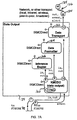
Turning now to FIGS. 2-21 of the drawing, depicted therein is a data routing system 120 of the present invention. The example data routing system 120 operates in the same basic manner as the data routing system 20 described above but is optimized to operate in a working environment defined by a motion control system.
FIG. 2 illustrates that the data routing system 120 is a collection of modules or components used to collect machine data from the data origins 122 and then send some or all of the data collected to the data destinations 124. The data destinations 124 may be either a local data destination (for later replication to a remote data destination) or a remote site (either a remote data routing system or third party data destination).
The example motion system 122 as defined in U.S. Pat. No. 5,691,897, but other motion systems may be used instead or in addition. As will be described in further detail below, the motion system 122 defines or is associated with one or more application programming interfaces. The motion system 122 is not per se part of the present invention and will not be described herein beyond what is necessary for a complete understanding of the present invention.
The data destinations 124 may use the data delivered by the data routing system 20 for a variety of purposes. A primary function of the data destinations 124 is to optimize and/or monitor the operation of the machines and/or devices forming the motion control system that the motion services 122 or other software used by the data sources 142 communicate with. The data destinations 124 can thus take any one or more of a number of forms, including a database system, a plant floor process management system, software used to optimize overall production flow, or other software systems, and/or another data routing system as described herein.
The example data routing system 120 is connected to the data destination 124 through a network 126. The network 126 is a combination of hardware and software architectures that forms a link between two or more computer systems. Examples of network architectures include a packet based network, a streaming based network, broadcast based network, or peer-to-peer based network. Examples of networks that may be used as the network 126 include a TCP/IP network, the Internet, an Intranet, a wireless network using WiFi, a wireless network using radio waves and/or other light based signals, and the like.
The software components making up the example data routing system 120 may be organized into three module groups: a data input module group 130, a data cache module group 132, and a data output module group 134. The data input module group 130, data cache module group 132, and data output module group 134 typically run on a processor forming part of a computer system, but may be configured to operate across several discrete processors forming part of one or more computer systems connected by a computer network.
The data input module group 130 comprises a data collection component 140 and a plurality of data source components 142 a and 142 b. The data cache module group 132 comprises a data store component 150 and one or more data cache components 152. The data output module group 134 comprises a data output component 160, one or more data transport components 162, a data formatter component 164, and an inference engine component 166.
The data collection component 140 is responsible for collecting data from the machine asset and routing all data collected to the data cache module group 132. The data collection component 140 is responsible for managing one or more data source components 142 for which data is collected and route the data collected to the data cache module group 132.
The data source components 142 a and 142 b communicate with the motion system 122. Each data source communicates with the motion system using whatever means are available including to the use of application programming interfaces (API) 170 a, 170 b, and 170 c associated with the motion system 122, using (API) provided by a motion system vendor, or using network or other communication protocols. The example data source component 142 a is configured to receive data from the API's 170 a and 170 b, while the example data source component 142 b is configured to receive data from the API 170 c.
The example data collection component 40 manages one or more data source components 142 and is responsible for routing the data collected to the data store component 150 of the data cache module 132. Optionally, each data collection component 140 may communicate directly to the motion system 122 without the need for an intermediary data source component 142. However, the use of the data source component 142 allows for code reuse as the data collection component 140 may then implement all common functionality, thus making each data source component 142 extremely thin and easy to build and maintain. In addition, the use of each data source components 142 allows the data collection component 150 itself to be independent of each data origin with which each data source component 142 communicates to collect data.
Each data source component 142 is responsible for mapping the data collected from the data source (i.e. XMC API, XMC CNC API, Protocol Server, or proprietary data source) into the format expected by the data collection component 140 and ultimately the data store component 150. The main goal of the data source components 142 is to provide a consistent interface to the data origin 122, thereby freeing the client from the details of the data origin 122 and allowing all data source components 142 to act and operate in the same manner from the perspective of the data collection component 140.
The data cache module group 132 caches the data received so that it may later be analyzed or otherwise processed. In particular, the data store component 150 manages one or more data caches 152 and is responsible for storing all data received and giving access to all data stored. Optionally, each data store component 150 could cache all data received directly without the need for an intermediary data cache 152. However, the use of the data cache or caches 152 allows for code reuse and also allows the data store component 150 to remain independent of any caching technologies used by each data cache component 152. The data store component 150 may then implement all common functionality, thus making each data cache module 132 also extremely thin and easy to build and maintain.
The terms “primary data cache” and “secondary data cache” may be used to refer to one or more of the data caches 152 depending upon whether certain features of the data cache module 132 are implemented and/or used as will be discussed in detail below. The suffix “a” is used in FIG. 2B to designate a primary data cache, and the suffix “b” is used to designate a secondary data cache.
Each data cache 152 stores data in a data target 172 such as a database on a hard drive, RAM memory, or another persistent or volatile storage medium. The term “data target” is used herein to refer to any device or machine or location on a device or machine that can produce data as defined herein. The main purpose of the data caches 152 is to provide a consistent interface to the data storage medium used so that the caches 152 appear to be the same to the user, thus freeing the client of any details handling various caching mechanisms.
The data output module group 134 is responsible for sending the data collected by the data input module group 30 and/or stored by the data cache module group 32 to the data destination 122. The data output component 160 manages the other components forming the data output module 34, namely, the data transport components 162, the data formatter component 164, and the inference engine component 166.
More specifically, the data output component 160 is responsible for sending data to one or more data destinations 124. As generally described above, the data destination may be an enterprise data management system, an artificial intelligence system, a plant floor process management system, software used to optimize overall production flow, another data routing system such as the systems 20 and 120 described herein, and/or other software systems used to optimize and/or monitor how the overall factory operates based on how each machine making up the factory runs.
The inference engine component 166 is responsible for mapping the data elements received from the data input module group 130 or data cache module group 132 through the data output component 160 to the data destinations 124 to which the data elements are to be sent. The data transport component 162 defines which data elements are to be sent to which data destination 124. When performing this mapping, the inference engine component 166 also optionally provides a set of rules and/or other criteria that are used to determine whether or not each output defined by the data transport component 162 should ‘fire’. For example, the inference engine component 166 may use one or more of the following logic systems: artificial intelligence systems, fuzzy logic algorithms, neural network pattern matching, genetic algorithms, expert system logic, and/or other computer based decision-making and/or pattern matching based systems, to determine when a given set of one or more data elements should be sent out. In the simplest case, an identity transform may be used which causes all data inputs received to be sent out as matching data outputs.
The data formatter component 164 is used to format all or portions of the data set to be transported to the data destinations 124. For example the data formatter component 164 may be used to format data output by the inference engine component 166 into a certain XML schema or other proprietary data format.
The data transport component 162 is responsible for sending the data to the ultimate data destination 124, including an enterprise database, an enterprise software system, or even another data routing system such as the data routing system 120.
Referring still to FIG. 2, also depicted therein is a data manager 180 that allows the user to manage operation of the data routing system 120. The data manager 180 controls access to property pages exposed or generated by user-interface components associated with the components 140, 150, 160, 162, 164, and 166. Property pages may also be exposed or generated by user interface components associated with the components 142 and 152. In particular, the example data routing system 120 comprises data collector property pages 182, data store property pages 184, data output property pages 190, data transport property pages 192, data formatter property pages 194, and inference engine property pages 196. As will be described in further detail below, the property pages 182, 184, 190, 192, 194, and 196 allow the user to initialize, configure, and control the components 140, 150, 160, 162, 164, and 166, respectively.
In the following discussion and in the drawings, the property pages 182, 184, 190, 192, 194, and 196 also refer to the user-interface components associated with these property pages. The property pages 182, 184, 190, 192, 194, and 196 and other interface elements are separated from the components 140, 150, 160, 162, 164, and 166 in the system 120 to optimize the overall system flexibility and facilitate evolution toward new and future user interface technologies such as HTML based web user interface, SOAP/XML based interfaces, Microsoft .NET based interfaces, etc. Optionally, however, the components 140, 150, 160, 162, 164, and 166 could directly expose property pages and other user-interface elements.
Referring now to FIGS. 3-8, the interactions of the components and property pages forming the data input module group 130, data cache module group 132, and data output module group 134 will now be described in further detail in the various scenarios required to implement the functions of the example data routing system 120.
Before using the data routing system 120, the system must first be initialized. During initialization, all components are started and configured with their initial settings. Initializing the system involves configuring the data routing system 120 so that it knows what data to collect, where to collect it from, how to process the data collected and where to send the processed data. Once initialized, the system is ready to begin collecting, storing and processing machine and/or device data.
The initialization process includes to levels. First, the overall data routing system 120 must be configured by connecting one or more data collection components 140 data and one or more data output components 160 to the data store component 150. Once connected, the components making up each of the data input module 130, data output module 134, and data cache module 132 groups must next be configured.
The process of initializing the data routing system 120 will now be described with reference to FIG. 3
Initially, the data manager 180 is run to configure the overall system 120.
The data manager 180 of the data routing system 120 next uses the data store property pages 184 paired with the data store component 150. The data store property pages 184 query the data store component 150 for all entries in the data output module group 134 category (or optionally queries for each entry directly using the OLE Component Categories) and displays each entry visually in the property page 184.
Next, after the user selects which data output module or systems 134 to activate, the list of active data output components 160 associated with the selected data output module or systems 134 is sent back to the data store component 150 so that it may use the active components. The data store component 150 could optionally query a separate ‘configuration’ component used to select the active data output modules 134 to use later when processing data to be output. Additionally, the activation of each active component 160 may optionally be activated programmatically instead of by the user.
During its initialization, the data store component 150 creates an instance of each activated data output component 160 so that the data store component 150 can send data update events to each upon receiving new cache data.
Similar to the configuration of the data output module group 134, the data store property pages 184 query the data input module group 130 for a list of supported data collection components 140. Optionally, the data store component 150 may query the data collection components 140 of the data input module group 130 and display each these data collection components 140 visually so that the user can activate all components 140 that are appropriate for collecting data.
Once selected visually by the user, the active list of one or more data collection components 140 is sent to the data store component 150. Optionally, the data store component 150 could query a separate ‘configuration’ component used to select the active data output modules 134 to use later when processing data to be output. Additionally, the activation of each component may optionally be activated programmatically instead of by the user.
During initialization, the data store component 150 creates an instance of each active data collection component 140.
Once the main components data store component 150, data collection component 140, and data output component 160 of the data output module 134 are configured, the user (or configuration program) must configure the components used by each of the systems 140, 150, and 160. The main configuration task for the data collection component 140 is that of selecting the data source components 142 (and the data items supplied by each) from which data is to be collected. The process of configuring the components used by the systems 140, 150, and 160 will now be described with reference to FIG. 4.
The following steps take place when configuring the data collection component 140 and related components.
First, the data manager 180 is used to configure the data collection component 140.
Second, the data collector property pages 182 are used to configure the data collection component 140. Optionally, all configuration may be done programmatically by another software module.
Each of the data collector property pages 182 queries the Data Source OLE Category of components to see what data source components 142 are available. Optionally, the data collection component 140 may be queried for the list of all data source components 142 available.
A visual list of available data source components 142 is next constructed, thus allowing the user to select which data source component or components 142 to use when collecting data. Optionally, the data collection component 140 could directly talk to the data source components 142; however such direct communication would reduce code reuse as the data collection component 140 allows each data source component 142 to be very thin, making these components 142 easy to build and maintain.
Finally, after the user selects the data source components 142 to use, a list of active data source components 142 is passed to the data collection component 140, which then creates an instance of each selected component.
Optionally, each data source component 142 may use an associated property page (not shown) that allows the user to visually (or software to programmatically) configure and select the data inputs from which data is to be collected by each data source component 142. Each data collector component 140 may also define a set of data inputs that the user may configure and select; however this it not optimal as the data source components 142 allow each data collector component 140 to remain independent of how each data origin actually works; i.e. the data items they provide and how the data for each data item is actually collected.
Referring now to FIG. 5, the following steps take place when configuring the data cache module group 132, which includes the data store component 150 thereof. Configuring the data store component 150 requires the selecting of the data cache 152 to use. When caching data there are three main methods that may be employed: (1) cache all data to memory only; (2) cache all data to a persistent storage such as a database, or (3) a mixture where data is initially cached to memory and then ‘rolled-over’ into the persistent store at certain intervals or after a specified amount of data has been collected. All three models are utilized by the data cache module group 132 of the data routing system 120, where only one method is necessary to build a picture of the overall state of the data origin at a given moment in time.
In a first step shown in FIG. 5, the data manager 180 of the data routing system 120 is used to configure the data store component 150 and associated components using the embedded data store property page 184. As described above, the data store component 150 can be configured to implement all user aspects that it needed to edit and otherwise allow the user interact with the data and configuration managed by the component. However, separating the user interface from the component in a parallel component has several advantages that allow for easily adopting future user-interface based technologies such as HTML, Windows .NET, and thin client. For these reasons the user interface has optionally been separated from the main logic making up the data store component 150. As generally described above, this same design organization is used throughout the entire system 120 by all components having an associated property page.
The data store property page 184 component queries the data store component 150 for the list of data cache components 152 that are available and displays the list visually. The list of available components 152 may optionally be provided programmatically by a separate component used for configuration. As an additional option, the data store property page 184 may directly query the Cache Category of components in the OLE Component Category.
From the data store property page 184, the user visually selects the specific data cache components 152 to use and the specific caching strategy to employ (single caching or roll-over where data from one cache is rolled over to another cache based on certain criteria such as an interval of time, or a data cache data threshold being met). The selected data cache components 152 and strategy selected by the user are transferred to the data store component 150 which then stores the settings.
Each data output component 160 and associated components act as a data output ‘pipeline’ where data follows a set of steps that determines what data will be output, what format that data will be output in, and where the data will be sent. Referring now to FIG. 6 of the drawing, depicted therein are the steps that take place when configuring the data output component 160 and its related components.
First, the data manager 180 is used to configure the various aspects of the data output component 160 and its associated components.
When configuring the data output component 160, the data output property page 190 parallel component acquires the list of inference engine components 166, data formatter components 164, and data transport components 162 that are available. Once the list of data transport, data formatter, and inference engine components 162, 164, and 166 is acquired, a visual display of the list is created on the data output property page 190 so that the user can select one or more of the components 162, 164, and 166 from the list as appropriate for their application.
To obtain this list of components, the data output property page 190 may either query the data output component 160 or directly query the OLE Category for each of the data transport component 162, data formatter component 164, and inference engine component 166. If the data output component 160 is queried for the list of available components in each category, the data output component 160 in turn may then internally query a pre-configured list or the OLE components falling into each respective OLE Category for the data transport component 162, data formatter component 164, and inference engine component 166.
After the user selects one or more data transport components 162, one or more data formatter components 164, and one or more inference engine components 166, the list of components to activate is sent to the data output component 160, which stores the component information as its active components and then creates an instance of each component.
Next, each data transport component 162 is queried for its list of supported outputs. The list of supported data outputs is then passed to the inference engine component or components 166 selected.
Next, the data output component 160 queries the data store component 150 for its list of supported data items, usually stored in the data cache components 152 and previously selected when configuring the data collection component 140. The list of supported input data items is then passed to the inference engine component or components 166 selected.
When the inference engine component or components 166 have both the inputs and outputs available, the user may optionally configure rules or other criteria used to determine when each output is ‘fired’ based on the input data received. As examples, one or more of a set of Fuzzy Logic rules, a previously trained Neural Network pattern, a Genetic Algorithm fitness, Expert System logic, or other custom logic may be used to determine when certain outputs are sent through the data output pipeline to the data destination.
In addition, the data formatter component or components 164 may also be configured to output data in data formats supported by each data destination 124. For example, a data formatter component 164 may be used to output data items received in a certain proprietary schema. However, the data formatter component 164 would need to be configured so that it would know how to match the data items received to the proprietary schema. This step in the configuration process would allow the user, or another software program, to make this configuration.
And finally, the data transport component or components 162 would need to be configured so that they could properly send data received to the end data targets that it supported. For example, a data transport component 162 configured to use TCP/IP may need to have target TCP/IP addresses configured or TCP/IP ports configured telling the component 42 where to send the data.
Once initialized, the data routing system 120 is ready to start collecting data and storing all data collected as previously configured. FIGS. 7A and 7B depict the interactions that take place when collecting data.
First each data source component 142 either polls for data or receives previously configured events from its data origination. For example, when using the motion system 124 or an Protocol Server as the data origin, events may be received telling the data source component 142 that new data is available.
Upon receiving a data update event, the data source component 142 fires an event to its respective parent data collection component 140.
Upon receiving its event, the data collection component 140 then fires an event to the data store component 150.
Upon receiving each data update event, the data store component 150 uses the active caching component or components 152 to store the data. Optionally, the data cache module 132 may employ a roll-over strategy in which data received is passed to one or more data cache modules 132 after a certain criteria is met such as in interval of time passing or a data caching threshold being met.
After caching the data, the data store component 150 fires a data update event to any data output component or components 160 connected to the data store system 132.
Upon receiving the data update event, the data output component 160 may optionally query the data store component 150 for more data if needed to gain a full description of the current state of the machines forming the motion system 122.
All data input information is then passed to the inference engine component 166 for processing. Upon receiving the data, the inference engine component 166 runs its preconfigured rule set against the data set received and produces the output (if any) that is eligible to be sent to the data destinations 124. If the inference engine component 166 employs a dynamic model of the data, its internal model may alter itself based on the input data received. For example, an inference engine component 166 that uses a neural network may ‘learn’ from the data by changing the neural network's weights based on the data input values received.
If data is eligible to be output, and a data formatter component 164 is used, the output data received from the inference engine component 166 is then sent to the data formatter component 164. Upon receiving the data, the data formatter component 164 transforms the data received into the supported output data format and passes the new output data back to the data output component 160.
The formatted data is then passed to the data transport component or components 162 to be transported or sent to the data destinations 124. If a data formatter component 164 is not used, the raw data format output from the inference engine component 166 is used and passed directly to any active data transport component 162. Upon receiving the output data, the active data transport component or components 162 send the data to their respective data destinations 124. For example, a TCP/IP transport would packetize the data into TCP/IP packets and send the data stream to a preconfigured TCP/IP address/port. Alternatively, a wireless transport may broadcast the data out on a pre-configured frequency.
Referring now to FIG. 8 of the drawing, depicted therein is a relationship among the interface windows and dialogs that form the property pages used to configure the example data routing system 120. The data manager 180 presents to the user a main window 220 (FIG. 9) that is used to access the data property pages 182, 184, 190, 192, 194, and 196 used to configure all settings of the data collection component 140, data store component 150, and data output component 160 forming up the system 120.
The example main window 220 presented by the data manager 180 to configure each of the main components 140, 150, and 160 is shown in FIG. 9. In particular, the main page 220 of the data manager 180 acts as a control panel that allows the user to configure and monitor how data flows from each data source 122 to the eventual data destination 124.
Each of the user interface elements of the main page 220 on the data manager 180 will now be described with reference to FIG. 7.
A “Configure” button 222 allows the user to configure the overall system 120 by building up the overall data transfer pipeline. This option is only available when running the application as an Administrator on the system.
A “Start” button 224 starts monitoring the data source components 142 and feeds the data received through the system 220.
A “Stop” button 226 stops monitoring the data source components 142 and shuts down the entire monitoring process.
A “Monitoring” icon 230 visually displays whether or not monitoring is currently enabled.
A “Close” button 232 closes the monitoring application window but does not close the application. Since the application runs as a system tray application, you must exit the application by right clicking on the system tray icon.
A “Status” window 234 visually shows the overall configuration and status of the system including all nodes making up the data input module 130, data store system 132, and data output module 134.
The following sections describe how to build and configure the overall system 120 using examples of the various property pages 182, 184, 190, 192, 194, and 196.
Referring initially to FIG. 10, depicted therein is a configuration dialog window 240 that is associated with the data manager 180. The configuration dialog window allows a user to build the overall data routing system 120. The user interface elements making up the configuration dialog window 240 are as follows.
An “Add Data Collector . . . ” button 24 displays a dialog containing a list of all data collection components 140 available to the system. Once selected, the selected data collection components 140 are added to the system 120. The data collection components 140 are connected to the data store component 150 so that data events are sent to the data store component 150 each time data items are received by each of the data collection components 140 from their respective various data source components 142.
An “Add Data Output . . . ” button 244 displays a dialog containing a list of all data output modules 134 available to the system. Once selected, the data output modules 134 are added to the system. Each data output module 134 manages a data pipeline that may involve inference rules or other decision-making technology that tell when to fire each data output.
A “Delete” button 246 removes a module from the list of components making up the overall data routing system 120.
A “Load” button 250 loads the components of a previously saved data routing system 120 from a persistent storage medium such as a file or database.
A “Save” button 252 saves the current data routing system 120 to a persistent storage medium such as a file or database.
A “Close” button 254 closes the configuration dialog.
A “Node” control 260 contains the current modules making up the data routing system 120, including data collection components 140, data store components 150, and data output components 160.
An “About” property page 262 displays information about the currently selected module in the node list.
A “Settings” property page 264 displays a property page corresponding to the currently selected node in the node list. The property page allows the user to configure the settings specific to the node selected.
Examples of interface elements that may be used to implement the property pages 182, 184, 190, 192, 194, and 196, as well as other related property pages, will now be described with reference to FIGS. 11-18. The “Delete”, “Load”, “Save”, and “Close” interface elements depicted in FIGS. 11-18 apply to the “Node” Control on the left part of each figure (not shown) and will not be described in detail below.
An example of the data collector property page 182 is depicted in FIG. 11 of the drawing. The data collector property page 182 allows a user to configure the components, such as the data collection components 140 and/or data source components 142, of the data input module group 130.
A “Data Sources” list box 270 contains a list of all data source components 142 available to the system. The list of available data source components 142 is acquired by either directly enumerating the Data Source OLE Category of components or by querying the data collection component 140 for all data source components 142 that it ‘knows’ about.
A “Select” button 272 adds the currently selected item in the list of data source components 142 to the currently selected data output module 134 in the main node list.
A “Target Scan Rate” edit field 274 allows the user to input a global scan rate that applies to all data source components 142 that may be controlled using a global scan rate.
A data source property page 280 is depicted in FIG. 12. The data source property page 280 allows the user to select the data items made available by each data source component 142. The selected data items are then fed into the data store component 150 and eventually on into the selected inference engine component 166. The following user-interface elements make up the data source property page 280.
A “Data Items” list box 282 contains a list of all data items made available by each data source component 142. The user must enable the data items that they want to monitor in their system. The list of available data items is acquired by browsing a particular data source component 142.
A “Scan Rate” edit box 284 allows the user to enter the scan rate to use for this specific data source (which may be different from the global scan rate). If no scan rate is entered, the default global scan rate is used when appropriate.
A data store property page 290 depicted in FIG. 13 is used to configure the data store component 150 by selecting and configuring the data cache or caches 152 used and the specific caching strategies for each. The following user-interface elements make up the data store property page 290.
A “Data Caches” list box 292 contains a list of all data caches 152 available to the system 120. The list of available data caches 152 may be acquired either by directly enumerating the data cache OLE Category of components or by querying the data store component 150 for a list of active data caches 152.
A “Select” button 294 adds the currently selected item in the “Data Caches” list box 290 to the currently selected data store component 150 in the master node list.
Referring now to FIG. 14, depicted therein is a data cache property page 320 that allows the user to configure the specific caching strategy to be used by each data cache 152. The following user interface elements make up the data cache property page 320.
An “Enable data roll-over” check-box 322 allows the user to enable/disable data roll-over. When enabled, data placed in a particular data cache 152 can roll-over into another, or secondary, data cache 152 upon meeting certain criteria specified by other of the user-interface elements forming the data cache property page 320.
An “After reaching cache data threshold of” radio button 224, if selected, determines that roll-over occurs when a certain number of bytes are cached in the primary data cache, assuming that data cache roll-over is also enabled by check box 322. A caching threshold data field 324 a allows the user to specify the data cache threshold. After reaching the roll-over threshold level, all data currently in the primary data cache 152 a is copied to the secondary data cache 152 b.
An “After time interval of” radio button 326, when selected determines that roll-over occurs at specifically set time intervals, again assuming that data cache roll-over is enabled by check box 322. A time interval data field 326 a allows the user to specify the duration of the time interval. Upon the expiration of each time interval all data in the primary data cache 152 a is automatically copied over to the secondary data cache 152 b and then removed from the primary cache 152 a.
A “Roll-over to” list-box 328 contains a list of data caches that can be used as secondary caches 152 b. The primary cache 152 a rolls data over to the secondary cache 152 b selected by pressing a “Select” button 328 a.
Referring now to FIG. 15, the data output property page 190 is depicted therein in further detail. The data output property page 190 is used to configure the data output module 134 by selecting the data transport components 162, data formatter component 164, and inference engine component 166 that are to make up the data output pipeline. The following user-interface elements make up the data output property page 190.
An “Interface Engines” list-box 330 contains a list of all inference engine component or components 166 that are available to the system 120. A first “Select” button 330 a allows one or more of the inference engine components 166 to be selected. As generally described above, each inference engine component 166 is responsible for mapping input values to output values and determining when each data element should actually be sent to the data destination 124.
A “Data Formatters” list-box 332 contains a list of all data formatter components 164 that are available to the system 120. A second “Select” button 332 a allows one or more of the data formatter components 164 to be selected. Each data formatter component 164 is responsible for transforming data input into another data format that is output as output data.
A “Data Transports” list-box 334 contains a list of all data transport components 162 that are available to the system 120. A third “Select” button 334 a allows one or more of the data transport components 162 to be selected. Each data transport component 162 is responsible for sending the data received to the ultimate data destination 124, such as an enterprise database, analysis system, another data routing system, or the like.
The inference engine property page 196 will now be described in further detail with reference to FIG. 16. The inference engine property page 196 is used to configure the settings defining how the inference engine component 166 actually works. The inference engine component 166 maps inputs received to expected outputs defined by the data transport component 162. When mapping inputs to outputs, the inference engine component 166 optionally uses decision logic to determine whether or not each output should fire (i.e. be sent on to one or more data transport component 162) based on the inputs received. The user interface elements making up the inference engine property page 196 are as follows.
An “Input Data Items” list-box 340 contains a list of all data inputs received from the data input module 130 via the data store component 150. An “Output Data Items” list-box 342 contains a list of all data outputs received from the data output module 134 via the data transport component 162. A “Rule Map” list-box 344 contains a list of rules that define how to map the received data inputs to the outputs.
In this sample inference engine component 166, the user drags items from the Input Data Items list box 340 into the inputs making up the rule-map as listed in the Rule Map list box 344. The rule-map associated with each of the items in the Input Data Items list box 344 defines when to fire output to each defined output.
An example data formatter property page 194 is depicted in FIG. 17. The data formatter property page 194 allows the user to configure how the final data output is actually formatted. For example, the example property page 194 depicted in FIG. 17 illustrate how to map data outputs into an XML schema. The following user interface elements make up the data formatter property page 194.
An “XML Schema Map” 350 control contains an editable XML Schema that allows a user to drag an output data item into different portions of the schema essentially ‘linking’ the data item to that portion of the XML schema. When linked, the final XML data file is built by using the XML schema and then placing data from each output data item into the slots where they are linked into the XML schema.
An “Output Data Items List” list-box 352 contains a list of all data outputs available as defined by the data output module 134 via the data transport component or components 162.
Depicted in FIG. 18 is an example of a data transport property page 192. The data transport property page 192 allows the user to configure the specific settings of each data transport component 162 used to communicate with the data destination or destinations 124. The example property page 192 depicted in FIG. 18 is an example property page for a data transport component 162 that communicates across a TCP/IP based (wire-based or wireless) network. The data transport property page employs the following user interface elements.
A “Target TCP/IP Address” 360 edit field allows the user to enter the target TCP/IP address of the machine or machines forming destinations where data is to be sent.
A “Target TCP/IP Port” edit field 362 allows the user to specify a set of one or more TCP/IP ports to use on the target TCP/IP address.
A “Use UDB Broadcasting” radio button 364 directs the transport to broadcast the output data using the UDP broadcasting protocol and ignore the target TCP/IP address as data will be sent to all machines forming data destinations 124 on the network 126.
A “Use Peer-to-Peer Messaging” radio button 366 directs the transport to use a peer-to-peer messaging protocol such as the one used with Windows Instant Messenger, where data is sent immediately to the target machine forming the data destination 124 and may optionally be displayed in an Instant Messenger viewing application such as Windows Messenger.
A “Use Data Streaming” radio button 368 directs the transport to use a data streaming technology where the data outputs are streamed to the target(s) in a manner similar to that of a streaming music or video source. Optionally, the data outputs may also be interleaved into an existing music, video, or other data streaming data source.
A “Use Virtual Private Networking Tunneling” radio button 370 directs the transport to use a tunneling technology, where the data packets making up the output data are embedded within another packet type, optionally encrypted and secured, and then sent to the target over another protocol such as HTTP, or in this case the PPTP or L2TP protocol. SOAP or XML messaging is another manner of tunneling where the data is placed within a SOAP or XML ‘envelope’ and then sent over to the output target using the SOAP or other XML messaging protocol.
A “Use SMTP E-Mail Format” radio button 372 directs the transport to package the output data sets into an e-mail format and sends it to the target. Further configuration may be required to actually setup a specific e-mail address for the recipient.
A “Use SNMP Format” radio button 374 directs the transport to use the SNMP transport to communicate with the output target.
An “Enable Data Encryption” check-box 380 enables data encryption such that the data is encrypted before transmission. A “Use Kerberos Security” check-box 382 enables Kerberos security. A “Use 128 bit Encryption” check-box 384 enables 128-bit encryption for the output data packets.
An “Enable Transmission Timeout” check-box 386 enables transmission time-out on each communication with the target. When enabled, the sender only waits for an amount of time specified in a data field 386 a for a response from the data destination 124, after which response data received from the target is ignored.
The example data routing system 120 is a modular system made up of a set of components as generally described above. In this case, each component is based on a component technology, such as OLE/COM technology defined by Microsoft Corporation.
Optionally, each component uses a separate ‘parallel’ ActiveX component to implement all user interface aspects of the main component, also as generally described above. Each ActiveX component may be implemented either within the main component module or separately in its own module. Bundling each object within one module is not required as they may be located at any location (i.e. across a network, and so forth), but doing so may optimize all communication between modules. How and where components are implemented is more of a logistical decision because, once components are built and deployed to the field, it is difficult to update a single component if all components are implemented within a single DLL or EXE module.
FIG. 19 illustrates that the components forming the data routing system conform to a single interface identified as the IXMCDirect interface. OLE Categories are used to determine how many components fall into a certain group of components. Components used by the example data routing system 120 fall into the following categories:
    • Data Input Components—Typically, this category includes a single data collector component, but multiple data input components may be used in a large distributed environment.
    • Data Source Components—Many data source components are often used at the same time.
    • Data Output Components—Many data output components are often used at the same time, with each data output component defining at least part of a data output pipeline.
    • Inference Components—One or more inference engine components are used by each data output component.
    • Data Formatter Components—One or more data formatter component components are typically used by each data output module.
    • Data Transport Components—One or more data transport components are typically used by each data output module.
The IXMCDirect interface depicted in FIG. 19 is used for most communications between components of the data routing system 120. The IXMCDirect interface is made up of the following functions, which are specified in standard OLE/COM IDL format.
    • A GetProperty method is used to query a specific property from the component implementing the interface.
    • A SetProperty method is used to set a specific property from the component implementing the interface.
    • An InvokeMethod method is used to invoke a specific action on the component implementing the interface. An action can cause an event to occur, carry out a certain operation, query a value, and/or set a value within the component implementing the method.
More detailed descriptions of each of the methods implemented by objects implementing the example IXMCDirect interface are described below.
The IXMCDirect:GetProperty method is used to query the property corresponding to the property name ‘pszPropName’. Each component defines the properties that it supports. The following table summarizes the GetProperty method implemented by the example IXMCDirect interface:
Syntax HRESULT GetProperty( LPCTSTR pszPropName,
LPXMC_PARAM_DATA rgData,
DWORD dwCount );
Parameters LPCTSTR pszPropName - string name of the
property to query.
LPXMC_PARAM_DATA rgData - array of
XMC_PARAM_DATA types that specify each
parameter corresponding to the property. For example,
a certain property may be made up of a number of
elements - in this case an array of XMC_PARAM_DATA
items is returned, one for each element making up
the property. In most cases a property is made up of
a single element, thus a single element array is
passed to this method. For more information on the
XMC_PARAM_DATA type, see below.
DWORD dwCount - number of XMC_PARAM_DATA
elements in the rgData array.
Return HRESULT - NOERROR on success, or error code
Value on failure.
The IXMCDirect:SetProperty method is used to set a property in the component corresponding to the ‘pszPropName’ property. For the set of properties supported by the component, see the specific component description. The following table summarizes the SetProperty method implemented by the example IXMCDirect interface:
Syntax HRESULT SetProperty( LPCTSTR pszPropName,
LPXMC_PARAM_DATA rgData,
DWORD dwCount );
Parameters LPCTSTR pszPropName - string name of the property
to set.
LPXMC_PARAM_DATA rgData - array of
XMC_PARAM_DATA types that specify each para-
meter corresponding to the property. For
example, a certain property may be made up of
a number of elements - in this case an array
of XMC_PARAM_DATA items is returned, one for
each element making up the property. In most
cases a property is made up of a single element,
thus a single element array is passed to this
method. For more information on the
XMC_PARAM_DATA type, see below.
DWORD dwCount - number of XMC_PARAM_DATA
elements in the rgData array.
Return HRESULT - NOERROR on success, or error code
Value on failure.
The IXMCDirect:InvokeMethod method is used to call a specific method implemented by the component. For more information on the methods supported, see the description of the specific component. The following table summarizes the InvokeMethod method implemented by the example IXMCDirect interface:
Syntax HRESULT InvokeMethod( DWORD dwMethodIdx,
LPXMC_PARAM_DATA rgData,
DWORD dwCount );
Parameters DWORD dwMethodIdx - number corresponding to the
specific method to invoke. For more information on
the method indexes available, see the set of
namespaces defined for the component.
LPXMC_PARAM_DATA rgData [optional] - array of
XMC_PARAM_DATA types that specify each
parameter for the method called.
For more information on the
XMC_PARAM_DATA type, see below.
NOTE:
if no parameters exist for the method called,
a value of NULL must be passed in.
DWORD dwCount [optional] - number of
XMC_PARAM_DATA elements in the rgData array.
NOTE:
if no parameters exist for the method called,
a value of 0 (zero) must be passed in for
this parameter.
LPXMC_PARAM_DATA rgData [optional] -
namespace associated with the instance of
the custom extension module added.
Return HRESULT - NOERROR on success, or error code
Value on failure.
This methods supported by each component making up the system 120 will now be described. Initially, the general methods supported by the majority of the components forming the system 120 will be first be described; the methods supported by each individual component will then be discussed.
The XMC_DE BROWSE_GET_COUNT general method returns the number of data items in the browse set supported by the component and is described in the following table.
Index 8020
Data In None
Data Out rgData[0] - (number) DWORD, number of browse elements.
The XMC_DE_BROWSE_GET_ITEMS general method returns the number of data items in the browse set supported by the component and is described in the following table:
Index 8021
Data In rgData[0] - (number) DWORD, maximum number of
elements to collect.
Data Out rgData[0] - (number) number of elements collected,
total number of elements will equal (rgData[0] * 2 + 1).
rgData[1] - (string) name of the first browse element.
rgData[2] - (number) adt of the first browse element.
rgData[1 + n*2] - (string) name of the n'th
browse element.
rgData[2 + n*2] - (number) adt of the n'th
browse element.
The XMC_DE_SYSTEM_CONNECT_CMPNT general method is used to connect one server to another so that they may interact with one another and is described in the following table:
Index 8000
Data In rgData[0] - (number) DWORD, type of component. The type
of component is a value that is server specific. For
component type information, see the description for this
method under each server's description.
rgData[1] - (string) LPTSTR, component class id as an ASCII
string.
Data Out None.
The XMC_DE_SYSTEM_DISCONNECT_CMPNT general method is used to disconnect one server from another so that they stop interacting with one another and is described in the following table:
Index 8001
Data In rgData[0] - (number) DWORD, type of component. The type
of component is a value that is server specific. For
component type information, see the description for this
method under each server's description.
rgData[1] - (string) LPTSTR, component class id as an ASCII
string.
Data Out None.
The XMC_DE_DATA_PROCESS general method is called by a client to process data where a data set is input, processed in some way by the server, and then the resulting data is returned as output. The XMC_DE_DATA_PROCESS method is described in the following table:
Index 8063
Data In rgData[0] - (number) DWORD, number of data items input.
rgData[1 + n*2] - (string) LPCTSTR, name of the data item
input.
rgData[2 + n*2] - (number or string), value of the data item.
Data Out rgData[0] - (number) DWORD, number of data items output.
rgData[1 + n*2] - (string) LPCTSTR, name of the data item
output.
rgData[2 + n*2] - (number) value of the data item.
The XMC_DE_DATA_PROCESS CONFIGURE general method is used to configure what type of data is returned when processing a given data item. For example in the server may be configured to return the minimal amount of data on each read (i.e. just the data item value), or the server may be requested to return more substantial data. The XMC_DE_DATA_PROCESS_CONFIGURE method is described in the following table:
Index 8062
Data In rgData[0] - (number) DWORD, flag describing the
type of data to be returned when processing data.
The following flags are supported:
XMC_DE_READ_DATA_FLAG_TIMESTAMP -
requests that the time stamp recorded
when processing the data is returned.
NOTE:
by default, the data item value is always returned.
Data Out None.
The XMC_DE_DATA_READ general method is called by a client application to poll for data from the server and is defined in the following table:
Index 8061
Data In rgData[0] - (string) LPCTSTR, name of the data item to read.
Data Out rgData[0] - (number or string), data item value.
rgData[1] - (OPTIONAL number) DWORD, data item time-
stamp as a system time value.
NOTE:
Since the last items are optional, only those items
specified when configuring the data to receive are actually
sent.
The XMC_DE_DATA_READ_CONFIGURE general method is used to configure what type of data is returned when reading a given data item. For example, the server may be configured to return the minimal amount of data on each read (i.e. just the data item value) or the server may be requested to return more substantial data. The following table defines the XMC_DE DATA_READ_CONFIGURE method:
Index 8060
Data In rgData[0] - (number) DWORD, flag describing the
type of data to be returned on each read.
The following flags are supported:
XMC_DE_READ_DATA_FLAG_TIMESTAMP -
requests that the time stamp recorded
when reading the data is returned.
NOTE:
by default, the data item value is always returned.
Data Out None.
The XMC_DE_DATA_WRITE general method is used to write data to a server and is described in the following table:
Index 8064
Data In rgData[0] - (number) DWORD, number of data items.
rgData[1 + n*2]- (string) LPCTSTR, name of the data item.
rgData[2 + n*2] - (number or string), value of the data item.
Data Out None.
The XMC_DE_EVENT_ENABLE general method enables/disables a previously subscribed data item in the subscription list maintained by the server. Only enabled subscriptions actually fire. The XMC_DE_EVENT_ENABLE method is defined in the following table:
Index 2892
Data In rgData[0] - (number) DWORD, cookie (unique identifier)
associated with the subscription. This value is returned to
the client when calling the subscription XMCAPI above.
NOTE:
using a cookie value of zero (0) will enable/disable
ALL items subscribed to the server.
rgData[1] - (number) BOOL, TRUE to enable the
subscription(s), FALSE to disable the subscription(s). Only
enabled subscriptions actually fire events.
Data Out None.
This XMC_DE_EVENT_RECEIVE_DATA general method is called by the server (and implemented by the client) when each subscribed event fires and is described in the following table:
Index 8045
Data In rgData[0] - (number) DWORD, subscription cookie
corresponding to the subscribed data item.
rgData[1] - (number or string), data item value.
rgData[2] - (OPTIONAL number) DWORD, data item time-
stamp as a system time value.
rgData[3] - (OPTIONAL string) LPSTR, data item ASCII text
name.
rgData[4] - (OPTIONAL number) DWORD, data item unique
cookie.
NOTE:
Since the last three items are optional, only those
items specified when configuring the data to receive are
actually sent. If, for example, one or more data items are
NOT requested, then the items are returned in slots shifted
up toward rgData[1]. For example if only the data item name
is requested in addition to the default data items, the data
returned would look like the following:
rgData[0] - (number) DWORD, subscription cookie.
rgData[1] - (number or string), data item value.
rgData[2] - (string) LPSTR, data item name.
Data Out None.
The XMC_DE_EVENT_RECEIVE DATA_CONFIGURE general method is used to configure what type of data is returned on each event that is fired. For example in the server may be configured to send the minimal amount of data on each event (i.e. subscription cookie and data item value), or the server may be requested to return more substantial data. The XMC_DE_EVENT_RECEIVE_DATA_CONFIGURE method is defined in the following table:
Index 8044
Data In rgData[0] - (number) DWORD, flag describing the type
of data to be returned on each event. The following
flags are supported:
XMC_DE_EVENT_DATA_FLAG_TIMESTAMP -
requests that the time stamp recorded
when reading the data is returned.
XMC_DE_EVENT_DATA_FLAG_NAME - requests that
the data items ASCII text name be returned.
XMC_DE_EVENT_DATA_FLAG_DATA_COOKIE -
requests that the unique data item cookie
corresponding to the read made for the
data item be returned.
NOTE:
by default, the subscription cookie and data item
value are always returned.
Data Out None.
The XMC_DE_EVENT_SUBSCRIBE general method subscribes to a given data item activating the event interface when the subscription criteria are met for the data item. All subscribing components use the IXMCDirect interface to receive events received from the server for which they are subscribed. The XMC_DE_EVENT_SUBSCRIBE method is described in the following table:
Index 2890
Data rgData[0] - (number) DWORD, flags describing the
In initial state of the subscription. The following
flags are supported:
XMC_DE_EVENT_FLAG_ENABLED - subscription is
immediately enabled upon subscription.
XMC_DE_EVENT_FLAG_DISABLED - subscription is
disabled upon making the subscription. The Enable
function must be called to enable the subscription.
rgData[1] - (number) DWORD, number of subscription
criteria rules.
rgData[2 + (2*n)] - (number) DWORD, event condition
type where the following types are supported:
XMC_CNC_EVENTCONDITION_DATA_CHANGE - any
data changes in the data type above will trigger
the event.
XMC_CNC_EVENTCONDITION_DATA_EQUAL
XMC_CNC_EVENTCONDITION_DATA_LESSTHAN
XMC_CNC_EVENTCONDITION_DATA_GREATERTHAN
XMC_CNC_EVENTCONDITION_DATA_AND
XMC_CNC_EVENTCONDITION_DATA_OR
Each of the conditions above are used in a combined
manner. Where the logical condition (=, <, >)
are applied for each type respectively.
For example, in an array that contains the
following items:
rgData[2] = 4 (4 condition values)
rgData[3] = XMC_CNC_EVENTCONDITION_EQUAL
rgData[4] = 3.0
rgData[5] = XMC_CNC_EVENTCONDITION_LESSTHAN
rgData[6] = 3.0
rgData[7] = XMC_CNC_EVENTCONDITION_OR
rgData[8] = 1.0
rgData[9] =
XMC_CNC_EVENTCONDITION_GREATHERTHAN
rgData[10] = 5.0
the array would be evaluated using the following logic:
If (DATA <= 3.0 OR DATA > 5.0) then Trigger Event
rgData[3 + (2*n)] - (number) double, the value for the
condition. See above.
Data rgData[0] - (number) DWORD, cookie (unique identifier)
Out representing the subscription.
The XMC_DE_EVENT_UNSUBSCRIBE general method removes a previously subscribed data item from the subscription list maintained by the server and is defined in the following table:
Index 2891
Data In rgData[0] - (number) DWORD, cookie (unique identifier)
associated with the subscription. This value is returned to
the client when calling the subscription XMCAPI above.
NOTE:
using a cookie value of zero (0) will unsubscribe ALL
items subscribed to the server.
Data Out None.
The XMC_DE_SYSTEM_INITIALIZEHW general method is used to initialize any hardware systems associated with the component and is defined in the following table:
Index 500
Data In None.
Data Out None.
The XMC_DE_SYSTEM_SHUTDOWNHW general method is used to shutdown any hardware systems associated with the component and is defined by the following table:
Index 501
Data In None.
Data Out None.
The following discussion will define which of the general methods implemented are implemented by particular components of the system 120.
The data collection component 140 implements the general methods described above as indicated in the following table:
Not
Method Implemented Implemented
XMC_DE_BROWSE_GET_COUNT x
XMC_DE_BROWSE_GET_ITEMS x
XMC_DE_DATA_PROCESS x
XMC_DE_DATA_PROCESS_CONFIGURE x
XMC_DE_DATA_READ x
XMC_DE_DATA_READ_CONFIGURE x
XMC_DE_DATA_WRITE x
XMC_DE_EVENT_ENABLE x
XMC_DE_EVENT_RECEIVE_DATA x
XMC_DE_EVENT_RECEIVE_DATA_CONFIGURE x
XMC_DE_EVENT_SUBSCRIBE x
XMC_DE_EVENT_UNSUBSCRIBE x
XMC_DE_SYSTEM_CONNECT_CMPNT x
XMC_DE_SYSTEM_DISCONNECT_CMPNT x
XMC_DE_SYSTEM_INITIALIZEHW x
XMC_DE_SYSTEM_SHUTDOWNHW x
The following special notes apply to some of the general methods implemented by the data collection component 140.
The following component types are valid for the XMC_DE_SYSTEM_CONNECT_CMPNT method as implemented by the data collection component 140: the XMC_DE_CMPNT_TYPE_XMCDSRC, which specifies a data source component 142.
The following component types are valid for the XMC_DE_SYSTEM_DISCONNECT_CMPNT method as implemented by the data collection component 140: XMC_DE_CMPNT_TYPE_XMCDSRC, which specifies an data source component 142.
The data source component 142 implements the general methods described above as indicated in the following table:
Not
Method Implemented Implemented
XMC_DE_BROWSE_GET_COUNT x
XMC_DE_BROWSE_GET_ITEMS x
XMC_DE_DATA_PROCESS x
XMC_DE_DATA_PROCESS_CONFIGURE x
XMC_DE_DATA_READ x
XMC_DE_DATA_READ_CONFIGURE x
XMC_DE_DATA_WRITE x
XMC_DE_EVENT_ENABLE x
XMC_DE_EVENT_RECEIVE_DATA x
XMC_DE_EVENT_RECEIVE_DATA_CONFIGURE x
XMC_DE_EVENT_SUBSCRIBE x
XMC_DE_EVENT_UNSUBSCRIBE x
XMC_DE_SYSTEM_CONNECT_CMPNT x
XMC_DE_SYSTEM_DISCONNECT_CMPNT x
XMC_DE_SYSTEM_INITIALIZEHW x
XMC_DE_SYSTEM_SHUTDOWNHW x
There are no special notes for the methods implemented by the data source components 142.
The data store component 150 implements the general methods described above as indicated in the following table:
Not
Method Implemented Implemented
XMC_DE_BROWSE_GET_COUNT x
XMC_DE_BROWSE_GET_ITEMS x
XMC_DE_DATA_PROCESS x
XMC_DE_DATA_PROCESS_CONFIGURE x
XMC_DE_DATA_READ x
XMC_DE_DATA_READ_CONFIGURE x
XMC_DE_DATA_WRITE x
XMC_DE_EVENT_ENABLE x
XMC_DE_EVENT_RECEIVE_DATA x
XMC_DE_EVENT_RECEIVE_DATA_CONFIGURE x
XMC_DE_EVENT_SUBSCRIBE x
XMC_DE_EVENT_UNSUBSCRIBE x
XMC_DE_SYSTEM_CONNECT_CMPNT x
XMC_DE_SYSTEM_DISCONNECT_CMPNT x
XMC_DE_SYSTEM_INITIALIZEHW x
XMC_DE_SYSTEM_SHUTDOWNHW x
The following special notes apply to each of the general methods implemented by the data store component 150.
The following component types are valid for the XMC_DE_SYSTEM_CONNECT_CMPNT method on the data store component 150:
    • XMC_DE CMPNT_TYPE_XMCDCACHE, which specifies a data cache 152;
    • XMC_DE CMPNT_TYPE_XMCDC, which specifies a data collection component 140 that is connected with events; and
    • XMC_DE_CMPNT_TYPE_XMCDO, which specifies a data transport component 162 that is connected with events.
The following component types are valid for the XMC_DE_SYSTEM_DISCONNECT_CMPNT method as implemented by the data store component 150:
    • XMC_DE_CMPNT_TYPE_XMCDCACHE, which specifies a data cache 152;
    • XMC_DE_CMPNT_TYPE_XMCDC, which specifies a data collection component 140 that is connected with events; and
    • XMC_DE CMPNT_TYPE_XMCDO, which specifies an XMC data output module 134 that is connected with events.
The data store component 150 implements the general methods described above as indicated in the following table:
Not
Method Implemented Implemented
XMC_DE_BROWSE_GET_COUNT x
XMC_DE_BROWSE_GET_ITEMS x
XMC_DE_DATA_PROCESS x
XMC_DE_DATA_PROCESS_CONFIGURE x
XMC_DE_DATA_READ x
XMC_DE_DATA_READ_CONFIGURE x
XMC_DE_DATA_WRITE x
XMC_DE_EVENT_ENABLE x
XMC_DE_EVENT_RECEIVE_DATA x
XMC_DE_EVENT_RECEIVE_DATA_CONFIGURE x
XMC_DE_EVENT_SUBSCRIBE x
XMC_DE_EVENT_UNSUBSCRIBE x
XMC_DE_SYSTEM_CONNECT_CMPNT x
XMC_DE_SYSTEM_DISCONNECT_CMPNT x
XMC_DE_SYSTEM_INITIALIZEHW x
XMC_DE_SYSTEM_SHUTDOWNHW x
There are no special notes for the methods implemented by the data store component 150.
The data output component 160 implements the general methods described above as indicated in the following table:
Not
Method Implemented Implemented
XMC_DE_BROWSE_GET_COUNT x
XMC_DE_BROWSE_GET_ITEMS x
XMC_DE_DATA_PROCESS x
XMC_DE_DATA_PROCESS_CONFIGURE x
XMC_DE_DATA_READ x
XMC_DE_DATA_READ_CONFIGURE x
XMC_DE_DATA_WRITE x
XMC_DE_EVENT_ENABLE x
XMC_DE_EVENT_RECEIVE_DATA x
XMC_DE_EVENT_RECEIVE_DATA_CONFIGURE x
XMC_DE_EVENT_SUBSCRIBE x
XMC_DE_EVENT_UNSUBSCRIBE x
XMC_DE_SYSTEM_CONNECT_CMPNT x
XMC_DE_SYSTEM_DISCONNECT_CMPNT x
XMC_DE_SYSTEM_INITIALIZEHW x
XMC_DE_SYSTEM_SHUTDOWNHW x
The following special notes methods apply to the general methods as implemented by the data output component 160.
The following component types are valid for the XMC_DE_SYSTEM_CONNECT_CMPNT as implemented by the data output component 160:
    • XMC_DE_CMPNT_TYPE_XMCINFERENCE, which specifies an inference engine component 166;
    • XMC_DE_CMPNT_TYPE_XMCDFORMAT, which specifies a data formatter component 164; and
    • XMC_DE_CMPNTTYPE_XMCDTRANSPORT, which specifies a data transport component 162.
The following component types are valid for the XMC_DE_SYSTEM_DISCONNECT_CMPNT as implemented by the data output component 160:
    • XMC_DE_CMPNT_TYPE_XMCINFERENCE, which specifies an inference engine component 166.
    • XMC_DE_CMPNT_TYPE_XMCDFORMAT, which specifies an data formatter component 164.
    • XMC_DE CMPNT_TYPE_XMCDTRANSPORT, which specifies an data transport component 162.
The inference engine component 166 implements the general methods described above as indicated in the following table:
Not
Method Implemented Implemented
XMC_DE_BROWSE_GET_COUNT x
XMC_DE_BROWSE_GET_ITEMS x
XMC_DE_DATA_PROCESS x
XMC_DE_DATA_PROCESS_CONFIGURE x
XMC_DE_DATA_READ x
XMC_DE_DATA_READ_CONFIGURE x
XMC_DE_DATA_WRITE x
XMC_DE_EVENT_ENABLE x
XMC_DE_EVENT_RECEIVE_DATA x
XMC_DE_EVENT_RECEIVE_DATA_CONFIGURE x
XMC_DE_EVENT_SUBSCRIBE x
XMC_DE_EVENT_UNSUBSCRIBE x
XMC_DE_SYSTEM_CONNECT_CMPNT x
XMC_DE_SYSTEM_DISCONNECT_CMPNT x
XMC_DE_SYSTEM_INITIALIZEHW x
XMC_DE_SYSTEM_SHUTDOWNHW x
There are no special notes for the methods implemented by the inference engine component 166.
The data formatter component 164 implements the general methods described above as indicated in the following table:
Not
Method Implemented Implemented
XMC_DE_BROWSE_GET_COUNT x
XMC_DE_BROWSE_GET_ITEMS x
XMC_DE_DATA_PROCESS x
XMC_DE_DATA_PROCESS_CONFIGURE x
XMC_DE_DATA_READ x
XMC_DE_DATA_READ_CONFIGURE x
XMC_DE_DATA_WRITE x
XMC_DE_EVENT_ENABLE x
XMC_DE_EVENT_RECEIVE_DATA x
XMC_DE_EVENT_RECEIVE_DATA_CONFIGURE x
XMC_DE_EVENT_SUBSCRIBE x
XMC_DE_EVENT_UNSUBSCRIBE x
XMC_DE_SYSTEM_CONNECT_CMPNT x
XMC_DE_SYSTEM_DISCONNECT_CMPNT x
XMC_DE_SYSTEM_INITIALIZEHW x
XMC_DE_SYSTEM_SHUTDOWNHW x
There are no special notes for the methods implemented by the data formatter component 164.
The data transport component 162 implements the general methods described above as indicated in the following table:
Not
Method Implemented Implemented
XMC_DE_BROWSE_GET_COUNT x
XMC_DE_BROWSE_GET_ITEMS x
XMC_DE_DATA_PROCESS x
XMC_DE_DATA_PROCESS_CONFIGURE x
XMC_DE_DATA_READ x
XMC_DE_DATA_READ_CONFIGURE x
XMC_DE_DATA_WRITE x
XMC_DE_EVENT_ENABLE x
XMC_DE_EVENT_RECEIVE_DATA x
XMC_DE_EVENT_RECEIVE_DATA_CONFIGURE x
XMC_DE_EVENT_SUBSCRIBE x
XMC_DE_EVENT_UNSUBSCRIBE x
XMC_DE_SYSTEM_CONNECT_CMPNT x
XMC_DE_SYSTEM_DISCONNECT_CMPNT x
XMC_DE_SYSTEM_INITIALIZEHW x
XMC_DE_SYSTEM_SHUTDOWNHW x
There are no special notes for the methods implemented by the data transport component 162.
All methods exposed by each component in the example data routing system 120 use a standard parameter set to describe data used to set and query properties as well as to invoke methods. The standard parameters are in the following format:
  pObj->InvokeMethod(LPXMC_PARAM_DATA rgData, DWORD
dwCount);
Each element in the rgData array corresponds to a parameter, with the first element in the array corresponding to the first parameter.
The XMC_PARAM_DATA structure can contain either a numerical or a string value and is defined as follows:
typedef struct tagXMC_PARAM_DATA
{
 LNG_PARAM_DATATYPE adt;
 union
 {
  double df;
  LPTSTR psz;
 };
}XMC_PARAM_DATA;
The ‘adt’ member of the XMC_PARAM_DATA structure describes the data contained within the XMC_PARAM_DATA structure. The values are described below:
LNG_PARAM_DATATYPE Description
LNG_ADT_NUMBER Use this value when passing a numerical value
via the ‘adt’ member of the XMC_PARAM_DATA
structure.
LNG_ADT_STAT_STRING Use this value when passing a static string value
via the ‘psz’ member of the XMC_PARAM_DATA
structure. Static strings do not need to be freed
from memory.
LNG_ADT_MEM_STRING Use this value when passing a string value via
the ‘psz’ member of the XMC_PARAM_DATA
structure. LNG_ADT_MEM_STRING denotes
that the string must be freed from memory during
cleanup.
LNG_ADT_NOP This value is used to ignore items within the
XMC_PARAM_DATA array. When specifies, this
parameter is not used.
When querying and setting boolean TRUE/FALSE values, any non-zero value is considered TRUE, whereas a zero value is considered FALSE.
As described herein, the data routing system 120 is designed to collect data from one or more data origins 122, perform some decision logic on the data collected, and then send the data to one or more data destinations 124 based on the outcome of the decision logic run on the data inputs.
For example, data inputs may be data items describing the current state of a machine tool, automobile or other machine as shown in FIG. 20. The decision logic would then use these data inputs to determine the overall health or efficiency of the machine. Data outputs would be used to describe the machine's health or efficiency. This model thus operates as a data ‘router’, where data is routed from one or more input to one or more output based on the decision logic run on the inputs. Typically this model is used to ‘cook-down’ a wide array of data inputs that are very detailed in nature, to a more general set of data outputs that describe the overall performance, state or behavior of the machine.
However, this overall model can easily run in the reverse where the data input and output roles are reversed. In such an example, as generally shown in FIG. 21 the inputs are general in nature and then decision logic is used to determine the specific detailed outputs necessary to carry out a given behavior or action or to enter a given state.
For example using the latter model, a general input to a machine tool may be something like ‘mill a pocket’ at a certain point. The decision logic in turn would then figure out all of the necessary tools, feedrate, spindlerate and moves necessary to create the pocket on the part. Once determined, the decision logic would ‘output’ the values as a set of detailed output values such as the specific feedrate, the specific spindlerate and the move profile to use. Each output would then be sent directly to the machine controller hardware that actually ran the servo algorithms to move the tool and cut the part.
In another example, general inputs may be used to direct the path for which a car, airplane, ship or other mobile machine moved to a given destination. For example, a general set of instructions would make up the inputs such as follow road ‘x’ to intersection ‘y’, turn left at intersection ‘y’, drive to house ‘b’. The decision logic in this example would then be used to determine how to drive along road ‘x’ (making sure to track the right hand side of the road by following the yellow or white lines painted on the road), decision logic would determine when the intersection sought had been reached, how to negotiate the turn and drive to house ‘b’. When making each of these decisions the decision logic system would more than likely require additional, more detailed input from sensor systems. Each output could then take a more detailed form such as the speed that the car or other mobile should drive, and the steering adjustments needed to track and follow the desired path on the selected road.
II. Second Embodiment Command Distribution
The present invention relates to systems and methods for processing various types of commands transmitted between one or more command sources and one or more command targets forming part of a larger command system. The present invention is of particular significance when the command system is part of a motion control system, and that application will be referred to on occasion below. As used herein, the term “command” refers to information that allows an operation to be executed on a command target.
The present invention may be implemented using any one or more of a number of different system designs. A self contained system 520 of the present invention will be described below with reference to FIGS. 22-29. The self contained system 520 describes a command processor component that implements all command processing functionality within a single component. A modular design will be described with reference to FIGS. 30-35. The modular design describes a command processor system made up of the command processor component and one or more command execution components. The example self contained and modular designs are described below with reference to a module interaction description and a set of use cases that describe how the modules interact with one another when carrying out common operations.
In the present application, the term “module” is used to refer to a binary block of computer logic that contains functions, objects, components, ActiveX components, .NET source, HTML, XML and/or other computer code that can be executed in real-time or in script form. Several examples of a module include an executable EXE, a dynamic link library DLL, an OLE component or set of components housed within a DLL or EXE, an ActiveX Control, an HTML or XML based Control, a VB script source file, a Java Serverlet, Java Control, Java Object, .NET Package, etc. The term “component” as used herein refers to a logical organization of computer logic designed to perform a set of operations. Several examples of a component are an OLE Component, an ActiveX Control, an HTML or XML based Control, an HTML or XML based object, a .NET object, a Visual Basic based object, etc.
Referring now to FIG. 22 of the drawing, depicted therein at 520 is a command processing system constructed in accordance with the principles of a self contained system 520 of the present invention. The self contained system 520 comprises a command processor 522 implemented such that all command processing takes place within a single component. The self contained system 520 may allow for faster command processing than command processing systems using alternative designs.
The command processor 522 is designed to run as an individual COM+ Component either in a stand alone manner under COM+. In the context of a motion system, the command processor 522 may be designed to operate under a Windows NT Service application for providing motion services (e.g., XMC Service). When run under COM+, the command processor 522 may receive commands in various forms, including SOAP (simple object architecture protocol), Web Services, COM method calls, and by monitoring a section of shared memory for command requests. Various other command input methods may also employed.
The example command processing system 520 comprises the command processor component 522, one or more command source components 530, and one or more command target components 532. The example command sources 530 are each associated with a service client 534. The example command processing system 520 further comprises a command service module 540 and a command service configuration and status module (configuration and status module) 542. In some situations, the command processing system 520 may further comprise an event component 544.
The example command processor 522 receives, runs, and responds to commands received through first and second areas 550 and 552 of shared memory in the system 520. The command processor may optionally run as a COM+ component that services SOAP or other Web Service requests directly or via COM+. The command processor 522 may optionally communicate with the command target components 532 across a network, depending on the overall system architecture. As used herein, the term “network” refers to a link between two or more computer systems and may be in the form of a packet based network, a streaming based network, broadcast based network, or peer-to-peer based network. Several network examples include a TCP/IP network, the Internet, an Intranet, a wireless network using WiFi, a wireless network using radio waves and/or other light based signals, etc.
If the sent commands relate to a command operation that must run as a set of commands or not at all, the command processor 522 may employ command ‘framing’ to ensure that the commands are run as a set. U.S. Pat. No. 6,480,896 to the present Applicant describes a system of command framing in the context of a motion control system.
The example service clients 534 are thin service components associated with specific clients or types of clients that interface with the shared memory used to communicate command requests to the command processor 522. Each service client 534 may also relay input to the command processor 522 by receiving commands via some other protocol such as TCP/IP, SOAP Messaging, or the like that is transferred either locally or across a network. Once received, the command is then converted into the appropriate shared memory format to direct the command processor 522 that a new command is ready for processing. Optionally the service client 534 may communicate either locally or across a network using OLE/COM interface methods of the command processor 522. This method is typically not as fast, but can allow for architectural flexibility.
In the context of a motion control system, the command sources 530 may be formed by an application programming interface for motion systems 530 a (e.g., XMC API), a system for processing data 530 b (e.g., XMC Data Router), and/or other clients 530 c.
The command targets 532 are sets of components used to monitor devices or machines. Each of the command targets 532 may be created for particular device or machine or class of devices or machines. The terms “device” or “machine” as used herein refer to a physical asset used to perform a specified task. For example, a machine may be a CNC Mill used to shape metal, a pick-n-place machine used to position parts on a circuit board, a robotic machine used to perform surgery, a medical data input device used to collect the vitals from a human being (i.e. blood glucose meter, asthma meter, etc), a gaming device used when playing a game, a robotic toy, an animatronics figure, a robotic machine used to deliver goods to a warehouse or to people, an automobile, truck or farm vehicle, a boat or ship that maneuvers in water, a airplane, jet, helicopter and/or spacecraft. Basically any self powered machine or device (mobile or not) that is either directly controlled by humans or automatically controlled via a computer based system.
In the context of a motion control system, the command targets may be formed by a system of transmitting data to a motion system (data engine) 534 a (e.g., XMCDE Data Engine system), a system for automating control of a CNC motion system (CNC control system) 534 b (e.g., XMC CNC Automation system), and/or a system for automating control of a GMC motion system (GMC control system) 534 c (e.g., XMC GMC Automation system).
The configuration and status module 542 allows the user to configure the service and gain status on how the application is running. The example command service module 542 is a very thin Windows NT Service that optionally hosts the command processor 522, thereby allowing the command processor to run even while the current user is not logged into the system.
The event component 544 sends event data received from one of the data sources formed by the target components 532 to one or more ‘listening’ client components 534 associated with the command sources 530. The term “data” as used herein refers to any numeric or string data values collected from a target machine or device in an analog or digital format that is made compatible for computer systems. Examples of data types that represent data items include BIT, BYTE, WORD, DWORD, LONG, REAL, DOUBLE, FLOAT, STRING, ASCII STRING. Data may be collected from data sources using various methods such as reading register values on the data source, reading shared memory provided by the data source, sending commands to the data source for which a data response is given containing the data requested, reading variables provided by the data source, reading and writing to variables in a sequence necessary to produce data values, querying data using a proprietary or standard data protocol, and/or calling a function provided by the target data source.
As shown in FIG. 22, the example command processor 522 comprises several C++ objects and Windows NT threads that interact with one another to route the commands received to the appropriate target components that ultimately carry out the specifics of the command requested. In particular, the example command processor 522 comprises a reception thread 560 and one or more command threads 562.
The reception thread 560 is responsible for receiving commands placed in the shared memory 552. The reception thread 560 continually scans the shared memory 552 for new commands triggered by the use of global events.
In the context of a motion control system, the command threads 562 are of two types, where a first command thread 562 a processes commands associated with the data engine 534 a and the second command thread 562 b processes commands associated with the CNC motion system 534 b and the GMC motion system 534 c.
The following C++ objects are used to implement portions of the example command processor 522.
The reception thread 560 comprises a ConfigMgr object 570, a DataMgr object 572, and a QueueMgr object 574. The ConfigMgr object 570 accesses configuration information placed in the shared memory area 552 by the configuration and status module 542. The DataMgr 572 pulls commands from the memory area 550 shared with the service clients 534. The example QueueMgr object 574 manages one or more priority queues 576 servicing the command threads 562.
The command threads 562 each comprise a StatusMgr object 580, a QueueMgr object 582, and a CommandMgr object 584. The StatusMgr object 580 is manages and updates the status area 552 of the shared memory used by the configuration and status module 542. The status information managed and updated by the StatusMgr object 580 may be displayed to provide a user with visual feedback on what the command threads 562 are actually doing at each point in time, as well as the number of elements in the command queues. The CommandMgr object 584 carries out each command by calling the appropriate target components 532.
The interaction of the objects, threads and components forming the command processor 522 will now be described in several common use cases. The following use cases will be described below: Initialization, System Start, Command Processing (First Command Thread), Command Processing (Second Command Thread), Receiving Data, and Receiving Events. The steps making up each use case are described in the order in which they occur.
Referring now to FIG. 23, the Initialization use case will first be described. Initialization takes place when an application, such as the command services application 540, first starts up and loads the command processor 522. During this process each of the threads are started and all C++ objects are initialized.
The following steps take place when initializing the command processor 522. In step 1, the application hosting the command processor 522, such as the XMC Windows NT Service or COM+ DLLHOST, starts up. In step 2, the host application creates the component forming the command processor 522. When first created, the component forming the command processor 522 creates and starts the reception thread 560 in step 3. In step 4, ConfigMgr, DataMgr and QueueMgr objects 570, 572, and 574 used by the reception thread 560 are created and initialized.
In step 5, the second command thread 562 b is created and started. In step 6, an instance of the StatusMgr object 580 b is created and initialized. Once created, this component 580 b may be used to update status information on the overall initialization process. In step 7, instances of the QueueMgr and CommandMgr objects 582 b and 584 b are created and initialized. In step 8, the CommandMgr object 584 b creates an instance of its associated target component 532 a.
In step 9, the command thread or threads 562 are created and started. In step 10, an instance of the StatusMgr object 580 a is created and initialized, allowing status information on the initialization progress of the command thread 562 a to be set. In step 11, an instance of the CommandMgr and QueueMgr objects 582 a and 584 a used by the thread 562 a are created and initialized.
At step 12, the CommandMgr creates an instance of the command targets 532 b and 532 c. In the context of a motion control system, a multi-system configuration may optionally use separate threads to process CNC and GMC commands respectively.
After completing the initialization, the reception thread 560 places itself in the ‘paused’ state so that it will not process any commands until resumed. At this point the command processor 522 is initialized and ready to be started.
Once initialized, the reception thread 560 must be resumed from its paused state prior to use of the system 520. No commands are processed until the reception thread 560 is resumed.
Referring now to FIG. 24, the following steps occur when starting the command processor 522. In step 1, the hosting command service application 540 calls a method on the command processor 522 component to ‘start’ the command processing. In step 2, upon receiving the ‘start’ call, the command processor 522 component resumes the reception thread 560 causing the DataMgr object 572 to first query for any configuration changes.
In step 3, the DataMgr object 572 queries the ConfigMgr object 574 for any configuration changes such as a new priority for the reception thread 560, etc. The ConfigMgr object 570 queries the configuration shared memory for any settings. Once started as shown at step 4, the DataMgr object 572 resumes normal operation and continually checks for new commands in the shared memory.
At this point all commands received are processed normally. The following sections describe how two of the main command types are processed; namely the example command threads 562 a and 562 b.
Referring first to FIG. 25, depicted therein is the processing implemented by the second type of command thread 562 b. In general, all commands associated with the command target 532 a are processed are routed to the first command target 532 a. Examples of the commands sent to the command target 532 a are Start' or ‘Pause’ and these commands will be referred to as first type commands.
The following steps occur when processing commands destined for the command target 532 a. In step 1, the command source 530 b calls the service client 534 b requesting that a given first type command be run. As generally discussed above, some commands may be initiated by the host itself, a user interface application, or even a protocol listener used to convert and route command requests using the service client 534 b.
In step 2, the service client 534 b packages the command into an area within the shared memory area 550 specifically allocated for that instance of the service client 534 b. Within the command processor 522, the reception thread 560 is continually monitoring the shared memory 550 for new commands as shown in step 3. Upon detecting a new command, the DataMgr object 572 extracts the command information from the shared memory area 550.
In step 4, the DataMgr object 572 passes the command information to the QueueMgr object 574. In step 5, the QueueMgr object 574 packages the command information into a queue command element and places the command in the priority queue 576 b. The element may be placed at a location in the queue based on the element's priority so that high priority commands are processed sooner than low priority commands.
Within the command threads 562, the QueueMgr object 574 implicitly receives the queued command (i.e. it is the same queue accessed in the reception thread 560) as shown in step 6.
As shown in step 7, the CommandMgr object 584 b, which continually checks for new commands to run in the command thread 562 b, detects a new command and pulls it from the QueueMgr object 582 b. And finally in step 8, the CommandMgr object directs the command to the command target component 532 a, which carries out the requested command.
At this point the command is complete. However, the mechanism just described does not allow notification back to the service client 534 b that requested the command. This type of command is known as a ‘broadcasted’ command, where the command is sent without sending back status on the results of the command carried out.
As shown in FIG. 26, the first command thread 562 a operates in a manner similar to that of the second command thread 562 b, except that commands routed through the first command thread 562 a are routed to one of the command targets 532 b and 532 c instead of the command target 532 a.
The following steps occur when processing commands destined for the command targets 532 b and 532 c.
In step 1, the service client 530 calls the Service Thin Client requesting to run a given first type command. Again, some commands may be initiated by the host itself, a user interface application, or even a protocol listener used to convert and route command requests using the service client 534.
In step 2, the service client 534 a packages the command into the area within the shared memory area 550 specifically allocated for that instance of the service client 534 a.
Within the command processor 522, the reception thread 560 is continually monitoring the shared memory for new commands as shown in step 3. Upon detecting a new command, the DataMgr object 572 extracts the command information from the shared memory.
As shown in step 4, the DataMgr object 572 passes the command information to the QueueMgr object 574. At step 5, the QueueMgr object 574 packages the command information into a queue command element and places the command in the priority queue 576 a. The element may be placed at a location in the queue based on the elements priority so that high priority commands are processed sooner than low priority commands.
As shown at step 6, within the command thread 562 a, the QueueMgr object 582 a implicitly receives the queued command (i.e. it is the same queue accessed in the reception thread 560).
At step 7, the CommandMgr object 584 a, which continually checks for new commands to run in the command thread 562 a, detects a new command and pulls it from the QueueMgr object 582 a.
And finally at step 8, the CommandMgr object 584 a directs the command to the command target component 532 b and/or 532 c which carries out the requested command.
At this point the command is complete. Again, no notification is sent back to the service client 534 who requested the command. This example command is known as a ‘broadcasted’ command where the command is sent without sending back status on the results of the command carried out.
While running the command processor 522, often it is important to display visual feedback on what the command processor 522 is actually doing. For example, the user may want to know whether the command processor 522 is currently processing a command or how many commands are in the various command queues. The use case illustrated in FIG. 27 illustrates how such user feedback can be attained while running the command processor 522.
The following steps occur when updating status while processing each command.
In a step 1, the StatusMgr objects 580 a and 580 b collect status information while each of the command threads 562 a and 562 b run. All status information is saved to the status/configuration shared memory area 552.
In step 2, each application requesting status information reads the shared memory area 552 where the status information was placed.
The service client 534 that requested a command be run will want or need feedback on the results of the command and in many cases data that results from running the command. The use case depicted in FIG. 28 describes how feedback data may be returned to service clients 534.
The following steps occur when data and results are to be returned to the service client 534.
In step 1, the service client 534 places the command into the shared memory area 550. Included with the command information is the name of the global event for which the service client 534 is waiting and which should be set by the command processor 522 upon completion of the command.
As shown in step 2, upon receiving the command, the DataMgr object 572 extracts the command information from the shared memory area 550, including the name of the global event. At step 3, all command information is passed to the QueueMgr object 574.
As shown at step 4, the QueueMgr object 574 packages the command information into a command element that is then placed within the appropriate command priority queue 576 a and/or 576 b.
In step 5, the CommandMgr objects 584 within the command threads 562 detect the command by querying the QueueMgr object 582 b. In step 6, the QueueMgr objects 582 return the command element or elements to the CommandMgr objects 584.
In step 7, the CommandMgr objects 584 run the command by delegating it to the appropriate command target 532. Upon completion of the command, the CommandMgr objects 584 update the shared memory 552 referenced by the command element with the return result and any data returned by the command targets 532. Once all data is updated, the CommandMgr objects 584 set the global event referenced by the command element, notifying other components of the command processor 522 that execution of the command is complete.
In step 8, the event that the service client 534 is waiting on is released, thus freeing the service client 534 to continue with the data placed in the shared memory area 552 back in step 7. At this point the command processing for the command is complete.
In some cases, it is desirable for the service client 534 to receive ‘unsolicited’ updates when certain events occur. FIG. 29 depicts the situation in which the service client 534 receives updates upon the occurrence of certain events. To receive events, the event component 544 is accessible by the command client 534 and the command target 532. In addition, the service client 534 calls a command source 530 to ‘subscribe’ to the event. Once subscribed, the event is fired to the service client 534 when the event condition is met. The following steps occur when events are sent back to the service client 534.
In a first step, when the event condition is met, the component that is the source of the event fires the event using the event component 544. In step 2, the event component 544 sends the ‘global’ event to all instances of the event component 544. In step 3, the instance of the event component 544 used by the service client 534 picks up the event and calls an event handler on the service client 534. At this point the event routing has completed.
Referring now to FIGS. 30-35, a modular design of a command processing system 620 of the present invention will now be described. The command processing system 620 comprises command processor 622. The command processing system 620 is more scaleable than the command processing system 520 described above in that it can support any type of command without requiring any changes within the command processor 622.
In general, two component types interact with one another to process commands received: the command processor 622 and a number of command execution components that will be described in further detail below. As with the system 520 described above, the system 620 transfers commands between one or more command sources 630 and one or more command targets 632. Each command source 630 is associated with a service client 634. The system 620 further comprises a command services module 640 and a configuration and status module 642. The system 620 further defines shared memory areas 650 and 652 a, 652 b, and 652 c.
To process commands, the command processor 622 routes each command received to an appropriate command execution component 660 designated to handle the type of command received.
Optionally, each of the command execution components 660 may be given a global priority that dictates how and when the command processor 622 sends commands thereto. For example, FIG. 22 shows how three different types of commands associated with three types of command targets 632 a, 632 b, and 632 c may be supported. The design is specifically intended to support many different kinds of commands, including commands not yet defined by the command implementer of the command processor 622 and/or commands defined by a third party. The design of the command processing system 620 thus allows for supporting many different types of commands without requiring changes in the overall command processor 522 architecture. Another advantage of the design of the command processing system 620 is that this design allows for the deployment of new command types to the field where the command processor 522 is already in use.
FIG. 31 is a slightly more detailed block diagram illustrating the command processor 622 and each command execution components 660.
The service client 634 functions as an interface between a shared memory area 650 and is used to communicate command requests to the command processor 522. The service clients 634 may also be used to relay input to the command processor 522 by receiving command via some other protocol such as TCP/IP, SOAP Messaging, etc., that is transferred either locally or across a network. Once received, the command is then converted into the appropriate shared memory format to direct the command processor 522 that a new command is ready for processing. Optionally, the service client 634 may communicate either locally or across a network using the OLE/COM interface methods of the components forming the command processor 622. This method is not as fast, but can allow for architectural flexibility.
The command processor component 622 receives and delegates each command to the appropriate command execution component 660. The command processor component 622 may also run optionally as a COM+ component that services SOAP or other Web Service requests, either directly or via COM+. Optionally, the command processor 622 may communicate with the command execution components 660 across a network.
Command execution components 660 are responsible for running the set of commands associated with the component. For example, individual command execution components 660 a, 660 b, and 660 c run commands that are destined for the target component 632 a, 632 b, and 632 c, respectively. Optionally each individual command execution component 660 may run as a COM+ component. Again, this may not optimize system speed, but can provide desirable architectural flexibility.
The command execution components 660 may support using Artificial Intelligence to break down generic commands into a set of more complex commands used to carry out a task. As used herein, the term “artificial intelligence” refers to algorithms such as Neural Networks, Genetic Algorithms, Fuzzy Logic, Expert Systems, combinations of all listed and other computer based decision making and pattern matching based systems. For example, a generic command may state to lift up a box. This command would then be broken down into the sequence of moves given the current position of a loader arm, necessary to pick up the box. The command execution component 660 may use Artificial Intelligence to do such a breakdown.
When communicating to the target component 632, the command execution component 660 may do so either locally or across a network depending on the overall system architecture. In the event that the commands sent contain a critical operation that must run as a set of commands or not at all, the command processor may employ a form of command ‘framing’ as generally described above.
The example command service component 640 is a very thin Windows NT Service that optionally hosts the command processor 622 thus allowing the command processor to run even while the current user is not logged into the system. It should be noted that future versions may not need this service as COM+ supports running components as a services. Since the command processor component 622 optionally supports COM+ it may also be run as a service in COM+.
The configuration and status module application 642 allows the user to configure the command processor 622 and various command execution components 660 and obtain status on how each component is running.
The command targets 632 are or may be similar to the command targets 532 described above, and the command targets 632 will not be described again herein beyond what is necessary for a complete understanding of the present invention.
Like the event component 544 described above, the event component 544; sends event data received from one of the various command targets 632 to one or more ‘listening’ service clients 634.
The details of the example command processor 622 will now be described in detail. The example command processor 622 comprises several C++ objects and a Windows NT thread that interact with one another to route the commands received to the appropriate command execution component 660.
The command process comprises a reception thread 670 that receives commands placed in the shared memory area 650. The thread 670 continually scans for new commands in the shared memory area 650. The new commands may be triggered by the use of global events.
The following example objects are C++ objects used to implement portions of the command processor 622. A ConfigMgr object 672 pulls configuration information set in the shared memory area 650 by the configuration and status module 642. A DataMgr object 674 pulls commands stored by the service client 634 in the shared memory area 650.
The command execution components will now be described in further detail. Within the command execution component 660 several C++ objects and a Windows NT thread interact with one another to run the commands received.
Each command execution component 660 comprises a command thread 680. The command threads 680 process commands destined for the command target 632 that supports the command set associated with the command execution component 660.
The following C++ objects are used to implement portions of the command execution component 660. A QueueMgr object 682 is responsible for managing the various priority queues 684 servicing the command threads 662.
A StatusMgr object 690 manages and updates the status area of the shared memory used by the configuration and status module 642. The status information updated is used to allow visual feedback on the state of the command threads 562 as well as the number of elements in the command queues 684.
A CommandMgr object 692 carries out each command by calling the appropriate command targets 632.
The interaction of the objects, threads and components of the command processing system 620 will now be described in reference to several common use cases that take place on the command processor 622 during normal use. The following use cases will be described in detail below: Initialization, Command Processing, Receiving Events, and Updating Status.
As shown in FIG. 32, when initializing the system, the following steps take place. In step 1, before actually starting the initialization of the component, the user may optionally change the configuration of the component using the configuration and status application 642, which allows the user to configure the command processor 622 and/or all command execution components 660.
At step 2, when actually initializing the component, the command target 632 (optionally a DLLHOST used when run as a COM+ server) creates the command processor component 622 and directs it to initialize itself.
At step 3, when created, the command processor 622 creates the reception thread 560 and runs it. Within the reception thread 560 the ConfigMgr is initialized at step 4. At step 5, the reception thread 560 initializes the DataMgr object 674.
During its initialization, the DataMgr object 674 queries the ConfigMgr object 672 for settings previously made by the user. For example, the list of command execution components 660 installed is queried.
At step 7, the DataMgr object 674 then creates each command execution component 660. When created, each command execution component 660 creates its command thread 680 and starts running it at step 8. Within the command thread 680, the StatusMgr, QueueMgr and CommandMgr objects are next initialized at step 9.
Upon completion of the command execution component 660 creation, at step 10 the DataMgr object 674 within the reception thread 670 of the command processor 622 sends a command to the command execution component 660 directing the execution component 660 to initialize itself.
At step 11, the initialization command is received by the QueueMgr object 692 in the command execution component 660. At step 12, the QueueMgr object 692 immediately places the command received into the command queue 684.
Within the command thread 680 of the command execution component 660, at step 13 the CommandMgr object 694 queries the QueueMgr object 692 for any new commands and pulls the initialize command from the queue (previously placed in the queue in step 12 above).
The CommandMgr object 694 creates the appropriate command target 632 at step 14, which runs the commands in the set associated with the specific command execution component 660. The command target 632 is also directed to initialize itself making it ready to process commands. Upon completing the initialization, the CommandMgr 694 unlocks the Windows Event associated with the command signifying that the command has been completed.
Referring back to the DataMgr object 674 within the reception thread 670 in the command processor component 622, the DataMgr object 674 detects that the command has been completed and prepares to run more commands as shown at step 15.
The creation process, in which the command processor 622 and command execution components 660 are created, and the initialization process may optionally be separated. In this case, a specific command is first created and then a specific ‘initialize’ command is then sent to the command processor directing it to prepare for receiving commands. In such a situation, the command processor 622 could block (wait until the initialization command completed) and then return the results of the initialization back to the configuration and status application 642 (or other host, such as DLLHOST, or a service client 634 using DLLHOST).
At this point the command processor 622 is running and ready to process commands from the service client or clients 534.
Referring now to FIG. 33, the following steps take place when processing a given command. In step 1, the service client 634 software calls the service client 634 directing it to run a given command.
In the step 2, the service client 634 then places the command information into the shared memory area 650 designated by the command processor 622 for the specific instance of the service client 634 (this designation occurs when first creating the service client 634). Optionally, the service client 634 then waits for the command processor 622 to signal that the event has completed. This signaling occurs either through information passed through the shared memory or with a global synchronization object, like a Windows NT Event object.
In step 3, the DataMgr object 674 of the reception thread 670 in the command processor 622 detects that a command is ready in the shared memory 650. The command information is extracted from the shared memory 650.
In step 4, the DataMgr object 674 sends the command information to the command execution component 660.
Upon receiving the command information, the information is routed to the QueueMgr 692 which then places the command information into the command queue at step 5. Optionally, the command information is placed into the queue 684 at a location specified by the command priority. For example, a high priority command may be placed at the beginning of the queue (i.e. pulled off the queue first) whereas a low priority command may be placed at the end of the queue (i.e. pulled off the queue last).
In step 6, the CommandMgr 694 within the command thread 680 queries the QueueMgr 692 for any commands that may exist and, if one does exist, pulls the command from the front of the command queue 684.
The command is then run at step 7 by passing the command to the command target 632 used to run the command. For example, second type command might be passed to the second command target 660 b.
At step 8, upon completion of the command, the CommandMgr 694 copies all return data into the shared memory 650 and then either toggles information in the shared memory 650 associated with the command or signals a synchronization object, such as a Windows NT Event, to signify that the command has completed.
In step 9, the service client 634 detects that the command has completed and picks up any return data placed in the shared memory 650 and returns it to the command source 530.
At this point the command processing has completed.
Referring now to FIG. 34, the following steps occur when the service client 634 receives unsolicited events from the command target 632.
When the event condition is met (the event condition being previously configured), the command target 632 fires the event using the event component 644 as shown in step 1. In step 2, the event component 644 fires the event to all listening components including other instances of the event component 644. In step 3, the instance of the event component 644 used by the service client 634 picks up the event and routes it to the service client 634. The service client 634 then routes the event information to the command source 630.
At this point the event processing is complete.
Referring now to FIG. 35, the following steps take place when updating status information while the command processor component 622 and command execution component 660 process commands.
In step 1, during each loop within each command execution component 660 status information is continuously updated using the StatusMgr object 690. For example, the number of commands in the command queue 684 may be set in the status shared memory 652.
The configuration and status module 642 is then able to pick up the information from the shared memory and display it to the user, thus notifying the user of the status of each command execution module 660 (and optionally command processor 622) components. Optionally, a separate thread may be used to monitor status information so as to not slow down or otherwise interfere with the command thread.
As generally described above, the example command processor 622 is a modular system made up of a set of components (i.e. each component is based on a component technology such as OLE/COM from Microsoft Corporation). Optionally, each component uses a separate ‘parallel’ ActiveX component to implement all user interface aspects of the main component. Each ActiveX component may be implemented either within the main component module or separately in its own module. Bundling each object within one module is not required as the objects may be located at any location (i.e. across a network, and so forth), but doing so may optimize communication between modules. The exact location of the components in any given implementation of the present invention is merely a logistical decision. Once components are built and deployed, it is difficult to update a single component if all components are implemented within a single DLL or EXE module.
As shown in FIG. 36, the example components forming the command processor 622 implement, at a minimum, a single interface: the IXMCDirect interface. Optionally, components that receive events from other components can implement the IXMCDirectSink interface as well.
OLE Categories are used to determine how many components fall into a certain group of components. Currently the following categories are used:
    • command processor components—Typically there is only one command processor component 622. However, in the event that the command processor improves over time and has future more improved versions, each new and improved version would fall into this category of components.
    • command execution components—command execution components 660 are used to process a set of commands of a given type. For example, the first command target 632 a, the second command target 632 b, and the third command target 132 c represent command types that may each have an associated command execution component 660.
The IXMCDirect interface is used for most communications between all components making up the command processor 622 Technology. The following methods make up this interface (as specified in the standard OLE/COM IDL format):
    • GetProperty—This method is used to query a specific property from the component implementing the interface.
    • SetProperty—This method is used to set a specific property from the component implementing the interface.
    • InvokeMethod—This method is used to invoke a specific action on the component implementing the interface. It should be noted that an action can cause an event to occur, carry out a certain operation, query a value and/or set a value within the component implementing the method.
A more detailed description of each method implemented by the object is described below.
IXMCDirect::GetProperty
Syntax HRESULT GetProperty( LPCTSTR pszPropName,
LPXMC_PARAM_DATA rgData,
DWORD dwCount );
Parameters LPCTSTR pszPropName - string name of the
property to query.
LPXMC_PARAM_DATA rgData - array of
XMC_PARAM_DATA types that specify each
parameter corresponding to the property. For example,
a certain property may be made up of a number of
elements - in this case an array of
XMC_PARAM_DATA items is returned,
one for each element making up the property.
In most cases a property is made up of a single
element, thus a single element array is passed to
this method. For more information on the
XMC_PARAM_DATA type, see below.
DWORD dwCount - number of XMC_PARAM_DATA
elements in the rgData array.
Return HRESULT - NOERROR on success, or error code
Value on failure.
This method is used to query the property corresponding to the property name ‘pszPropName’. Each component defines the properties that it supports.
IXMCDirect::SetProperty
Syntax HRESULT SetProperty( LPCTSTR pszPropName,
LPXMC_PARAM_DATA rgData,
DWORD dwCount );
Parameters LPCTSTR pszPropName - string name of the
property to set.
LPXMC_PARAM_DATA rgData - array of
XMC_PARAM_DATA types that specify each
parameter corresponding to the property. For example,
a certain property may be made up of a number of
elements - in this case an array of
XMC_PARAM_DATA items is returned, one for each
element making up the property.
In most cases a property is made up of a single element,
thus a single element array is passed to this method.
For more information on the XMC_PARAM_DATA type,
see below.
DWORD dwCount - number of XMC_PARAM_DATA
elements in the rgData array.
Return HRESULT - NOERROR on success, or error code
Value on failure.
This method is used to set a property in the component corresponding to the ‘pszPropName’ property. For the set of properties supported by the component, see the specific component description.
IXMCDirect::InvokeMethod
Syntax HRESULT InvokeMethod( DWORD dwMethodIdx,
LPXMC_PARAM_DATA rgData,
DWORD dwCount );
Parameters DWORD dwMethodIdx - number corresponding to the
specific method to invoke. For more information on the
method indexes available, see the set of namespaces
defined for the component.
LPXMC_PARAM_DATA rgData [optional] - array of
XMC_PARAM_DATA types that specify each parameter
for the method called. For more information on the
XMC_PARAM_DATA type, see below.
NOTE:
if no parameters exist for the method called, a value
of NULL must be passed in.
DWORD dwCount [optional] - number of
XMC_PARAM_DATA elements in the rgData array.
NOTE:
if no parameters exist for the method called, a value
of 0 (zero) must be passed in for this parameter.
LPXMC_PARAM_DATA rgData [optional] - namespace
associated with the instance of the custom extension
module added.
Return HRESULT - NOERROR on success, or error code on
Value failure.
This method is used to call a specific method implemented by the component. For more information on the methods supported, see the description of the specific component.
The IXMCDirectSink interface is an event reception point on which one component can send event data to another. The component implementing this interface is the event receiver. The event source calls the interface passing to it event data.
The IXMCDirectSink interface is made up of the following functions.
    • OnEvent—This method is called by the event source when an event occurs (i.e. the conditions defining the event are met).
    • OnError—This method is called by the event source when an error occurs.
A more detailed description of each method implemented by the object is described below.
IXMCDirectSink::OnEvent
Syntax HRESULT OnEvent( long IApiIdx,
SAFEARRAY** ppSA );
Parameters long IApiIdx - index associated with the event type..
SAFEARRAY** ppSA - pointer to a pointer to a
SAFEARRAY containing an array of
XMC_PARAM_DATA structures.
For more information on the
XMC_PARAM_DATA type, see below.
Return HRESULT - NOERROR on success, or error code on
Value failure.
Notes The SAFEARRAY passed to this method contains an
array of XMC_PARAM_DATA structures.
This array has the following entries:
rgData[0] LONG IConnectionCookie - unique cookie associated
with this connection to the XMC Motion Server
(returned when calling the InitializeHardware method
on the XMC Motion Server).
rgData[1] DWORD dwSubscriptionCookie - unique cookie
associated with the subscription for which this
event has fired. This cookie is returned
when making the subscription.
rgData[2] DWORD dwDataCookie - unique cookie associated
with the specific data change that triggered the
event. This cookie is generated within the
XMC Motion Server.
rgData[3] LPCTSTR pszItemName - name of the item or variable
for which the subscription is associated.
rgData[4] double dfTimeStamp - number of milliseconds passed
from the time that the event pump, implemented by the
XMC Motion Server, was first started.
rgData[5] DWORD dwDataCount - number of data values
associated with the event (i.e. the number
of structure elements that follow).
rgData[6 + n] Number or String - actual data values associated with
the event.
This method is called by the event source and passed the event data in a SAFEARRAY form for easy marshalling across process boundaries.
IXMCDirectSink::OnError
Syntax HRESULT OnError( long IApiIdx,
SAFEARRAY** ppSA );
Parameters long IApiIdx - index associated with the event type..
SAFEARRAY** ppSA - pointer to a pointer to a
SAFEARRAY containing an array of
XMC_PARAM_DATA structures.
For more information on the
XMC_PARAM_DATA type, see below.
Return HRESULT - NOERROR on success, or error code on
Value failure.
Notes The SAFEARRAY passed to this method contains an array
of XMC_PARAM_DATA structures. This array has the
following entries:
rgData[0] LONG IConnectionCookie - unique cookie associated with
this connection to the XMC Motion Server (returned when
calling the InitializeHardware method on the XMC Motion
Server).
rgData[1] DWORD dwSubscriptionCookie - unique cookie associated
with the subscription for which this event has fired. This
cookie is returned when making the subscription.
rgData[2] DWORD dwDataCookie - unique cookie associated with
the specific data change that triggered the event. This
cookie is generated within the XMC Motion Server.
rgData[3] LPCTSTR pszItemName - name of the item or variable for
which the subscription is associated.
rgData[4] double dfTimeStamp - number of milliseconds passed from
the time that the event pump, implemented by the XMC
Motion Server, was first started.
rgData[5] HRESULT hrResult - result code of the error for which the
event is associated.
rgData[6] LPCTSTR pszError - string description of the error.
rgData[7] LONG ISrcError - error code describing the source of the
error. For example, this may be an error code returned by
a computer controlled piece of hardware.
rgData[8] LPCTSTR pszSrcError - string describing the source error.
This method is called by the event source when an error occurs and passed the event error data in a SAFEARRAY form for easy marshalling across process boundaries.
The methods supported by each component making up the system 620 will now be described. In particular, the methods supported by the majority of the components will be described below. For the specific list of methods supported by each component, see the section describing each component.
XMC_CP_SYSTEM_CONNECT_CMPNT
Index 8000
Data In rgData[0] - (number) DWORD, type of component. The
type of component is a value that is server specific. For
component type information, see the description for this
method under each server's description.
rgData[1] - (string) LPTSTR, component class id as an
ASCII string.
Data Out None.
This method is used to connect one server to another so that they may interact with one another.
XMC_CP_SYSTEM_DISCONNECT_CMPNT
Index 8001
Data In rgData[0] - (number) DWORD, type of component. The
type of component is a value that is server specific. For
component type information, see the description for this
method under each server's description.
rgData[1] - (string) LPTSTR, component class id as an
ASCII string.
Data Out None.
This method is used to disconnect one server to another so that they stop interacting with one another.
XMC_CP_PROCESS_START
Index 8500
Data In None.
Data Out None.
This method is called to start the command processor technology making it ready to process commands.
XMC_CP_PROCESS_ENABLE
Index 8501
Data In rgData[0] - (number) BOOL - TRUE enables the command
processor, FALSE disables it. The command processor only
processes commands when it is enabled.
Data Out None.
This method is used to configure what type of data is returned when processing a given data item. For example in the server may be configured to return the minimal amount of data on each read (i.e. just the data item value), or the server may be requested to return more substantial data.
XMC_CP_PROCESS_STOP
Index 8061
Data In None.
Data Out None.
This method is called to shut-down the command processor.
XMC_DE_EVENT_ENABLE
Index 2892
Data In rgData[0] - (number) DWORD, cookie (unique identifier)
associated with the subscription. This value is returned to
the service client 34 when calling the subscription
COMMAND SOURCE #1 above.
NOTE:
using a cookie value of zero (0) will enable/disable
ALL items subscribed to the server.
rgData[1] - (number) BOOL, TRUE to enable the
subscription(s), FALSE to disable the subscription(s). Only
enabled subscriptions actually fire events.
Data Out None.
This method enables/disables a previously subscribed data item in the subscription list maintained by the server. Only enabled subscriptions actually fire.
XMC_DE_EVENT_RECEIVE_DATA
Index 8045
Data In rgData[0] - (number) DWORD, subscription cookie
corresponding to the subscribed data item.
rgData[1] - (number or string), data item value.
rgData[2] - (OPTIONAL number) DWORD, data item time-
stamp as a system time value.
rgData[3] - (OPTIONAL string) LPSTR, data item ASCII text
name.
rgData[4] - (OPTIONAL number) DWORD, data item unique
cookie.
NOTE:
Since the last three items are optional, only those
items specified when configuring the data to receive are
actually sent. If, for example, one or more data items are
NOT requested, then the items are returned in slots shifted
up toward rgData[1]. For example if only the data item name
is requested in addition to the default data items, the data
returned would look like the following:
rgData[0] - (number) DWORD, subscription cookie.
rgData[1] - (number or string), data item value.
rgData[2] - (string) LPSTR, data item name.
Data Out None.
This method is called by the server (and implemented by the service client 534) when each subscribed event fires.
XMC_DE_EVENT_RECEIVE_DATA_CONFIGURE
Index 8044
Data In rgData[0] - (number) DWORD, flag describing the type
of data to be returned on each event. The following
flags are supported:
XMC_DE_EVENT_DATA_FLAG_TIMESTAMP -
requests that the time stamp recorded when reading
the data is returned.
XMC_DE_EVENT_DATA_FLAG_NAME - requests that
the data items ASCII text name be returned.
XMC_DE_EVENT_DATA_FLAG_DATA_COOKIE -
requests that the unique data item cookie
corresponding to the read made for the data
item be returned.
NOTE:
by default, the subscription cookie and data item
value are always returned.
Data Out None.
This method is used to configure what type of data is returned on each event that is fired. For example in the server may be configured to send the minimal amount of data on each event (i.e. subscription cookie and data item value), or the server may be requested to return more substantial data.
XMC_DE_EVENT_SUBSCRIBE
Index 2890
Data rgData[0] - (number) DWORD, flags describing the
In initial state of the subscription. The following
flags are supported:
XMC_DE_EVENT_FLAG_ENABLED - subscription is
immediately enabled upon subscription.
XMC_DE_EVENT_FLAG_DISABLED - subscription is
disabled upon making the subscription. The Enable
function must be called to enable the subscription.
rgData[1] - (number) DWORD, number of subscription
criteria rules.
rgData[2 + (2*n)] - (number) DWORD, event condition
type where the following types are supported:
XMC_CNC_EVENTCONDITION_DATA_CHANGE - any
data changes in the data type above will trigger the
event.
XMC_CNC_EVENTCONDITION_DATA_EQUAL
XMC_CNC_EVENTCONDITION_DATA_LESSTHAN
XMC_CNC_EVENTCONDITION_DATA_GREATERTHAN
XMC_CNC_EVENTCONDITION_DATA_AND
XMC_CNC_EVENTCONDITION_DATA_OR
Each of the conditions above are used in a combined
manner. Where the logical condition (=, <, >) are
applied for each type respectively.
For example, in an array that contains the following
items:
rgData[2] = 4 (4 condition values)
rgData[3] = XMC_CNC_EVENTCONDITION_EQUAL
rgData[4] = 3.0
rgData[5] = XMC_CNC_EVENTCONDITION_LESSTHAN
rgData[6] = 3.0
rgData[7] = XMC_CNC_EVENTCONDITION_OR
rgData[8] = 1.0
rgData[9] =
XMC_CNC_EVENTCONDITION_GREATHERTHAN
rgData[10] = 5.0
the array would be evaluated using the following logic:
If (DATA <= 3.0 OR DATA > 5.0) then Trigger Event
rgData[3 + (2*n)] - (number) double, the value for the
condition. See above.
Data rgData[0] - (number) DWORD, cookie (unique identifier)
Out representing the subscription.
This method subscribes to a given data item activating the event interface when the subscription criteria are met for the data item. In the example system 620, all unsubscribing components must use the IXMCDirect interface to receive events received from the server for which they are subscribed.
XMC_DE_EVENT_UNSUBSCRIBE
Index 2891
Data In rgData[0] - (number) DWORD, cookie (unique identifier)
associated with the subscription. This value is returned to
the service client 34 when calling the subscription
COMMAND SOURCE #1 above.
NOTE:
using a cookie value of zero (0) will unsubscribe ALL
items subscribed to the server.
Data Out None.
This method removes a previously subscribed data item from the subscription list maintained by the server.
XMC_DE_SYSTEM_INITIALIZEHW
Index 500
Data In None.
Data Out None.
This method is used to initialize any hardware systems associated with the component.
XMC_DE_SYSTEM_SHUTDOWNHW
Index 501
Data In None.
Data Out None.
This method is used to shut down any hardware systems associated with the component.
The command processor component 622 implements the following general methods listed above.
Not
Method Implemented Implemented
XMC_CP_PROCESS_START X x
XMC_CP_PROCESS_ENABLE X x
XMC_CP_PROCESS_STOP X
XMC_DE_EVENT_ENABLE X
XMC_DE_EVENT_RECEIVE_DATA X
XMC_DE_EVENT_RECEIVE_DATA_CONFIGURE X
XMC_DE_EVENT_SUBSCRIBE X
XMC_DE_EVENT_UNSUBSCRIBE X
XMC_DE_SYSTEM_CONNECT_CMPNT X
XMC_DE_SYSTEM_DISCONNECT_CMPNT X
XMC_DE_SYSTEM_INITIALIZEHW X
XMC_DE_SYSTEM_SHUTDOWNHW X
There are no special notes for the methods that this component implements.
The command execution components 660 implement the following general methods listed in the general component methods section above.
Not
Method Implemented Implemented
XMC_CP_PROCESS_START X
XMC_CP_PROCESS_ENABLE X
XMC_CP_PROCESS_STOP X
XMC_DE_EVENT_ENABLE X
XMC_DE_EVENT_RECEIVE_DATA X
XMC_DE_EVENT_RECEIVE_DATA_CONFIGURE X
XMC_DE_EVENT_SUBSCRIBE X
XMC_DE_EVENT_UNSUBSCRIBE X
XMC_DE_SYSTEM_CONNECT_CMPNT X
XMC_DE_SYSTEM_DISCONNECT_CMPNT X
XMC_DE_SYSTEM_INITIALIZEHW X
XMC_DE_SYSTEM_SHUTDOWNHW X
There are no special notes for the methods that this component implements.
The definitions of all special types used by the methods and properties of each component making up the command processor system 622 will now be described.
XMC_PARAM_DATA Structure
All methods exposed by each component in the example system 622 use a standard parameters set to describe data used to set and query properties as well as invoke methods. The standard parameters are in the following format:
pObj->InvokeMethod(LPXMC_PARAM_DATA rgData, DWORD dwCount);
Each element in the rgData array corresponds to a parameter, with the first element in the array corresponding to the first parameter.
The XMC_PARAM_DATA structure can contain either a numerical or a string value and is defined as follows:
typedef struct tagXMC_PARAM_DATA
{
 LNG_PARAM_DATATYPE adt;
 union
 {
  double df;
  LPTSTR psz;
 };
}XMC_PARAM_DATA;
The ‘adt’ member of the XMC_PARAM_DATA structure describes the data contained within the XMC_PARAM_DATA structure. The values are described below:
LNG_PARAM_DATATYPE Description
LNG_ADT_NUMBER Use this value when passing a
numerical value via the ‘adt’ member of
the XMC_PARAM_DATA structure.
LNG_ADT_STAT_STRING Use this value when passing a static
string value via the ‘psz’ member of
the XMC_PARAM_DATA structure.
Static strings do not need to be freed
from memory.
LNG_ADT_MEM_STRING Use this value when passing a string
value via the ‘psz’ member of the
XMC_PARAM_DATA structure.
LNG_ADT_MEM_STRING denotes
that the string must be freed from
memory during cleanup.
LNG_ADT_NOP This value is used to ignore items
within the XMC_PARAM_DATA
array. When specifies,
this parameter is not used.
When querying and setting boolean TRUE/FALSE values, any non-zero value is considered TRUE, whereas a zero value is considered FALSE.
The command processor 622 of the present invention may be used on more than just motion based devices and machines, although the present invention is of particular significance in that environment. The principles of the present invention may also be used to send commands to medical devices where each command directs the medical device to carry out a set of operations. It may also be used to send commands to farming equipment, heavy machinery such as tractors, excavators, bulldozers, cranes, semi-trucks, automobiles, drilling equipment, water craft such as submersibles, boats and ships, airplanes (including jets), spacecraft, satellites, and any other kind of mobile device or machine that moves on land, water or within the air or space.
The technology implemented by the present invention may be used to send commands in the following environments:
    • office equipment such as printers, fax machines, telephone systems, internet routers, internet firewalls and security cameras and general security systems.
    • general consumer devices such as home entertainment systems, televisions, microwaves, ovens, refrigerators, washers and driers, vacuums, hand held music systems, personal digital assistants, toys, musical instruments, etc.
    • yard items such as lawn mowers, yard care devices, snow blowers, air blowers, edger's, etc.
    • military equipment such as drone airplanes, drone tanks, drone land mobiles, drone boats, tanks, ships, jets and any other mobile or stationary devices used on land, sea or in the air or space.
    • various types of factory equipment that may or may not use motion to carry out its task, such as i/o devices, analog devices, CNC machines, General Motion machines, FMS machines, measuring systems, etc.
    • animatronics devices such as robot dogs, robotic mannequins, robotic helpers, or other robotic human-like or robotic animal like devices.
The term “command data” as used herein refer to any numeric or string data values used to describe the command and parameters describing how to perform the command. For example, BIT, BYTE, WORD, DWORD, LONG, REAL, DOUBLE, FLOAT, STRING, ASCII STRING are a few command data types that represent commands and/or command parameters. Command data may eventually be sent to the command target by writing register values on the command target, writing to shared memory provided by the command target, sending commands to the command target for which a data response is given containing the data requested, writing to variables provided by the command target, reading and writing to variables in a sequence necessary to carry out the commanded operation, using a proprietary or standard data protocol, calling a function provided by the command target, etc.
III. Third Embodiment Database Distribution
Referring now to FIGS. 37-43 of the drawing, depicted therein is an example data routing system 720 constructed in accordance with, and embodying, the principles of the present invention. The example data routing system 720 comprises a data engine 722, a data source 724, a data transport 726, and a protocol server 728.
The example data routing system 720 is designed to operate, in a first implementation, in conjunction with a machine platform 730, a database server platform 732, and an event system 734 as shown in FIG. 37. The data example routing system 720 also operates, in a second implementation, in conjunction with a database client 736 and a command processor 738 as shown in FIG. 43.
The data engine 722 is configured to manage the overall data routing system 720. The data source 724 forms an input to the data router system 720 by providing a link to the data source such as the machine platform 730. The example data source 724 provides this link using OLE Automation interfaces. The data transport 726 forms an output of the data router system 720 that sends data to a data target such as the database server platform 732. The protocol server 728 receives events from the event system 734 each time a record is entered into the database server platform 732.
The example machine platform 730 is connected to, or incorporates, a target machine and is configured to unify the data of and access to the target machine. Within the example machine platform 730 is an event thread pool 740 is used to send data to outbound targets such as data source 724 of the data routing system 720. The example machine platform 730 also incorporate an optional motion event component 742 such as that described in the Applicants' U.S. Pat. No. 5,691,897. The contents of the '897 patent is included herein by reference.
The example server platform 732 incorporates or is formed by a Microsoft SQL server that defines a data router database 750. The data router database 750 is configured with a number of tables including a ‘States’ table that contains all state updates made by the data router system 720 as will be described in further detail herein. The ‘States’ table also includes an INSERT trigger that fires each time a record is inserted into the table.
The event system 734 comprises a database event 760 and a system event 762. In the example data router database 750, when the INSERT trigger fires, the database event 760 is called and thus notified of the newly inserted data. The example database event 760 is the XMCSQLEVT event, which is a Com+ event as implemented by the example database 750.
The database event 760 uses the system event 762 to notify any outside application, such as the protocol server 728, of data updates made to the ‘States’ table within the data router database 750. In particular, the example protocol server 728 receives, through the event system 762, events from the database event 760 each time a record is inserted into the ‘States’ table. Upon receiving each event, the protocol server 728 updates an internal cache for the data item.
When outside clients of the protocol server 728 read the data item, the data from the cache is served up to the client. In addition, the example protocol server 728 may also browse the data router database 750 for all assets, states, and sub-states to create an address space that reflects the data within the tables defined by the data router database 750.
The protocol server 528 depicted in FIGS. 37-43 is presented simply as an illustration of one example of how the data routing system 720 may be configured. The example protocol server 528 relies on tables and triggers from within data router database and need not configured based on any upstream software that places data within those tables.
Turning now to FIGS. 38-43 of the drawing, depicted therein are a number of use cases illustrating sequences of steps that are performed by one or more of the modules making up the data routing system 720 and the machine platform 730, server platform 732, event system 734, database client 736, and/or command processor 738. In particular, the following use cases are described: initialization of the overall system; how the data items provided by the server are browsed; how the data updates are made on the server; how clients of the server read and receive data; and an alternative configuration of the data routing system 720 that uses data router database 750 to command a motion system associated with the machine platform 730 to perform one or more actions.
Referring initially to FIGS. 38 and 39 of the drawing, an example of the process of initializing the data routing system 720 is depicted therein. The initialization process is a two step process. First the data router database 750 is initialized as shown in FIG. 38. Second, protocol server 728 is initialized as shown in FIG. 39.
In the example data routing system 720, the data router database 750 is initialized before the protocol server 728 is initialized.
The following steps take place when initializing the example data router database 750. First, a software application portion of the data routing system 720 is used to initialize the database by configuring the data transport 726 and directing the data transport 726 to initialize the data router database 750 by using, for example, an XML data file that describes all assets, states and sub-states that are to be loaded into the database. Second, during this process data transport 726 creates all tables and creates an INSERT Trigger on the ‘States’ table that calls the XMC SQL Event Class each time a record is inserted into the ‘States’ table. When the data router database 750 is initialized, the database 750 is ready for use by the protocol server 728.
The protocol server 728 is initialized each time a client application creates an instance of the server 728 to use. FIG. 39 illustrates one example of the process of initializing the protocol server 728. The following steps are performed when the protocol server 728 is initialized. First, the protocol server 728 browses the ‘Assets’ table to receive a list of all assets as well as the ‘StateTagsView’ to receive a list of all states and their sub-states. The protocol server 728 uses the list of all assets and list of all states and their sub-states to build the address space of the protocol server 728.
Second, the protocol server 728 subscribes to the event class associated with the database event 760 defined by the event system 734. The example protocol server 728 subscribes to the late bound XMC SQL Event Class provided by the COM+ Event System. At this point the protocol server 728 is ready to use. In the example described herein, an internal item tree, used when browsing items, is built during the first step of the process of initializing the protocol server 728.
Referring now to FIG. 40 of the drawing, a browsing process implemented by the data routing system 720 will now be described. Browsing is the process if viewing (and walking) the list of items exposed by the protocol server 728. More specifically, browsing is the process of either visually selecting items from a tree of items browsed, or programmatically selecting one or more items from the tree. In addition, browsing may involve walking the tree items. For example, when searching for a given item, a program may iteratively look at each item while it determines if each is the item the program is looking for.
The example item tree used by the process illustrated in FIG. 40 is made up of asset names at the top level, states at the next level, and sub-states at the last ‘leaf’ level. An example of the item tree is set forth below:
Figure US08027349-20110927-C00001
During the browsing process, each of the elements making up the item tree are retrieved from the data router database 750. In the example system depicted in FIG. 40, the Assets are loaded from the ‘Assets’ table, and the State and Sub-States are retrieved from the ‘StateTagsView’ view.
The following step takes place when browsing items exposed by the protocol server 728. The protocol server 728 walks the browse tree that was previously built when initializing the server by querying the Assets table and StateTagsView view. Browsing the items allows an application to select which data items are to be monitored.
Referring now to FIG. 41 of the drawing, depicted therein is the data update process. Data updates are received by the protocol server 528 each time a record is inserted into the ‘States’ table of the data router database 750. In the example depicted in FIG. 41, upon the completion of each insert, the database 750 calls the database event 760 (XMC SQL Event Class), which routes an event to the protocol server protocol server (XMC SQL OPC Server) via the system event 762 (COM+Event System).
The following steps occur when data updates are processed by the system. First, a data event is fired by one of the threads in the event thread pool provided by the motion event component 742 of the machine platform 720. The motion event component 742 may be as described in copending U.S. patent application Ser. Nos. 11/067,327 and 11/375,502. The contents of the '327 and '502 applications are incorporated herein by reference.
Second, the data source 724 receives the event and passes the information up to the data engine 722. Third, the data engine 722 runs the data associated with the received event through a set of rules that determine whether the data should be sent to the data transport 726. In the example data engine 722, if the rule determines that the data should sent, and an ‘identity’ type is used in the rule, the raw data is sent to the data transport 726. Using an identity type in an data router rule set directs the data router to pass the actual data along with each rule that fires.
Third, upon receiving the data, the data transport 726 inserts the data (along with the raw data) into the ‘States’ table and an ‘ExtraInfo’ tables within the data router database 750. Upon completing the INSERT operation into the States table, the data router database then fires and Insert Trigger (OnInsertTrigger). In this particular implementation, Insert Triggers use Microsoft SQL Server and may not run correctly from within the MSDE environment.
Fifth, the OnInsertTrigger calls the database event 760 (XMCSQLEVT COM+Event Class) within its stored procedure. The Asset, State, Sub-State, raw data and time-stamp of the INSERT trigger are all passed to the event class.
Sixth, the event system 734 (COM+) routes the database event 760 (XMC SQL Event Class event) to the protocol server 728, which has already subscribed to such events during its initialization process. Upon receiving the event, the protocol server 728 stores the data received in its data cache for the item. It should be noted that data updates do not directly trigger updating clients of the protocol server 728, but instead continually refresh its internal data cache of data items.
Turning now to FIG. 42 of the drawing, the process of reading data will be described in further detail. The data reading process is carried out by each client. The client can read data Data directly or using updates via an event that fires periodically. In either case, data is transferred during this process from the protocol server 728 to the client application. As shown in FIG. 42, when reading data, data is served to the client application either via a periodic update, when data changes, or when the client directly asks for the data.
Referring now to FIG. 43 of the drawing, the process of commanding a motion system using the data routing system 720 will now be described. The implementation of the invention described with reference to FIGS. 38-42 describe the process of reading data from a motion system. However, the architecture of the data routing system 720 of the present invention may be used to command a motion system to perform one or more actions.
As described above, the data routing system 720 is used in conjunction with the client application 736 and command processor 738 in FIG. 43. The client application 736 is a software application, component module, script, web page, or the like that determines a series of motion steps to be carried out. The command processor 738 generates commands that carry out the series of motion step defined by the client application 736. The command processor 738 may be implemented using the command processor described in U.S. patent application Ser. No. 10/991,905, which is included by reference herein in its entirety.
To process command via database input, the following steps occur. First the database client inserts commands into the Command table found within the data router database 750. Second, when inserted, all inserted command information (including the command and its parameters, and optionally the return data routing location such as a table where return data is to be placed) is sent to the XMCSQLEVT COM+ Event Class to fire. Third, the COM+Event System fires the late coupled events (LCE) to any subscribers that may exist.
Fourth, the XMCSQLEVT COM+ Event Class supports the IXMCaSQLEvent interface, which is called on all subscribers to the event class each time the event fires. Upon receiving the events, the command processor 738, processes the events by sending the commands to the target motion system(s) designated to receive the commands. Note, there are several way t the command processor may deliver the commands to target motion systems: The command processor may send the commands to motion systems specified in the event parameters, or the command system may send the commands to motion systems pre-configured in the command processor to receive specific (or all) events, or the command processor may broadcast the events to all motion systems connected to it.
Sixth, upon receiving the command(s), each motion system carries out the commands using the command+all of its parameter data. If data is to be returned, the return data is sent back to the command processor who then in-turn routes the data back to the routing target. Optionally, the data router 720 may be used to return information as well.
The system described in this document is a very modular system made up of a set of components. For example, each component may be based on a component technology such as OLE/COM from Microsoft Corporation. Detailed descriptions of the interfaces of the example components used for communication between the various pieces making up the system are set forth below.
Upon receiving an insert instruction into a designated table (i.e. the States table in the data router database 736 (or a Command table in the command processor database) a pre-configured event trigger is fired by the data router database 750 that sends the inserted data to the database event 760 (XMCSQLEVT module). In the example described herein, the event trigger calls the module's IXMCaSQLEvent interface. The example IXMCaSQLEvent interface will be described in further detail below.
The IXMCaSQLEvent interface is used by server platform 732 to send event information to any subscribers of the XMC SQL Event Class.
Method Summary
The IXMCaSQLEvent interface is made up of the following functions.
    • OnInsertTrigger—This method is used to send the data to each event subscriber as a single string.
    • OnInsertTriggerEx—This method is used to send data to each event subscriber as a set of strings.
      A more detailed description of each method implemented by the object is described below.
IXMCaSQLEvent::OnInsertTrigger
Syntax HRESULT OnInsertTrigger( BSTR bstrData );
Parameters BSTR bstrData - comma delimited string containing all
event data.
Return HRESULT - NOERROR on success, or error code on
Value failure.

This method is used send data to all event subscribers as a single comma delimited string. Event interfaces may send most data types, but this interface currently only supports sending strings.
IXMCaSQLEvent::OnInsertTriggerEx
Syntax HRESULT OnInsertTriggerEx( BSTR bstrTime,
BSTR bstrAsset,
BSTR bstrState,
BSTR bstrSubState,
BSTR bstrData );
Parameters BSTR bstrTime - string representing the time-stamp of the
data.
BSTR bstrAsset - string containing the name of the asset
from which the data originated.
BSTR bstrState - string containing the state description of
the data item.
BSTR bstrSubState - string containing the sub-state
description of the data item.
BSTR bstrData - string containing the actual data.
NOTE:
optionally ‘real’ string data may be wrapped with
quotes where as numeric data may not. For example the
string “foo” may be sent as “‘foo’”, where as the number
“1.22” may be sent as “1.22”.
Return HRESULT - NOERROR on success, or error code on
Value failure.
This method sends event data to each subscriber in a form where each parameter is broken into a separate string for convenience.
A number of technologies may be used to implement the data routing system 720 or in conjunction with the data routing system 720. The machine platform 730 may be implemented by, incorporate, or be connected to a motion system as described in one or more of the following U.S. patents, the contents of which are incorporated herein by reference: U.S. Pat. Nos. 5,691,897; 5,867,385; 6,480,896; 6,513,058; and 6,885,898.
The data router 720 may be implemented by, incorporate, or be connected to a data router system as described in one or more of the following U.S. patent application, the contents of which are incorporated herein by reference: U.S. Ser. No. 10/844,025.
The command processor 738 may be implemented by, incorporate, or be connected to a motion system as described in one or more of the following U.S. patent application, the contents of which are incorporated herein by reference: U.S. Ser. No. 10/991,905.
OPC technology, along with its formal specifications, forms an example of a protocol for implementing the Protocol Server. OPC is a software technology used to connect to various enterprise systems in the industrial automation market, such as MES systems, machine monitoring systems, and the like. Traditionally this technology has been used to connect PLC and sensor data to such systems. Combining XMC with OPC provides an elegant way to connect machine tool and motion control data into these systems as well. For more information on OPC, see www.opcfoundation.orq.
The Microsoft SQL Database Server and related technologies may be used to implement the server platform 732. The Microsoft SQL Database Server documentation, which is available online, contains specific information on how INSERT Triggers work and how one may call an external COM or COM+ component.
The event system 734 may be implemented using the COM+Event System. The COM+Event System provides support for decoupled events. When decoupled events are supported, both the data publisher and the data subscriber are independent of one another. Decoupled events are otherwise known as a loosely coupled event (LCE). COM+ Events are just one of the many COM+ Services used by each of the components making up the system. For example, since the example protocol server 728 is a COM+ Application, it automatically takes advantage of object pooling, and message queue communications provided by COM+.
The Microsoft COM (Component Object Model) describes the component model that all components described within the example system are based upon.
IV. Fourth Embodiment Enterprise System
Referring now to FIG. 44 of the drawing, depicted therein is an example data collection system 820 constructed in accordance with, and embodying, the principles of the present invention. The example data collection system 820 comprises a connectivity server layer 822 configured to collect data from at least one hardware device or asset 824 through a machine platform 826. In the example data collection system, the data collected by the connectivity server layer 822 is distributed to a back office system layer 828.
The connectivity server layer 822 comprises a data routing system 830 and a protocol server 832. The back office system layer 828 comprises at least one enterprise software system 834. The assets 824 form a machine layer 836, and the machine platform or platforms 826 form a platform layer 838.
The data routing system 830 uses application called Enterprise Manager to configure, run and monitor a server technology that runs behind the scenes called the Enterprise Server. The Enterprise Server is the technology that actually collects data from the hardware device or asset 824 in an intelligent manner. The enterprise software system 834 and the Enterprise Server form the data collection system 820.
The machine intelligence offered by the data routing system 830 allows better data collection that shows how a machine asset 824 is operating. This machine intelligence infers the current state of the machine asset 824 based on the state of given inputs and then sends the resulting outputs to a desired data target for later analysis based on predefined rules. Alternatively, data inputs read from each asset 824 may be sent directly up to the enterprise software for direct analysis at that level.
There are several ways the data collection system 820 may be used to monitor assets. The following discusses each of the configuration options that are available.
In FIG. 44, the data collection system 820 is illustrated in the context of collecting data from a single asset 824. FIG. 44 illustrates how the data routing system 830 is used along with the machine platform 826 to connect an enterprise software system 834 to receive data from the machine asset 824.
A low-cost computer server PC may be used to run the software making up the data collection system 820. In the example system 820, the data routing system 830 is a software layer that ‘routes’ data from each individual asset 824 to various up-stream enterprise software systems 834. The protocol server 832 provides connectivity to data items processed by the data routing system 830 using a protocol specification, such as may be developed by a standards body or other company or group.
The machine platform 826 is a controller neutral layer used for all controller communication that defines a universal API and variable model. Using the universal API and variable model of the machine platform 826, data items easily flow from the target control of the asset 824 to the data routing system 830 for further routing to the enterprise software system 834. Typically the single instance model is only used in environments where a dedicated computer is available for each asset 824 that is to be monitored.
In situations where a PC is not dedicated to the target control system, the data collection system may be implemented using a multi-asset connectivity model as shown at 840 in FIG. 45. The multi-asset model allows for the connectivity server to communicate with two or more machine assets 824 and route all data received from the group to one or more enterprise software systems 834.
The example multi-asset data collection system 840 employs the data routing system 830, protocol server 832, and enterprise software 834 as described above. In addition, the example machine assets are identified as machine control industry products such as a GE/Fanuc asset 824 a, Siemens asset 824 b, Okuma asset 824 c, and a Mazak asset 824 d. Each of the assets 824 a-d connects to the data routing system 230 through an associated machine platform 826 a, 826 b, 826 c, and 826 d.
By using multiple instances of the machine platform 826, the data routing system 830 is capable of managing connectivity with a wide range of machine assets 824. Because the machine platforms 826 a-d are controller neutral, all of the example assets 824 a-d may be handled in the same manner by the data routing system 830.
The example data collection systems 820 and 840 illustrate that these systems are capable of communicating to one or more target controllers or assets 826. As shown at 850 in FIG. 46, a data collection system of the present invention is also flexible enough to communicate with multiple enterprise software systems 834 forming part of the back office system layer 828.
In particular, the data routing system 830 may be configured to connect to multiple enterprise software systems 834 as well. The example data collection system 850 employs the data routing system 830, protocol server 832, and enterprise software 834 as described above. Again, the data routing system 830 collects data from the GE/Fanuc asset 824 a, Siemens asset 824 b, Okuma asset 824 c, and a Mazak asset 824 d through the associated machine platform 826 a, 826 b, 826 c, and 826 d. In addition, the data routing system 830 is capable of communicating with first, second, and third enterprise software systems 834 a, 834 b, 834 c, and 834 d either directly or through the protocol server 823.
The enterprise software systems 834 may include: enterprise software systems such as the systems 834 a and 834 b that communicate with the data routing system 830 through the protocol server 832 (referred to as protocol clients), enterprise software systems such as the system 834 c that directly program to the data routing system 830 (referred to as custom clients), and/or enterprise software systems such as the system 834 d formed by an external database such as Microsoft SQL.
As described above, a data collection system of the present invention, such as the data collection systems 820, 240, and 850, are designed to route data from one or more discrete motion based assets 824 to one or more enterprise software systems 834. The example data collection systems 820, 840, and 850 employ a layered architecture comprising the connectivity server layer 822, the back office layer 828, the hardware layer 836, and the machine platform layer 838. During the process of routing data from the assets 824 to the enterprise software systems 834, a general data flow takes place through this layered architecture.
Each of the layers 822, 828, 836, and 838 has a specific purpose, and the purposes of these layers will be described below in the context of FIG. 47.
The hardware layer 836 is the lowest layer. The target systems or assets 824 define this hardware layer 836. As shown at step 1 in FIG. 47, the target systems or assets 824 produce the raw machine data describing the state of the machine or asset 824 at any given point in time. For example, a machine used on the factory floor may produce machine state data, whereas an RFID tag, global positioning locator or combination of the two, may produce the location and identification of a given asset 824 at a point in time. As another example, a vehicle, boat or plane may produce data about its operating state in addition to its location, etc.
Each asset 824 is associated with a driver 860 designed to work with a specific target system or asset 824. In particular, as shown at step 2, each driver 860 implements the target specific communication protocols, target specific language, and/or uses the target specific application programming interface (API) to collect the data from the target system or asset 824. For example, a target system 824 may be a control system used to run a machine on the factory floor. Alternatively the target system may be a GPS locator, or RFID tag attached to an asset 824, or the target system may be a control system within a vehicle, boat, airplane or other asset 824. In any of these examples, the driver 860 is configured at least to collect data its associated target system 824.
The machine platform 826 may be a motion server that, as shown at step 3, makes all data received universal by providing a consistent programming interface and data model to up-stream software.
In the connectivity server layer 822, the data routing system 830 is configured to collect data from multiple assets 824 through multiple instances of the machine platforms 826 such as one or more motion servers as shown at step 4. The data routing system 830 further maps all data items received by the data routing system 830 from each asset 824 to designer defined tags as shown at step 5. This model allows the designer to decide what data tags will make up their overall system thus allowing the overall architecture to better fit each enterprises needs.
Also in the connectivity layer 822, the protocol server 832 provides access as shown at step 6A to all data router data items defined above to any client application of the protocol server 832, such as one or more of the enterprise software systems 834 as described above. In addition, as shown at step 6B, data items may be provided in a data router specific model so that custom enterprise applications 834 may access the data item without using the protocol server 832.
In the back office layer 828, the enterprise software systems 834 provide data analysis and storage of all data received as shown at step 7.
Internally the data routing system 830 performs two tasks as it manages the data pipeline: first, the data routing system 830 collects data from a set of assets 824; and second, the data routing system 830 then maps the data items to data tags that are sent along with the data to each enterprise software system 834.
To route data from the assets 824 to the enterprise software system 834, the data routing system 830 employs user definable rules that map one or more inputs to one or more outputs as generally shown in FIG. 48. By default, each rule is configured to implement a pass-through that allows the raw data and data item to pass through to the enterprise software system 834.
Alternatively, each data item may also be fed into a set of rules that allow combining data items and adding intelligence to each data item that fires. When a data output fires, associated actions take place. For example, when a data output fires it may send the raw data, its tag and any associated data (such as special codes, etc) to the target enterprise software system 834. Optionally, the data outputs may fire based on the evaluation of the rules associated with each output. Rules are evaluated against data inputs received from the machine platform 826.
Referring now to FIG. 49, the data collection system 820 allows the user to add and configure the inputs, outputs, and rules that direct which outputs are to fire. The multi-layered software architecture implemented by the data collection system 820 allows for easily expandable controller connectivity that may take place independent of the details of any of the enterprise software systems 834. Simple plug-n-play drivers may be added at a later date to already deployed systems in the field thus making overall factory roll-outs easy to deploy over time.
The data collection system 820 uses a consistent interface between each layer in the architecture above, where each layer has its own individual purpose as described in detail elsewhere. The data routing system 830 is a very modular component based system that allows for collecting data from various data sources and routing them to various data targets. Optionally, the data routing system 830 allows for the user to combine data items and set rules that dictate when data items fire. All data items may be easily configured using an XML configuration file that specifies all data items, data sub-items and assets 824 in the system.
The protocol server 832 may be configured to provide connectivity to the data router data items via data tags that are defined with the data router's XML configuration file. This model allows each system designer to easily configure their system and the data tags that make up their system in a way that best suits their needs.
As shown in FIG. 49, the machine platform layer 838 may be configured with a MOTION.NET software system 862 and motion administrator 864 that provide programmatic access to the motion server 286. With this software layer 838, the user can program to the motion server 826 using virtually any language such as the Microsoft .NET languages, Java, C++ and Visual Basic 6.0. The data collection system 820 thus uses a component based model that is intuitive and easy to program.
Referring now to FIG. 50, the components making up the programming model include the following:
    • A: The system component is the main component used to create all others in the system. In addition, this component gives access to a basic set of information describing the underlying target control.
    • B & C: The program components are used to mirror the programs currently managed by the target control.
    • D, E & F: The message components are used to get access to both the alarm and operator messages on the target control. Both the current and historical message data may be retrieved.
    • G & H: The tool components provide tool information such as tool offset data, etc.
    • I & J: The workpiece components provide workpiece information such as workpiece offset data, etc.
    • K: The direct connect component provides direct communication access to the target controller.
    • L, M & N: The axis components provide axis information such as axis positions, loads, axis type and axis name.
    • O: The event components provided event based updates of data to upstream clients.
    • P, Q, R & S: The variable components allow for easy data access via a universal variable model that not only allows for variable assignment to control specific data items but also allows for mapping directly to other motion platform API.
The example motion administrator 864 allows the user to configure each instance of the motion server 826, select the target control or asset 824 used, and configure all configuration items specific to the control selected.
The example motion server 826 provides a universal access point to the underlying target controller. The example server 860 may be run as a Windows NT Service, as a serviced component, or stand alone, yet each instance is used to communicate with only one target controller. Using thread, process, and reentrancy synchronization, the example motion server 826 allows multiple instances to be run simultaneously to facilitate communication with multiple control systems.
Each driver 860 is responsible for implementing all asset specific logic necessary to communicate with the asset to read data from, write data to, and cause actions on the underlying system.
The hardware device or asset 824 may optionally embody a control system and take the form of one or more of the following:
    • discrete or continuous assets on a factory floor used during a manufacturing process;
    • discrete or continuous assets used during food processing;
    • a set of vehicles (e.g., a fleet of rental cars, a fleet of semi-trucks used in shipping, logging or other transportation uses, a fleet of police cars, a fleet of emergency vehicles, a fleet of school or other types of busses, and/or a fleet of construction tractors and trucks used at a construction site), which may optionally use computer control systems to coordinate, monitor or control the vehicles overall operation, internal operation, or manner for which the engine, drive train, steering or breaking operate;
    • farm equipment used to process agriculture either on the field or during packaging and processing of the food products, which may also use computer control systems in a similar manner as described for vehicles above;
    • a set of boats or ships used for water transportation or shipping, which may optionally use computer control systems to coordinate, monitor or control the watercrafts overall operation, internal operation, or manner for which the engine, steering system, or ballast system operate;
    • a set of manned or unmanned airplanes or jets used for exploration, data collection, surveillance, security, transportation or shipping, which may optionally use computer control systems to coordinate, monitor or control the aircrafts overall operation, internal operation, or manner for which the engine, flight controls, or other sensors operate;
    • a set of construction devices such as skill saws, digital measuring devices, mixers used in construction, which may optionally use computer control systems to coordinate, monitor or control each devices overall operation, internal operation, or motorized operation or parts used therein for that operation; and/or
    • assets tagged with radio frequency identification (RFID) tags, or global positioning systems (GPS), such as personnel working in the field, animals within nature (such as wild game, or other animal populations tracked for migration patterns), livestock or other general inventory.
In the case of a mobile asset, the data may be stored by the asset for subsequent uploading, or a mobile communications system may be used between any two or more of the layers described above.
One of ordinary skill in the art will recognize that the present invention may be embodied in forms other than those described above. The scope of the invention should be determined by the following claims and not the foregoing detailed description of the example embodiments.

Claims (12)

1. A data collection system for distributing data from at least one target asset to at least one software application, comprising:
a set of at least one machine platforms, where
each target asset is associated with at least one machine platform,
data is associated with each target asset, and
each machine platform transfers the data associated with at least one target asset in at least one of a plurality of machine platform formats;
a plurality of data sources, where each data source is configured to collect, from at least one machine platform, data in at least one of a plurality of machine platform formats;
a motion server, where the motion server is configured to convert data in at least one machine platform format to at least one universal format;
a protocol server, where the protocol server is configured to convert data in the at least one universal format to data in a protocol format; and
a data routing system, where the data routing system causes the data collection system to operate in
a pass through mode in which data is passed from the at least one target asset to the at least one software application in the at least one universal format; and
a data processing mode in which data is passed from the at least one target asset to the at least one software application in the protocol format.
2. The system as recited in claim 1, wherein at least one target asset comprises a motorized vehicle.
3. The system as recited in claim 1, wherein at least one target asset comprises a motorized watercraft.
4. The system as recited in claim 1, wherein at least one target asset comprises a global positioning system.
5. The system as recited in claim 1, wherein at least one target asset comprises a radio frequency identifier device.
6. The system as recited in claim 1, wherein at least one target asset comprises a global positioning system and a radio frequency identifier device.
7. A data collection system for distributing data from at least one mobile asset to at least one software application, comprising:
at least one machine platform, where
at least one mobile asset is associated with at least one machine platform,
data is associated with at least one mobile asset, and
each machine platform transfers the data associated with at least one mobile asset in at least one of a plurality of machine platform formats;
a plurality of data sources, where each data source is configured to collect data from at least one machine platform in at least one of the plurality of machine platform formats;
a motion server, where the motion server is configured to convert data in at least one machine platform format to data in at least one universal format;
a protocol server, where the protocol server is configured to convert data in the at least one universal format to data in a protocol format; and
a data routing system, where the data routing system operates in
a pass through mode in which data is passed from the at least one target asset to the at least one software application in the at least one universal format; and
a data processing mode in which data is passed from the at least one target asset to the at least one software application in the protocol format.
8. The system as recited in claim 7, wherein at least one mobile asset comprises a motorized vehicle.
9. The system as recited in claim 7, wherein at least one mobile asset comprises a motorized watercraft.
10. The system as recited in claim 7, wherein at least one mobile asset comprises a global positioning system.
11. The system as recited in claim 7, wherein at least one mobile asset comprises a radio frequency identifier device.
12. The system as recited in claim 7, wherein at least one mobile asset comprises a global positioning system and a radio frequency identifier device.
US12/557,722 2003-09-25 2009-09-11 Database event driven motion systems Expired - Fee Related US8027349B2 (en)

Priority Applications (3)

Application Number Priority Date Filing Date Title
US12/557,722 US8027349B2 (en) 2003-09-25 2009-09-11 Database event driven motion systems
US13/232,877 US20120065747A1 (en) 2003-09-25 2011-09-14 Database Event Driven Motion Systems
US14/298,567 US9588510B2 (en) 2003-09-25 2014-06-06 Database event driven motion systems

Applications Claiming Priority (9)

Application Number Priority Date Filing Date Title
US50610403P 2003-09-25 2003-09-25
US52091803P 2003-11-17 2003-11-17
US10/844,025 US20060064503A1 (en) 2003-09-25 2004-05-12 Data routing systems and methods
US10/991,905 US20050132104A1 (en) 2003-11-17 2004-11-17 Command processing systems and methods
US70869905P 2005-08-15 2005-08-15
US72790105P 2005-10-18 2005-10-18
US11/505,056 US20070022194A1 (en) 2003-09-25 2006-08-15 Database event driven motion systems
US58323306A 2006-10-18 2006-10-18
US12/557,722 US8027349B2 (en) 2003-09-25 2009-09-11 Database event driven motion systems

Related Parent Applications (1)

Application Number Title Priority Date Filing Date
US58323306A Continuation 2003-09-25 2006-10-18

Related Child Applications (1)

Application Number Title Priority Date Filing Date
US13/232,877 Continuation US20120065747A1 (en) 2003-09-25 2011-09-14 Database Event Driven Motion Systems

Publications (2)

Publication Number Publication Date
US20100064026A1 US20100064026A1 (en) 2010-03-11
US8027349B2 true US8027349B2 (en) 2011-09-27

Family

ID=46332328

Family Applications (3)

Application Number Title Priority Date Filing Date
US12/557,722 Expired - Fee Related US8027349B2 (en) 2003-09-25 2009-09-11 Database event driven motion systems
US13/232,877 Abandoned US20120065747A1 (en) 2003-09-25 2011-09-14 Database Event Driven Motion Systems
US14/298,567 Expired - Fee Related US9588510B2 (en) 2003-09-25 2014-06-06 Database event driven motion systems

Family Applications After (2)

Application Number Title Priority Date Filing Date
US13/232,877 Abandoned US20120065747A1 (en) 2003-09-25 2011-09-14 Database Event Driven Motion Systems
US14/298,567 Expired - Fee Related US9588510B2 (en) 2003-09-25 2014-06-06 Database event driven motion systems

Country Status (1)

Country Link
US (3) US8027349B2 (en)

Cited By (18)

* Cited by examiner, † Cited by third party
Publication number Priority date Publication date Assignee Title
US20100131080A1 (en) * 1999-10-27 2010-05-27 Roy-G-Biv Corporation Event Driven Motion Systems
US20110071652A1 (en) * 2001-02-09 2011-03-24 Roy-G-Biv Corporation Event Management Systems and Methods for Motion Control Systems
US20110185371A1 (en) * 1995-05-30 2011-07-28 Roy-G-Biv Corporation Systems and Methods for Communicating With Motion Control Systems and Devices
US20120217091A1 (en) * 2011-02-09 2012-08-30 Baillargeon Paul D Warning and message delivery and logging system utilizable in the monitoring of fall arresting and prevention devices and method of same
US20120249555A1 (en) * 2011-03-31 2012-10-04 International Business Machines Corporation Visual connectivity of widgets using event propagation
US20130345899A1 (en) * 2012-06-26 2013-12-26 Lg Electronics Inc. In-vehicle infotainment processor and data processing method using the same
US8621072B2 (en) * 2011-12-06 2013-12-31 Microsoft Corporation Providing notification of document repository events to external systems
US20140164431A1 (en) * 2012-12-10 2014-06-12 Unisys Corporation Database and data bus architecture and systems for efficient data distribution
US20140306642A1 (en) * 2011-12-28 2014-10-16 Kabushiki Kaisha Yaskawa Denki Engineering tool
US20150027808A1 (en) * 2013-07-23 2015-01-29 Paul D. Baillargeon Warning and message delivery and logging system utilizable in a fall arresting and prevention device and method of same
US20150189003A1 (en) * 2012-07-24 2015-07-02 Siemens Aktiengesellschaft Write access to a variable in a server
US20160299485A1 (en) * 1999-05-04 2016-10-13 Automation Middleware Solutions, Inc. Systems and Methods for Communicating with Motion Control Systems and Devices
US9588510B2 (en) 2003-09-25 2017-03-07 Automation Middleware Solutions, Inc. Database event driven motion systems
US20170163768A1 (en) * 2014-06-10 2017-06-08 Siemens Aktiengesellschaft Method and apparatus for expanding transactions in opc ua
US20190204816A1 (en) * 2016-10-14 2019-07-04 Mitsubishi Electric Corporation Simulation device
US20210073692A1 (en) * 2016-06-12 2021-03-11 Green Grid Inc. Method and system for utility infrastructure condition monitoring, detection and response
US20210165381A1 (en) * 2018-06-11 2021-06-03 Purdue Research Foundation System architecture and method of processing data therein
US11734439B2 (en) * 2018-10-18 2023-08-22 International Business Machines Corporation Secure data analysis

Families Citing this family (34)

* Cited by examiner, † Cited by third party
Publication number Priority date Publication date Assignee Title
US20060206219A1 (en) 1995-05-30 2006-09-14 Brown David W Motion control systems and methods
US5691897A (en) 1995-05-30 1997-11-25 Roy-G-Biv Corporation Motion control systems
US20010032278A1 (en) 1997-10-07 2001-10-18 Brown Stephen J. Remote generation and distribution of command programs for programmable devices
US20060064503A1 (en) * 2003-09-25 2006-03-23 Brown David W Data routing systems and methods
US20110106285A1 (en) * 2009-11-02 2011-05-05 Mold-Masters (2007) Limited System for use in performance of injection molding operations
US20110169832A1 (en) * 2010-01-11 2011-07-14 Roy-G-Biv Corporation 3D Motion Interface Systems and Methods
AU2011218172B2 (en) * 2010-02-16 2014-09-25 Irobot Corporation Internal communication system for a mobile robot
US9218316B2 (en) 2011-01-05 2015-12-22 Sphero, Inc. Remotely controlling a self-propelled device in a virtualized environment
US9429940B2 (en) 2011-01-05 2016-08-30 Sphero, Inc. Self propelled device with magnetic coupling
US9090214B2 (en) 2011-01-05 2015-07-28 Orbotix, Inc. Magnetically coupled accessory for a self-propelled device
US8751063B2 (en) 2011-01-05 2014-06-10 Orbotix, Inc. Orienting a user interface of a controller for operating a self-propelled device
US10281915B2 (en) 2011-01-05 2019-05-07 Sphero, Inc. Multi-purposed self-propelled device
US20120244969A1 (en) 2011-03-25 2012-09-27 May Patents Ltd. System and Method for a Motion Sensing Device
US9171162B2 (en) * 2011-03-29 2015-10-27 Microsoft Technology Licensing, Llc Random file request for software attestation
US20130217346A1 (en) * 2012-02-19 2013-08-22 Microsoft Corporation Sensing and communicating data from moving animals
US9827487B2 (en) 2012-05-14 2017-11-28 Sphero, Inc. Interactive augmented reality using a self-propelled device
US9292758B2 (en) 2012-05-14 2016-03-22 Sphero, Inc. Augmentation of elements in data content
WO2013173389A1 (en) 2012-05-14 2013-11-21 Orbotix, Inc. Operating a computing device by detecting rounded objects in an image
US10056791B2 (en) 2012-07-13 2018-08-21 Sphero, Inc. Self-optimizing power transfer
US8825664B2 (en) * 2012-08-17 2014-09-02 Splunk Inc. Indexing preview
JP5982683B2 (en) * 2013-01-17 2016-08-31 株式会社日立ソリューションズ Computer system
US9904718B2 (en) * 2013-03-13 2018-02-27 Wal-Mart Stores, Inc. System and method for streaming events in a transaction-based system
US9829882B2 (en) 2013-12-20 2017-11-28 Sphero, Inc. Self-propelled device with center of mass drive system
JP2016081469A (en) * 2014-10-22 2016-05-16 ファナック株式会社 Numerical control unit option function use situation management system
CN104516354A (en) * 2014-12-25 2015-04-15 中国人民解放军总参谋部第六十研究所 Intelligent return route control method for unmanned helicopter power line patrol
JP6386488B2 (en) * 2016-03-17 2018-09-05 ファナック株式会社 Operation management method and program for machine tool
US11327475B2 (en) 2016-05-09 2022-05-10 Strong Force Iot Portfolio 2016, Llc Methods and systems for intelligent collection and analysis of vehicle data
US10983507B2 (en) 2016-05-09 2021-04-20 Strong Force Iot Portfolio 2016, Llc Method for data collection and frequency analysis with self-organization functionality
US20180284735A1 (en) 2016-05-09 2018-10-04 StrongForce IoT Portfolio 2016, LLC Methods and systems for industrial internet of things data collection in a network sensitive upstream oil and gas environment
US11774944B2 (en) 2016-05-09 2023-10-03 Strong Force Iot Portfolio 2016, Llc Methods and systems for the industrial internet of things
US11237546B2 (en) 2016-06-15 2022-02-01 Strong Force loT Portfolio 2016, LLC Method and system of modifying a data collection trajectory for vehicles
US11397428B2 (en) 2017-08-02 2022-07-26 Strong Force Iot Portfolio 2016, Llc Self-organizing systems and methods for data collection
JP2020530159A (en) 2017-08-02 2020-10-15 ストロング フォース アイオーティ ポートフォリオ 2016,エルエルシー Methods and systems for detection of industrial Internet of Things data collection environments using large datasets
JP7202125B2 (en) * 2018-09-28 2023-01-11 株式会社小松製作所 Work machine data collection device, work machine data provision system, and work machine data collection method

Citations (346)

* Cited by examiner, † Cited by third party
Publication number Priority date Publication date Assignee Title
US4078195A (en) 1976-01-13 1978-03-07 Macotech Corporation Adaptive control system for numerically controlled machine tools
US4159417A (en) 1977-10-28 1979-06-26 Rubincam David P Electronic book
US4199814A (en) 1977-10-12 1980-04-22 Digitcom, Inc. Computer numerical control machine tool
US4418381A (en) 1981-01-23 1983-11-29 Bristol Babcock Inc. Single loop control system
US4422150A (en) 1980-05-23 1983-12-20 The Boeing Company Machine tool controller and part inspection monitor
US4444061A (en) 1982-03-26 1984-04-24 Camtech Inc. Force and torque sensor for machine tools
US4494060A (en) 1983-03-02 1985-01-15 Anorad Corporation Axis controller for robotic actuator
US4531182A (en) 1969-11-24 1985-07-23 Hyatt Gilbert P Machine control system operating from remote commands
US4563906A (en) 1983-11-23 1986-01-14 Camtech, Inc. Load measurement apparatus including miniature instrumented hydrostatic cell
US4688195A (en) 1983-01-28 1987-08-18 Texas Instruments Incorporated Natural-language interface generating system
US4713808A (en) 1985-11-27 1987-12-15 A T & E Corporation Watch pager system and communication protocol
US4716458A (en) 1987-03-06 1987-12-29 Heitzman Edward F Driver-vehicle behavior display apparatus
US4750888A (en) 1983-12-15 1988-06-14 Giravions Dorand Method and device for training in the operation of moving vehicles
EP0275826A1 (en) 1986-12-16 1988-07-27 Ciba-Geigy Ag Control system for a sample preparation system
US4767334A (en) 1985-11-19 1988-08-30 Thorne Hugh C Educational and recreational toy vehicle
US4769771A (en) 1984-01-20 1988-09-06 U.S. Philips Corporation Multiprocessor system comprising a plurality of data processors which are interconnected by a communication network
US4782444A (en) 1985-12-17 1988-11-01 International Business Machine Corporation Compilation using two-colored pebbling register allocation method such that spill code amount is invariant with basic block's textual ordering
US4800521A (en) 1982-09-21 1989-01-24 Xerox Corporation Task control manager
US4809335A (en) 1985-10-24 1989-02-28 Rumsey Daniel S Speech unit for dolls and other toys
US4815011A (en) 1986-01-25 1989-03-21 Fanuc Ltd. Robot control apparatus
US4829419A (en) 1970-12-28 1989-05-09 Hyatt Gilbert P Microcomputer control of machines
US4829219A (en) 1986-11-20 1989-05-09 Unimation Inc. Multiaxis robot having improved motion control through variable acceleration/deceleration profiling
US4840602A (en) 1987-02-06 1989-06-20 Coleco Industries, Inc. Talking doll responsive to external signal
US4843566A (en) 1986-03-07 1989-06-27 Hewlett-Packard Company Robot motion control system
US4846693A (en) 1987-01-08 1989-07-11 Smith Engineering Video based instructional and entertainment system using animated figure
US4852047A (en) 1987-04-14 1989-07-25 Universal Automation Inc. Continuous flow chart, improved data format and debugging system for programming and operation of machines
US4853877A (en) 1986-04-21 1989-08-01 Hewlett-Packard Company Apparatus and method for efficient plotting
US4855725A (en) 1987-11-24 1989-08-08 Fernandez Emilio A Microprocessor based simulated book
US4857030A (en) 1987-02-06 1989-08-15 Coleco Industries, Inc. Conversing dolls
US4868474A (en) 1986-11-20 1989-09-19 Westinghouse Electric Corp. Multiprocessor position/velocity servo control for multiaxis digital robot control system
US4887966A (en) 1988-06-30 1989-12-19 Gellerman Floyd R Flight simulation control apparatus
US4897835A (en) 1985-11-27 1990-01-30 At&E Corporation High capacity protocol with multistation capability
US4901218A (en) 1987-08-12 1990-02-13 Renishaw Controls Limited Communications adaptor for automated factory system
US4912650A (en) 1986-07-10 1990-03-27 Fanuc Ltd. Off-line control execution method
US4923428A (en) 1988-05-05 1990-05-08 Cal R & D, Inc. Interactive talking toy
US4937759A (en) 1986-02-18 1990-06-26 Robotics Research Corporation Industrial robot with controller
US4937737A (en) 1985-06-17 1990-06-26 International Business Machines Corporation Process transparent multi storage mode data transfer and buffer control
US4987537A (en) 1987-05-31 1991-01-22 Nec Corporation Computer capable of accessing a memory by supplying an address having a length shorter than that of a required address for the memory
US5005135A (en) 1989-03-22 1991-04-02 Cincinnati Milacron, Inc. Dynamic correction of servo following errors in a computer-numerically controlled system and fixed cycle utilizing same
US5005134A (en) 1987-04-30 1991-04-02 Fanuc Ltd. Numerical control apparatus with simultaneous function execution
US5014208A (en) 1989-01-23 1991-05-07 Siemens Corporate Research, Inc. Workcell controller employing entity-server model for physical objects and logical abstractions
US5020021A (en) 1985-01-14 1991-05-28 Hitachi, Ltd. System for automatic language translation using several dictionary storage areas and a noun table
US5025385A (en) 1988-04-15 1991-06-18 Froyd Stanley G Multiple axis motion control system
US5058034A (en) 1989-06-12 1991-10-15 Westinghouse Electric Corp. Digital neural network with discrete point rule space
US5095445A (en) 1987-03-20 1992-03-10 Canon Kabushiki Kaisha Data communication system capable of communicating on-line with communication terminal equipment of a plurality of types
US5119318A (en) 1989-04-17 1992-06-02 Del Partners L.P. Expert control system for real time management of automated factory equipment
US5120065A (en) 1991-02-08 1992-06-09 Hasbro, Incorporated Electronic talking board game
US5126932A (en) 1988-06-17 1992-06-30 Siemens Corporate Research, Inc. Method and apparatus for executing a program in a heterogeneous multiple computer system
EP0281427B1 (en) 1987-03-05 1992-08-05 Curtis M. Brubaker Radio controlled toy
EP0508912A1 (en) 1991-04-12 1992-10-14 Info Telecom Method and means for materialising a virtual interaction between an objectand an information stand
US5162986A (en) 1990-10-19 1992-11-10 Allen-Bradley Company, Inc. Remote downloading and uploading of motion control program information to and from a motion control I/O module in a programmable controller
US5168441A (en) 1990-05-30 1992-12-01 Allen-Bradley Company, Inc. Methods for set up and programming of machine and process controllers
US5175817A (en) 1989-11-20 1992-12-29 Digital Equipment Corporation Data representation protocol for communications between different networks
US5175684A (en) 1990-12-31 1992-12-29 Trans-Link International Corp. Automatic text translation and routing system
US5175856A (en) 1990-06-11 1992-12-29 Supercomputer Systems Limited Partnership Computer with integrated hierarchical representation (ihr) of program wherein ihr file is available for debugging and optimizing during target execution
US5204599A (en) 1991-01-18 1993-04-20 Siemens Aktiengesellschaft Contour compensation method for numerically controlled machines
US5222193A (en) 1990-12-26 1993-06-22 Intel Corporation Training system for neural networks and the like
US5230049A (en) 1988-11-29 1993-07-20 International Business Machines Corporation Program source code translator
US5231693A (en) 1991-05-09 1993-07-27 The United States Of America As Represented By The Administrator, National Aeronautics And Space Administration Telerobot control system
EP0442676A3 (en) 1990-02-12 1993-09-01 International Business Machines Corporation Computer display adaptor interfacing
US5245703A (en) 1988-06-27 1993-09-14 Bull S.A. Data processing system with multiple communication buses and protocols
US5247650A (en) 1989-08-30 1993-09-21 Industrial Technology Institute System for combining originally software incompatible control, kinematic, and discrete event simulation systems into a single integrated simulation system
US5287199A (en) 1992-02-27 1994-02-15 At&T Bell Laboratories Facsimile message processing and routing system
US5291416A (en) 1991-03-08 1994-03-01 Software Algoritms Incorporated Event feedback for numerically controlled machine tool and network implementation thereof
US5309351A (en) 1988-10-27 1994-05-03 Texas Instruments Incorporated Communications, information, maintenance diagnostic and training system
US5329381A (en) 1992-02-20 1994-07-12 Payne John H Automatic engraving method and apparatus
US5341451A (en) 1992-07-17 1994-08-23 Rxs Schrumpftechnik-Garnituren Gmbh Arrangement for depositing splicing cassettes for light waveguides within a cable sleeve
GB2244896B (en) 1990-04-04 1994-11-23 Ag Patents Ltd Display of video images
US5368484A (en) 1992-05-22 1994-11-29 Atari Games Corp. Vehicle simulator with realistic operating feedback
US5377258A (en) 1993-08-30 1994-12-27 National Medical Research Council Method and apparatus for an automated and interactive behavioral guidance system
US5382026A (en) 1991-09-23 1995-01-17 Hughes Aircraft Company Multiple participant moving vehicle shooting gallery
US5390330A (en) 1993-02-11 1995-02-14 Talati; Kirit K. Control system and method for direct execution of software application information models without code generation
US5390304A (en) 1990-09-28 1995-02-14 Texas Instruments, Incorporated Method and apparatus for processing block instructions in a data processor
US5392207A (en) 1993-08-20 1995-02-21 Allen-Bradley Company, Inc. Programmable motion controller with graphical programming aid
US5392382A (en) 1992-12-01 1995-02-21 Schoppers; Marcel J. Automated plan synthesizer and plan execution method
US5400345A (en) 1992-03-06 1995-03-21 Pitney Bowes Inc. Communications system to boundary-scan logic interface
US5402518A (en) 1992-07-22 1995-03-28 Pcvoice, Inc. Sound storage and sound retrieval system having peripheral with hand operable switches
US5405152A (en) 1993-06-08 1995-04-11 The Walt Disney Company Method and apparatus for an interactive video game with physical feedback
US5412757A (en) 1990-11-28 1995-05-02 Kabushiki Kaisha Toshiba Fuzzy control system
US5413355A (en) 1993-12-17 1995-05-09 Gonzalez; Carlos Electronic educational game with responsive animation
US5418964A (en) 1991-12-12 1995-05-23 International Business Machines Corporation System and method for parent class shadowing in a statically linked object hierarchy
US5417210A (en) 1992-05-27 1995-05-23 International Business Machines Corporation System and method for augmentation of endoscopic surgery
US5438529A (en) 1994-01-26 1995-08-01 Immersion Human Interface Corporation Percussion input device for personal computer systems
US5450079A (en) 1992-04-13 1995-09-12 International Business Machines Corporation Multimodal remote control device having electrically alterable keypad designations
US5453933A (en) 1993-09-08 1995-09-26 Hurco Companies, Inc. CNC control system
US5459382A (en) 1992-12-02 1995-10-17 Cybernet Systems Corporation Method and system for providing a tactile virtual reality and manipulator defining an interface device therefor
US5465215A (en) 1994-07-07 1995-11-07 Cincinnati Milacron Inc. Numerical control method and apparatus
US5483440A (en) 1993-06-07 1996-01-09 Hitachi, Ltd. Remote control apparatus and control method thereof
US5485620A (en) 1994-02-25 1996-01-16 Automation System And Products, Inc. Integrated control system for industrial automation applications
US5485545A (en) 1991-06-20 1996-01-16 Mitsubishi Denki Kabushiki Kaisha Control method using neural networks and a voltage/reactive-power controller for a power system using the control method
US5493281A (en) 1992-09-23 1996-02-20 The Walt Disney Company Method and apparatus for remote synchronization of audio, lighting, animation and special effects
US5511147A (en) 1994-01-12 1996-04-23 Uti Corporation Graphical interface for robot
US5541838A (en) 1992-10-26 1996-07-30 Sharp Kabushiki Kaisha Translation machine having capability of registering idioms
US5566346A (en) 1993-12-21 1996-10-15 Taligent, Inc. System for constructing hardware device interface software systems independent of operating systems including capability of installing and removing interrupt handlers
US5566278A (en) 1993-08-24 1996-10-15 Taligent, Inc. Object oriented printing system
US5577253A (en) 1991-02-27 1996-11-19 Digital Equipment Corporation Analyzing inductive expressions in a multilanguage optimizing compiler
US5576727A (en) 1993-07-16 1996-11-19 Immersion Human Interface Corporation Electromechanical human-computer interface with force feedback
US5600373A (en) 1994-01-14 1997-02-04 Houston Advanced Research Center Method and apparatus for video image compression and decompression using boundary-spline-wavelets
US5604843A (en) 1992-12-23 1997-02-18 Microsoft Corporation Method and system for interfacing with a computer output device
US5608894A (en) 1994-03-18 1997-03-04 Fujitsu Limited Execution control system
US5607336A (en) 1992-12-08 1997-03-04 Steven Lebensfeld Subject specific, word/phrase selectable message delivering doll or action figure
US5613117A (en) 1991-02-27 1997-03-18 Digital Equipment Corporation Optimizing compiler using templates corresponding to portions of an intermediate language graph to determine an order of evaluation and to allocate lifetimes to temporary names for variables
US5617528A (en) 1994-02-04 1997-04-01 Datacard Corporation Method and apparatus for interactively creating a card which includes video and cardholder information
US5618179A (en) 1992-05-22 1997-04-08 Atari Games Corpooration Driver training system and method with performance data feedback
US5623582A (en) 1994-07-14 1997-04-22 Immersion Human Interface Corporation Computer interface or control input device for laparoscopic surgical instrument and other elongated mechanical objects
US5625821A (en) 1991-08-12 1997-04-29 International Business Machines Corporation Asynchronous or synchronous operation of event signaller by event management services in a computer system
US5625820A (en) 1992-09-30 1997-04-29 International Business Machines Corporation System managed logging of objects to speed recovery processing
US5636994A (en) 1995-11-09 1997-06-10 Tong; Vincent M. K. Interactive computer controlled doll
US5652866A (en) 1994-04-05 1997-07-29 Ibm Corporation Collaborative working method and system for a telephone to interface with a collaborative working application
US5655945A (en) 1992-10-19 1997-08-12 Microsoft Corporation Video and radio controlled moving and talking device
US5659753A (en) 1991-02-27 1997-08-19 Digital Equipment Corporation Interface for symbol table construction in a multilanguage optimizing compiler
US5666264A (en) 1996-05-13 1997-09-09 Nematron Corporation Industrial computer workstation
US5666161A (en) 1993-04-26 1997-09-09 Hitachi, Ltd. Method and apparatus for creating less amount of compressd image data from compressed still image data and system for transmitting compressed image data through transmission line
US5670992A (en) 1989-08-25 1997-09-23 Sony Corporation Portable graphic computer apparatus
US5691897A (en) 1995-05-30 1997-11-25 Roy-G-Biv Corporation Motion control systems
US5691898A (en) 1995-09-27 1997-11-25 Immersion Human Interface Corp. Safe and low cost computer peripherals with force feedback for consumer applications
US5692195A (en) 1994-08-31 1997-11-25 International Business Machines Corporation Parent class shadowing
US5697829A (en) 1995-02-06 1997-12-16 Microsoft Corporation Programmable toy
US5704837A (en) 1993-03-26 1998-01-06 Namco Ltd. Video game steering system causing translation, rotation and curvilinear motion on the object
US5707289A (en) 1994-10-21 1998-01-13 Pioneer Electronic Corporation Video game system having terminal identification data
US5733131A (en) 1994-07-29 1998-03-31 Seiko Communications Holding N.V. Education and entertainment device with dynamic configuration and operation
US5734373A (en) 1993-07-16 1998-03-31 Immersion Human Interface Corporation Method and apparatus for controlling force feedback interface systems utilizing a host computer
US5737523A (en) 1996-03-04 1998-04-07 Sun Microsystems, Inc. Methods and apparatus for providing dynamic network file system client authentication
US5739811A (en) 1993-07-16 1998-04-14 Immersion Human Interface Corporation Method and apparatus for controlling human-computer interface systems providing force feedback
US5746602A (en) 1996-02-27 1998-05-05 Kikinis; Dan PC peripheral interactive doll
US5752976A (en) 1995-06-23 1998-05-19 Medtronic, Inc. World wide patient location and data telemetry system for implantable medical devices
US5752880A (en) 1995-11-20 1998-05-19 Creator Ltd. Interactive doll
US5754855A (en) 1994-04-21 1998-05-19 International Business Machines Corporation System and method for managing control flow of computer programs executing in a computer system
US5764155A (en) 1996-04-03 1998-06-09 General Electric Company Dynamic data exchange server
US5766077A (en) 1995-05-26 1998-06-16 Kabushiki Kaisha Bandai Game apparatus with controllers for moving toy and character therefor
US5772504A (en) 1995-09-12 1998-06-30 Konami Co., Ltd. Driving game machine
US5790178A (en) 1991-07-15 1998-08-04 Hitachi, Ltd. Picture codec for teleconference equipment, which forms and displays picture-in-frame including at least two of received motion picture, a received still picture and a self motion picture in an optional combination
US5800268A (en) 1995-10-20 1998-09-01 Molnick; Melvin Method of participating in a live casino game from a remote location
US5801946A (en) 1995-10-19 1998-09-01 Kawasaki Motors Mfg. Co. Assembly prompting system
US5802365A (en) 1995-05-05 1998-09-01 Apple Computer, Inc. Dynamic device matching using driver candidate lists
US5805442A (en) 1996-05-30 1998-09-08 Control Technology Corporation Distributed interface architecture for programmable industrial control systems
US5805785A (en) 1996-02-27 1998-09-08 International Business Machines Corporation Method for monitoring and recovery of subsystems in a distributed/clustered system
US5818537A (en) 1993-12-28 1998-10-06 Canon Kabushiki Kaisha Image processing method and apparatus for converting between data coded in different formats
US5822207A (en) 1996-05-06 1998-10-13 Amadasoft America, Inc. Apparatus and method for integrating intelligent manufacturing system with expert sheet metal planning and bending system
US5821987A (en) 1992-06-23 1998-10-13 Larson; Craig R. Videophone for simultaneous audio and video communication via a standard telephone line
US5821920A (en) 1994-07-14 1998-10-13 Immersion Human Interface Corporation Control input device for interfacing an elongated flexible object with a computer system
US5825361A (en) 1992-10-28 1998-10-20 Intellution, Inc. Dynamic graphical system configuration utility
US5825308A (en) 1996-11-26 1998-10-20 Immersion Human Interface Corporation Force feedback interface having isotonic and isometric functionality
US5828575A (en) 1996-05-06 1998-10-27 Amadasoft America, Inc. Apparatus and method for managing and distributing design and manufacturing information throughout a sheet metal production facility
US5832189A (en) 1996-09-26 1998-11-03 Interval Research Corporation Affect-based robot communication methods and systems
US5836014A (en) 1991-02-27 1998-11-10 Digital Equipment Corporation Method of constructing a constant-folding mechanism in a multilanguage optimizing compiler
US5846132A (en) 1996-04-10 1998-12-08 William W. Junkin Trust Interactive system allowing simulated or real time participation in a league
US5848415A (en) 1996-12-18 1998-12-08 Unisys Corporation Selective multiple protocol transport and dynamic format conversion in a multi-user network
US5852441A (en) 1994-12-13 1998-12-22 Microsoft Corporation Shell extensions for an operating system
US5855483A (en) 1994-11-21 1999-01-05 Compaq Computer Corp. Interactive play with a computer
US5873765A (en) 1997-01-07 1999-02-23 Mattel, Inc. Toy having data downloading station
US5889924A (en) 1994-03-23 1999-03-30 Kabushiki Kaisha Yaskawa Denki Industrial robots controller
US5889672A (en) 1991-10-24 1999-03-30 Immersion Corporation Tactiley responsive user interface device and method therefor
US5890963A (en) 1996-09-30 1999-04-06 Yen; Wei System and method for maintaining continuous and progressive game play in a computer network
US5907704A (en) 1995-04-03 1999-05-25 Quark, Inc. Hierarchical encapsulation of instantiated objects in a multimedia authoring system including internet accessible objects
US5907831A (en) 1997-04-04 1999-05-25 Lotvin; Mikhail Computer apparatus and methods supporting different categories of users
US5914876A (en) 1989-06-23 1999-06-22 Mitsubishi Denki Kabushiki Kaisha Numerical controller having expanded control word set
US5917840A (en) 1992-03-13 1999-06-29 Foxboro Company Protection against communications crosstalk in a factory process control system
US5920476A (en) 1996-11-21 1999-07-06 Hennessey; John M. Computer controlled movement of stage effects and stage installation employing same
US5924013A (en) 1997-09-03 1999-07-13 Guido; Mary M. Method and apparatus for transmitting motion picture cinematic information for viewing in movie theaters and ordering method therefor
US5921780A (en) 1996-06-28 1999-07-13 Myers; Nicole J. Racecar simulator and driver training system and method
US5926389A (en) 1991-02-15 1999-07-20 Trounson; James E. Computer control system for generating geometric designs
US5942869A (en) 1997-02-13 1999-08-24 Honda Giken Kogyo Kabushiki Kaisha Mobile robot control device
US5956484A (en) 1995-12-13 1999-09-21 Immersion Corporation Method and apparatus for providing force feedback over a computer network
US5960085A (en) 1997-04-14 1999-09-28 De La Huerga; Carlos Security badge for automated access control and secure data gathering
US5959613A (en) 1995-12-01 1999-09-28 Immersion Corporation Method and apparatus for shaping force signals for a force feedback device
US5960168A (en) 1994-10-05 1999-09-28 Microsoft Corporation Deferred printing
US5977951A (en) 1997-02-04 1999-11-02 Microsoft Corporation System and method for substituting an animated character when a remote control physical character is unavailable
US5984499A (en) 1997-09-12 1999-11-16 Manufacturing Data Systems, Inc. Method and apparatus for a numerical control system for processing multiple job streams
US5991528A (en) 1997-11-05 1999-11-23 Reliance Electric Industrial Company Expert manufacturing system
US5999964A (en) 1995-12-14 1999-12-07 Hitachi, Ltd. Method of accessing message queue and system thereof
US6012961A (en) 1997-05-14 2000-01-11 Design Lab, Llc Electronic toy including a reprogrammable data storage device
JP2000020114A (en) 1998-07-07 2000-01-21 Yaskawa Electric Corp Method for generating and executing program for motion controller
US6020876A (en) 1997-04-14 2000-02-01 Immersion Corporation Force feedback interface with selective disturbance filter
US6028593A (en) 1995-12-01 2000-02-22 Immersion Corporation Method and apparatus for providing simulated physical interactions within computer generated environments
US6031973A (en) 1996-07-05 2000-02-29 Seiko Epson Corporation Robot and its controller method
US6038603A (en) 1997-03-25 2000-03-14 Oracle Corporation Processing customized uniform resource locators
US6055579A (en) 1997-11-17 2000-04-25 Silicon Graphics, Inc. Distributed control and synchronization of multiple data processors using flexible command queues
US6057828A (en) 1993-07-16 2000-05-02 Immersion Corporation Method and apparatus for providing force sensations in virtual environments in accordance with host software
US6061004A (en) 1995-11-26 2000-05-09 Immersion Corporation Providing force feedback using an interface device including an indexing function
US6065365A (en) 1997-05-08 2000-05-23 Case Corporation Control lever assembly
US6070010A (en) 1997-07-25 2000-05-30 International Business Machines Corporation System and method of local data alignment for stack memory
JP2000155693A (en) 1998-11-18 2000-06-06 Fujitsu Ltd Message controller
US6078968A (en) 1997-10-03 2000-06-20 Vicom Systems, Inc. Platform-independent communications protocol supporting communications between a processor and subsystem controller based on identifying information
US6078747A (en) 1998-01-05 2000-06-20 Jewitt; James W. Application program interface to physical devices
US6078308A (en) 1995-12-13 2000-06-20 Immersion Corporation Graphical click surfaces for force feedback applications to provide user selection using cursor interaction with a trigger position within a boundary of a graphical object
US6080063A (en) 1997-01-06 2000-06-27 Khosla; Vinod Simulated real time game play with live event
US6083104A (en) 1998-01-16 2000-07-04 Silverlit Toys (U.S.A.), Inc. Programmable toy with an independent game cartridge
US6088690A (en) 1997-06-27 2000-07-11 Microsoft Method and apparatus for adaptively solving sequential problems in a target system utilizing evolutionary computation techniques
US6090156A (en) 1997-05-22 2000-07-18 International Business Machines Corporation System for local context spilling for graph coloring register allocators
US6101425A (en) 1997-11-26 2000-08-08 Allen-Bradley Company, Llc Multiple connection networked man-machine interfaces for computer numerical controls
US6100874A (en) 1995-11-17 2000-08-08 Immersion Corporation Force feedback mouse interface
US6104158A (en) 1992-12-02 2000-08-15 Immersion Corporation Force feedback system
US6125385A (en) 1996-08-01 2000-09-26 Immersion Corporation Force feedback implementation in web pages
US6128006A (en) 1998-03-26 2000-10-03 Immersion Corporation Force feedback mouse wheel and other control wheels
US6131097A (en) 1992-12-02 2000-10-10 Immersion Corporation Haptic authoring
US6133867A (en) 1998-01-02 2000-10-17 Eberwine; David Brent Integrated air traffic management and collision avoidance system
US6139177A (en) 1996-12-03 2000-10-31 Hewlett Packard Company Device access and control using embedded web access functionality
US6144895A (en) 1997-11-26 2000-11-07 Allen-Bradley Company, Llc System and method for networking a computer numerical control with a workstation
EP0583908B1 (en) 1992-08-04 2000-11-08 International Business Machines Corporation Image capture apparatus
US6147647A (en) 1998-09-09 2000-11-14 Qualcomm Incorporated Circularly polarized dielectric resonator antenna
US6161126A (en) 1995-12-13 2000-12-12 Immersion Corporation Implementing force feedback over the World Wide Web and other computer networks
US6166723A (en) 1995-11-17 2000-12-26 Immersion Corporation Mouse interface device providing force feedback
US6167491A (en) 1994-09-01 2000-12-26 Mcalpine; Gary L. High performance digital electronic system architecture and memory circuit therefor
US6169540B1 (en) 1995-12-01 2001-01-02 Immersion Corporation Method and apparatus for designing force sensations in force feedback applications
US6173316B1 (en) 1998-04-08 2001-01-09 Geoworks Corporation Wireless communication device with markup language based man-machine interface
US6192354B1 (en) 1997-03-21 2001-02-20 International Business Machines Corporation Apparatus and method for optimizing the performance of computer tasks using multiple intelligent agents having varied degrees of domain knowledge
US6201996B1 (en) 1998-05-29 2001-03-13 Control Technology Corporationa Object-oriented programmable industrial controller with distributed interface architecture
US6208640B1 (en) 1998-02-27 2001-03-27 David Spell Predictive bandwidth allocation method and apparatus
US6209037B1 (en) 1995-05-30 2001-03-27 Roy-G-Biv Corporation Motion control systems using communication map to facilitating communication with motion control hardware
US6216173B1 (en) 1998-02-03 2001-04-10 Redbox Technologies Limited Method and apparatus for content processing and routing
US6216083B1 (en) 1998-10-22 2001-04-10 Yamaha Motor Co., Ltd. System for intelligent control of an engine based on soft computing
US6219032B1 (en) 1995-12-01 2001-04-17 Immersion Corporation Method for providing force feedback to a user of an interface device based on interactions of a controlled cursor with graphical elements in a graphical user interface
CA2625283A1 (en) 1999-10-27 2001-05-03 Roy-G-Biv Corporation Systems and methods for generating and communicating motion data through a distributed network
US6233545B1 (en) 1997-05-01 2001-05-15 William E. Datig Universal machine translator of arbitrary languages utilizing epistemic moments
US6242880B1 (en) 1998-09-08 2001-06-05 Cimplus, Inc. Tolerance based motion control system
US6243078B1 (en) 1998-06-23 2001-06-05 Immersion Corporation Pointing device with forced feedback button
US6246390B1 (en) 1995-01-18 2001-06-12 Immersion Corporation Multiple degree-of-freedom mechanical interface to a computer system
US6247994B1 (en) 1998-02-11 2001-06-19 Rokenbok Toy Company System and method for communicating with and controlling toy accessories
US6252853B1 (en) 1997-07-24 2001-06-26 Hitachi, Ltd. Switching router and a datagram transfer system
US6252579B1 (en) 1997-08-23 2001-06-26 Immersion Corporation Interface device and method for providing enhanced cursor control with force feedback
US6275785B1 (en) 1997-11-15 2001-08-14 International Business Machines Corporation Hardware simulator for a transaction processing system
US6285351B1 (en) 1997-04-25 2001-09-04 Immersion Corporation Designing force sensations for computer applications including sounds
US6286133B1 (en) 1997-07-31 2001-09-04 International Business Machines Corporation Method and apparatus for strategic compilation of source programs into two or more target languages
US6288716B1 (en) 1997-06-25 2001-09-11 Samsung Electronics, Co., Ltd Browser based command and control home network
US20010020944A1 (en) 1995-05-30 2001-09-13 Brown David W. Generation and distribution of motion commands over a distributed network
US6292712B1 (en) 1998-01-29 2001-09-18 Northrop Grumman Corporation Computer interface system for a robotic system
US6290566B1 (en) 1997-08-27 2001-09-18 Creator, Ltd. Interactive talking toy
US6292170B1 (en) 1997-04-25 2001-09-18 Immersion Corporation Designing compound force sensations for computer applications
US6290565B1 (en) 1999-07-21 2001-09-18 Nearlife, Inc. Interactive game apparatus with game play controlled by user-modifiable toy
US6292174B1 (en) 1997-08-23 2001-09-18 Immersion Corporation Enhanced cursor control using limited-workspace force feedback devices
US6292714B1 (en) 2000-05-12 2001-09-18 Fujitsu Limited Robot cooperation device, and robot cooperation program storage medium
US6295530B1 (en) 1995-05-15 2001-09-25 Andrew M. Ritchie Internet service of differently formatted viewable data signals including commands for browser execution
US6300936B1 (en) 1997-11-14 2001-10-09 Immersion Corporation Force feedback system including multi-tasking graphical host environment and interface device
US20010029443A1 (en) 2000-03-27 2001-10-11 International Business Machines Corporation Machine translation system, machine translation method, and storage medium storing program for executing machine translation method
US6305011B1 (en) 1996-01-16 2001-10-16 Sun Microsystems, Inc. Tip technology and its application to sparcompiler pascal
US6304091B1 (en) 1998-02-10 2001-10-16 Immersion Corporation Absolute position sensing by phase shift detection using a variable capacitor
US20010032278A1 (en) 1997-10-07 2001-10-18 Brown Stephen J. Remote generation and distribution of command programs for programmable devices
US6309275B1 (en) 1997-04-09 2001-10-30 Peter Sui Lun Fong Interactive talking dolls
US20010037492A1 (en) 2000-03-16 2001-11-01 Holzmann Gerard J. Method and apparatus for automatically extracting verification models
US6317871B1 (en) 1997-07-18 2001-11-13 Compaq Computer Corporation System for ensuring the accuracy of file structures in a source-to-source computer program translator
US6319010B1 (en) 1996-04-10 2001-11-20 Dan Kikinis PC peripheral interactive doll
US20010056539A1 (en) 1996-12-04 2001-12-27 Dominique Vincent Pavlin Software protection device and method
US20020004423A1 (en) 1997-07-07 2002-01-10 Kojiro Minami Manual operating device, game apparatus using the same, game method and computer readable medium
US6343349B1 (en) 1997-11-14 2002-01-29 Immersion Corporation Memory caching for force feedback effects
US6345212B1 (en) 1998-11-20 2002-02-05 Manufacturing Data Systems, Inc. Automatic variable linkage mechanism for integrating third party software components
US6366293B1 (en) 1998-09-29 2002-04-02 Rockwell Software Inc. Method and apparatus for manipulating and displaying graphical objects in a computer display device
US6374255B1 (en) 1996-05-21 2002-04-16 Immersion Corporation Haptic authoring
US6374195B1 (en) 1999-06-29 2002-04-16 Daimlerchrysler Corporation System for monitoring and tracking tool and tool performance
US20020044297A1 (en) 1992-07-09 2002-04-18 Nobuyoshi Tanaka Output control apparatus and output control method to recognize a drawing ability of a printer
US20020045956A1 (en) * 2000-02-18 2002-04-18 Kapitan Brian A. Network distributed motion control system
US20020049776A1 (en) 2000-02-11 2002-04-25 Aronoff Eyal M. System and method for reconciling transactions between a replication system and a recovered database
US20020052939A1 (en) 2000-10-27 2002-05-02 Chae-Hong Lee System and method for online data recovery service
US20020065941A1 (en) 2000-10-02 2002-05-30 Kaan Keith G. System, method and computer program product for a universal communication connector
US20020064157A1 (en) 2000-11-24 2002-05-30 Karl-Heinz Krause System and method for the parallel transmission of real-time-critical and non-real-time critical data via switched data networks, especially the Ethernet
US6401005B1 (en) 1999-09-27 2002-06-04 Rockwell Automation Technologies, Inc. Programmable synchronous and asynchronous block execution for a computer numerical control
US6400996B1 (en) 1999-02-01 2002-06-04 Steven M. Hoffberg Adaptive pattern recognition based control system and method
US6421341B1 (en) 1997-10-16 2002-07-16 Korea Telecommunication Authority High speed packet switching controller for telephone switching system
US6425118B1 (en) 1997-07-18 2002-07-23 Compaq Computer Corporation System for automatically generating tests to ensure binary compatibility between software components produced by a source-to-source computer language translator
EP1174779A4 (en) 1999-04-28 2002-07-24 Yaskawa Denki Seisakusho Kk Method of programming motion controller
US6430471B1 (en) 1998-12-17 2002-08-06 Minolta Co., Ltd. Control system for controlling a mobile robot via communications line
US6439956B1 (en) 2000-11-13 2002-08-27 Interact Accessories, Inc. RC car device
US6442451B1 (en) 2000-12-28 2002-08-27 Robotic Workspace Technologies, Inc. Versatile robot control system
US20020129333A1 (en) 2000-06-05 2002-09-12 Sundeep Chandhoke System and method for programmatically generating a graphical program based on a sequence of motion control, machine vision, and data acquisition (DAQ) operations
US6463404B1 (en) 1997-08-08 2002-10-08 British Telecommunications Public Limited Company Translation
US20020150093A1 (en) 2000-08-16 2002-10-17 Maximilian Ott High-performance addressing and routing of data packets with semantically descriptive labels in a computer network
US6470377B1 (en) 1997-12-19 2002-10-22 Rockwell Automation Technologies, Inc. Networked file operations for computer numerical controls
US6470235B2 (en) 2000-06-12 2002-10-22 Sony Corporation Authoring system and method, and storage medium used therewith
US20020156872A1 (en) 2001-01-04 2002-10-24 Brown David W. Systems and methods for transmitting motion control data
US6473824B1 (en) 1998-10-14 2002-10-29 International Business Machines Corporation Dynamic association of input/output device with application programs
US20020163909A1 (en) 2001-05-04 2002-11-07 Terago Communications, Inc. Method and apparatus for providing multi-protocol, multi-stage, real-time frame classification
US20020165627A1 (en) 2001-02-09 2002-11-07 Brown David W. Event management systems and methods for the distribution of motion control commands
US20020165708A1 (en) 2001-05-03 2002-11-07 International Business Machines Corporation Method and system for translating human language text
US20020173877A1 (en) 2001-01-16 2002-11-21 Zweig Stephen Eliot Mobile robotic with web server and digital radio links
US20020177453A1 (en) 2000-11-15 2002-11-28 Ming-Feng Chen Mobile device server
US20020181937A1 (en) 1997-11-28 2002-12-05 Kaoru Yamamoto Information record medium, and apparatus for and method of reproducing the same
US6491566B2 (en) 2001-03-26 2002-12-10 Intel Corporation Sets of toy robots adapted to act in concert, software and methods of playing with the same
US6519594B1 (en) 1998-11-14 2003-02-11 Sony Electronics, Inc. Computer-implemented sharing of java classes for increased memory efficiency and communication method
US6519646B1 (en) 1998-09-01 2003-02-11 Sun Microsystems, Inc. Method and apparatus for encoding content characteristics
US6518980B1 (en) 1999-11-19 2003-02-11 Fanuc Robotics North America, Inc. Method and system for allowing a programmable controller to communicate with a remote computer
US20030033150A1 (en) 2001-07-27 2003-02-13 Balan Radu Victor Virtual environment systems
US6523171B1 (en) 1998-12-29 2003-02-18 International Business Machines Corporation Enhanced source code translator from procedural programming language (PPL) to an object oriented programming language (OOPL)
US20030037117A1 (en) 2001-08-16 2003-02-20 Nec Corporation Priority execution control method in information processing system, apparatus therefor, and program
US6528963B1 (en) 2000-12-13 2003-03-04 Samsung Electronics Co., Ltd. Robot and method for controlling motor speed of the robot
US20030046380A1 (en) * 2001-08-14 2003-03-06 Perry Steger Measurement module interface protocol database and registration system
US6535861B1 (en) 1998-12-22 2003-03-18 Accenture Properties (2) B.V. Goal based educational system with support for dynamic characteristics tuning using a spread sheet object
US20030061023A1 (en) 2001-06-01 2003-03-27 Menezes Arul A. Automatic extraction of transfer mappings from bilingual corpora
US6546436B1 (en) 1999-03-30 2003-04-08 Moshe Fainmesser System and interface for controlling programmable toys
US20030069998A1 (en) 2001-08-31 2003-04-10 Brown David W. Motion services protocol accessible through uniform resource locator (URL)
US6560513B2 (en) 1999-11-19 2003-05-06 Fanuc Robotics North America Robotic system with teach pendant
US6559860B1 (en) 1998-09-29 2003-05-06 Rockwell Software Inc. Method and apparatus for joining and manipulating graphical objects in a graphical user interface
US6560592B1 (en) 1998-03-19 2003-05-06 Micro Data Base Systems, Inc. Multi-model computer database storage system with integrated rule engine
US20030093187A1 (en) 2001-10-01 2003-05-15 Kline & Walker, Llc PFN/TRAC systemTM FAA upgrades for accountable remote and robotics control to stop the unauthorized use of aircraft and to improve equipment management and public safety in transportation
US6571141B1 (en) 1995-05-30 2003-05-27 Roy-G-Biv Corporation Application programs for motion control devices including access limitations
US20030109959A1 (en) 2000-10-20 2003-06-12 Shigeru Tajima Device for controlling robot behavior and method for controlling it
US6606665B2 (en) 1999-09-27 2003-08-12 Rockwell Automation Technologies, Inc. Multiple connection architecture for communication with a computer numerical control resident in a workstation and other networked computer numerical controls
US6615091B1 (en) 1998-06-26 2003-09-02 Eveready Battery Company, Inc. Control system and method therefor
US20030165227A1 (en) 2000-03-15 2003-09-04 Leon De Beer Telephone call dialling
US20030171846A1 (en) 2001-11-28 2003-09-11 Murray Thomas J. Sensor and actuator abstraction and aggregation in a hardware abstraction layer for a robot
US6647328B2 (en) 1998-06-18 2003-11-11 Kline And Walker Llc Electrically controlled automated devices to control equipment and machinery with remote control and accountability worldwide
US6652378B2 (en) 2001-06-01 2003-11-25 Igt Gaming machines and systems offering simultaneous play of multiple games and methods of gaming
US6658627B1 (en) 1992-09-04 2003-12-02 Caterpillar Inc Integrated and authoring and translation system
US6662361B1 (en) 2000-01-14 2003-12-09 International Business Machines Corporation Method, system, program, and data structures for transforming an instruction in a first bit architecture to an instruction in a second bit architecture
US6665688B1 (en) 1998-12-23 2003-12-16 Cray Inc. Method and system for automatically regenerating data on-demand
US20030230998A1 (en) 2002-06-17 2003-12-18 Sanyo Electric Co., Ltd., Moriguchi-Shi, Japan Distributed control system and distributed control method
US6668211B1 (en) 1999-01-13 2003-12-23 Sony Corporation Arithmetic processing device, object-to-object communication method and robot
US6678713B1 (en) 1998-04-29 2004-01-13 Xerox Corporation Machine control using a schedulerlock construct
US6684157B2 (en) * 2001-12-06 2004-01-27 Yazaki North America, Inc. Method and system for interfacing a global positioning system, other navigational equipment and wireless networks with a digital data network
US20040019683A1 (en) 2002-07-25 2004-01-29 Lee Kuo Chu Protocol independent communication system for mobile devices
US20040025150A1 (en) 2002-08-02 2004-02-05 Taketo Heishi Compiler, compiler apparatus and compilation method
US20040044794A1 (en) 2001-10-15 2004-03-04 Edss., Inc. Technology for integrated computaion and communication; TICC
US6704717B1 (en) 1999-09-29 2004-03-09 Ncr Corporation Analytic algorithm for enhanced back-propagation neural network processing
US6733382B2 (en) 2000-04-14 2004-05-11 Konami Corporation Game device, game device control method and information storage medium
US6778949B2 (en) 1999-10-18 2004-08-17 Sony Corporation Method and system to analyze, transfer and generate language expressions using compiled instructions to manipulate linguistic structures
US6782374B2 (en) 1998-12-22 2004-08-24 Accenture Global Services Gmbh System, method and article of manufacturing for a runtime program analysis tool for a simulation engine
US6845276B2 (en) 2001-06-29 2005-01-18 Electro Scientific Industries Multiple axis modular controller and method of operating same
US6850806B2 (en) 1999-04-16 2005-02-01 Siemens Energy & Automation, Inc. Method and apparatus for determining calibration options in a motion control system
US6859747B2 (en) 2001-04-26 2005-02-22 Siemens Energy & Automation, Inc. Method and apparatus for self-calibrating a motion control system
US6859671B1 (en) 1995-05-30 2005-02-22 Roy-G-Biv Corporation Application programs for motion control devices including access limitations
US6865499B2 (en) 2001-04-26 2005-03-08 Siemens Energy & Automation, Inc. Method and apparatus for tuning compensation parameters in a motion control system associated with a mechanical member
US6879862B2 (en) 2000-02-28 2005-04-12 Roy-G-Biv Corporation Selection and control of motion data
US6885898B1 (en) 2001-05-18 2005-04-26 Roy-G-Biv Corporation Event driven motion systems
US6892145B2 (en) 2002-02-25 2005-05-10 General Electric Company Method and system for conditionally triggered system data capture
US6907029B2 (en) 2001-03-29 2005-06-14 Tord Brabrand Remote control system
US20050132104A1 (en) 2003-11-17 2005-06-16 Brown David W. Command processing systems and methods
US6922826B2 (en) 2001-07-03 2005-07-26 International Business Machines Corporation Debugger impact reduction through breakpoint motion
US6925357B2 (en) 2002-07-25 2005-08-02 Intouch Health, Inc. Medical tele-robotic system
US6941543B1 (en) 1995-05-30 2005-09-06 Roy-G-Biv Corporation Motion control system and method
US6944584B1 (en) 1999-04-16 2005-09-13 Brooks Automation, Inc. System and method for control and simulation
US20050286457A1 (en) 2004-06-23 2005-12-29 Foster Derek J Method and system for handling events in an application framework for a wireless device
US20060064503A1 (en) 2003-09-25 2006-03-23 Brown David W Data routing systems and methods
US7024666B1 (en) 2002-01-28 2006-04-04 Roy-G-Biv Corporation Motion control systems and methods
US7035697B1 (en) 1995-05-30 2006-04-25 Roy-G-Biv Corporation Access control systems and methods for motion control
US20060146820A1 (en) 2002-11-26 2006-07-06 Robert Friedman Geo-intelligent traffic manager
US20060149824A1 (en) 2004-12-30 2006-07-06 Samsung Electronics Co., Ltd Terminal data format and a communication control system and method using the terminal data format
US20060206219A1 (en) 1995-05-30 2006-09-14 Brown David W Motion control systems and methods
US7137107B1 (en) 2003-04-29 2006-11-14 Roy-G-Biv Corporation Motion control systems and methods
US7137891B2 (en) 2001-01-31 2006-11-21 Sony Computer Entertainment America Inc. Game playing system with assignable attack icons
US7139843B1 (en) 1995-05-30 2006-11-21 Roy-G-Biv Corporation System and methods for generating and communicating motion data through a distributed network
US20070022194A1 (en) 2003-09-25 2007-01-25 Brown David W Database event driven motion systems
US7209874B2 (en) * 2002-02-25 2007-04-24 Zoran Corporation Emulator-enabled network connectivity to a device
US7302676B2 (en) 2000-08-07 2007-11-27 Siemens Aktiengesselschaft Method for debugging flowchart programs for industrial controllers
JP2003513348A5 (en) 2000-10-27 2007-12-27
US7617501B2 (en) 2004-07-09 2009-11-10 Quest Software, Inc. Apparatus, system, and method for managing policies on a computer having a foreign operating system
US20100064026A1 (en) 2003-09-25 2010-03-11 Roy-G-Biv Corporation Database event driven motion systems
CA2586401C (en) 1995-05-30 2010-07-13 Roy-G-Biv Corporation Motion control systems

Family Cites Families (43)

* Cited by examiner, † Cited by third party
Publication number Priority date Publication date Assignee Title
US6337552B1 (en) * 1999-01-20 2002-01-08 Sony Corporation Robot apparatus
US4799171A (en) 1983-06-20 1989-01-17 Kenner Parker Toys Inc. Talk back doll
US4837719A (en) 1985-02-19 1989-06-06 Kenneth B. McIntosh Medication clock
US5029214A (en) 1986-08-11 1991-07-02 Hollander James F Electronic speech control apparatus and methods
US4962491A (en) 1988-10-13 1990-10-09 Schaeffer Theodore S Medicament dispenser and medical information storage apparatus
US5148944A (en) 1989-09-29 1992-09-22 Health Tech Services Corporation Interactive medication delivery system for individual pills and caplets
US5268837A (en) 1992-04-23 1993-12-07 Digital Equipment Corporation Robotics workstation
US5307263A (en) 1992-11-17 1994-04-26 Raya Systems, Inc. Modular microprocessor-based health monitoring system
US5429140A (en) 1993-06-04 1995-07-04 Greenleaf Medical Systems, Inc. Integrated virtual reality rehabilitation system
US6206829B1 (en) 1996-07-12 2001-03-27 First Opinion Corporation Computerized medical diagnostic and treatment advice system including network access
US6022315A (en) 1993-12-29 2000-02-08 First Opinion Corporation Computerized medical diagnostic and treatment advice system including network access
US5612869A (en) 1994-01-21 1997-03-18 Innovative Enterprises International Corporation Electronic health care compliance assistance
WO1995026009A1 (en) 1994-03-21 1995-09-28 Ibv Technologies, Inc. Programmable voice instructed medication delivery and outcomes monitoring system
US5553609A (en) 1995-02-09 1996-09-10 Visiting Nurse Service, Inc. Intelligent remote visual monitoring system for home health care service
US20100131081A1 (en) 1995-05-30 2010-05-27 Brown David W Systems and methods for motion control
US7553234B2 (en) 1995-11-22 2009-06-30 Walker Digital, Llc Method and apparatus for outputting a result of a game via a container
US5646912A (en) 1996-01-25 1997-07-08 Cousin; Damon S. Medication compliance, co-ordination and dispensing system
WO1997041936A1 (en) 1996-04-05 1997-11-13 Maa Shalong Computer-controlled talking figure toy with animated features
KR100617525B1 (en) 1998-06-23 2006-09-04 소니 가부시끼 가이샤 Robot and information processing system
KR100279717B1 (en) 1998-12-10 2001-02-01 윤종용 Remote Control of External Device in Wireless Terminal System Using Short Message Service
GB2352933A (en) 1999-07-31 2001-02-07 Ibm Speech encoding in a client server system
DE69927590T2 (en) 1999-08-31 2006-07-06 Swisscom Ag Mobile robot and control method for a mobile robot
US20100131078A1 (en) 1999-10-27 2010-05-27 Brown David W Event driven motion systems
US8032605B2 (en) 1999-10-27 2011-10-04 Roy-G-Biv Corporation Generation and distribution of motion commands over a distributed network
US7103348B1 (en) 1999-11-24 2006-09-05 Telemessage Ltd. Mobile station (MS) message selection identification system
DE19959330A1 (en) 1999-12-09 2001-06-13 Kuka Roboter Gmbh Method and device for controlling a robot
JP2001322079A (en) 2000-05-15 2001-11-20 Sony Corp Leg type mobile robot and its action teaching method
WO2002023389A1 (en) 2000-09-15 2002-03-21 Robert Fish Systems and methods for translating an item of information using a distal computer
US20020086706A1 (en) 2000-11-15 2002-07-04 Ming-Feng Chen Mobile device server
US6668043B2 (en) 2000-11-16 2003-12-23 Motorola, Inc. Systems and methods for transmitting and receiving text data via a communication device
JP3594016B2 (en) 2001-01-30 2004-11-24 日本電気株式会社 Robot program execution method, robot system and program processing device
US7904194B2 (en) 2001-02-09 2011-03-08 Roy-G-Biv Corporation Event management systems and methods for motion control systems
US6990180B2 (en) 2001-04-05 2006-01-24 Nokia Mobile Phones Limited Short voice message (SVM) service method, apparatus and system
US20030045947A1 (en) * 2001-08-30 2003-03-06 The Boeing Company System, method and computer program product for controlling the operation of motion devices by directly implementing electronic simulation information
JP2003205483A (en) 2001-11-07 2003-07-22 Sony Corp Robot system and control method for robot device
DE10164496A1 (en) * 2001-12-28 2003-07-17 Siemens Ag automation system
US7076332B2 (en) * 2002-01-18 2006-07-11 National Instruments Corporation System and method for invoking execution of a sequence of operations that includes motion control, machine vision, and data acquisition (DAQ) functionality
EP1388769A1 (en) 2002-08-05 2004-02-11 Peter Renner System for automation, surveillance, control, detection of measured values for technical processes
KR20040042242A (en) 2002-11-13 2004-05-20 삼성전자주식회사 home robot using home server and home network system having the robot
KR100542340B1 (en) 2002-11-18 2006-01-11 삼성전자주식회사 home network system and method for controlling home network system
US7949616B2 (en) 2004-06-01 2011-05-24 George Samuel Levy Telepresence by human-assisted remote controlled devices and robots
US8819103B2 (en) 2005-04-08 2014-08-26 Palo Alto Research Center, Incorporated Communication in a distributed system
KR101322434B1 (en) 2005-07-11 2013-10-28 브룩스 오토메이션 인코퍼레이티드 Intelligent condition-monitoring and fault diagnostic system

Patent Citations (416)

* Cited by examiner, † Cited by third party
Publication number Priority date Publication date Assignee Title
US4531182A (en) 1969-11-24 1985-07-23 Hyatt Gilbert P Machine control system operating from remote commands
US4829419A (en) 1970-12-28 1989-05-09 Hyatt Gilbert P Microcomputer control of machines
US4078195A (en) 1976-01-13 1978-03-07 Macotech Corporation Adaptive control system for numerically controlled machine tools
US4199814A (en) 1977-10-12 1980-04-22 Digitcom, Inc. Computer numerical control machine tool
US4159417A (en) 1977-10-28 1979-06-26 Rubincam David P Electronic book
US4422150A (en) 1980-05-23 1983-12-20 The Boeing Company Machine tool controller and part inspection monitor
US4418381A (en) 1981-01-23 1983-11-29 Bristol Babcock Inc. Single loop control system
US4444061A (en) 1982-03-26 1984-04-24 Camtech Inc. Force and torque sensor for machine tools
US4800521A (en) 1982-09-21 1989-01-24 Xerox Corporation Task control manager
US4688195A (en) 1983-01-28 1987-08-18 Texas Instruments Incorporated Natural-language interface generating system
US4494060A (en) 1983-03-02 1985-01-15 Anorad Corporation Axis controller for robotic actuator
US4563906A (en) 1983-11-23 1986-01-14 Camtech, Inc. Load measurement apparatus including miniature instrumented hydrostatic cell
US4750888A (en) 1983-12-15 1988-06-14 Giravions Dorand Method and device for training in the operation of moving vehicles
US4769771A (en) 1984-01-20 1988-09-06 U.S. Philips Corporation Multiprocessor system comprising a plurality of data processors which are interconnected by a communication network
US5020021A (en) 1985-01-14 1991-05-28 Hitachi, Ltd. System for automatic language translation using several dictionary storage areas and a noun table
US4937737A (en) 1985-06-17 1990-06-26 International Business Machines Corporation Process transparent multi storage mode data transfer and buffer control
US4809335A (en) 1985-10-24 1989-02-28 Rumsey Daniel S Speech unit for dolls and other toys
US4767334A (en) 1985-11-19 1988-08-30 Thorne Hugh C Educational and recreational toy vehicle
US4897835A (en) 1985-11-27 1990-01-30 At&E Corporation High capacity protocol with multistation capability
US4713808A (en) 1985-11-27 1987-12-15 A T & E Corporation Watch pager system and communication protocol
US4782444A (en) 1985-12-17 1988-11-01 International Business Machine Corporation Compilation using two-colored pebbling register allocation method such that spill code amount is invariant with basic block's textual ordering
US4815011A (en) 1986-01-25 1989-03-21 Fanuc Ltd. Robot control apparatus
US4937759A (en) 1986-02-18 1990-06-26 Robotics Research Corporation Industrial robot with controller
US4843566A (en) 1986-03-07 1989-06-27 Hewlett-Packard Company Robot motion control system
US4853877A (en) 1986-04-21 1989-08-01 Hewlett-Packard Company Apparatus and method for efficient plotting
US4912650A (en) 1986-07-10 1990-03-27 Fanuc Ltd. Off-line control execution method
US4868474A (en) 1986-11-20 1989-09-19 Westinghouse Electric Corp. Multiprocessor position/velocity servo control for multiaxis digital robot control system
US4829219A (en) 1986-11-20 1989-05-09 Unimation Inc. Multiaxis robot having improved motion control through variable acceleration/deceleration profiling
EP0275826A1 (en) 1986-12-16 1988-07-27 Ciba-Geigy Ag Control system for a sample preparation system
US4846693A (en) 1987-01-08 1989-07-11 Smith Engineering Video based instructional and entertainment system using animated figure
US4857030A (en) 1987-02-06 1989-08-15 Coleco Industries, Inc. Conversing dolls
US4840602A (en) 1987-02-06 1989-06-20 Coleco Industries, Inc. Talking doll responsive to external signal
EP0281427B1 (en) 1987-03-05 1992-08-05 Curtis M. Brubaker Radio controlled toy
US4716458A (en) 1987-03-06 1987-12-29 Heitzman Edward F Driver-vehicle behavior display apparatus
US5095445A (en) 1987-03-20 1992-03-10 Canon Kabushiki Kaisha Data communication system capable of communicating on-line with communication terminal equipment of a plurality of types
US4852047A (en) 1987-04-14 1989-07-25 Universal Automation Inc. Continuous flow chart, improved data format and debugging system for programming and operation of machines
US5005134A (en) 1987-04-30 1991-04-02 Fanuc Ltd. Numerical control apparatus with simultaneous function execution
US4987537A (en) 1987-05-31 1991-01-22 Nec Corporation Computer capable of accessing a memory by supplying an address having a length shorter than that of a required address for the memory
US4901218A (en) 1987-08-12 1990-02-13 Renishaw Controls Limited Communications adaptor for automated factory system
US4855725A (en) 1987-11-24 1989-08-08 Fernandez Emilio A Microprocessor based simulated book
US5025385A (en) 1988-04-15 1991-06-18 Froyd Stanley G Multiple axis motion control system
US4923428A (en) 1988-05-05 1990-05-08 Cal R & D, Inc. Interactive talking toy
US5126932A (en) 1988-06-17 1992-06-30 Siemens Corporate Research, Inc. Method and apparatus for executing a program in a heterogeneous multiple computer system
US5126932B1 (en) 1988-06-17 1996-09-24 Siemens Corp Res Inc Method and apparatus for executing a program in a heterogeneous multiple computer system
US5245703A (en) 1988-06-27 1993-09-14 Bull S.A. Data processing system with multiple communication buses and protocols
US4887966A (en) 1988-06-30 1989-12-19 Gellerman Floyd R Flight simulation control apparatus
US5309351A (en) 1988-10-27 1994-05-03 Texas Instruments Incorporated Communications, information, maintenance diagnostic and training system
US5230049A (en) 1988-11-29 1993-07-20 International Business Machines Corporation Program source code translator
US5014208A (en) 1989-01-23 1991-05-07 Siemens Corporate Research, Inc. Workcell controller employing entity-server model for physical objects and logical abstractions
US5005135A (en) 1989-03-22 1991-04-02 Cincinnati Milacron, Inc. Dynamic correction of servo following errors in a computer-numerically controlled system and fixed cycle utilizing same
US5119318A (en) 1989-04-17 1992-06-02 Del Partners L.P. Expert control system for real time management of automated factory equipment
US5058034A (en) 1989-06-12 1991-10-15 Westinghouse Electric Corp. Digital neural network with discrete point rule space
US5914876A (en) 1989-06-23 1999-06-22 Mitsubishi Denki Kabushiki Kaisha Numerical controller having expanded control word set
US5670992A (en) 1989-08-25 1997-09-23 Sony Corporation Portable graphic computer apparatus
US5247650A (en) 1989-08-30 1993-09-21 Industrial Technology Institute System for combining originally software incompatible control, kinematic, and discrete event simulation systems into a single integrated simulation system
US5175817A (en) 1989-11-20 1992-12-29 Digital Equipment Corporation Data representation protocol for communications between different networks
US5491813A (en) 1990-02-12 1996-02-13 International Business Machines Corporation Display subsystem architecture for binding device independent drivers together into a bound driver for controlling a particular display device
EP0442676A3 (en) 1990-02-12 1993-09-01 International Business Machines Corporation Computer display adaptor interfacing
GB2244896B (en) 1990-04-04 1994-11-23 Ag Patents Ltd Display of video images
US5168441A (en) 1990-05-30 1992-12-01 Allen-Bradley Company, Inc. Methods for set up and programming of machine and process controllers
US5175856A (en) 1990-06-11 1992-12-29 Supercomputer Systems Limited Partnership Computer with integrated hierarchical representation (ihr) of program wherein ihr file is available for debugging and optimizing during target execution
US5390304A (en) 1990-09-28 1995-02-14 Texas Instruments, Incorporated Method and apparatus for processing block instructions in a data processor
US5162986A (en) 1990-10-19 1992-11-10 Allen-Bradley Company, Inc. Remote downloading and uploading of motion control program information to and from a motion control I/O module in a programmable controller
US5412757A (en) 1990-11-28 1995-05-02 Kabushiki Kaisha Toshiba Fuzzy control system
US5222193A (en) 1990-12-26 1993-06-22 Intel Corporation Training system for neural networks and the like
US5175684A (en) 1990-12-31 1992-12-29 Trans-Link International Corp. Automatic text translation and routing system
US5204599A (en) 1991-01-18 1993-04-20 Siemens Aktiengesellschaft Contour compensation method for numerically controlled machines
US5120065A (en) 1991-02-08 1992-06-09 Hasbro, Incorporated Electronic talking board game
US5926389A (en) 1991-02-15 1999-07-20 Trounson; James E. Computer control system for generating geometric designs
US5659753A (en) 1991-02-27 1997-08-19 Digital Equipment Corporation Interface for symbol table construction in a multilanguage optimizing compiler
US5836014A (en) 1991-02-27 1998-11-10 Digital Equipment Corporation Method of constructing a constant-folding mechanism in a multilanguage optimizing compiler
US5613117A (en) 1991-02-27 1997-03-18 Digital Equipment Corporation Optimizing compiler using templates corresponding to portions of an intermediate language graph to determine an order of evaluation and to allocate lifetimes to temporary names for variables
US5577253A (en) 1991-02-27 1996-11-19 Digital Equipment Corporation Analyzing inductive expressions in a multilanguage optimizing compiler
US5291416A (en) 1991-03-08 1994-03-01 Software Algoritms Incorporated Event feedback for numerically controlled machine tool and network implementation thereof
EP0508912A1 (en) 1991-04-12 1992-10-14 Info Telecom Method and means for materialising a virtual interaction between an objectand an information stand
US5231693A (en) 1991-05-09 1993-07-27 The United States Of America As Represented By The Administrator, National Aeronautics And Space Administration Telerobot control system
US5485545A (en) 1991-06-20 1996-01-16 Mitsubishi Denki Kabushiki Kaisha Control method using neural networks and a voltage/reactive-power controller for a power system using the control method
US5790178A (en) 1991-07-15 1998-08-04 Hitachi, Ltd. Picture codec for teleconference equipment, which forms and displays picture-in-frame including at least two of received motion picture, a received still picture and a self motion picture in an optional combination
US5625821A (en) 1991-08-12 1997-04-29 International Business Machines Corporation Asynchronous or synchronous operation of event signaller by event management services in a computer system
US5382026A (en) 1991-09-23 1995-01-17 Hughes Aircraft Company Multiple participant moving vehicle shooting gallery
US6195592B1 (en) 1991-10-24 2001-02-27 Immersion Corporation Method and apparatus for providing tactile sensations using an interface device
US5889670A (en) 1991-10-24 1999-03-30 Immersion Corporation Method and apparatus for tactilely responsive user interface
US5889672A (en) 1991-10-24 1999-03-30 Immersion Corporation Tactiley responsive user interface device and method therefor
US5418964A (en) 1991-12-12 1995-05-23 International Business Machines Corporation System and method for parent class shadowing in a statically linked object hierarchy
US5329381A (en) 1992-02-20 1994-07-12 Payne John H Automatic engraving method and apparatus
US5287199A (en) 1992-02-27 1994-02-15 At&T Bell Laboratories Facsimile message processing and routing system
US5400345A (en) 1992-03-06 1995-03-21 Pitney Bowes Inc. Communications system to boundary-scan logic interface
US5917840A (en) 1992-03-13 1999-06-29 Foxboro Company Protection against communications crosstalk in a factory process control system
US5450079A (en) 1992-04-13 1995-09-12 International Business Machines Corporation Multimodal remote control device having electrically alterable keypad designations
US5618179A (en) 1992-05-22 1997-04-08 Atari Games Corpooration Driver training system and method with performance data feedback
US5368484A (en) 1992-05-22 1994-11-29 Atari Games Corp. Vehicle simulator with realistic operating feedback
US5417210A (en) 1992-05-27 1995-05-23 International Business Machines Corporation System and method for augmentation of endoscopic surgery
US5821987A (en) 1992-06-23 1998-10-13 Larson; Craig R. Videophone for simultaneous audio and video communication via a standard telephone line
US20020044297A1 (en) 1992-07-09 2002-04-18 Nobuyoshi Tanaka Output control apparatus and output control method to recognize a drawing ability of a printer
US5341451A (en) 1992-07-17 1994-08-23 Rxs Schrumpftechnik-Garnituren Gmbh Arrangement for depositing splicing cassettes for light waveguides within a cable sleeve
US5402518A (en) 1992-07-22 1995-03-28 Pcvoice, Inc. Sound storage and sound retrieval system having peripheral with hand operable switches
EP0583908B1 (en) 1992-08-04 2000-11-08 International Business Machines Corporation Image capture apparatus
US6658627B1 (en) 1992-09-04 2003-12-02 Caterpillar Inc Integrated and authoring and translation system
US5493281A (en) 1992-09-23 1996-02-20 The Walt Disney Company Method and apparatus for remote synchronization of audio, lighting, animation and special effects
US5625820A (en) 1992-09-30 1997-04-29 International Business Machines Corporation System managed logging of objects to speed recovery processing
US5655945A (en) 1992-10-19 1997-08-12 Microsoft Corporation Video and radio controlled moving and talking device
US5541838A (en) 1992-10-26 1996-07-30 Sharp Kabushiki Kaisha Translation machine having capability of registering idioms
US5825361A (en) 1992-10-28 1998-10-20 Intellution, Inc. Dynamic graphical system configuration utility
US5392382A (en) 1992-12-01 1995-02-21 Schoppers; Marcel J. Automated plan synthesizer and plan execution method
US5459382B1 (en) 1992-12-02 1998-06-09 Cybernet Systems Corp Method and system for providing a tactile virtual reality and manipulator defining an interface device therefor
US6104158A (en) 1992-12-02 2000-08-15 Immersion Corporation Force feedback system
US6131097A (en) 1992-12-02 2000-10-10 Immersion Corporation Haptic authoring
US5459382A (en) 1992-12-02 1995-10-17 Cybernet Systems Corporation Method and system for providing a tactile virtual reality and manipulator defining an interface device therefor
US5607336A (en) 1992-12-08 1997-03-04 Steven Lebensfeld Subject specific, word/phrase selectable message delivering doll or action figure
US5604843A (en) 1992-12-23 1997-02-18 Microsoft Corporation Method and system for interfacing with a computer output device
US5390330A (en) 1993-02-11 1995-02-14 Talati; Kirit K. Control system and method for direct execution of software application information models without code generation
US5704837A (en) 1993-03-26 1998-01-06 Namco Ltd. Video game steering system causing translation, rotation and curvilinear motion on the object
US5666161A (en) 1993-04-26 1997-09-09 Hitachi, Ltd. Method and apparatus for creating less amount of compressd image data from compressed still image data and system for transmitting compressed image data through transmission line
US5483440A (en) 1993-06-07 1996-01-09 Hitachi, Ltd. Remote control apparatus and control method thereof
US5405152A (en) 1993-06-08 1995-04-11 The Walt Disney Company Method and apparatus for an interactive video game with physical feedback
US6300937B1 (en) 1993-07-16 2001-10-09 Immersion Corporation Method and apparatus for controlling force feedback for a computer interface device
US6057828A (en) 1993-07-16 2000-05-02 Immersion Corporation Method and apparatus for providing force sensations in virtual environments in accordance with host software
US6046727A (en) 1993-07-16 2000-04-04 Immersion Corporation Three dimensional position sensing interface with force output
US6219033B1 (en) 1993-07-16 2001-04-17 Immersion Corporation Method and apparatus for controlling force feedback interface systems utilizing a host computer
US5739811A (en) 1993-07-16 1998-04-14 Immersion Human Interface Corporation Method and apparatus for controlling human-computer interface systems providing force feedback
US5701140A (en) 1993-07-16 1997-12-23 Immersion Human Interface Corp. Method and apparatus for providing a cursor control interface with force feedback
US5576727A (en) 1993-07-16 1996-11-19 Immersion Human Interface Corporation Electromechanical human-computer interface with force feedback
US5734373A (en) 1993-07-16 1998-03-31 Immersion Human Interface Corporation Method and apparatus for controlling force feedback interface systems utilizing a host computer
US6366273B1 (en) 1993-07-16 2002-04-02 Immersion Corp. Force feedback cursor control interface
US5392207A (en) 1993-08-20 1995-02-21 Allen-Bradley Company, Inc. Programmable motion controller with graphical programming aid
US5566278A (en) 1993-08-24 1996-10-15 Taligent, Inc. Object oriented printing system
US5377258A (en) 1993-08-30 1994-12-27 National Medical Research Council Method and apparatus for an automated and interactive behavioral guidance system
US5596994A (en) 1993-08-30 1997-01-28 Bro; William L. Automated and interactive behavioral and medical guidance system
US5453933A (en) 1993-09-08 1995-09-26 Hurco Companies, Inc. CNC control system
US5413355A (en) 1993-12-17 1995-05-09 Gonzalez; Carlos Electronic educational game with responsive animation
US5566346A (en) 1993-12-21 1996-10-15 Taligent, Inc. System for constructing hardware device interface software systems independent of operating systems including capability of installing and removing interrupt handlers
US5818537A (en) 1993-12-28 1998-10-06 Canon Kabushiki Kaisha Image processing method and apparatus for converting between data coded in different formats
US5511147A (en) 1994-01-12 1996-04-23 Uti Corporation Graphical interface for robot
US5600373A (en) 1994-01-14 1997-02-04 Houston Advanced Research Center Method and apparatus for video image compression and decompression using boundary-spline-wavelets
US5438529A (en) 1994-01-26 1995-08-01 Immersion Human Interface Corporation Percussion input device for personal computer systems
US5617528A (en) 1994-02-04 1997-04-01 Datacard Corporation Method and apparatus for interactively creating a card which includes video and cardholder information
US5485620A (en) 1994-02-25 1996-01-16 Automation System And Products, Inc. Integrated control system for industrial automation applications
US5608894A (en) 1994-03-18 1997-03-04 Fujitsu Limited Execution control system
US5889924A (en) 1994-03-23 1999-03-30 Kabushiki Kaisha Yaskawa Denki Industrial robots controller
US5652866A (en) 1994-04-05 1997-07-29 Ibm Corporation Collaborative working method and system for a telephone to interface with a collaborative working application
US5754855A (en) 1994-04-21 1998-05-19 International Business Machines Corporation System and method for managing control flow of computer programs executing in a computer system
US5465215A (en) 1994-07-07 1995-11-07 Cincinnati Milacron Inc. Numerical control method and apparatus
US5623582A (en) 1994-07-14 1997-04-22 Immersion Human Interface Corporation Computer interface or control input device for laparoscopic surgical instrument and other elongated mechanical objects
US5821920A (en) 1994-07-14 1998-10-13 Immersion Human Interface Corporation Control input device for interfacing an elongated flexible object with a computer system
US5733131A (en) 1994-07-29 1998-03-31 Seiko Communications Holding N.V. Education and entertainment device with dynamic configuration and operation
US5692195A (en) 1994-08-31 1997-11-25 International Business Machines Corporation Parent class shadowing
US6167491A (en) 1994-09-01 2000-12-26 Mcalpine; Gary L. High performance digital electronic system architecture and memory circuit therefor
US5960168A (en) 1994-10-05 1999-09-28 Microsoft Corporation Deferred printing
US5707289A (en) 1994-10-21 1998-01-13 Pioneer Electronic Corporation Video game system having terminal identification data
US5855483A (en) 1994-11-21 1999-01-05 Compaq Computer Corp. Interactive play with a computer
US5852441A (en) 1994-12-13 1998-12-22 Microsoft Corporation Shell extensions for an operating system
US6246390B1 (en) 1995-01-18 2001-06-12 Immersion Corporation Multiple degree-of-freedom mechanical interface to a computer system
US5724074A (en) 1995-02-06 1998-03-03 Microsoft Corporation Method and system for graphically programming mobile toys
US5697829A (en) 1995-02-06 1997-12-16 Microsoft Corporation Programmable toy
US5907704A (en) 1995-04-03 1999-05-25 Quark, Inc. Hierarchical encapsulation of instantiated objects in a multimedia authoring system including internet accessible objects
US5802365A (en) 1995-05-05 1998-09-01 Apple Computer, Inc. Dynamic device matching using driver candidate lists
US6295530B1 (en) 1995-05-15 2001-09-25 Andrew M. Ritchie Internet service of differently formatted viewable data signals including commands for browser execution
US5766077A (en) 1995-05-26 1998-06-16 Kabushiki Kaisha Bandai Game apparatus with controllers for moving toy and character therefor
JP2004078904A (en) 1995-05-30 2004-03-11 Roy G Biv Corp Motion control system
US7139843B1 (en) 1995-05-30 2006-11-21 Roy-G-Biv Corporation System and methods for generating and communicating motion data through a distributed network
US6941543B1 (en) 1995-05-30 2005-09-06 Roy-G-Biv Corporation Motion control system and method
EP1260891B1 (en) 1995-05-30 2005-08-17 Roy-G-Biv Corporation Motion control systems
EP2081094A2 (en) 1995-05-30 2009-07-22 Roy-G-Biv Corporation Motion control systems
US7035697B1 (en) 1995-05-30 2006-04-25 Roy-G-Biv Corporation Access control systems and methods for motion control
US20010032268A1 (en) 1995-05-30 2001-10-18 Brown David W. Distribution of motion control commands over a network
US6859671B1 (en) 1995-05-30 2005-02-22 Roy-G-Biv Corporation Application programs for motion control devices including access limitations
US20060206219A1 (en) 1995-05-30 2006-09-14 Brown David W Motion control systems and methods
US20060241811A1 (en) 1995-05-30 2006-10-26 Brown David W Motion control systems and methods
US20010020944A1 (en) 1995-05-30 2001-09-13 Brown David W. Generation and distribution of motion commands over a distributed network
US20090157199A1 (en) 1995-05-30 2009-06-18 Brown David W Motion Control Systems
US6513058B2 (en) 1995-05-30 2003-01-28 Roy-G-Biv Corporation Distribution of motion control commands over a network
US20060247801A1 (en) 1995-05-30 2006-11-02 Brown David W Motion control systems
EP0829039B1 (en) 1995-05-30 2002-10-09 Roy-G-Biv Corporation Motion control systems
US6542925B2 (en) 1995-05-30 2003-04-01 Roy-G-Biv Corporation Generation and distribution of motion commands over a distributed network
US5691897A (en) 1995-05-30 1997-11-25 Roy-G-Biv Corporation Motion control systems
US20060282180A1 (en) 1995-05-30 2006-12-14 Brown David W Motion control systems
JP2007102796A (en) 1995-05-30 2007-04-19 Roy G Biv Corp Motion control system
US5867385A (en) 1995-05-30 1999-02-02 Roy-G-Biv Corporation Motion control systems
CA2222235C (en) 1995-05-30 2007-08-07 Roy-G-Biv Corporation Motion control systems
JP2008159046A (en) 1995-05-30 2008-07-10 Roy G Biv Corp Motion control system
CA2586401C (en) 1995-05-30 2010-07-13 Roy-G-Biv Corporation Motion control systems
US6209037B1 (en) 1995-05-30 2001-03-27 Roy-G-Biv Corporation Motion control systems using communication map to facilitating communication with motion control hardware
EP1560093B1 (en) 1995-05-30 2008-08-06 Roy-G-Biv Corporation Motion control systems
US20080275576A1 (en) 1995-05-30 2008-11-06 Brown David W Motion control systems
US20090271007A1 (en) 1995-05-30 2009-10-29 Roy-G-Biv Corporation Motion control systems
US20080275577A1 (en) 1995-05-30 2008-11-06 Brown David W Motion control systems
US6516236B1 (en) 1995-05-30 2003-02-04 Roy-G-Biv Corporation Motion control systems
US6571141B1 (en) 1995-05-30 2003-05-27 Roy-G-Biv Corporation Application programs for motion control devices including access limitations
US5752976A (en) 1995-06-23 1998-05-19 Medtronic, Inc. World wide patient location and data telemetry system for implantable medical devices
US5772504A (en) 1995-09-12 1998-06-30 Konami Co., Ltd. Driving game machine
US5691898A (en) 1995-09-27 1997-11-25 Immersion Human Interface Corp. Safe and low cost computer peripherals with force feedback for consumer applications
US6271833B1 (en) 1995-09-27 2001-08-07 Immersion Corp. Low cost force feedback peripheral with button activated feel sensations
US5801946A (en) 1995-10-19 1998-09-01 Kawasaki Motors Mfg. Co. Assembly prompting system
US5800268A (en) 1995-10-20 1998-09-01 Molnick; Melvin Method of participating in a live casino game from a remote location
US5636994A (en) 1995-11-09 1997-06-10 Tong; Vincent M. K. Interactive computer controlled doll
US6166723A (en) 1995-11-17 2000-12-26 Immersion Corporation Mouse interface device providing force feedback
US6100874A (en) 1995-11-17 2000-08-08 Immersion Corporation Force feedback mouse interface
US6191774B1 (en) 1995-11-17 2001-02-20 Immersion Corporation Mouse interface for providing force feedback
US5752880A (en) 1995-11-20 1998-05-19 Creator Ltd. Interactive doll
US6061004A (en) 1995-11-26 2000-05-09 Immersion Corporation Providing force feedback using an interface device including an indexing function
US6219032B1 (en) 1995-12-01 2001-04-17 Immersion Corporation Method for providing force feedback to a user of an interface device based on interactions of a controlled cursor with graphical elements in a graphical user interface
US6169540B1 (en) 1995-12-01 2001-01-02 Immersion Corporation Method and apparatus for designing force sensations in force feedback applications
US6028593A (en) 1995-12-01 2000-02-22 Immersion Corporation Method and apparatus for providing simulated physical interactions within computer generated environments
US6278439B1 (en) 1995-12-01 2001-08-21 Immersion Corporation Method and apparatus for shaping force signals for a force feedback device
US6366272B1 (en) 1995-12-01 2002-04-02 Immersion Corporation Providing interactions between simulated objects using force feedback
US5959613A (en) 1995-12-01 1999-09-28 Immersion Corporation Method and apparatus for shaping force signals for a force feedback device
US6317116B1 (en) 1995-12-13 2001-11-13 Immersion Corporation Graphical click surfaces for force feedback applications to provide selection of functions using cursor interaction with a trigger position of a graphical object
US5956484A (en) 1995-12-13 1999-09-21 Immersion Corporation Method and apparatus for providing force feedback over a computer network
US6078308A (en) 1995-12-13 2000-06-20 Immersion Corporation Graphical click surfaces for force feedback applications to provide user selection using cursor interaction with a trigger position within a boundary of a graphical object
US6101530A (en) 1995-12-13 2000-08-08 Immersion Corporation Force feedback provided over a computer network
US6161126A (en) 1995-12-13 2000-12-12 Immersion Corporation Implementing force feedback over the World Wide Web and other computer networks
US6353850B1 (en) 1995-12-13 2002-03-05 Immersion Corporation Force feedback provided in web pages
US5999964A (en) 1995-12-14 1999-12-07 Hitachi, Ltd. Method of accessing message queue and system thereof
US6305011B1 (en) 1996-01-16 2001-10-16 Sun Microsystems, Inc. Tip technology and its application to sparcompiler pascal
US5805785A (en) 1996-02-27 1998-09-08 International Business Machines Corporation Method for monitoring and recovery of subsystems in a distributed/clustered system
US5746602A (en) 1996-02-27 1998-05-05 Kikinis; Dan PC peripheral interactive doll
US5737523A (en) 1996-03-04 1998-04-07 Sun Microsystems, Inc. Methods and apparatus for providing dynamic network file system client authentication
US5764155A (en) 1996-04-03 1998-06-09 General Electric Company Dynamic data exchange server
US6319010B1 (en) 1996-04-10 2001-11-20 Dan Kikinis PC peripheral interactive doll
US5846132A (en) 1996-04-10 1998-12-08 William W. Junkin Trust Interactive system allowing simulated or real time participation in a league
US5828575A (en) 1996-05-06 1998-10-27 Amadasoft America, Inc. Apparatus and method for managing and distributing design and manufacturing information throughout a sheet metal production facility
US5822207A (en) 1996-05-06 1998-10-13 Amadasoft America, Inc. Apparatus and method for integrating intelligent manufacturing system with expert sheet metal planning and bending system
US5666264A (en) 1996-05-13 1997-09-09 Nematron Corporation Industrial computer workstation
US6374255B1 (en) 1996-05-21 2002-04-16 Immersion Corporation Haptic authoring
US5805442A (en) 1996-05-30 1998-09-08 Control Technology Corporation Distributed interface architecture for programmable industrial control systems
US5921780A (en) 1996-06-28 1999-07-13 Myers; Nicole J. Racecar simulator and driver training system and method
US6301634B1 (en) 1996-07-05 2001-10-09 Seiko Epson Corporation Real time control method for a robot controller
US6031973A (en) 1996-07-05 2000-02-29 Seiko Epson Corporation Robot and its controller method
US6125385A (en) 1996-08-01 2000-09-26 Immersion Corporation Force feedback implementation in web pages
US6038493A (en) 1996-09-26 2000-03-14 Interval Research Corporation Affect-based robot communication methods and systems
US5832189A (en) 1996-09-26 1998-11-03 Interval Research Corporation Affect-based robot communication methods and systems
US5890963A (en) 1996-09-30 1999-04-06 Yen; Wei System and method for maintaining continuous and progressive game play in a computer network
US5920476A (en) 1996-11-21 1999-07-06 Hennessey; John M. Computer controlled movement of stage effects and stage installation employing same
US5825308A (en) 1996-11-26 1998-10-20 Immersion Human Interface Corporation Force feedback interface having isotonic and isometric functionality
US6259382B1 (en) 1996-11-26 2001-07-10 Immersion Corporation Isotonic-isometric force feedback interface
US6232891B1 (en) 1996-11-26 2001-05-15 Immersion Corporation Force feedback interface device having isometric functionality
US6139177A (en) 1996-12-03 2000-10-31 Hewlett Packard Company Device access and control using embedded web access functionality
US20010056539A1 (en) 1996-12-04 2001-12-27 Dominique Vincent Pavlin Software protection device and method
US5848415A (en) 1996-12-18 1998-12-08 Unisys Corporation Selective multiple protocol transport and dynamic format conversion in a multi-user network
US6080063A (en) 1997-01-06 2000-06-27 Khosla; Vinod Simulated real time game play with live event
US5873765A (en) 1997-01-07 1999-02-23 Mattel, Inc. Toy having data downloading station
US5977951A (en) 1997-02-04 1999-11-02 Microsoft Corporation System and method for substituting an animated character when a remote control physical character is unavailable
US5942869A (en) 1997-02-13 1999-08-24 Honda Giken Kogyo Kabushiki Kaisha Mobile robot control device
US6192354B1 (en) 1997-03-21 2001-02-20 International Business Machines Corporation Apparatus and method for optimizing the performance of computer tasks using multiple intelligent agents having varied degrees of domain knowledge
US6038603A (en) 1997-03-25 2000-03-14 Oracle Corporation Processing customized uniform resource locators
US5907831A (en) 1997-04-04 1999-05-25 Lotvin; Mikhail Computer apparatus and methods supporting different categories of users
US6309275B1 (en) 1997-04-09 2001-10-30 Peter Sui Lun Fong Interactive talking dolls
US6497606B2 (en) 1997-04-09 2002-12-24 Peter Sui Lun Fong Interactive talking dolls
US6020876A (en) 1997-04-14 2000-02-01 Immersion Corporation Force feedback interface with selective disturbance filter
US5960085A (en) 1997-04-14 1999-09-28 De La Huerga; Carlos Security badge for automated access control and secure data gathering
US6310605B1 (en) 1997-04-14 2001-10-30 Immersion Corporation Force feedback interface with selective disturbance filter
US6285351B1 (en) 1997-04-25 2001-09-04 Immersion Corporation Designing force sensations for computer applications including sounds
US6292170B1 (en) 1997-04-25 2001-09-18 Immersion Corporation Designing compound force sensations for computer applications
US6233545B1 (en) 1997-05-01 2001-05-15 William E. Datig Universal machine translator of arbitrary languages utilizing epistemic moments
US6065365A (en) 1997-05-08 2000-05-23 Case Corporation Control lever assembly
US6012961A (en) 1997-05-14 2000-01-11 Design Lab, Llc Electronic toy including a reprogrammable data storage device
US6090156A (en) 1997-05-22 2000-07-18 International Business Machines Corporation System for local context spilling for graph coloring register allocators
US6288716B1 (en) 1997-06-25 2001-09-11 Samsung Electronics, Co., Ltd Browser based command and control home network
US6088690A (en) 1997-06-27 2000-07-11 Microsoft Method and apparatus for adaptively solving sequential problems in a target system utilizing evolutionary computation techniques
US20020004423A1 (en) 1997-07-07 2002-01-10 Kojiro Minami Manual operating device, game apparatus using the same, game method and computer readable medium
US6317871B1 (en) 1997-07-18 2001-11-13 Compaq Computer Corporation System for ensuring the accuracy of file structures in a source-to-source computer program translator
US6425118B1 (en) 1997-07-18 2002-07-23 Compaq Computer Corporation System for automatically generating tests to ensure binary compatibility between software components produced by a source-to-source computer language translator
US6252853B1 (en) 1997-07-24 2001-06-26 Hitachi, Ltd. Switching router and a datagram transfer system
US6070010A (en) 1997-07-25 2000-05-30 International Business Machines Corporation System and method of local data alignment for stack memory
US6286133B1 (en) 1997-07-31 2001-09-04 International Business Machines Corporation Method and apparatus for strategic compilation of source programs into two or more target languages
US6463404B1 (en) 1997-08-08 2002-10-08 British Telecommunications Public Limited Company Translation
US6288705B1 (en) 1997-08-23 2001-09-11 Immersion Corporation Interface device and method for providing indexed cursor control with force feedback
US6252579B1 (en) 1997-08-23 2001-06-26 Immersion Corporation Interface device and method for providing enhanced cursor control with force feedback
US6292174B1 (en) 1997-08-23 2001-09-18 Immersion Corporation Enhanced cursor control using limited-workspace force feedback devices
US6290566B1 (en) 1997-08-27 2001-09-18 Creator, Ltd. Interactive talking toy
US5924013A (en) 1997-09-03 1999-07-13 Guido; Mary M. Method and apparatus for transmitting motion picture cinematic information for viewing in movie theaters and ordering method therefor
US5984499A (en) 1997-09-12 1999-11-16 Manufacturing Data Systems, Inc. Method and apparatus for a numerical control system for processing multiple job streams
US6078968A (en) 1997-10-03 2000-06-20 Vicom Systems, Inc. Platform-independent communications protocol supporting communications between a processor and subsystem controller based on identifying information
US20090063628A1 (en) 1997-10-07 2009-03-05 Brown Stephen J System and/or method for audibly prompting a patient with a motion device
US20090030977A1 (en) 1997-10-07 2009-01-29 Brown Stephen J Remote Generation and distribution of command programs for programmable devices
US20090082686A1 (en) 1997-10-07 2009-03-26 Brown Stephen J System and/or method for initiating a medical task involving motion with a device
US20050114444A1 (en) 1997-10-07 2005-05-26 Brown Stephen J. Remote generation and distribution of command programs for programmable devices
US20090157807A1 (en) 1997-10-07 2009-06-18 Brown Stephen J System and/or method for generating a script relating to a medical task involving motion with a device
US20010032278A1 (en) 1997-10-07 2001-10-18 Brown Stephen J. Remote generation and distribution of command programs for programmable devices
US6421341B1 (en) 1997-10-16 2002-07-16 Korea Telecommunication Authority High speed packet switching controller for telephone switching system
US5991528A (en) 1997-11-05 1999-11-23 Reliance Electric Industrial Company Expert manufacturing system
US6300936B1 (en) 1997-11-14 2001-10-09 Immersion Corporation Force feedback system including multi-tasking graphical host environment and interface device
US6343349B1 (en) 1997-11-14 2002-01-29 Immersion Corporation Memory caching for force feedback effects
US6275785B1 (en) 1997-11-15 2001-08-14 International Business Machines Corporation Hardware simulator for a transaction processing system
US6055579A (en) 1997-11-17 2000-04-25 Silicon Graphics, Inc. Distributed control and synchronization of multiple data processors using flexible command queues
US6144895A (en) 1997-11-26 2000-11-07 Allen-Bradley Company, Llc System and method for networking a computer numerical control with a workstation
US6101425A (en) 1997-11-26 2000-08-08 Allen-Bradley Company, Llc Multiple connection networked man-machine interfaces for computer numerical controls
US20020181937A1 (en) 1997-11-28 2002-12-05 Kaoru Yamamoto Information record medium, and apparatus for and method of reproducing the same
US6470377B1 (en) 1997-12-19 2002-10-22 Rockwell Automation Technologies, Inc. Networked file operations for computer numerical controls
US6133867A (en) 1998-01-02 2000-10-17 Eberwine; David Brent Integrated air traffic management and collision avoidance system
US6078747A (en) 1998-01-05 2000-06-20 Jewitt; James W. Application program interface to physical devices
US6083104A (en) 1998-01-16 2000-07-04 Silverlit Toys (U.S.A.), Inc. Programmable toy with an independent game cartridge
US6292712B1 (en) 1998-01-29 2001-09-18 Northrop Grumman Corporation Computer interface system for a robotic system
US6216173B1 (en) 1998-02-03 2001-04-10 Redbox Technologies Limited Method and apparatus for content processing and routing
US6304091B1 (en) 1998-02-10 2001-10-16 Immersion Corporation Absolute position sensing by phase shift detection using a variable capacitor
US6247994B1 (en) 1998-02-11 2001-06-19 Rokenbok Toy Company System and method for communicating with and controlling toy accessories
US6208640B1 (en) 1998-02-27 2001-03-27 David Spell Predictive bandwidth allocation method and apparatus
US6560592B1 (en) 1998-03-19 2003-05-06 Micro Data Base Systems, Inc. Multi-model computer database storage system with integrated rule engine
US6128006A (en) 1998-03-26 2000-10-03 Immersion Corporation Force feedback mouse wheel and other control wheels
US6173316B1 (en) 1998-04-08 2001-01-09 Geoworks Corporation Wireless communication device with markup language based man-machine interface
US6678713B1 (en) 1998-04-29 2004-01-13 Xerox Corporation Machine control using a schedulerlock construct
US6201996B1 (en) 1998-05-29 2001-03-13 Control Technology Corporationa Object-oriented programmable industrial controller with distributed interface architecture
US6647328B2 (en) 1998-06-18 2003-11-11 Kline And Walker Llc Electrically controlled automated devices to control equipment and machinery with remote control and accountability worldwide
US6243078B1 (en) 1998-06-23 2001-06-05 Immersion Corporation Pointing device with forced feedback button
US6615091B1 (en) 1998-06-26 2003-09-02 Eveready Battery Company, Inc. Control system and method therefor
JP2000020114A (en) 1998-07-07 2000-01-21 Yaskawa Electric Corp Method for generating and executing program for motion controller
US6519646B1 (en) 1998-09-01 2003-02-11 Sun Microsystems, Inc. Method and apparatus for encoding content characteristics
US6242880B1 (en) 1998-09-08 2001-06-05 Cimplus, Inc. Tolerance based motion control system
US6147647A (en) 1998-09-09 2000-11-14 Qualcomm Incorporated Circularly polarized dielectric resonator antenna
US6366293B1 (en) 1998-09-29 2002-04-02 Rockwell Software Inc. Method and apparatus for manipulating and displaying graphical objects in a computer display device
US6559860B1 (en) 1998-09-29 2003-05-06 Rockwell Software Inc. Method and apparatus for joining and manipulating graphical objects in a graphical user interface
US6473824B1 (en) 1998-10-14 2002-10-29 International Business Machines Corporation Dynamic association of input/output device with application programs
US6216083B1 (en) 1998-10-22 2001-04-10 Yamaha Motor Co., Ltd. System for intelligent control of an engine based on soft computing
US6519594B1 (en) 1998-11-14 2003-02-11 Sony Electronics, Inc. Computer-implemented sharing of java classes for increased memory efficiency and communication method
US6848107B1 (en) 1998-11-18 2005-01-25 Fujitsu Limited Message control apparatus
JP2000155693A (en) 1998-11-18 2000-06-06 Fujitsu Ltd Message controller
US6345212B1 (en) 1998-11-20 2002-02-05 Manufacturing Data Systems, Inc. Automatic variable linkage mechanism for integrating third party software components
US6430471B1 (en) 1998-12-17 2002-08-06 Minolta Co., Ltd. Control system for controlling a mobile robot via communications line
US6535861B1 (en) 1998-12-22 2003-03-18 Accenture Properties (2) B.V. Goal based educational system with support for dynamic characteristics tuning using a spread sheet object
US6782374B2 (en) 1998-12-22 2004-08-24 Accenture Global Services Gmbh System, method and article of manufacturing for a runtime program analysis tool for a simulation engine
US6665688B1 (en) 1998-12-23 2003-12-16 Cray Inc. Method and system for automatically regenerating data on-demand
US6523171B1 (en) 1998-12-29 2003-02-18 International Business Machines Corporation Enhanced source code translator from procedural programming language (PPL) to an object oriented programming language (OOPL)
US6668211B1 (en) 1999-01-13 2003-12-23 Sony Corporation Arithmetic processing device, object-to-object communication method and robot
US6400996B1 (en) 1999-02-01 2002-06-04 Steven M. Hoffberg Adaptive pattern recognition based control system and method
US6546436B1 (en) 1999-03-30 2003-04-08 Moshe Fainmesser System and interface for controlling programmable toys
US6850806B2 (en) 1999-04-16 2005-02-01 Siemens Energy & Automation, Inc. Method and apparatus for determining calibration options in a motion control system
US6944584B1 (en) 1999-04-16 2005-09-13 Brooks Automation, Inc. System and method for control and simulation
EP1174779A4 (en) 1999-04-28 2002-07-24 Yaskawa Denki Seisakusho Kk Method of programming motion controller
US6374195B1 (en) 1999-06-29 2002-04-16 Daimlerchrysler Corporation System for monitoring and tracking tool and tool performance
US6290565B1 (en) 1999-07-21 2001-09-18 Nearlife, Inc. Interactive game apparatus with game play controlled by user-modifiable toy
US6606665B2 (en) 1999-09-27 2003-08-12 Rockwell Automation Technologies, Inc. Multiple connection architecture for communication with a computer numerical control resident in a workstation and other networked computer numerical controls
US6401005B1 (en) 1999-09-27 2002-06-04 Rockwell Automation Technologies, Inc. Programmable synchronous and asynchronous block execution for a computer numerical control
US6704717B1 (en) 1999-09-29 2004-03-09 Ncr Corporation Analytic algorithm for enhanced back-propagation neural network processing
US6778949B2 (en) 1999-10-18 2004-08-17 Sony Corporation Method and system to analyze, transfer and generate language expressions using compiled instructions to manipulate linguistic structures
CA2625283A1 (en) 1999-10-27 2001-05-03 Roy-G-Biv Corporation Systems and methods for generating and communicating motion data through a distributed network
US6480896B1 (en) 1999-10-27 2002-11-12 Roy-G-Biv Corporation Systems and methods for generating and communicating motion data through a distributed network
CA2389183C (en) 1999-10-27 2008-05-20 Roy-G-Biv Corporation Systems and methods for generating and communicating motion data through a distributed network
US6518980B1 (en) 1999-11-19 2003-02-11 Fanuc Robotics North America, Inc. Method and system for allowing a programmable controller to communicate with a remote computer
US6560513B2 (en) 1999-11-19 2003-05-06 Fanuc Robotics North America Robotic system with teach pendant
US6662361B1 (en) 2000-01-14 2003-12-09 International Business Machines Corporation Method, system, program, and data structures for transforming an instruction in a first bit architecture to an instruction in a second bit architecture
US20020049776A1 (en) 2000-02-11 2002-04-25 Aronoff Eyal M. System and method for reconciling transactions between a replication system and a recovered database
US20020045956A1 (en) * 2000-02-18 2002-04-18 Kapitan Brian A. Network distributed motion control system
US7113833B1 (en) 2000-02-28 2006-09-26 Roy-G-Biv Corporation Selection and control of motion data
US6879862B2 (en) 2000-02-28 2005-04-12 Roy-G-Biv Corporation Selection and control of motion data
US20030165227A1 (en) 2000-03-15 2003-09-04 Leon De Beer Telephone call dialling
US20010037492A1 (en) 2000-03-16 2001-11-01 Holzmann Gerard J. Method and apparatus for automatically extracting verification models
US20010029443A1 (en) 2000-03-27 2001-10-11 International Business Machines Corporation Machine translation system, machine translation method, and storage medium storing program for executing machine translation method
US6733382B2 (en) 2000-04-14 2004-05-11 Konami Corporation Game device, game device control method and information storage medium
US6292714B1 (en) 2000-05-12 2001-09-18 Fujitsu Limited Robot cooperation device, and robot cooperation program storage medium
US20020129333A1 (en) 2000-06-05 2002-09-12 Sundeep Chandhoke System and method for programmatically generating a graphical program based on a sequence of motion control, machine vision, and data acquisition (DAQ) operations
US6470235B2 (en) 2000-06-12 2002-10-22 Sony Corporation Authoring system and method, and storage medium used therewith
US7302676B2 (en) 2000-08-07 2007-11-27 Siemens Aktiengesselschaft Method for debugging flowchart programs for industrial controllers
US20020150093A1 (en) 2000-08-16 2002-10-17 Maximilian Ott High-performance addressing and routing of data packets with semantically descriptive labels in a computer network
US7216179B2 (en) 2000-08-16 2007-05-08 Semandex Networks Inc. High-performance addressing and routing of data packets with semantically descriptive labels in a computer network
US20020065941A1 (en) 2000-10-02 2002-05-30 Kaan Keith G. System, method and computer program product for a universal communication connector
US20030109959A1 (en) 2000-10-20 2003-06-12 Shigeru Tajima Device for controlling robot behavior and method for controlling it
US20020052939A1 (en) 2000-10-27 2002-05-02 Chae-Hong Lee System and method for online data recovery service
JP2003513348A5 (en) 2000-10-27 2007-12-27
US6439956B1 (en) 2000-11-13 2002-08-27 Interact Accessories, Inc. RC car device
US20020177453A1 (en) 2000-11-15 2002-11-28 Ming-Feng Chen Mobile device server
US20020064157A1 (en) 2000-11-24 2002-05-30 Karl-Heinz Krause System and method for the parallel transmission of real-time-critical and non-real-time critical data via switched data networks, especially the Ethernet
US6528963B1 (en) 2000-12-13 2003-03-04 Samsung Electronics Co., Ltd. Robot and method for controlling motor speed of the robot
US6442451B1 (en) 2000-12-28 2002-08-27 Robotic Workspace Technologies, Inc. Versatile robot control system
US20020156872A1 (en) 2001-01-04 2002-10-24 Brown David W. Systems and methods for transmitting motion control data
US20020173877A1 (en) 2001-01-16 2002-11-21 Zweig Stephen Eliot Mobile robotic with web server and digital radio links
US6658325B2 (en) 2001-01-16 2003-12-02 Stephen Eliot Zweig Mobile robotic with web server and digital radio links
US7137891B2 (en) 2001-01-31 2006-11-21 Sony Computer Entertainment America Inc. Game playing system with assignable attack icons
US20020165627A1 (en) 2001-02-09 2002-11-07 Brown David W. Event management systems and methods for the distribution of motion control commands
US7031798B2 (en) 2001-02-09 2006-04-18 Roy-G-Biv Corporation Event management systems and methods for the distribution of motion control commands
US6491566B2 (en) 2001-03-26 2002-12-10 Intel Corporation Sets of toy robots adapted to act in concert, software and methods of playing with the same
US6907029B2 (en) 2001-03-29 2005-06-14 Tord Brabrand Remote control system
US6859747B2 (en) 2001-04-26 2005-02-22 Siemens Energy & Automation, Inc. Method and apparatus for self-calibrating a motion control system
US6865499B2 (en) 2001-04-26 2005-03-08 Siemens Energy & Automation, Inc. Method and apparatus for tuning compensation parameters in a motion control system associated with a mechanical member
US6920408B2 (en) 2001-04-26 2005-07-19 Siemens Energy & Automation, Inc. Method and apparatus for tuning compensation parameters in a motion control system associated with a mechanical member
US20020165708A1 (en) 2001-05-03 2002-11-07 International Business Machines Corporation Method and system for translating human language text
US20020163909A1 (en) 2001-05-04 2002-11-07 Terago Communications, Inc. Method and apparatus for providing multi-protocol, multi-stage, real-time frame classification
US6885898B1 (en) 2001-05-18 2005-04-26 Roy-G-Biv Corporation Event driven motion systems
US7024255B1 (en) 2001-05-18 2006-04-04 Roy-G-Biv Corporation Event driven motion systems
US20030061023A1 (en) 2001-06-01 2003-03-27 Menezes Arul A. Automatic extraction of transfer mappings from bilingual corpora
US6652378B2 (en) 2001-06-01 2003-11-25 Igt Gaming machines and systems offering simultaneous play of multiple games and methods of gaming
US6845276B2 (en) 2001-06-29 2005-01-18 Electro Scientific Industries Multiple axis modular controller and method of operating same
US6922826B2 (en) 2001-07-03 2005-07-26 International Business Machines Corporation Debugger impact reduction through breakpoint motion
US20030033150A1 (en) 2001-07-27 2003-02-13 Balan Radu Victor Virtual environment systems
US20030046380A1 (en) * 2001-08-14 2003-03-06 Perry Steger Measurement module interface protocol database and registration system
US20030037117A1 (en) 2001-08-16 2003-02-20 Nec Corporation Priority execution control method in information processing system, apparatus therefor, and program
US20030069998A1 (en) 2001-08-31 2003-04-10 Brown David W. Motion services protocol accessible through uniform resource locator (URL)
US20030093187A1 (en) 2001-10-01 2003-05-15 Kline & Walker, Llc PFN/TRAC systemTM FAA upgrades for accountable remote and robotics control to stop the unauthorized use of aircraft and to improve equipment management and public safety in transportation
US20040044794A1 (en) 2001-10-15 2004-03-04 Edss., Inc. Technology for integrated computaion and communication; TICC
US6889118B2 (en) 2001-11-28 2005-05-03 Evolution Robotics, Inc. Hardware abstraction layer for a robot
US7302312B2 (en) 2001-11-28 2007-11-27 Evolution Robotics, Inc. Hardware abstraction layer (HAL) for a robot
US7076336B2 (en) 2001-11-28 2006-07-11 Evolution Robotics, Inc. Hardware abstraction layer (HAL) for a robot
US20030171846A1 (en) 2001-11-28 2003-09-11 Murray Thomas J. Sensor and actuator abstraction and aggregation in a hardware abstraction layer for a robot
US6684157B2 (en) * 2001-12-06 2004-01-27 Yazaki North America, Inc. Method and system for interfacing a global positioning system, other navigational equipment and wireless networks with a digital data network
US7024666B1 (en) 2002-01-28 2006-04-04 Roy-G-Biv Corporation Motion control systems and methods
US6892145B2 (en) 2002-02-25 2005-05-10 General Electric Company Method and system for conditionally triggered system data capture
US7209874B2 (en) * 2002-02-25 2007-04-24 Zoran Corporation Emulator-enabled network connectivity to a device
US6892115B2 (en) 2002-02-25 2005-05-10 General Electric Company Method and apparatus for optimized centralized critical control architecture for switchgear and power equipment
US6909942B2 (en) 2002-02-25 2005-06-21 General Electric Company Method for power distribution system components identification, characterization and rating
US20030230998A1 (en) 2002-06-17 2003-12-18 Sanyo Electric Co., Ltd., Moriguchi-Shi, Japan Distributed control system and distributed control method
US20040019683A1 (en) 2002-07-25 2004-01-29 Lee Kuo Chu Protocol independent communication system for mobile devices
US6925357B2 (en) 2002-07-25 2005-08-02 Intouch Health, Inc. Medical tele-robotic system
US20040025150A1 (en) 2002-08-02 2004-02-05 Taketo Heishi Compiler, compiler apparatus and compilation method
US20060146820A1 (en) 2002-11-26 2006-07-06 Robert Friedman Geo-intelligent traffic manager
US7137107B1 (en) 2003-04-29 2006-11-14 Roy-G-Biv Corporation Motion control systems and methods
EP1678589A2 (en) 2003-09-25 2006-07-12 Roy-G-Biv Corporation Data routing systems and methods
US20060064503A1 (en) 2003-09-25 2006-03-23 Brown David W Data routing systems and methods
WO2005031542A3 (en) 2003-09-25 2006-06-29 Roy G Biv Corp Data routing systems and methods
US20100005192A1 (en) 2003-09-25 2010-01-07 Roy-G-Biv Corporation Data Routing Systems and Methods
US20070022194A1 (en) 2003-09-25 2007-01-25 Brown David W Database event driven motion systems
US20100064026A1 (en) 2003-09-25 2010-03-11 Roy-G-Biv Corporation Database event driven motion systems
WO2005048086A3 (en) 2003-11-17 2006-07-06 Roy G Biv Corp Command processing systems and methods
US20050132104A1 (en) 2003-11-17 2005-06-16 Brown David W. Command processing systems and methods
EP1690173A2 (en) 2003-11-17 2006-08-16 Roy-G-Biv Corporation Command processing systems and methods
US20050286457A1 (en) 2004-06-23 2005-12-29 Foster Derek J Method and system for handling events in an application framework for a wireless device
US7617501B2 (en) 2004-07-09 2009-11-10 Quest Software, Inc. Apparatus, system, and method for managing policies on a computer having a foreign operating system
US20060149824A1 (en) 2004-12-30 2006-07-06 Samsung Electronics Co., Ltd Terminal data format and a communication control system and method using the terminal data format

Non-Patent Citations (1117)

* Cited by examiner, † Cited by third party
Title
"OSACA Open System Architecture for Controls within Automation Systems Final Report", Feb. 21, 1996, DEFS 00009106-00009173.
"Pleadings: Plaintiff's Second Supplemental Answers and Objections to Defendant's First Set of Interrogatories", Apr. 25, 2008, pp. 1-11.
AB Journal; "AB Journal New and Noteworthy", Apr. 1, 2001, pp. 1-5.
ABB; "IndustrialIT Compact HMI 800, System Version 4.1—Product Guide", Oct. 1, 2005, (98 pages).
ABB; "RobotWare DieCast—Industrial IT Software Product Brochure", Apr. 1, 2006, pp. 1-2.
Ability Systems Corporation, "Development in Motion", 1990, p. 1.
Ability Systems Corporation, "Indexer LPT Version 5", 1989, pp. 1-214.
Ability Systems; "HPGL Controller Design Reference", 1993, DEFS 00043010-00043052.
Ace Technical Sales; "Third Party I/O Driver List", Dec. 7, 1993, DEFS 00055557-00055565.
Acroloop Motion Control Systems, Inc.; "Acroloop—Perfection in Motion Catalog", Mar. 29, 2001, pp. 3-54, document created on Mar. 29, 2001.
Adrian King, "Inside Windows 95", 1994, pp. 1-129 (Chapters 1, 2, and 3), Microsoft Press.
Adrian King, "Inside Windows 95", 1994, pp. 129-247 (Chapters 4 and 5), Microsoft Press.
Adrian King, "Inside Windows 95", 1994, pp. 248-505 (Chapters 6-10), Microsoft Press.
Aerotech, Inc.; "Aerotech Motion Control Product Guide", Date Unknown, pp. 233-234.
Aerotech, Inc.; "Aerotech UNIDEX 31 Series Machine Controller Brochure", Date Unknown, Aerotech 613-623.
Aerotech, Inc.; "UNIDEX 31 Integrated Machine Controller Software Manual", Jun. 29, 1990, Aerotech 001-357.
Agrusa, Russell L., "Is Windows NT the PC Platform for the Future?", Control Engineering, Apr. 1993, 3 pages.
AIST (Nat. Inst. Of Adv. Industrial Sicence and Tech.); "OpenRTM-aist-0.2.0 Developer's Guide", Sep. 20, 2006, (116 pages) pdf creation date Sep. 20, 2006.
AIST (Nat. Inst. of Adv. Industrial Sicence and Tech.); "Robotics DSIG Plenary Meeting and Associated Presentations", Apr. 3, 2005, (57 pages).
Albus, J.; "A Reference Model Architecture for Intelligent Systems Design", 1993, NIST, pp. 1-38.
Allen-Bradley Company, Inc.; "CNCnet Software Library", Oct. 1, 1992, Publication 8000-6.1.1.
Allen-Bradley Company, Inc.; "Servo Positioning Assembly User Manual", Oct. 1, 1985, DEFS 00034317-00034563.
Altintas, Y.; Peng, J.; "Design and Analysis of a Modular CNC System", Mar. 4, 1990, Elsevier Science Publishers B. V, pp. 305-316, vol. 13, Computers in Industry.
Alvares, A.; Da Silva, F.; Ferreira, J.; "WebTurning: Teleoperation of a Turning Center Via Internet", 2005.
Ambrose, C.; "The Development of an Interactive Synthesis Tool for Intelligent Controllers of Modular Reconfigurable Robots", Dec. 1, 1992, pp. 1-304.
Amy, L.; "Automation Systems for Control and Data Acquisition", 1992, Instrument Society of America, (235 pages).
Anderson, R.; "SMART: A Modular Architecture for Robotics and Teleoperation", 1993, IEEE, pp. 416-421.
ARC Advisory Group; "E-Security Strategies for Enterprises", May 1, 2000, pp. 1-20.
ARC Advisory Group; "HMI Software Strategies", Apr. 1, 2000, pp. 1-16.
ARC Advisory Group; "Open Control Strategies", May 1, 2000, pp. 1-20.
ARC Advisory Group; "PC-Based Control Strategies", Oct. 1, 1995.
ARC Advisory Group; "Rockwell Automation Process Industry Strategies", Oct. 1, 2006, pp. 1-37.
Ard, J.; "ReEx: U.S. Patent No. 5,691,897 Reexamination (Control No. 90/009,282)—Response Declaration: Ard", Apr. 23, 2009, Black, Lowe and Graham, (declaration—8 pages) and (supporting Exhibits A-BB—237 pages). See supporting Exhibit CC listed in "RGRX—06 Exhibit Index".
Ard, J.; "ReEx: U.S. Patent No. 6,513,058 Reexamination (Control No. 95/000,398)—Response Declaration: Ard", Apr. 28, 2009, (declaration—8 pages) and (supporting Exhibits A-BB—237 pages). See supporting Exhibit CC listed in "RGRX—06 Exhibit Index".
Ard, J.; "ReEx: U.S. Patent No. 6,516,236 Reexamination (Control No. 95/000,396)—Response Declaration: Ard", Apr. 23, 2009, (declaration—8 pages) and (supporting Exhibits A-BB—237 pages). See supporting Exhibit CC listed in "RGRX—06 Exhibit Index".
Ard, J.; "ReEx: U.S. Patent No. 6,941,543 Reexamination (Control No. 95/000,397)—Response Declaration: Ard", Apr. 29, 2009, (declaration—8 pages) and (supporting Exhibits A-BB—237 pages). See supporting Exhibit CC listed in "RGRX—06 Exhibit Index".
Armstrong Teasdale LLP; "ReEx: U.S. Patent No. 5,691,897 Reexamination (Control No. 90/009,282)—Third Party Request", Sep. 23, 2008, all pages.
Armstrong Teasdale LLP; "ReEx: U.S. Patent No. 6,513,058 Reexamination (Control No. 95/000,398)—Third Party Request", Sep. 23, 2008, all pages.
Armstrong Teasdale LLP; "ReEx: U.S. Patent No. 6,513,058 Reexamination (Control No. 95/000,398)—Third Party Requester Comments after Non-Final Office Action", May 28, 2009, all pages.
Armstrong Teasdale LLP; "ReEx: U.S. Patent No. 6,516,236 Reexamination (Control No. 95/000,396)—Third Party Request", Sep. 23, 2008, all pages.
Armstrong Teasdale LLP; "ReEx: U.S. Patent No. 6,516,236 Reexamination (Control No. 95/000,396)—Third Party Requester Comments after Non-Final Office Action", May 22, 2009, all pages.
Armstrong Teasdale LLP; "ReEx: U.S. Patent No. 6,941,543 Reexamination (Control No. 95/000,397)—Third Party Request", Sep. 23, 2009, all pages.
Armstrong Teasdale LLP; "ReEx: U.S. Patent No. 6,941,543 Reexamination (Control No. 95/000,397)—Third Party Requester Comments after Non-Final Office Action", May 29, 2009, all pages.
Automation and Control; "PLC Programming Standard Expands", Apr. 1, 1995, pp. 3-4 (Reprinted from Automation and Control, Apr. 1995).
Automationdirect; "Automation Notebook", Sep. 1, 2005, (31 pages).
Baillie, J.; "The URBI Tutorial—v1.1", May 1, 2006, Gostai, (84 pages).
BARCO Gerber Systems Corporation; "Gerber RS-274X Format User's Guide", Sep. 21, 1998, pp. 1-55.
Bargen, B.; Donnely, P.; "Inside Direct X—In Depth Techniques for Developing High-Performance Multimedia Applications", 1998, Microsoft Press, Chps. 1, 18-20, 22-27.
Baron, M.; "Process Visualization—Up to Date—Technical Article", 2003, Siemens AG Automation and Drives.
Baruch, J.; Cox, M.; "Remote control and robots: an Internet solution", Feb. 1, 1996, Computing and Control Engineering Journal.
Bengtsson, K.; "Industry Interest—Design, Engineering Simulation", Nov. 1, 2001, EPM Technology, pp. 1-24, NorduGrid Workshop.
Birla, S.; Yen, J.; Skeries, F.; Berger, D.; "Controls Software Requirements for Global Commonization", 1999, Cahners Publishing Company, pp. 1-4, Jan. 1999 issue of Control Engineering.
Black, Lowe and Graham; "ReEx: U.S. Patent No. 5,691,897 Ex-Partes Reexamination (Control No. 90/009,282)—Response after Final Office Action", Mar. 12, 2010, 43 pages.
Black, Lowe and Graham; "ReEx: U.S. Patent No. 5,691,897 Reexamination (Control No. 90/009,282)—Certificate of Service", May 1, 2009, all pages.
Black, Lowe and Graham; "ReEx: U.S. Patent No. 5,691,897 Reexamination (Control No. 90/009,282)—Fee Transmittal", May 1, 2009, all pages.
Black, Lowe and Graham; "ReEx: U.S. Patent No. 5,691,897 Reexamination (Control No. 90/009,282)—Information Disclosure Statement", May 1, 2009, all pages.
Black, Lowe and Graham; "ReEx: U.S. Patent No. 5,691,897 Reexamination (Control No. 90/009,282)—Response after Non-Final Office Action", May 1, 2009, all pages.
Black, Lowe and Graham; "ReEx: U.S. Patent No. 5,691,897 Reexamination (Control No. 90/009,282)—Transmittal Letter", May 1, 2009, all pages.
Black, Lowe and Graham; "ReEx: U.S. Patent No. 6,513,058 Reexamination (Control No. 95/000,398)—Certificate of Service", Apr. 28, 2009, all pages.
Black, Lowe and Graham; "ReEx: U.S. Patent No. 6,513,058 Reexamination (Control No. 95/000,398)—Fee Transmittal", Apr. 28, 2009, all pages.
Black, Lowe and Graham; "ReEx: U.S. Patent No. 6,513,058 Reexamination (Control No. 95/000,398)—Information Disclosure Statement", Apr. 28, 2009, all pages.
Black, Lowe and Graham; "ReEx: U.S. Patent No. 6,513,058 Reexamination (Control No. 95/000,398)—Response after Non-Final Office Action", Apr. 29, 2009, all pages.
Black, Lowe and Graham; "ReEx: U.S. Patent No. 6,513,058 Reexamination (Control No. 95/000,398)—Response after PTO's Notice Dated Feb. 4, 2010", Feb. 19, 2010, (52 pages).
Black, Lowe and Graham; "ReEx: U.S. Patent No. 6,513,058 Reexamination (Control No. 95/000,398)—Transmittal Letter", Apr. 28, 2009, all pages.
Black, Lowe and Graham; "ReEx: U.S. Patent No. 6,516,236 Reexamination (Control No. 95/000,396)— Certificate of Service", Apr. 23, 2009, all pages.
Black, Lowe and Graham; "ReEx: U.S. Patent No. 6,516,236 Reexamination (Control No. 95/000,396)—Decision for Petition for Extension of Time", Feb. 13, 2009, all pages.
Black, Lowe and Graham; "ReEx: U.S. Patent No. 6,516,236 Reexamination (Control No. 95/000,396)—Fee Transmittal", Apr. 23, 2009, all pages.
Black, Lowe and Graham; "ReEx: U.S. Patent No. 6,516,236 Reexamination (Control No. 95/000,396)—Information Disclosure Statement", Apr. 23, 2009, all pages.
Black, Lowe and Graham; "ReEx: U.S. Patent No. 6,516,236 Reexamination (Control No. 95/000,396)—Petition and Request of 3rd Party Req. Comments Without Consideration", Jun. 12, 2009, all pages.
Black, Lowe and Graham; "ReEx: U.S. Patent No. 6,516,236 Reexamination (Control No. 95/000,396)—Response after Non-Final Office Action", Feb. 16, 2010, all pages.
Black, Lowe and Graham; "ReEx: U.S. Patent No. 6,516,236 Reexamination (Control No. 95/000,396)—Response after PTO's Notice Dated Feb. 4, 2010", Mar. 19, 2010, (56 pages).
Black, Lowe and Graham; "ReEx: U.S. Patent No. 6,516,236 Reexamination (Control No. 95/000,396)—Transmittal Letter", Apr. 23, 2009, all pages.
Black, Lowe and Graham; "ReEx: U.S. Patent No. 6,941,543 Reexamination (Control No. 95/000,397)—Certificate of Service", Apr. 29, 2009, all pages.
Black, Lowe and Graham; "ReEx: U.S. Patent No. 6,941,543 Reexamination (Control No. 95/000,397)—Decision on Petition Extension for Time", Feb, 12, 2009, all pages.
Black, Lowe and Graham; "ReEx: U.S. Patent No. 6,941,543 Reexamination (Control No. 95/000,397)—Fee Transmittal", Apr. 29, 2009, all pages.
Black, Lowe and Graham; "ReEx: U.S. Patent No. 6,941,543 Reexamination (Control No. 95/000,397)—Information Disclosure Statement", Apr. 28, 2009, all pages.
Black, Lowe and Graham; "ReEx: U.S. Patent No. 6,941,543 Reexamination (Control No. 95/000,397)—Response after Non-Final Office Action", Apr. 29, 2009, all pages.
Black, Lowe and Graham; "ReEx: U.S. Patent No. 6,941,543 Reexamination (Control No. 95/000,397)—Response after PTO's Notice Dated Feb. 4, 2010", Feb. 19, 2010, (59 pages).
Black, Lowe and Graham; "ReEx: U.S. Patent No. 6,941,543 Reexamination (Control No. 95/000,397)—Transmittal Letter", Apr. 29, 2009, all pages.
Blasvaer; Pirjanian; "An Autonomous Mobile Robot System", Jun. 8, 1994, pp. 52-61 and 122-124, Chapters 4 and 6.7.
Bloom, H.; "Software and Computer Integrated Manufacturing", 1990, pp. 1-14.
Bouzouia, B.; Guerrouni, F.; Boukhezar, A.; "A Three-Layer Workcell Control Architecture Design", May 1, 1998, IEEE, pp. 1185-1191.
Brockschmidt, K.; "Inside OLE—Second Edition", 1995, Microsoft Press, (1236 pages) Copyright 1995.
Brockschmidt, K.; "Notes on Implementing an OLE Control Container", Sep. 21, 1994, Microsoft Development Library, pp. 1-47.
Brockschmidt, K.; "What OLE Is Really About; OLE (General) Technical Articles", Jul. 1, 1996, Microsoft Corporation, 33 pages.
Brooks, M.; "CAN Bus Simulation Results", Mar. 30, 1999, pp. 1-4.
Brooks, M.; "Rate Monotonic Analysis of an Antenna CAN Bus", May 28, 1999, pp. 1-3.
Brown, D.; "OMAC-HMI, OSACA, JOP Standard CNC Data Type Analysis", Feb. 9, 2002, ROY-G-BIV Corporation.
Brown, D.; Clark, J.; "FileHist: Canadian Patent Application No. 2,586,401—Notice of Allowance", Oct. 27, 2009, CIPO, (641 pages).
Brown, D.; Clark, J.; "Foreign FileHist: Canadian Patent Application No. CA 2,705,404—File History", Jun. 1, 2010, CIPO, (190 pages).
Brown, D.; Clark, J.; "Foreign FileHist: European Patent Application No. EP08013237—File History", Oct. 8, 2010, EPO, (198 pages).
Brown, D.; Clark, J.; "Foreign FileHist: European Patent Publication No. EP2302475", Mar. 30, 2011, EPO, (149 pages).
Brown, D.; Stein, S.; "USPTO Patent FileHist: (U.S. Appl. No. 12/896,750) File History—Published Application US 2011/0071652", Mar. 24, 2011, USPTO, (33 pages).
Brown, K.; "SOAP for Platform Neutral Interoperability", Sep. 1, 2000, 16 pages.
Bruel & Kjaer, "Bruel & Kjaer Product Brochure: A System to Build Systems", 1991, pp. 1-64.
Bruel & Kjaer, "Major Challenges in Test Systems for the 1990's", 1991, pp. 1-22.
Bruel & Kjaer, "Modular Test System Software Presentation", date unknown, pp. 1-36.
Bruel & Kjaer, "Modular Test System: A Second Generation VXI Architecture", date unknown, pp. 1-23.
Bruel & Kjaer, "Short Form Catalog 1991", 1991, pp. 1-68.
Bruyninckx, H.; "Orocos: design and implementation of a robot control software framework", Apr. 1, 2002, Orocos.Org, (9 pages).
Burchard, R.; Feddema, J.; "Generic Robotic and Motion Control API Based on GISC-Kit Technology and CORBA Communications", Apr. 1, 1996, Sandia National Laboratories, pp. 712-717.
Cahners Publishing Company; "Control Engineering Software", Oct. 1, 1993, p. 184 of Oct. 1993 issue of Control Engineering.
Cahners Publishing Company; "PC Control Software Combines Ladder Logic, HMI and I/O", May 1, 1995, pp. 1-3 (reprint from Control Engineering—May 1995).
Cahners Publishing Company; "PC Software Adds ‘Joy-of-Use’ to Power and Flexibility", Sep. 1, 1995, pp. 2-3 (reprinted from Control Engineering, Sep. 1995).
Cahners Publishing Company; "Software Allows Combined Relay Ladder Logic and Flowchart Programming", Feb. 1, 1997, p. 1 (Reprint from Control Engineering, Feb. 1997).
Cahners Publishing Company; "The First Open Architecture, Multitasking Machine Controller Plus Computer", 1993, DEFS 00045272-00045237, Article in Jan. 1993 issue of Control Engineering.
Callen, J.; "A View from the CAM Side—Moving into 3D", May 1, 2002, Desktop Engineering Magazine, pp. 1-3, Desktop Engineering Magazine Web Article (www.deskeng.com).
Can in Automation (CIA); "CAN Application Fields", Jul. 28, 1999, pp. 1-5, document created on Jul. 28, 1999.
Can in Automation (CIA); "CAN Data Link Layer", Aug. 9, 1999, pp. 1-44, document created on Aug. 9, 1999.
Can in Automation (CIA); "CAN Implementation", Aug. 9, 1999, pp. 1-33, document created on Aug. 9, 1999.
Can in Automation (CIA); "CAN Physical Layer for Industrial Applications", Apr. 20, 1994, pp. 1-4, CiA Draft Standard 102, Version 2.0.
Can in Automation (CIA); "CAN Physical Layer", Aug. 9, 1999, pp. 1-45, document created on Aug. 9, 1999.
Can In Automation (CIA); "CAN Specification 2.0, Addendum—Implementation Guide for the CAN Protocol", Jul. 7, 1998, pp. 1-3, document created on Jul. 7, 1998.
Can in Automation (CIA); "CAN Specification 2.0, Part A", Jun. 12, 1998, pp. 1-31, document created on Jun. 12, 1998.
Can in Automation (CIA); "CAN Specification 2.0, Part B", Jun. 12, 1998, pp. 1-38, document created on Jun. 12, 1998.
Can in Automation (CIA); "CANopen Cabling and Connector Pin Assignment", Apr. 20, 2001, pp. 1-22.
Can in Automation (CIA); "CANopen Indicator Specification", Jun. 1, 2001, pp. 1-7, Draft Recommendation 303-3.
Can in Automation (CIA); "CANopen Representation of SI Units and Prefixes", Jan. 19, 2000, pp. 1-7.
Can in Automation (CIA); "CANopen", Apr. 3, 2000, pp. 1-125, document created on Apr. 3, 2000.
Can in Automation (CIA); "CANopen: Electronic Data Sheet Specification for CANopen", May 31, 2000, pp. 1-24, CiA Draft Standard Proposal 306, Version 1.0.
Can in Automation (CIA); "CANopen: Layer Setting Services and Protocol", May 31, 2000, pp. 1-17, CiA Draft Standard Proposal 305, Version 1.0.
Chang; "Development and Implementation of an Application Programming Interface for PC/DSP-based Motion Control System", 1998, SPIE, pp. 94-105, vol. 3518.
Chappell, D.; "Understanding ActiveX and OLE—A Guide for Developers and Managers", 1996, Microsoft Press, (347 pages) Copyright 1996.
Charles Petzoid, "Programming Windows: The Microsoft Guide to Writing Applications for Windows 3—Second Edition", 1990, pp. 181-268 (Chapters 5 and 6), Microsoft Press.
Charles Petzoid, "Programming Windows: The Microsoft Guide to Writing Applications for Windows 3—Second Edition", 1990, pp. 1-95 (Chapters 1 and 2), Microsoft Press.
Charles Petzoid, "Programming Windows: The Microsoft Guide to Writing Applications for Windows 3—Second Edition", 1990, pp. 269-341 (Chapters 7 and 8), Microsoft Press.
Charles Petzoid, "Programming Windows: The Microsoft Guide to Writing Applications for Windows 3—Second Edition", 1990, pp. 342-408 (Chapter 9), Microsoft Press.
Charles Petzoid, "Programming Windows: The Microsoft Guide to Writing Applications for Windows 3—Second Edition", 1990, pp. 409-496 (Chapter 10), Microsoft Press.
Charles Petzoid, "Programming Windows: The Microsoft Guide to Writing Applications for Windows 3—Second Edition", 1990, pp. 497-609 (Chapters 11 and 12), Microsoft Press.
Charles Petzoid, "Programming Windows: The Microsoft Guide to Writing Applications for Windows 3—Second Edition", 1990, pp. 610-718 (Chapters 13 and 14), Microsoft Press.
Charles Petzoid, "Programming Windows: The Microsoft Guide to Writing Applications for Windows 3—Second Edition", 1990, pp. 719-777 (Chapters 15), Microsoft Press.
Charles Petzoid, "Programming Windows: The Microsoft Guide to Writing Applications for Windows 3—Second Edition", 1990, pp. 778-877 (Chapters, 16, 17, and 18), Microsoft Press.
Charles Petzoid, "Programming Windows: The Microsoft Guide to Writing Applications for Windows 3—Second Edition", 1990, pp. 878-952 (Chapter 19 and Index), Microsoft Press.
Charles Petzoid, "Programming Windows: The Microsoft Guide to Writing Applications for Windows 3—Second Edition", 1990, pp. 96-180 (Chapters 3 and 4), Microsoft Press.
Chen, S.; Lin, S.; "Computer Numerical Control: Essentials in Programming and Networking", 1994, Delmar Publishers, Inc, pp. 824-848, Part V, Chapter 27.
Cho, Y.; You, B.; Lee, C.; "A Compact/Open Network-based Controller Incorporating Modular Software Architecture for a Humanoid Robot", Apr. 19, 1999, Kluwer Academic Publishers, Journal of Intelligent and Robotic Systems, pp. 341-355.
Chouinard, D.; "ReEx: U.S. Patent No. 5,691,897 Reexamination (Control No. 90/009,282)—Response Declaration: Chouinard", Apr. 23, 2009, (declaration—8 pages) and (supporting Exhibit A—4 pages).
Chouinard, D.; "ReEx: U.S. Patent No. 6,513,058 Reexamination (Control No. 95/000,398)—Response Declaration: Chouinard", Apr. 28, 2009, (declaration—8 pages) and (supporting Exhibit A—4 pages).
Chouinard, D.; "ReEx: U.S. Patent No. 6,516,236 Reexamination (Control No. 95/000,396)—Response Declaration: Chouinard", Apr. 23, 2009, (declaration—8 pages) and (supporting Exhibit A—4 pages).
Chouinard, D.; "ReEx: U.S. Patent No. 6,941,543 Reexamination (Control No. 95/000,397)—Response Declaration: Chouinard", Apr. 29, 2009, (declaration—8 pages) and (supporting Exhibit A—4 pages).
Christensen, J.; "Programmable controller users and makers to go global with IEC 1131-3", Oct. 1, 1993, Instrument and Control Systems, pp. 1-4 (reprint from Instrument and Control Systems—Oct. 1993).
Chu; Wang; "Development of a Practical SFC System for CNC Machine Shop: International Conference on Data and Knowledge Systems for Manufacturing and Engineering", May 11, 1994, pp. 362-367, vol. 1; pp. xx+745, vol. 2.
CIPO; "Foreign FileHist: Canadian Patent Application No. CA 2,625,283—Notice of Reinstatement", Mar. 8, 2011, 1 page.
CIPO; "Foreign FileHist: Canadian Patent Application No. CA 2,625,283—Office Action", Jul. 11, 2011, (2 pages).
CIPO; "Foreign FileHist: Canadian Patent Application No. CA 2,705,404—Office Action", Jul. 4, 2011, (4 pages).
Claverie, S.; "Working the 'NET: Developing Applications with Internet Information Server and Visual Basic Active X Controls", Sep. 1, 1998, Loyola University, pp. 158-162.
Collett, T.; Gerkey, B.; "Player 2.0: Toward a Practical Robot Programming Framework", Nov. 18, 2005, (8 pages) pdf creation date Nov. 18, 2005.
Compumotor Division, Parker Hannifin; "6000 Series Programmer's Guide", 1991, all pages.
Compumotor Division, Parker Hannifin; "CompuCAM Computer Aided Motion", May 6, 2001, pp. 1-27.
Compumotor Division, Parker Hannifin; "Compumotor 6000 Series Software Reference Guide", 1991, RGBINSP00001703-RGBINSP00001970.
Compumotor Division, Parker Hannifin; "Compumotor Digiplan Positioning Control Systems and Drives", 1993, 1993-94 Catalog, pp. 10-11.
Compumotor Division, Parker Hannifin; "Compumotor Motion Builder Start-Up Guide and Tutorial", Oct. 1, 1996, DEFS 00009960-00010053.
Compumotor Division, Parker Hannifin; "Motion Toolbox User Guide (A Library of LabVIEW Virtual Instruments for Motion Control)", Jun. 1, 1997, pp. i-v, 7-10, 85-93.
Compumotor Division, Parker Hannifin; "Motion Toolbox User Guide", Jul. 1, 1997, DEFS 00010095-00010214.
Compumotor Division, Parker Hannifin; "Step Motor and Servo Motor Systems and Controls", 1996, pp. 1, 28-29.
Control; "Simulation Software Helps Troubleshoot PLC Code", Jun. 1, 1994, p. 1 (reprinted from Control, Jun. 1994).
Cover, R.; "The XML Cover Pages: STEP/EXPRESS and XML", Mar. 29, 2002, pp. 1-11.
Daiyo, M.; "The Full Color Era Has Arrived with Scanner and Printer Development", Oct. 1, 1994, Nikkei Byte, No. 130, pp. 160-172.
Daniel A. Norton, "Writing Windows Device Drivers", 1992, pp. 1-202, Addison-Wesley Publishing Company, Inc.
Daniel A. Norton, "Writing Windows Device Drivers", 1992, pp. 202-436, Addison-Wesley Publishing Company, Inc.
Danner, B.; "AP219 Dimensional Inspection: Information requirements and harmonization Presentation", Apr. 9, 2006, Seneca-IT.com, pp. 1-26.
Danner, B.; Frechette, S.; Vorburger, T.; "A Step-Based Information Model for Dimensional Inspection—Draft", Jun. 20, 2002, ISO—International Standards Organization, pp. 1-95.
Danner, B.; Frechette, S.; Vorburger, T.; "AP219 Dimensional Inspection—Informational requirements document Presentation", Jun. 14, 2002, Seneca-IT.com, pp. 1-24.
Delgado, M.; Gomez-Skarme, A.; Marin-Blazqu, J.; Barbera, H.; "A Multiagent Architecture for Fuzzy Modeling", 1999, Int. J. Intelligent Systems, vol. 14, pp. 305-329.
Delta TAU Data Systems, Inc.; "PMAC Product Catalog", 1992, p. 43.
Delta TAU Data Systems, Inc.; "PMAC Quick Reference Guide", Dec. 10, 2001, pp. 1-79.
Deltheil, C.; Didier, L.; Hospital, E.; Brutzman, D.; "Simulating an Optical Guidance System for the Recovery of an Unmanned Underwater Vehicle", Oct. 1, 2000, IEEE Journal of Oceanic Engineering, pp. 568-574.
Denardo, P. , LaPage, S. , Staniulis, E.; "Network Communications with DAE 1.0", IBM Corporation, Mar. 6, 1990, DEFS 00002923-00002935.
Dictionary.com LLC; "www.dictionary.com definition of ‘persistent’", 1993.
Downie, B.; Hardwick, D.; "3D Data for Pipe Bending and Cutting Machines", 2002, STEP Tools, Inc., pp. 1-12.
Electronic Industries Association; "ANSI/EIA-484-A: Electrical and Mechanical Interface Characteristics and Line Control Protocol Using Communication Control Characters for Serial Data Link Between a Direct Numerical Control System and Numerical Control Equipment Employing Asynchronous Full Duplex Transmission", Jun. 1, 1995, ANSI/EIA Specification 484-A.
Electronic Industries Association; "EIA-511 Errata", Apr. 18, 1989, pp. 1-7.
Electronic Industries Association; "EIA-511 Manufacturing Message Specification—Service Definition and Protocol", Mar. 1, 1989, pp. 1-177.
EPM Technology; "STEP-NC A NewData Interface for NC-Programming", 2000, p. 1, The Expressway web-site.
EPO; "FileHist: European Patent Application No. EP04816957—Search Report", Mar. 24, 2010, (4 pages).
EPO; "Foreign FileHist: European Patent Application No. EP04809804—Examination Report", Dec. 15, 2010, (5 pages).
EPO; "Foreign FileHist: European Patent Application No. EP04809804—Search Report", Sep. 2, 2010, (3 pages).
EPO; "Foreign FileHist: European Patent Application No. EP08013237—Examination Report", Apr. 5, 2011, (5 pages).
Erol, N.; Altintas, Y.; Ito, M.; "Open System Architecture Modular Tool Kit for Motion and Machine Processing Control", Sep. 11, 2000, IEEE, pp. 281-291, vol. 5, No. 3.
ESPRIT 5629 Project; "Open System Architecture for Controls within Automation Systems EP 6379 and EP 9115, OSACA I and II Final Report", Apr. 30, 1996, pp. 1-79.
Everingham IV, C.; "Order: (Granted in Part) Plaintiff Motion for Proctective Order re Experts", Jun. 4, 2009, US Dist Court EDTX, Marshal Div, All pages.
Everingham IV, C.; "Order: (Granted) Plaintiff Motion to Compel re FANUC Witnesses", Jun. 4, 2009, US Dist Court EDTX, Marshal Div, All pages.
Evolution Robotics, Inc.; "ERSP 3.0—Getting Started Guide", 2001.
Evolution Robotics, Inc.; "ERSP 3.0—Tutorials", 2001.
Evolution Robotics, Inc.; "ERSP 3.0—User's Guide", 2001.
Evolution Robotics, Inc.; "ERSP3.0—Robotic Development Platform", 2001, pp. 1-1134.
Faber, Tom, "From Distributed Control to Integrated Information", Control Engineering, Mid-Mar. 1992, 3 pages, published by Cahners Publishing Company.
Factorysoft, Inc.; "FactorySoft Report Product Literature", 1996, pp. 1-2.
FANUC Ltd, FANUC Robotics, and GE FANUC; "Pleadings: Defendants and Counterclaim Plaintiffs Fourth Set of Requests for Production to Plaintiff and Counterclaim Defendant (Nos. 144 to 183)", Feb. 19, 2009, pp. 1-11.
FANUC Ltd, FANUC Robotics, and GE FANUC; "Pleadings: Defendant's Markman Claim Construction Hearing Tutorial", Apr. 15, 2009, all pages.
FANUC Ltd, FANUC Robotics, and GE FANUC; "Pleadings: Defendant's Markman Presentation for Claim Construction Hearing", Apr. 16, 2009, all pages.
FANUC Ltd, FANUC Robotics, and GE FANUC; "Pleadings: Defendants Motion for Reconsideration of Order Granting Plaintiff's (Amended) Motion for Protective Order (D.E. 170)", Jun. 15, 2009, All pages.
FANUC Ltd, FANUC Robotics, and GE FANUC; "Pleadings: Defendant's Request for Leave to File a Motion for Summary Adjudication of Non-Infringement", Jun. 15, 2009, All pages.
FANUC Ltd, FANUC Robotics, and GE FANUC; "Pleadings: Defendants Third Set of Interrogatories to Plaintiff (Nos. 19-28)", Jun. 17, 2009, All pages.
FANUC Ltd, FANUC Robotics, and GE FANUC; "Pleadings: Objections and Responses of Defendants to Plaintiffs Fourth Set of Interrogatories (Nos. 25-27)", Jul. 2, 2009, All pages.
FANUC Ltd. FANUC Robotics, and GE FANUC; "Pleadings: Objections and Responses of Defendants to Plaintiff's Second Set of Interrogatories (Nos. 17-18)—Redacted", Mar. 16, 2009, All pages.
FANUC Ltd.; "FANUC MMC-II Product Literature", Aug. 1, 1989, DEFS 00055223-00055228.
FANUC Ltd.; "FANUC MMC-II Programming Manual", 1990, DEFS 00055273-00055555.
FANUC Ltd.; "FANUC MMC-IV Operator's Manual", Mar. 1, 1994 DEFS 00053795-00054125.
FANUC Ltd.; "FANUC Robot i series Product Manual", 1995, pp. 1-8.
FANUC Ltd.; "FANUC Sales Brochure", Apr. 1, 2005, All pages. (pdf created date: Apr. 1, 2005).
FANUC Ltd.; "FANUC Series 30i/31i/32i:300i/310i/320i:300is/310is/320is—Model A Brochure", 2003, pp. 1-28.
FANUC Robotics America, Inc; "Flexible Loading Solutions", 2005, All pages (copyright 2005).
FANUC Robotics America, Inc; "HandlingTool Application Software Product Brochure", 2005, pp. 1-2.
FANUC Robotics America, Inc; "HandlingWorks Product Brochure", 2003, pp. 1-2.
FANUC Robotics America, Inc; "KFLOPPY-DOS PS-100/200 Floppy Disk Drive Emulator-Version 3.07P", 1993, DEFS 00058306-00058404.
FANUC Robotics North America, Inc., "Robot Controller Terminal Emulator Manual (Version 3.0)", 1993, DEFS 00058405-00058428.
FANUC Robotics North America, Inc.; "Pontiac Truck and Bus PAINTworks II Manual", 1994, DEFS 00055734-00055920.
FANUC Robotics North America, Inc.; "R-J3/R-J3iB Integrated PMC", 2003, pp. 1-2.
FANUC Robotics North America; "Manufacturing solutions for value-minded companies (Product Brochure)", Date Unknown, pp. 1-5.
FANUC Robotics North America; "Robotic Palletizing Provides Flexibility at High Speeds", Date Unknown, pp. 1-2.
FANUC Robotics North America; "SpotTool Application Software", 1995, pp. 1-2.
FANUC Robotics North America; "The Growing Demand for Advanced Robotic Packaging Systems", Date Unknown, pp. 1-2.
Farsi, M.; "A Production Cell Communication Model in Factory Automation Using the Controller Area Network", 1995, pp. 90-95.
Farsi, M.; "CANopen: The Open Communications Solution", 1996, pp. 112-116.
Farsi, M.; "Device Communication for Flexible Manufacturing:—A New Concept", 1994, pp. 328-334.
Farsi, M.; "Flexible and Reliable Robotics Cells in Factory Automation", 1993, pp. 520-525.
Farsi, M.; Barbosa, M.; "CANopen Implementation—Applications to Industrial Networks", 2000, Research Studies Press Ltd, Chps. 1, 2 and 3.
Fedrowitz; "IRL-Based Expansion of the Commonly Used High-Level Language C for Robot Programming", Oct. 1, 1995, 5 pages.
Feng; "Distributed Control of a Multiple-Tethered Mobile Robot System for Highway Maintenance and Construction", Nov. 1, 1997, Microcomputers in Civil Engineering, pp. 383-392, vol. 12.
Fitzgerald, M.; Barbera, A.; "A Low-Level Control Interface for Robot Manipulators", 1985, Robotics and Computer-Integrated Manufacturing, vol. 2, No. 3/4, pp. 201-213.
Folsom, D.; "Order: (Granting) Motion for Continuance", Aug. 25, 2009, US Dist Court EDTX, Marshal Div, p. 1.
Folsom, D.; "Order: Claim Construction ('897, '058, '236 and '543 Patents)", Aug. 25, 2009, US Dist Court EDTX, Marshal Div, pp. 1-64.
Folsom, D.; "Order: Judgment Dismissing Action by Reason of Settlement", Oct. 19, 2009, US Dist Court EDTX, Marshal Div, pp. 1-2.
Folsom, D.; "Order: Reopen and Dismissal of Case", Nov. 20, 2009, US Dist Court EDTX, Marshal Div, p. 1.
Ford, W.; "What Is an Open Architecture Robot Controller", Aug. 16, 1994, IEEE, pp. 27-32.
Fredriksson, L.; "A CAN Kingdom", 1995, KVASER AB, pp. 1-109, Rev 3.01.
Fritz, K.; Grant, K.; Khambholja, K.; Krueger, J.; "Circuit Board Prototyping System, CS400 Senior Design", Oct. 10, 1997, Milwaukee School of Engineering, pp. 1-17.
Fumio, O.; "Open Robot Controller Architecture (ORCA)", Oct. 29, 2004, Toshiba Corporation, (38 pages) pdf creation date Oct. 29, 2004.
Furness, Harry, "New Family of ‘NT’ Process Software Set to Move in", Control Engineering, Apr. 1993, 2 pages.
Fusaro, D.; "A Standard for Programming PLCs Emerges—Now What?", Jun. 1, 1996, Control, pp. 1-4 (reprint from Control—Jun. 1993).
Galil Motion Control; "Galil Dynamic Data Exchange Server for DMC-1000", Date Unknown, pp. 1-2.
Galil Motion Control; "Galil G-Code Translator News Release", Apr. 14, 1989, pp. 1-2.
Galil Motion Control; "Galil OPINT600 Press Release", Jul. 10, 1989, pp. 1-2.
Galil Motion Control; "Galil OPINT600 Product Features", Date Unknown, pp. 1-3.
Galil Motion Control; "Galil OPINT600 Product Literature", Jun. 1, 1989, pp. 1-2.
Galil Motion Control; "Galil ServoTRENDS vol. IX. No. 2", Sep. 1, 1993, pp. 1-4.
Galil Motion Control; "Galil ServoTRENDS vol. V. No. 3", Jul. 1, 1989, pp. 1-3.
Galil Motion Control; "Galil ServoTRENDS vol. X. No. 2", Jul. 1, 1994, pp. 1-4.
Galil Motion Control; "Motion Control Product Catalog", 1996, pp. 1-10, 82-91, 106-125.
GE FANUC ; "Pleadings: Fourth Supplemental Objections and Responses of Defendants to Plantiff First Set of Interrogatories (Nos. 1 and 2)", Aug. 14, 2008, pp. 1-26.
GE FANUC Automation; "Cimplicity Product Brochure", Jun. 1, 1996, pp. 1-4.
GE FANUC Automation; "GE FANUC Automation Product Guide", May 1, 1996, pp. 1-8.
GE FANUC Automation; "MMC-II Application Reference Manual", 1992, DEFS 00054848-00055222.
GE FANUC Automation; "MMC-II Programming Manual", 1992, DEFS 00054538-00054847.
GE FANUC Automation; "MMC-IV Connection and Maintenance Manual", Dec. 1, 1994, DEFS 00054480-00054537.
GE FANUC Automation; "MMC-IV Descriptions Manual", Mar. 1, 1994 DEFS 00054457-00054479.
GE FANUC Automation; "PowerMotion Servo and Machine Control (Product Brochure)", 1996, pp. 1-8.
GE FANUC; "Cimplicity HMI for CNC-CNC Machining Interface Plus Operation Manual", Dec. 1, 1999, pp. 1-1 to B-2.
GE FANUC; "Cimplicity HMI for CNC—Operation Manual", Jun. 1, 2001, 260 pages.
GE FANUC; "Cimplicity HMI OPC Server", Apr. 1, 1999.
GE FANUC; "Cimplicity Integrator's Toolkit—Application Developers Guide", Dec. 1, 2000, pp. 1-1 to 48-12.
GE FANUC; "Open Systems (Type II High Speed Serial Bus Setup for 32-Bit Windows 95 and Windows NT Applications) User's Manual", Oct. 1, 1998, pp. 1-1 to B-5.
GE FANUC; "Pleadings: Claim Construction Brief of Defendants", Dec. 6, 2008, pp. 1-46 (pdf pages).
GE FANUC; "Pleadings: Claim Construction Brief of Defendants—Exhibit A", Dec. 6, 2008, pp. 1-2 (pdf pages).
GE FANUC; "Pleadings: Claim Construction Brief of Defendants—Exhibit B", Dec. 6, 2008, pp. 1-2 (pdf pages).
GE FANUC; "Pleadings: Claim Construction Brief of Defendants—Exhibit C", Dec. 6, 2008, pp. 1-2 (pdf pages).
GE FANUC; "Pleadings: Claim Construction Brief of Defendants—Exhibit D", Dec. 6, 2008, pp. 1-2 (pdf pages).
GE FANUC; "Pleadings: Declaration of Christina M. Finn", Dec. 6, 2008, pp. 1-6 (pdf pages).
GE FANUC; "Pleadings: Declaration of Christina M. Finn—Exhibit A", Dec. 6, 2008, pp. 1-13 (pdf pages).
GE FANUC; "Pleadings: Declaration of Christina M. Finn—Exhibit B", Dec. 6, 2008, pp. 1-2 (pdf pages).
GE FANUC; "Pleadings: Declaration of Christina M. Finn—Exhibit C", Dec. 6, 2008, pp. 1-2 (pdf pages).
GE FANUC; "Pleadings: Declaration of Christina M. Finn—Exhibit D", Dec. 6, 2008, pp. 1-2 (pdf pages).
GE FANUC; "Pleadings: Declaration of Christina M. Finn—Exhibit E", Dec. 6, 2008, pp. 1-17 (pdf pages).
GE FANUC; "Pleadings: Declaration of Christina M. Finn—Exhibit F", Dec. 6, 2008, pp. 1-2 (pdf pages).
GE FANUC; "Pleadings: Declaration of Christina M. Finn—Exhibit G", Dec. 6, 2008, pp. 1-2 (pdf pages).
GE FANUC; "Pleadings: Declaration of Christina M. Finn—Exhibit H", Dec. 6, 2008, pp. 1-2 (pdf pages).
GE FANUC; "Pleadings: Declaration of Christina M. Finn—Exhibit I", Dec. 6, 2008, pp. 1-8 (pdf pages).
GE FANUC; "Pleadings: Declaration of Christina M. Finn—Exhibit J", Dec. 6, 2008, pp. 1-9 (pdf pages).
GE FANUC; "Pleadings: Declaration of Christina M. Finn—Exhibit K", Dec. 6, 2008, pp. 1-8 (pdf pages).
GE FANUC; "Pleadings: Declaration of Christina M. Finn—Exhibit L", Dec. 6, 2008, pp. 1-5 (pdf pages).
GE FANUC; "Pleadings: Declaration of Melvin Ray Mercer", Dec. 6, 2008, pp. 1-34 (pdf pages).
GE FANUC; "Pleadings: Declaration of Melvin Ray Mercer—Exhibit A", Dec. 6, 2008, pp. 1-22 (pdf pages).
GE FANUC; "Pleadings: Declaration of Melvin Ray Mercer—Exhibit B", Dec. 6, 2008, pp. 1-2 (pdf pages).
GE FANUC; "Pleadings: Declaration of Melvin Ray Mercer—Exhibit C", Dec. 6, 2008, pp. 1-2 (pdf pages).
GE FANUC; "Pleadings: Declaration of Melvin Ray Mercer—Exhibit D", Dec. 6, 2008, pp. 1-2 (pdf pages).
GE FANUC; "Pleadings: Declaration of Melvin Ray Mercer—Exhibit E", Dec. 6, 2008, pp. 1-2 (pdf pages).
GE FANUC; "Pleadings: Declaration of Melvin Ray Mercer—Exhibit F", Dec. 6, 2008, pp. 1-5 (pdf pages).
GE FANUC; "Pleadings: Declaration of Melvin Ray Mercer—Exhibit G", Dec. 6, 2008, pp. 1-8 (pdf pages).
GE FANUC; "Pleadings: Defendant GE FANUC Automation Americas, Inc.'s Notice of Change of Corporate Name", Dec. 14, 2007, pp. 1-3.
GE FANUC; "Pleadings: Defendants Claim Constructions and Preliminary Identification of Extrinsic Evidence Pursuant to Patent Rule 4-2", Oct. 3, 2008, pp. 1-13 (pdf pages).
GE FANUC; "Pleadings: Defendants FANUC Ltd., FANUC Robotics America, Inc., GE FANUC Automation Americas, Inc., and GE FANUC Intelligent Platforms, Inc.'s Answer to Plaintiff's Complaint for Patent Infringement and Counterclaims for Invalidity and Noninfringement", Nov. 15, 2007, pp. 1-12.
GE FANUC; "Pleadings: Defendants FANUC Ltd.'s, FANUC Robotics America, Inc.'s, GE FANUC Automation Americas, Inc.'s, and GE FANUC Intelligent Platforms, Inc.'s First Set of Interrogatories to Plaintiff ROY-G-BIV Corporation", Jan. 25, 2008, pp. 1-10.
GE FANUC; "Pleadings: Defendants FANUC Ltd.'s, FANUC Robotics America, Inc.'s, GE FANUC Automation Americas, Inc.'s, and GE FANUC Intelligent Platforms, Inc.'s First Set of Requests for Production to Plaintiff ROY-G-BIV Corporation", Jan. 31, 2008, pp. 1-25.
GE FANUC; "Pleadings: Defendant's Initial Disclosures Pursuant to Federal Rule of Civil Procedure 26(a)(1)", Feb. 1, 2008, pp. 1-6.
GE FANUC; "Pleadings: Defendant's Objections and Responses to Plaintiff's Second Set of Requests for Documents (Nos. 26-94)", Mar. 24, 2008, pp. 1-60.
GE FANUC; "Pleadings: Defendants Preliminary Claim Constructions and Preliminary Identification of Extrinsic Evidence Pursuant to Patent Rule 4-2", Oct. 17, 2008, pp. 1-29 (pdf pages).
GE FANUC; "Pleadings: Defendant's Preliminary Constructions for Three Terms Identified by Plaintiff", Oct. 16, 2008, pp. 1-2.
GE FANUC; "Pleadings: Defendants Proposed Terms and Claim Elements for Construction Pursuant to Patent Rule 4-1", Jul. 25, 2008, pp. 1-16 (pdf pages).
GE FANUC; "Pleadings: Defendant's Reply in Support of Their Motion to Stay the Litigation Plending the Outcome of the Reexamination Proceedings", Jan. 12, 2009, pp. 1-8 (pdf pages).
GE FANUC; "Pleadings: Defendant's Reply in Support of Their Motion to Stay the Litigation Plending the Outcome of the Reexamination Proceedings—Exhibit 1", Jan. 12, 2009, pp. 1-2 (pdf pages).
GE FANUC; "Pleadings: Defendant's Reply in Support of Their Motion to Stay the Litigation Plending the Outcome of the Reexamination Proceedings—Exhibit 2", Jan. 12, 2009, pp. 1-2 (pdf pages).
GE FANUC; "Pleadings: Defendant's Reply in Support of Their Motion to Stay the Litigation Plending the Outcome of the Reexamination Proceedings—Exhibit 3", Jan. 12, 2009, pp. 1-2 (pdf pages).
GE FANUC; "Pleadings: Defendant's Second Set of Document Requests (Nos. 88-123) to Plaintiff", Apr. 18, 2008, pp. 1-16.
GE FANUC; "Pleadings: Defendant'S Second Set of Interrogatories to Plaintiff", Oct. 17, 2008, pp. 1-9 (pdf pages).
GE FANUC; "Pleadings: Fifth Supplemental Objections and Responses of Defendants to Plantiff First Set of Interrogatories (Nos. 1)", Aug. 26, 2008, pp. 1-23.
GE FANUC; "Pleadings: GE FANUC Automation Corporation's Reply in Support of Its Motion to Dismiss for Lack of Personal Jurisdiction", Dec. 28, 2007, pp. 1-25.
GE FANUC; "Pleadings: Invalidity Contentions of Defendants (Redacted)", Jul. 11, 2008, pp. 1-87.
GE FANUC; "Pleadings: Invalidity Contentions of Defendants— Exhibit J-058", Jul. 11, 2008, pp. 1-104.
GE FANUC; "Pleadings: Invalidity Contentions of Defendants-Exhibit A-058", Jul. 11, 2008, pp. 1-37.
GE FANUC; "Pleadings: Invalidity Contentions of Defendants-Exhibit A-236", Jul. 11, 2008, pp. 1-50.
GE FANUC; "Pleadings: Invalidity Contentions of Defendants-Exhibit A-543", Jul. 11, 2008, pp. 1-47.
GE FANUC; "Pleadings: Invalidity Contentions of Defendants-Exhibit A-897", Jul. 11, 2008, pp. 1-129.
GE FANUC; "Pleadings: Invalidity Contentions of Defendants-Exhibit AA-058", Jul. 11, 2008, pp. 1-85.
GE FANUC; "Pleadings: Invalidity Contentions of Defendants-Exhibit AA-236", Jul. 11, 2008, pp. 1-74.
GE FANUC; "Pleadings: Invalidity Contentions of Defendants-Exhibit AA-543", Jul. 11, 2008, pp. 1-74.
GE FANUC; "Pleadings: Invalidity Contentions of Defendants-Exhibit AA-897", Jul. 11, 2008, pp. 1-148.
GE FANUC; "Pleadings: Invalidity Contentions of Defendants-Exhibit B-058", Jul. 11, 2008, pp. 1-19.
GE FANUC; "Pleadings: Invalidity Contentions of Defendants-Exhibit B-236", Jul. 11, 2008, pp. 1-22.
GE FANUC; "Pleadings: Invalidity Contentions of Defendants-Exhibit B-543", Jul. 11, 2008, pp. 1-16.
GE FANUC; "Pleadings: Invalidity Contentions of Defendants-Exhibit B-897", Jul. 11, 2008, pp. 1-42.
GE FANUC; "Pleadings: Invalidity Contentions of Defendants-Exhibit BB-543", Jul. 11, 2008, pp. 1-18.
GE FANUC; "Pleadings: Invalidity Contentions of Defendants-Exhibit C-543", Jul. 11, 2008, pp. 1-11.
GE FANUC; "Pleadings: Invalidity Contentions of Defendants-Exhibit CC-058", Jul. 11, 2008, pp. 1-25.
GE FANUC; "Pleadings: Invalidity Contentions of Defendants-Exhibit CC-236", Jul. 11, 2008, pp. 1-25.
GE FANUC; "Pleadings: Invalidity Contentions of Defendants-Exhibit CC-543", Jul. 11, 2008, pp. 1-20.
Ge FANUC; "Pleadings: Invalidity Contentions of Defendants-Exhibit CC-897", Jul. 11, 2008, pp. 1-57.
GE FANUC; "Pleadings: Invalidity Contentions of Defendants-Exhibit D-058", Jul. 11, 2008, pp. 1-24.
GE FANUC; "Pleadings: Invalidity Contentions of Defendants-Exhibit D-236", Jul. 11, 2008, pp. 1-22.
GE FANUC; "Pleadings: Invalidity Contentions of Defendants-Exhibit D-543", Jul. 11, 2008, pp. 1-26.
GE FANUC; "Pleadings: Invalidity Contentions of Defendants-Exhibit D-897", Jul. 11, 2008, pp. 1-49.
GE FANUC; "Pleadings: Invalidity Contentions of Defendants-Exhibit DD-543", Jul. 11, 2008, pp. 1-6.
GE FANUC; "Pleadings: Invalidity Contentions of Defendants-Exhibit E-543", Jul. 11, 2008, pp. 1-5.
GE FANUC; "Pleadings: Invalidity Contentions of Defendants-Exhibit EE-058", Jul. 11, 2008, pp. 1-15.
GE FANUC; "Pleadings: Invalidity Contentions of Defendants-Exhibit EE-236", Jul. 11, 2008, pp. 1-13.
GE FANUC; "Pleadings: Invalidity Contentions of Defendants-Exhibit EE-543", Jul. 11, 2008, pp. 1-17.
GE FANUC; "Pleadings: Invalidity Contentions of Defendants-Exhibit EE-897", Jul. 11, 2008, pp. 1-30.
GE FANUC; "Pleadings: Invalidity Contentions of Defendants-Exhibit F-058", Jul. 11, 2008, pp. 1-24.
GE FANUC; "Pleadings: Invalidity Contentions of Defendants-Exhibit FF-058", Jul. 11, 2008, pp. 1-24.
GE FANUC; "Pleadings: Invalidity Contentions of Defendants-Exhibit FF-236", Jul. 11, 2008, pp. 1-18.
GE FANUC; "Pleadings: Invalidity Contentions of Defendants—Exhibit FF-543", Jul. 11, 2008, pp. 1-18.
GE FANUC; "Pleadings: Invalidity Contentions of Defendants—Exhibit FF-897", Jul. 11, 2008, pp. 1-37.
GE FANUC; "Pleadings: Invalidity Contentions of Defendants—Exhibit G-058", Jul. 11, 2008, pp. 1-24.
GE FANUC; "Pleadings: Invalidity Contentions of Defendants—Exhibit G-236", Jul. 11, 2008, pp. 1-16.
GE FANUC; "Pleadings: Invalidity Contentions of Defendants—Exhibit G-543", Jul. 11, 2008, pp. 1-18.
GE FANUC; "Pleadings: Invalidity Contentions of Defendants—Exhibit G-897", Jul. 11, 2008, pp. 1-32.
GE FANUC; "Pleadings: Invalidity Contentions of Defendants—Exhibit GG-543", Jul. 11, 2008, pp. 1-14.
GE FANUC; "Pleadings: Invalidity Contentions of Defendants—Exhibit H-543", Jul. 11, 2008, pp. 1-5.
GE FANUC; "Pleadings: Invalidity Contentions of Defendants—Exhibit HH-058", Jul. 11, 2008, pp. 1-68.
GE FANUC; "Pleadings: Invalidity Contentions of Defendants—Exhibit HH-236", Jul. 11, 2008, pp. 1-41.
GE FANUC; "Pleadings: Invalidity Contentions of Defendants—Exhibit HH-543", Jul. 11, 2008, pp. 1-63.
GE FANUC; "Pleadings: Invalidity Contentions of Defendants—Exhibit HH-897", Jul. 11, 2008, pp. 1-92.
GE FANUC; "Pleadings: Invalidity Contentions of Defendants—Exhibit II-058", Jul. 11, 2008, pp. 1-143.
GE FANUC; "Pleadings: Invalidity Contentions of Defendants—Exhibit II-236", Jul. 11, 2008, pp. 1-84.
GE FANUC; "Pleadings: Invalidity Contentions of Defendants—Exhibit II-543", Jul. 11, 2008, pp. 1-144.
GE FANUC; "Pleadings: Invalidity Contentions of Defendants—Exhibit II-897", Jul. 11, 2008, pp. 1-179.
GE FANUC; "Pleadings: Invalidity Contentions of Defendants—Exhibit J-236", Jul. 11, 2008, pp. 1-76.
GE FANUC; "Pleadings: Invalidity Contentions of Defendants—Exhibit J-543", Jul. 11, 2008, pp. 1-73.
GE FANUC; "Pleadings: Invalidity Contentions of Defendants—Exhibit J-897", Jul. 11, 2008, pp. 1-169.
GE FANUC; "Pleadings: Invalidity Contentions of Defendants—Exhibit JJ-058", Jul. 11, 2008, pp. 1-80.
GE FANUC; "Pleadings: Invalidity Contentions of Defendants—Exhibit JJ-236", Jul. 11, 2008, pp. 1-56.
GE FANUC; "Pleadings: Invalidity Contentions of Defendants—Exhibit JJ-543", Jul. 11, 2008, pp. 1-65.
GE FANUC; "Pleadings: Invalidity Contentions of Defendants—Exhibit JJ-897", Jul. 11, 2008, pp. 1-129.
GE FANUC; "Pleadings: Invalidity Contentions of Defendants—Exhibit K-543", Jul. 11, 2008, pp. 1-4.
GE FANUC; "Pleadings: Invalidity Contentions of Defendants—Exhibit L-058", Jul. 11, 2008, pp. 1-47.
GE FANUC; "Pleadings: Invalidity Contentions of Defendants—Exhibit L-236", Jul. 11, 2008, pp. 1-34.
GE FANUC; "Pleadings: Invalidity Contentions of Defendants—Exhibit L-543", Jul. 11, 2008, pp. 1-39.
GE FANUC; "Pleadings: Invalidity Contentions of Defendants—Exhibit L-897", Jul. 11, 2008, pp. 1-66.
GE FANUC; "Pleadings: Invalidity Contentions of Defendants—Exhibit LL-058", Jul. 11, 2008, pp. 1-55.
GE FANUC; "Pleadings: Invalidity Contentions of Defendants—Exhibit LL-236", Jul. 11, 2008, pp. 1-41.
GE FANUC; "Pleadings: Invalidity Contentions of Defendants—Exhibit LL-543", Jul. 11, 2008, pp. 1-59.
GE FANUC; "Pleadings: Invalidity Contentions of Defendants—Exhibit LL-897", Jul. 11, 2008, pp. 1-98.
GE FANUC; "Pleadings: Invalidity Contentions of Defendants—Exhibit MM-543", Jul. 11, 2008, pp. 1-3.
GE FANUC; "Pleadings: Invalidity Contentions of Defendants—Exhibit NN-058", Jul. 11, 2008, pp. 1-37.
GE FANUC; "Pleadings: Invalidity Contentions of Defendants—Exhibit NN-236", Jul. 11, 2008, pp. 1-35.
GE FANUC; "Pleadings: Invalidity Contentions of Defendants—Exhibit NN-543", Jul. 11, 2008, pp. 1-33.
GE FANUC; "Pleadings: Invalidity Contentions of Defendants—Exhibit NN-897", Jul. 11, 2008, pp. 1-63.
GE FANUC; "Pleadings: Invalidity Contentions of Defendants—Exhibit O-058", Jul. 11, 2008, pp. 1-44.
GE FANUC; "Pleadings: Invalidity Contentions of Defendants—Exhibit O-236", Jul. 11, 2008, pp. 1-24.
GE FANUC; "Pleadings: Invalidity Contentions of Defendants—Exhibit O-543", Jul. 11, 2008, pp. 1-35.
GE FANUC; "Pleadings: Invalidity Contentions of Defendants—Exhibit O-897", Jul. 11, 2008, pp. 1-58.
GE FANUC; "Pleadings: Invalidity Contentions of Defendants—Exhibit OO-058", Jul. 11, 2008, pp. 1-24.
GE FANUC; "Pleadings: Invalidity Contentions of Defendants—Exhibit OO-543", Jul. 11, 2008, pp. 1-8.
GE FANUC; "Pleadings: Invalidity Contentions of Defendants—Exhibit P-058", Jul. 11, 2008, pp. 1-24.
GE FANUC; "Pleadings: Invalidity Contentions of Defendants—Exhibit P-236", Jul. 11, 2008, pp. 1-24.
GE FANUC; "Pleadings: Invalidity Contentions of Defendants—Exhibit P-543", Jul. 11, 2008, pp. 1-28.
GE FANUC; "Pleadings: Invalidity Contentions of Defendants—Exhibit P-897", Jul. 11, 2008, pp. 1-55.
GE FANUC; "Pleadings: Invalidity Contentions of Defendants—Exhibit Q-058", Jul. 11, 2008, pp. 1-83.
GE FANUC; "Pleadings: Invalidity Contentions of Defendants—Exhibit Q-236", Jul. 11, 2008, pp. 1-53.
GE FANUC; "Pleadings: Invalidity Contentions of Defendants—Exhibit Q-543", Jul. 11, 2008, pp. 1-90.
GE FANUC; "Pleadings: Invalidity Contentions of Defendants—Exhibit Q-897", Jul. 11, 2008, pp. 1-110.
GE FANUC; "Pleadings: Invalidity Contentions of Defendants—Exhibit S-058", Jul. 11, 2008, pp. 1-26.
GE FANUC; "Pleadings: Invalidity Contentions of Defendants—Exhibit S-236", Jul. 11, 2008, pp. 1-17.
GE FANUC; "Pleadings: Invalidity Contentions of Defendants—Exhibit S-543", Jul. 11, 2008, pp. 1-29.
GE FANUC; "Pleadings: Invalidity Contentions of Defendants—Exhibit S-897", Jul. 11, 2008, pp. 1-38.
GE FANUC; "Pleadings: Invalidity Contentions of Defendants—Exhibit T-058", Jul. 11, 2008, pp. 1-43.
GE FANUC; "Pleadings: Invalidity Contentions of Defendants—Exhibit T-236", Jul. 11, 2008, pp. 1-31.
GE FANUC; "Pleadings: Invalidity Contentions of Defendants—Exhibit T-543", Jul. 11, 2008, pp. 1-48.
GE FANUC; "Pleadings: Invalidity Contentions of Defendants—Exhibit T-897", Jul. 11, 2008, pp. 1-80.
GE FANUC; "Pleadings: Invalidity Contentions of Defendants—Exhibit V-058", Jul. 11, 2008, pp. 1-43.
GE FANUC; "Pleadings: Invalidity Contentions of Defendants—Exhibit V-236", Jul. 11, 2008, pp. 1-37.
GE FANUC; "Pleadings: Invalidity Contentions of Defendants—Exhibit V-543", Jul. 11, 2008, pp. 1-47.
GE FANUC; "Pleadings: Invalidity Contentions of Defendants—Exhibit V-897", Jul. 11, 2008, pp. 1-91.
GE FANUC; "Pleadings: Invalidity Contentions of Defendants—Exhibit W-058", Jul. 11, 2008, pp. 1-93.
GE FANUC; "Pleadings: Invalidity Contentions of Defendants—Exhibit W-236", Jul. 11, 2008, pp. 1-68.
GE FANUC; "Pleadings: Invalidity Contentions of Defendants—Exhibit W-543", Jul. 11, 2008, pp. 1-67.
GE FANUC; "Pleadings: Invalidity Contentions of Defendants—Exhibit W-897", Jul. 11, 2008, pp. 1-161.
GE FANUC; "Pleadings: Invalidity Contentions of Defendants—Exhibit X-236", Jul. 11, 2008, pp. 1-37.
GE FANUC; "Pleadings: Invalidity Contentions of Defendants—Exhibit X-543", Jul. 11, 2008, pp. 1-51.
GE FANUC; "Pleadings: Invalidity Contentions of Defendants—Exhibit X-897", Jul. 11, 2008, pp. 1-73.
GE FANUC; "Pleadings: Invalidity Contentions of Defendants—Exhibit Y-058", Jul. 11, 2008, pp. 1-28.
GE FANUC; "Pleadings: Invalidity Contentions of Defendants—Exhibit Y-236", Jul. 11, 2008, pp. 1-15.
GE FANUC; "Pleadings: Invalidity Contentions of Defendants—Exhibit Y-543", Jul. 11, 2008, pp. 1-19.
GE FANUC; "Pleadings: Invalidity Contentions of Defendants—Exhibit Y-897", Jul. 11, 2008, pp. 1-34.
GE FANUC; "Pleadings: Invalidity Contentions of Defendants—Exhibit Z-058", Jul. 11, 2008, pp. 1-117.
GE FANUC; "Pleadings: Invalidity Contentions of Defendants—Exhibit Z-236", Jul. 11, 2008, pp. 1-103.
GE FANUC; "Pleadings: Invalidity Contentions of Defendants—Exhibit Z-543", Jul. 11, 2008, pp. 1-97.
GE FANUC; "Pleadings: Invalidity Contentions of Defendants—Exhibit Z-897", Jul. 11, 2008, pp. 1-227.
GE FANUC; "Pleadings: Motion to Dismiss", Nov. 21, 2007, 9 pages.
GE FANUC; "Pleadings: Objections and Responses of Defendants to Plaintiff First Set of Requests for Documents (Nos. 1-25)", Mar. 7, 2008, pp. 1-31.
GE FANUC; "Pleadings: Sixth Supplemental Objections and Responses of Defendants to Plaintiff's First Set of Interrogatories (Nos. 3-5)", Nov. 12, 2008, pp. 1-11 (pdf pages).
GE FANUC; "Proficy Machine Edition—a suite of Proficy products for Control, Motion, and Operator Interface applications", Jul. 1, 2004, pp. 1-120.
GE FANUC; "TCP/IP Ethernet Communications for the Series 90-70 PLC", 1996.
GE FANUC; "TCP/IP Ethernet Communications—Station Manager Manual", May 1, 2002, Chapters 1, 3, 4 and 5, pp. 1-9, 14-56.
GE FANUC; "Windows '95 and Windows NT 32-Bit Drivers and Libraries for Open CNC Systems", Nov. 1, 1997, pp. 8-828.
GE, S.; Lee, T.; Woon, L.; "A One-Stop Solution in Robotic Control System Design", Sep. 1, 2000, IEEE, Robotics and Automation Magazine, pp. 42-55.
General Motors; "Open, Modular Architecture Controls at GM Powertrain", May 14, 1996, 39 pages, Version 1.
Gerkey, B.; Vaughan, R.; Howard, A.; "Player Version 1.5 User Manual", Jun. 2, 2004, (169 pages).
Gerry Engineering Software, Inc.; "ExperTune PID Tuning Software Product Brochure", 1993, 6 pages.
GlobalSpec; "About CNC Controllers", 1999, Internet Location: http://motion-controls.globalspec.com/LearnMore/Motion—Controls/Machine—Motion—Controllers/CNC—Controllers.
GMFANUC Robotics Corporation; "GMFCOMM Communications Program Reference Manual-Version 2.11", 1986, DEFS 00058429-00058553.
GMFANUC Robotics Corporation; "KAREL OLPC Off-line Programming Software Operations Guide-Version OLPC-V1.50P", 1987, DEFS 00058098-00058305.
GMFANUC Robotics Corporation; "KAREL-VAX Communication Software Reference Manual-Version 1.1", 1987, DEFS 00057536-00057757.
GMFANUC Robotics Corporation; "KCS-PC Karel Communications Software Reference Manual-Version 1.0", 1986, DEFS 00058611-00058786.
Greenfeld, I. , Hansen, F. , Fehlinger, J. , Pavlakos, L.; "Robotics Research Technical Report", New York University, Jun. 15, 1989, DEFS 00040323-00040398.
Greenfeld, I. , Hansen, F. , Wright, P.; "Self-Sustaining, Open-System Machine Tools", NAMR/SME, 1989, DEFS 00030204-00030210, 1989 Transactions of NAMR/SME.
Greenfeld, I.; Wright, P.; "A Generic User-Level Specification for Open-System Machine Controllers", Date Unknown, New York University, pp. 1-17.
Ha, Y.; Sohn, J.; Cho, Y.; Yoon, H.; "Towards a Ubiquitous Robotic Companion: Design and Implementation of Ubiquitous Robotic Service Framework", Jul. 20, 2005, ETRI Journal, (11 pages) vol. 27, No. 6, Dec. 2005.
Hall, E.; "Intelligent Robot Trends for 1998", 1998, University of Cincinnati, pp. 1-13.
Hardwick, D.; "STEP Database Tutorial, Chapter One—Making Business Objects Using EXPRESS-X", Jun. 21, 1999, STEP Tools, Inc., pp. 1-20.
Hardwick, D.; "STEP-NC Frequently Asked Questions", Oct. 1, 2001, pp. 1-10.
Haynes, T.; "Data Interface for Numerical Controls", Sep. 21, 1998, National Center for Manufacturing Sciences, all pages, NCMS Fall Conference.
Hayward, V.; Paul, R.; "Robot Manipulator Control under Unix RCCL: A Robot Control "C" Library", 1986, The International Journal of Robotics Research, vol. 5, No. 4, pp. 94-111.
Health Hero Network, Inc.; "USPTO Patent FileHist: (U.S. Appl. No. 08/944,529) File History", Oct. 7, 1997, Now Abandoned (123 pages).
Hemmett, J.; Fussell, B.; Jerard, R.; "A Robust and Efficient Approach to Feedrate Selection for 3-axis Machining", 2000, ASME IMECE, pp. 1-15, Submission for "Dynamics and Control of Material Removal Process", 2000 ASME IECE.
Hewlett Packard Company; "PCL 5 Printer Language Technical Reference Manual-Part 1", Oct. 1, 1992, HP 0001-0369.
Hewlett Packard Company; "The HP-GL/2 and HP RTL Reference Guide", 1993, DEFS 00031028-00031418.
Hibbard, S.; "Open Drive Interfaces for Advanced Machining Concepts", Indramat Division, Rexroth Corporation, 1995, DEFS 00051134-00051151.
Highland Technology, Inc.; "Perfect Parts Product Literature", Date Unknown, pp. 1-4.
Honeywell Inc.; "SDS Physical Layer Specification", 1994, pp. 1-34.
Hori, K.; "Protocol Conversion Software That Makes Possible Communication between Different Types of Field Devices", Sep. 1, 1994, Cosmo Technica, pp. 1-12.
Hoske, M.; "Connect the plant floor to supply chain", Oct. 1, 2001, Cahners Publishing Company, pp. 1-7, Oct. 2001 issue of Control Engineering.
I++ Working Group; "I++ DME Interface, Version 1.09", May 17, 2002, pp. 1-76, document created on May 17, 2002.
Iconics, Inc.; "Configuring Input/Output (I/O) Devices (GENISIS Product Guide)", Feb. 15, 1995, pp. 1-31.
Iconics, Inc.; "GENESIS32 Version 5.2 Product Workshop", 1998, pp. 1-247.
Iconics, Inc.; "Software Products for Industrial Automation", 1993, 6 pages.
IEC/TC; "Electrical Equipment of Industrial Machines-Serial Data Link for Real-time Communications Between Controls and Drives", Nov. 22, 1991, DEFS 00039926-00040070.
Individual; "AAM for AP2xx (Process Plans for Machined Products) Presentation", Apr. 11, 2002, pp. 1-11, document creation date: Apr. 11, 2002.
Individual; "AP240—ARM—DIS—012003 Presentation", Feb. 25, 2003, pp. 1-20, document creation date: Feb. 25, 2003.
Individual; "AP2XX—ARM—060602 Presentation", Jun. 11, 2002, pp. 1-18, document creation date: Jun. 11, 2002.
Individual; "Containment Early Binding—Draft 1.2", Apr. 12, 2000, pp. 1-17.
Individual; "Containment Early Binding—Draft 1.6", May 24, 2000, pp. 1-23.
Individual; "Function Blocks for motion control: Part 5—Homing—Version 0.99", Nov. 10, 2005, (31 pages) Technical Paper PLCopen Technical Committee 2—Task Force.
Individual; "ISO 4343: Industrial Automation Systems—Numerical control of machines—NC processor output—Post processor commands: Second Edition", Oct. 15, 2000, all pages.
Individual; "Non-Neutral Comparison of the Part 28 Early Bindings", Mar. 24, 2000, pp. 1-10.
Individual; "Order: (Denying) Defendants Motion for Reconsideration re Protective Order", Jul. 9, 2009, All pages.
Individual; "ReEx: U.S. Patent No. 6,513,058 Reexamination (Control No. 95/000,398)—Petition and Request for Return of 3rd Party Req. Comments Without Consideration", Jun. 12, 2009, all pages.
Individual; "ReEx: U.S. Patent No. 6,513,058 Reexamination (Control No. 95/000,398)—Third Party Certificate of Mailing", May 28, 2009, all pages.
Individual; "ReEx: U.S. Patent No. 6,513,058 Reexamination (Control No. 95/000,398)—Third Party Certificate of Service", Jun. 11, 2009, all pages.
Individual; "ReEx: U.S. Patent No. 6,513,058 Reexamination (Control No. 95/000,398)—Third Party Requester Comments after Non-Final Office Action: Exhibits A-1 thru A-55", May 28, 2009, all pages.
Individual; "ReEx: U.S. Patent No. 6,513,058 Reexamination (Control No. 95/000,398)—Third Party Requester Comments after Non-Final Office Action: Exhibits B thru S", May 28, 2009, all pages.
Individual; "ReEx: U.S. Patent No. 6,516,236 Reexamination (Control No. 95/000,396)—Third Party Certificate of Service", Jun. 11, 6009, all pages.
Individual; "ReEx: U.S. Patent No. 6,516,236 Reexamination (Control No. 95/000,396)—Third Party Requester Comments after Non-Final Office Action: Exhibits A-1 thru A-47", May 22, 2009, all pages.
Individual; "ReEx: U.S. Patent No. 6,516,236 Reexamination (Control No. 95/000,396)—Third Party Requester Comments after Non-Final Office Action: Exhibits B thru Q", May 22, 2009, all pages. See transcript—Contains multiple refs. with varying pub. dates.
Individual; "ReEx: U.S. Patent No. 6,941,543 Reexamination (Control No. 95/000,397)—Third Party Requester Comments after Non-Final Office Action: Exhibits T thru V", May 29, 2009, all pages.
Individual; "SC4 Framework Presentation—Annex A-N326 Presentation", Sep. 30, 1996, pp. 1-8, document creation date: Sep. 30, 1996.
Individual; "TC 184, SC4, WG3, T24 (Manufacturing) Session on AP219 Meeting Notes", Jun. 12, 2002, pp. 1-2.
INTEC Controls Corp; "Paragon TNT Product Brochure", Date Unknown, 6 pages.
Intellution, Inc.; "FIX DMACS Recipe Manual", 1993, DEFS 00035624-00035793.
Intellution, Inc.; "FIX Product Brochure", 1994, 6 pages.
Intellution, Inc.; "FIXDMACS Product Documentation", 1992, DEFS 00018984-00019624.
Intellution, Inc.; "I/O Driver Manual Allen-Bradley KT/KT2", 1991, DEFS 00020252-00020340.
Intellution, Inc.; "I/O Driver Manual Eurotherm 800 Series", 1993, DEFS 00036515-00036600.
Intellution, Inc.; "I/O Driver Manual I/O Driver Toolkit (Duplicate with different DEFS)", 1992, DEFS 00035971-00036139.
Intellution, Inc.; "I/O Driver Manual I/O Driver Toolkit", 1992, DEFS 00020348-00020516.
International Business Machines Corporation; "Neural Network Utility Family", Oct. 16, 2000, Downloaded using Internet Archive Wayback Machine.
Internet Archive Wayback Machine; "Mathematical Programming Glossary—N", Mar. 6, 2001.
IRobot; "Mobility Robot Integration Software Users Guide", 2000, 129 pages.
Ismat, N.; "Home Grown MES-OUT and Large Vendor's MES-IN", Oct. 1, 2006, Automation Media, pdf pp. 1-2. (Oct. 2006 Editorial Section of http://www.automationmedia.com).
ISO 10303 Editing Committee; "ISO 10303: STEP on a p. #2", Oct. 23, 1998, p. 1.
ISO 10303 Editing Committee; "ISO 10303—STEP on a Page", Oct. 23, 1998, p. 1.
ISO— International Standards Organization; "CEB Binding—Draft 3.0", Sep. 29, 2000, pp. 1-45.
ISO/IEC; "CEI/IEC 9506-5: Industrial automation systems—Manufacturing message specification—Part 5: Companion Standard for Programmable Controllers", Jul. 1, 1999, pp. 1-129.
ISO/IEC; "ISO/IEC 7498-1 Information Technology; Open Systems Interconnection-Basic Reference Model: The Basic Model", Nov. 1, 1994.
ISO/IEC; "ISO/IEC 7498-3 Information Technology—Open Systems Interconnection—Basic Reference Model: Naming and Addressing", Apr. 1, 1997, ISO/IEC 7498-3.
ISO/IEC; "ISO/IEC 8649: Information Technology—Open Systems Interconnection—Service definition for the Association Control Service Element", Oct. 15, 1996, all pages.
ISO/IEC; "ISO/IEC 8824: Information Technology—Open Systems Interconnection—Specification of Abstract Syntax Notation One", Dec. 15, 1990, all pages.
ISO/IEC; "ISO/IEC 8824-1: Information technology—Abstract Syntax Notation One (ASN.1): Specification of basic notation: Second Edition", Dec. 15, 1998, all pages.
ISO/IEC; "ISO/IEC 9506-6: Industrial automation systems—Manufacturing message specification—Part 6: Companion Standard for Process Control", Jun. 1, 1994, pp. 1-267.
ISO/IEC; "ISO/IEC 9545: Information technology—Open Systems Interconnection—Application Layer structure", Aug. 15, 1994, pp. 1-20.
ISO/IEC; "ISO-9506-1 Industrial Automation Systems;Manufacturing Message Specification;Part 1: Service definition", Aug. 1, 2000, pp. i-22, 38 pages.
ISO/IEC; "ISO-9506-2 Industrial Automation Systems; Manufacturing Message Specification;Part 2: Protocol specification", Aug. 1, 2000, pp. i-6, 18 pages.
ISO/IEC; "Part 203: Application Protocol: Configuration controlled 3D designs of mechanical Parts and assemblies, Amendment 1", May 4, 2000, all pages.
ISO—IInternational Standards Organization; "ISO 10303-42: Industrial automation systems and integration—Product data representation and exchange—Part 42: Integrated generic resource: Geometric and topological representation", Sep. 1, 2000, pp. 1-346.
ISO—IInternational Standards Organization; "ISO 13584-20: Industrial automation systems and integration—Parts library—Part 20: Logical resource: Logical model of expressions: First Edition", Jul. 1, 1998, pp. 1-96.
ISO—International Standards Organization; "EXPRESS-X Language Reference Manual—Draft", Oct. 15, 1999, all pages.
ISO—International Standards Organization; "ISO 10303-1: Industrial automation systems and integration—Product data representation and exchange—Part 1: Overview and fundamental principles: First Edition", Dec. 15, 1994, pp. 1-28.
ISO—International Standards Organization; "ISO 10303-11: Part 11: Description methods: The Express language reference manual", Dec. 15, 1994, all pages.
ISO—International Standards Organization; "ISO 10303-41: Industrial automation systems and integration—Product data representation and exchange—Part 41: Integrated generic resource: Fundamentals of product description and support: Second Edition", Nov. 1, 2000, all pages.
ISO—International Standards Organization; "ISO 10303-49: Industrial automation systems and integration—Product data representation and exchange—Part 49: Integrated generic resources: Process structure and properties: First Edition", Jun. 15, 1998, pp. 1-64.
ISO—International Standards Organization; "ISO 13584-1: Industrial automation systems and integration—Parts library—Part 1: Overview and fundamental principles: Apr. 15, 2001", pp. 1-26.
ISO-International Standards Organization; "ISO 3592: Industrial automation systems—Numerical control of machines—NC processor output—File structure and language format, Second Edition", Sep. 15, 2000, all pages.
ISO—International Standards Organization; "ISO 4342: Numerical control of machines—NC processor input—Basic part program reference language, First Edition", Dec. 15, 1985, all pages.
ISO—International Standards Organization; "ISO 6983/1: Numerical control of machines—Program format and definition of address words: Part 1: Data format for positioning, line motion and contouring control systems: First Edition", Sep. 15, 1982, pp. 1-16.
ISO—International Standards Organization; "ISO/CD 10303-204: Application protocol: Mechanical design using boundary representation—Draft", Apr. 29, 1994, pp. 1-214.
ISO—International Standards Organization; "ISO/CD 10303-214—Application protocol: Core Data for Automotive Mechanical Design Process—Draft", Aug. 8, 1995, pp. 1-1967.
ISO—International Standards Organization; "ISO/DIS 14649-10: Industrial automation systems and integration—Physical device control—Data model for computerized numerical controllers—Part 10: General process data: Draft", 2000, pp. 1-149.
ISO—International Standards Organization; "ISO/FDIS 14649-10: Industrial automation systems and integration—Physical device control—Data model for Computerized Numerical Controllers—Part 10: General Process Data: Draft 2002", Feb. 6, 2002, pp. 1-179.
ISO—International Standards Organization; "ISO/FDIS 14649-10: Industrial automation systems and integration—Physical device control—Data model for Computerized Numerical Controls—Part 10: General Process Data: Draft", Aug. 29, 2001, pp. 1-172.
ISO—International Standards Organization; "ISO/FDIS 14649-11: Industrial automation systems and integration—Physical device control—Data model for Computerized Numerical Controllers—Part 11: Process Data for Milling: Draft 2002", Feb. 6, 2002, pp. 1-76.
ISO—International Standards Organization; "ISO/FDIS 14649-11: Industrial automation systems and integration—Process device control—Data model for Computerized Numerical Controllers—Part 11: Process Data for Milling: Draft", Aug. 29, 2001, pp. 1-76.
ISO—International Standards Organization; "ISO/FDIS 14649-111: Industrial automation systems and integration—Physical device control—Data model for Computerized Numerical Controllers—Part 111: Tools for Milling: Draft 2002", Feb. 6, 2002, pp. 1-27.
ISO—International Standards Organization; "ISO/FDIS 4649-111: Industrial automation systems and integration—Physical device control—Data model for Computerized Numerical Controllers—Part 111: Tools for Milling: Draft", Aug. 29, 2001, pp. 1-27.
ISO—International Standards Organization; "ISO/PDTS 10303-28: XML representation of EXPRESS schemas and data", Oct. 16, 2000, all pages.
ISO—International Standards Organization; "ISO/WD 10303-238: STEP-NC AIM v2.8—Draft", Feb. 24, 2002, pp. 1-810.
ISO—International Standards Organization; "ISO—DIS 14649-1: Industrial automation systems and integration—Physical device control—Data model for Computerized Numerical Controllers—Part 1: Overview and Fundamental Principles", Sep. 1, 1998, pp. 1-15.
ISO—International Standards Organization; "Proposal of New Process Data Model based on AP213", Oct. 16, 2000, all pages.
Iyengar, S.; Elfes, A.; "Autonomous Mobile Robots: Control, Planning, and Architecture", 1991, IEEE Computer Society Press, All pages.
Iyengar, S.; Elfes, A.; "Autonomous Mobile Robots: Perception, Mapping, and Navigation", 1991, IEEE Computer Society Press, All pages.
Jackman; "Robotic Control Using Sequential Function Charts", 1996, SPIE, pp. 120-128, vol. 2911.
Jara; "Outline of ORiN (Open Robot Interface for the Network)", 2001.
JARA; "Specifications of ORiN (Ver. 0.5)", Aug. 1, 1999.
Jennings, R.; "Special Edition Using Access 97, Second Edition", Oct. 9, 1997, Que, Chapter 25.
Jeppsson, J.; "Sensor Based Adaptive Control and Prediction Software—Keys to Reliable HSM", Nov. 3, 1999, The Boeing Company.
Jerard, R.; Ryou, O.; "E-Commerce for the Metal Removal Industry", Jan. 7, 2002, International Business Machines Corporation, pp. 1-28.
Jerard, R.; Ryou, O.; "Internet Based Fabrication of Discrete Mechanical Parts", Jan. 3, 2000, Proceedings of the 2000 Design and Mfg Research Conference, pp. 1-9.
Johnson, C.; "Process Control Instrumentation Technology—Fifth Edition", 1997, Prentice-Hall, Inc., (645 pages).
JPO; "Foreign FileHist: Japanese Patent Application No. JP2007102796—Office Action", Nov. 12, 2009, (1 pages).
JPO; "Japanese Patent Application No. JP2003513348—FileHist: Office Action", Jun. 10, 2010, (13 pages).
JPO; "JPO FileHist: Japanese Patent Application No. JP2003513348: Office Action", Jun. 10, 2010, (7 pages).
Kagami, S.; Tamiya, Y.; Inaba, M.; Inoue, H.; "Design of Real-Time Large Scale Robot Software Platform and its Implementation in the Remote-Brained Robot Project", 1996, IEEE, pp. 1394-1399.
Kanehiro, F.; Inaba, M.; Inoue, H.; Hirukawa, H.; Hirai, S.; "Developmental Software Environment that is applicable to Small-size Humanoids and Life-sized Humanoids", May 21, 2001, IEEE, pp. 4084-4089.
Kapoor, C.; "A Reusable Operational Software Architecture for Advanced Robotics", Dec. 1, 1996, UMI, pp. vi-vii, 1-79, 111-253, 302-368 (ch1, ch2, ch4, ch5 and ch7).
Kasahara, T.; "MAP 3.0 Entering the Practical Use Period in the CIM Era: MAP 3.0 MMS Architecture and Mounting Method", Mar. 1, 1990, Ohmsha Ltd., pp. 57-62, Computer and Network LAN vol. 8, No. 3.
Katayama, Y.; Nanjo, Y.; Shimokura, K.; "A Motion Control System with Event-driven Motion-module Switching Mechanism for Robotic Manipulators", Jul. 1, 1993, IEEE, International Workshop on Robot and Human Communication pp. 320-325., U.S.
Katila, P.; "Applying Total Productive Maintenance—TPM Principles in the Flexible Manufacturing Systems", Date Unknown, Lulea Tekniska Universitet, pp. 1-41.
Kepware Technologies; "KEPServerEX OPC Server Software", Jul. 12, 2002, pp. 1-202.
KEPWARETechnologies; "User Configurable Driver Users Manual", 2004.
King, A.; "Inside Windows 95 Book", 1994, Microsoft Press, DEFS 00024891-00025395.
Koizumi, A.; "Pursuing Design Development with a Focus on Compatibility and Permeability with Incorporation of Worldwide Standard Specifications", May 1, 1995, Instrumentation: Instrumentation and Control Engineering, vol. 38, No. 5, pp. 58-62.
Kovach, P.; "Inside Direct3D—The Definitive Guide for Real-Time 3D Power and Performance for Microsoft Windows", 2000, Microsoft Press, Chps. 1, 7 and 15.
Kramer, T.; Proctor, F.; "The NIST RS274/NGC Interpreter—Version 2", Oct. 26, 1995, NIST, pp. 1-58.
Kramer, T.; Proctor, F.; Michaloski, J.; "The NIST RS274/NGC Interpreter—Version 1", Apr. 28, 1994, NIST, pp. 1-26.
Krar, S.; Gill, A.; "Open Architecture CNC (Advanced Manufacturing Magazine)", Mar. 1, 2002, CLB Media Inc., pp. 23-27. vol. 4, No. 2.
Kruglinski, D.; "Inside Visual C++—The Standard Reference for Programming with Microsoft Visual C++ version 4", 1996, Microsoft Press, (946 pages) Copyright 1996.
Kruglinski, D.; "Inside Visual C++—Version 1.5; Second Edition", 1994, Microsoft Press, (754 pages) Copyright 1994.
Kunze, M.; Steffens, J.; "The Neural Network Objects", 1996, World Scientific, Proceedings of the 5th AIHENP Workshop, Lausanne.
Laduzinsky, A.; "An Open Look for PLC Programs", May 1, 1993, Cahners Publishing Company, p. 1 (reprint from Control Engineering—May 1993).
Lawrenz, W.; "CAN System Engineering—From Theory to Practical Applications", 1997, Springer-Verlag, Inc., Chps. 1, 2.1, 2.2, 3.2 and 4.1.
Lee, K.; "Principles of CAD/CAM/CAE Systems", 1999, Addison Wesley Longman, Inc., All pages. (Copyright 1999).
LEGO; "LEGO MindStorms RCX 2.0 Firmware Command Overview", Jul. 4, 2000.
Leitao; Lopes; Machado; "A Manufacturing Cell Integration Solution: paper developed at CCP as a part of the ESPRIT 5629 Project", Oct. 1, 1995.
Leu, K.; Ang JR., M.; Wong, Y.; "A Telemanufacturing Workcell Over the Internet", Nov. 1, 1998, SPIE, pp. 230-237.
Levy, A., "ReEx: U.S. Patent No. 6,513,058 Reexamination (Control No. 95/000,398)—Response Declaration: Levy", Apr. 28, 2009, (declaration—9 pages) and (supporting Exhibits A-C—7 pages).
Levy, A.; "ReEx: U.S. Patent No. 5,691,897 Reexamination (Control No. 90/009,282)—Response Declaration: Levy", Apr. 23, 2009, (declaration—9 pages) and (supporting Exhibits A-C—7 pages).
Levy, A.; "ReEx: U.S. Patent No. 6,516,236 Reexamination (Control No. 95/000,396)—Response Declaration: Levy", Apr. 23, 2009, (declaration—9 pages) and (supporting Exhibits A-C—7 pages).
Levy, A.; "ReEx: U.S. Patent No. 6,941,543 Reexamination (Control No. 95/000,397)—Response Declaration: Levy", Apr. 29, 2009, (declaration—9 pages) and (supporting Exhibits A-C—7 pages).
Lewis, M.; "Five best bets for the machine-tool industry", Mar. 1, 1997, Penton Media, Inc., p. 79, 80, 92 (Mar. 1997 issue of American Machinist).
Lin, S.; "Computer Numerical Control—From Programming to Networking", 1994, Delmar Publishers, Inc, All pages. (Copyright 1994).
Lloyd, J.; Parker, M.; McClain, R.; "Extending the RCCL Programming Environment to Multiple Robots and Processors", 1988, IEEE, pp. 465-469.
Loffler, M.; Dawson, D.; Zergeroglu, E.; Costescu, N.; "Object-Oriented Techniques in Robot Manipulator Control Software Development", Jun. 25, 2001, Proceedings of the American Control Conference, pp. 4520-4525.
Loffredo, D.; "Efficient Database Implementation of EXPRESS Information Models (Presentation)", Apr. 10, 1998, pp. 1-26.
Loffredo, D.; "Efficient Database Implementation of EXRESS Information Models", May 1, 1998, pp. 1-133.
Loffredo, D.; "Fundamentals of STEP Implementation", Sep. 9, 1999, STEP Tools, Inc., pp. 1-12, document creation date: Sep. 9, 1999.
Loffredo, D.; "STEP-NC Mapping Notes", Sep. 26, 2001, STEP Tools, Inc., pp. 1-21.
Loffredo, D.; "STEP-NC: E-Manufacturing Using STEP Presentation", 2001, STEP Tools, Inc., pp. 1-22.
Loffredo, D.; "The STEP ISO Standard Presentation", 2000, STEP Tools, Inc., pp. 1-15.
Lutz, P.; "OSACA Proposal of an XML Model for OSACA", May 23, 2001, OSACA Association, pp. 1-13.
Lutz, P.; "OSACA—The vendor-neutral Control Architecture", Dec. 1, 1997, The European Conference on Integration in Manufacturing, pp. 247-256.
Lynch, M.; "Computer Numerical Control for Machining", 1992, McGraw-Hill Inc., All pages (Copyright 1992).
Machinery Information Management Open Systems Alliance (MIMOSA); "Common Relational Information Schema, CRIS Version 2.1", May 8, 2000, all pages.
Mack, B.; Bayoumi, M.; "Design and Integration of New Software for the Robot Controller Test Station", 1988, IEEE, pp. 866-873.
Malina, R.; "ReEx: U.S. Patent No. 5,691,897 Reexamination (Control No. 90/009,282)—Response Declaration: Malina", Apr. 23, 2009, (declaration—34 pages) and (supporting Exhibits A-F—19 pages).
Malina, R.; "ReEx: U.S. Patent No. 6,513,058 Reexamination (Control No. 95/000,398)—Response Declaration: Malina", Apr. 28, 2009, (declaration—34 pages) and (supporting Exhibits A-F—19 pages).
Malina, R.; "ReEx: U.S. Patent No. 6,516,236 Reexamination (Control No. 95/000,396)—Response Declaration: Malina", Apr. 23, 2009, (declaration—34 pages) and (supporting Exhibits A-F—19 pages).
Malina, R.; "ReEx: U.S. Patent No. 6,941,543 Reexamination (Control No. 95/000,397)—Response Declaration: Malina", Apr. 29, 2009, (declaration—34 pages) and (supporting Exhibits A-F—19 pages).
Mallet, A.; Fleury, S.; Bruyninckx, H.; "A specification of generic robotics software components: future evolutions of GenoM in the Orocos context", Nov. 24, 2003, 6 pages. pdf creation date Nov. 24, 2003.
Mangaser, A.; Wang, Y.; Butner, S.; "Concurrent Programming Support for a Multi-Manipulator Experiment on RIPS", 1989, IEEE, pp. 853-859.
Manufacturing Science and Technology Center (MSTC); "MIMOSA CRIS V2.1 Terminology", Apr. 7, 2000, pp. 1-3, document created Apr. 7, 2000.
Manufacturing Science and Technology Center (MSTC); "MST/JOP-1012: FL-net Protocol Specifications, Version 1.0", Jul. 1, 1999, pp. 1-65.
Manufacturing Science and Technology Center (MSTC); "MSTC/JOP-1013: FL-net DEvice Profile Common Specification, Version 1.0", Jul. 1, 1999, pp. 1-28.
Manufacturing Science and Technology Center (MSTC); "MSTC/JOP-1014: FL-net Implementation Guideline, Version 1.0", Jul. 1, 1999, pp. 1-39.
Manufacturing Science and Technology Center (MSTC); "MSTC/JOP-1015: Basic Specifications of FL-net Product Certification System, Version 1.0", Jul. 1, 1999, pp. 1-11.
Manufacturing Science and Technology Center (MSTC); "MSTC/JOP-1101: Specifications for Autonomous Decentralized Protocol (R 3.0)", Sep. 30, 1999, pp. 1-79.
Manufacturing Science and Technology Center (MSTC); "MSTC/JOP-1202: Specifications of the OpenMES Framework, Version 1.0 (Draft alpha 2)", Sep. 11, 2000, pp. 1-72.
Manufacturing Science and Technology Center (MSTC); "MSTC/JOP1302: CNC Application Programming Interface, PAPI Specification Common Specification 1.01E", Jul. 26, 1999, pp. i-v, 1-143.
Manufacturing Science and Technology Center (MSTC); "MSTC/JOP-1304: Management-data Format for Machine tool", Nov. 30, 1999, pp. i-iii, 1-10.
Manufacturing Science and Technology Center (MSTC); "The Introduction of Standard Protocol in Japanese Manufacturing Systems and a Proposal of Collaboration", 1999, pp. 1-48.
Marcos, M.; Orive, D.; "A New Solution for Integrating Control Devices Involved in Computer-Integrated Manufacturing", Sep. 2, 1996, IEEE, UKACC International Conference Publication No. 427, pp. 485-490.
Martin Marietta, "Next Generation Workstation/Machine Controller (NGC): vol. III—Workstation Management Standardized Application (WMSA)", 1992, pp. 1-85.
Martin Marietta, "Next Generation Workstation/Machine Controller (NGC): vol. II—NGC Data", 1992, pp. 1-309.
Martin Marietta, "Next Generation Workstation/Machine Controller (NGC): vol. I—Specification for an Open System Architecture Standard (SOSAS)", 1992, pp. 1-259.
Martin Marietta, "Next Generation Workstation/Machine Controller (NGC): vol. IV—Workstation Planning Standardized Application (WPSA)", 1992, pp. 1-120.
Martin Marietta, "Next Generation Workstation/Machine Controller (NGC): vol. V—Controls Standardized Application (CSA)", 1992, pp. 1-95.
Martin Marietta, "Next Generation Workstation/Machine Controller (NGC): vol. VI—Sensor/Effector Standardized Application (SESA)", 1992, pp. 1-38.
Mathias, D.; Hellmann, R.; "Boeing Implements HMI", Jun. 1, 1999, Manufacturing Engineering, pp. 1-3.
Mathias, R., "ReEx: U.S. Patent No. 5,691,897 Reexamination (Control No. 90/009,282)—Response Declaration: Mathias", Apr. 23, 2009, (declaration—73 pages). See supporting Exhibits AA1-AA3, Y1-Y25, and Z1-Z10—listed in "RGRX—06 Exhibit Index".
Mathias, R.; "ReEx: U.S. Patent No. 6,513,058 Reexamination (Control No. 95/000,398)—Response Declaration: Mathias", Apr. 28, 2009, See supporting Exhibits AA1-AA3, Y1-Y25, and Z1-Z10—listed in "RGRX—06 Exhibit Index".
Mathias, R.; "ReEx: U.S. Patent No. 6,516,236 Reexamination (Control No. 95/000,396)—Response Declaration: Mathias", Apr. 23, 2009, (declaration—74 pages). See supporting Exhibits AA1-AA3, Y1-Y25, and Z1-Z10—listed in "RGRX—06 Exhibit Index".
Mathias, R.; "ReEx: U.S. Patent No. 6,941,543 Reexamination (Control No. 95/000,397)—Response Declaration: Mathias", Apr. 29, 2009, (declaration—73 pages). See supporting Exhibits AA1-AA3, Y1-Y25, and Z1-Z10—listed in "RGRX—06 Exhibit Index".
Matsui; "An Event-Driven Architecture for Controlling Behaviors of the Office Conversant Mobile Robot, Jijo-2: Proceedings of the 1997 IEEE International Conference on Robotics and Automation", 1997, IEEE, pp. 3367-3372, vol. 4.
McConnell, S.; "ReEx: U.S. Patent No. 5,691,897 Reexamination (Control No. 90/009,282)—Response Declaration: McConnell", Apr. 23, 2009, (12 pages).
McConnell, S.; "ReEx: U.S. Patent No. 6,513,058 Reexamination (Control No. 95/000,398)—Response Declaration: McConnell", Apr. 28, 2009, (12 pages).
McConnell, S.; "ReEx: U.S. Patent No. 6,516,236 Reexamination (Control No. 95/000,396)—Response Declaration: McConnell", Apr. 23, 2009, (12 pages).
McConnell, S.; "ReEx: U.S. Patent No. 6,941,543 Reexamination (Control No. 95/000,397)—Response Declaration: McConnell", Apr. 29, 2009, (12 pages).
McGraw; "A Friendly Command, Control, and Information System for Astronomy", 1996, ASP Conference Series, pp. 356-367.
Michalewicz, Z.; "Genetic Algorithms plus Data Structures equals Evolution Programs", 1992, Springer-Verlag, Inc., (393 pages).
Michaloski, J.; "OMAC HMI Data Type Overview using W3C XML and STEP", Sep. 18, 2001, OMAC HMI Working Group, pp. 1-11, document created on Sep. 18, 2001.
Michaloski, J.; "STEP-NC Architecture Overview", Nov. 28, 2001, NIST, pp. 1-2, document creation date: Nov. 28, 2001.
Michaloski, J.; Birla, S.; Weinert, G.; Yen, J.; "A Framework for Component-base CNC Machines", Nov. 1, 1998, SPIE, pp. 132-143, vol. 3518.
Microsoft Corporation, "Win32 Programmer's Reference: vol. I—Windows Management and Graphics Device Interface", 1993, pp. 1-428, Microsoft Press.
Microsoft Corporation, "Win32 Programmer's Reference: vol. I—Windows Management and Graphics Device Interface", 1993, pp. 429-876, Microsoft Press.
Microsoft Corporation, "Windows NT Device Driver Kit: Kernel-Mode Driver Design Guide", 1993, pp. 1-7. Microsoft Corporation.
Microsoft Corporation, "Windows NT Device Driver Kit: Kernel-Mode Driver Reference", 1993, pp. 1-5. Microsoft Corporation.
Microsoft Corporation, "Windows NT Device Driver Kit: Network Drivers", 1993, pp. 1-12, Microsoft Corporation.
Microsoft Corporation, "Windows NT Device Driver Kit: Programming Guide", 1993, pp. 1-11, Microsoft Corporation.
Microsoft Corporation, "Windows NT Device Driver Kit: Win32 Subsystem Driver Design Guide", 1993, pp. 1-80, Microsoft Corporation.
Microsoft Corporation, "Windows NT Device Driver Kit: Win32 Subsystem Driver Reference", 1993, pp. 1-11, Microsoft Corporation.
Microsoft Corporation; "Categorizing by Component Capabilities", Nov. 1, 2001, Platform SDK: COM.
Microsoft Corporation; "How to Write and Use Activex Controls for Microsoft Windows CE 3.0", Jun. 1, 2000, Windows CE 3.0 Technical Articles, 5 pages.
Microsoft Corporation; "Microsoft OLE Today and Tomorrow: Technology Overview", Dec. 1, 1993, pp. 1-9.
Microsoft Corporation; "Microsoft Robotic Studio Help", Jun. 30, 2006.
Microsoft Corporation; "Microsoft Windows Software Development Kit Reference-vol. 2", 1990, DEFS 00050303-00050674.
Microsoft Corporation; "Microsoft.NET Interface for LEGO Mindstorms", Feb. 11, 2005.
Microsoft Corporation; "Object Linking and Embedding 2.0 Backgrounder", Sep. 1, 1993, pp. 1-15.
Microsoft Corporation; "Open Systems: Technology, Leadership, and Collaboration", Mar. 1, 1994, Backgrounders and Whitepapers: Operating System Extensions—MSDN Archive Edition, pp. 1-15.
Microsoft Corporation; "The Microsoft Object Technology Strategy", Mar. 1, 1994, Backgrounders and Whitepapers: Operating System Extensions—MSDN Archive Edition, pp. 1-33.
Microsoft Corporation; "Web Service Application Protocol—WSAP", Jun. 18, 2006.
Microsoft Corporation; "Win32 SDK Programming Reference vol. 2", 1992, Dynamic Data Exchange Management Library, Chapter 77, 26 pages.
Microsoft Corporation; "Windows 3.1 SDK Guide to Programming", 1992, Dynamic Data Exchange, Chapter 22, 21 pages.
Microsoft Corporation; "Windows for Workgroups 3.1 Resource Kit", 1992, Network Dynamic Data Exchange, Chapter 11, 19 pages.
Microsoft Corporation; "WOSA Backgrounder: Delivering Enterprise Services to the Windows-based Desktop (with DEFS)", Jul. 1, 1993, RGB00078542-RGB00078560, Backgrounders and Whitepapers: Operating Systems Extensions-MSDN Archive Edition, pp. 1-19.
Microsoft Corporation; "WOSA Backgrounder: Delivering Enterprise Services to the Windows-based Desktop", Jul. 1, 1993, Backgrounders and Whitepapers: Operating Systems Extensions—MSDN Archive Edition, pp. 1-19.
Microsoft Development Library; "1.1 Printer Driver Operation", 1992, Jul. 1994 MSDN, Windows NT DDK: Win32 Subsystem Driver Design Guide, pdf pp. 1-6.
Microsoft Development Library; "3.1.1 Using Unitool", 1992, Jul. 1994 MSDN, Windows NT DDK: Win32 Subsystem Driver Design Guide, pdf pp. 1-101.
Microsoft Development Library; "3.4 Specifying Cursor-Movement Commands", 1992, Jul. 1994 MSDN, Windows NT DDK: Win32 Subsystem Driver Design Guide, pdf pp. 1-7.
Microsoft Development Library; "4.1.22 Banding Drivers", 1992, Jul. 1994 MSDN, Windows 3.1 DDK: Device Driver Adaptation Guide, pdf pp. 1-3.
Microsoft Development Library; "Chapter 11—Graphics-Driver Escapes", 1992, Jul. 1994 MSDN, Windows 3.1 DDK: Device Driver Adaptation Guide, pdf pp. 1-50.
Microsoft Development Library; "Chapter 2 Supporting DDI Printing and User Interface Functions", 1992, Jul. 1994 MSDN, Windows NT DDK: Win32 Subsystem Driver Design Guide, pdf pp. 1-5.
Microsoft Development Library; "Chapter 4—Specifying Control Information", 1992, Jul. 1994 MSDN, Windows 3.1 DDK: Minidriver Development Guide, pdf pp. 1-16.
Microsoft Development Library; "Chapter 5 Printer Escapee", 1992, Jul. 1994 MSDN, Windows 3.1 SDK: Programmers Reference, vol. 3: Messages, Structures, Macros, pdf pp. 1-54.
Microsoft Development Library; "Chapter 7 Minidriver", 1992, Jul. 1994 MSDN, International SDKS: Hanguel Windows DDK, pdf pp. 1-8.
Microsoft Development Library; "How to Send Printer Escape Codes from a WinWord Document", Oct. 25, 1993, Jul. 1994 MSDN, Knowledge Base Article, PSS ID No. Q93658, pdf p. 1.
Microsoft Development Library; "INF: An Alternative to SpoolFile()", May 6, 1994, Jul. 1994 MSDN, Knowledge Base Article, PSS ID No. Q111010, pdf pp. 1-5.
Microsoft Development Library; "INF: Banding, Printing, and the Number of Bands", May 6, 1994, Jul. 1994 MSDN, Knowledge Base Article, PSS ID No. Q72691.
Microsoft Development Library; "INF: Basics of Banding Printing in Windows", May 6, 1994, Jul. 1994 MSDN, Knowledge Base, PSS ID No. Q75471, pdf pp. 1-2.
Microsoft Development Library; "Using Passthrough Escape to Send Data Directly to Printer", Feb. 2, 1994, Jul. 1994 MSDN, Knowlege Base Article, PSS ID No. Q96795, pdf pp. 1-2.
Microsoft Development Library; "Win32 SDK Programmers API Reference, Escape Function", 1992, Jul. 1994 MSDN, Win32 SDK Programmers API Reference, vol. 3, pdf pp. 1-2.
Microsoft Development Library; "Windows 3.1 SDK: Programmers Reference vol. 2: Functions—SpoolFile", 1992, Jul. 1994 MSDN, Windows 3.1 Programmers Reference vol. 2: Functions, pdf p. 1.
Microsoft Press; "Microsoft Windows NT(TM) 3.5 Guidelines for Security, Audit, and Control", 1994, (296 pages) Copyright 1994.
Miller, D.; "Using Generic Tool Kits to Build Intelligent Systems (AIAA 94-1214)", Mar. 9, 1994, Sandia National Laboratories, pp. 1-9.
Miller, D.; Lennox, C.; "An Object-Oriented Environment for Robot System Architectures", Feb. 1, 1991 IEEE Control Systems, pp. 14-23.
Mishra, B. , Antoniotti, M.; "ED I: NYU Educational Robot", Date Unknown, DEFS 00007791-00007873.
Mitchell, D.; "OLE Based Real-Time Device Interface", USDATA, Mar. 24, 1995, DEFS 00007882-00007908.
Mitsubishi Electric Corporation; "Mitsubishi Electric Advance: Programmable Logic Controllers Edition", Sep. 1, 1996, vol. 76.
Mitsuishi, M.; Mutou, K.; Anmi, S.; Inazuru, I.; Kanemoto, M.; Shirakata, N.; Takagi, T.; Naitou, M.; Matsuda, S.; Yamaguchi, M.; Miyajima, H.; "User Interface for an Open-Architecture Controller", Jul. 1, 2000, 2000 Japan USA Symposium on Flexible Automation, pp. 1-4.
Mitutoyo; "Quick Vision Product Literature", Date Unknown, pp. 1-8.
Mizukawa, M.; Matsuka, H.; Koyama, T.; Matsumoto, A.; "De-Facto Standard API for Open and Networked Industrial Robots", Oct. 1, 1999, pp. 455-462.
Mizukawa, M.; Matsuka, H.; Koyama, T.; Matsumoto, A.; "OriN: Open Robot Interface for the Network: A Proposed Standard", May 1, 2000, MCB University Press, Industrial Robot, 7 pages, pp. 344-350.
Moore; "Advanced Process Automation and Control System (APACS Product Literature)", Date Unknown, pp. 1-13.
Morales, E.; "GENERIS: The EC-JRC Generalized Software Control System for Industrial Robots", Nov. 1, 1999, MCB University Press, Industrial Robot, pp. 26-32, vol. 26, No. 1.
Morales; "A Generalised Software Control System for Industrial Robots", 1998, IEEE, pp. 411-416.
Motion Engineering, Inc.; "PC/DSP-Series Motion Controller C Programming Guide", 1992, pp. 1-54.
Muir, P.; Homer, J.; "Mechatronic Objects for Real-Time Control Software Development", Nov. 1, 1998, SPIE, pp. 251-265, vol. 3518.
Munich, M.; Ostrowski, J.; Pirjanian, P.; "ERSP: A Software Platform and Architecture for the Service Robot Industry", 2005, International Conference on Intelligent Robots and Systems, (8 pages) Proc. of the Int. Conf. on Intelligent Robots and Systems (IROS) 2005.
Nacsa, J.; "Comparison of Three Different Open Architecture Controllers", 2001.
Narita, M.; Shimamura, M.; Oya, M.; "Reliable Protocol for Robot Communication on Web Services", 2005, IEEE Computer Society Press, (8 pages) Proceedings of the 2005 International Conference on Cyberworlds (CW05).
Narita, M.; Shimamura, M.; Oya, M.; "Reliable Robot Communication on Web Services", Apr. 12, 2005, Journal of Robotics and Mechatronics, (2 pages) vol. 18, No. 1, 2006, pp. 36-37.
Natale, C.; Siciliano, B.; Villani, L.; "Robust Hybrid Force/Position Control with Experiments on an Industrial Robot", Sep. 19, 1999, IEEE, Proceedings of the 1999 IEEE/ASME Intl. Conf. on Advanced Intelligent Mechatronics, pp. 956-961.
National Electrical Manufacturers Association; "ReEx: Malina Exhibit B—Excerpts from NEMA Motion Control Handbook", Nov. 1, 1992, all pages.
National Electronic Manufacturing Initiative, Inc.; "NEMA Members Letter: Industry Input on Data Exchange Convergence", Sep. 21, 2001, pp. 1-6.
National Electronic Manufacturing Initiative, Inc.; "NEMI Low-cost Controller Project", Dec. 1, 1996, pp. 1-392.
National Instruments; "IEEE 488 and VXIbus Control, Data Acquisition, and Analysis (Catalog)", 1993, pp. Main Table of Contents, Introduction pp. ii-xi, Section 1 Instrumentation Software Products.
National Instruments; "LabVIEW for Windows User Manual", Aug. 1, 1993, DEFS 00031588-00032047.
National Instruments; "LabVIEW Graphical Programming for Instrumentation", 1995, pp. 1-16.
National Instruments; "LabWindows/CVI Product Literature", 1994, pp. 1-8.
National Instruments; "Lookout Product Literature", May 15, 1996, pp. 1-12.
Neitzel, L.; "OPC Unified Architecture Internals", Oct. 5, 2004, ISA, (13 pages).
Nell, J.; "ISO 10303: STEP on a Page—#3", Jun. 7, 2001, p. 1.
Nematron Corporation; "Nematron OpenControl Product Literature", Mar. 15, 1997, pp. 1-7.
Nielsen, L.; Trostmann, S.; Trostmann, E.; "Robot Off-line Programming and Simulation As a True CIME-Subsystem", May 1, 1992, International Conference on Robotics and Automation, pp. 1089-1094.
Nilsson, K.; Johansson, R.; "Integrated Architecture for Industrial Robot Programming and Control", May 20, 1999, Elsevier Science Publishers B.V, Robotics and Autonomous Systems, pp. 205-226, vol. 29.
Noel, L.; Wong, K.; Hopgood, A.; "DARBS: A Distributed Blackboard System", 2001, Springer-Verlag, Inc., Proc. ES2001, pp. 161-170.
Numerical Control Society; "Who's Who in Numerical Control—1972", 1972, all pages.
Numerical Control Society; "Who's Who in Numerical Control—1973", 1973, all pages.
OASYS Group, Inc.; "OASYS Open Architecture System", Jul. 11, 1995, pp. 1-23.
OMAC Users Group; "OMAC STEP-NC: The Value Proposition for STEP-NC", May 1, 2002, pp. 1-23.
OMAC Users Group; "Requirements of Open Modular Architecture Controllers for Applications in the Automotive Industry", Dec. 13, 1994, pp. 1-13, Version 1.1.
Omoigui, N.; "ReEx: U.S. Patent No. 5,691,897 Reexamination (Control No. 90/009,282)—Response Declaration: Omoigui", Apr. 23, 2009, (declaration—22 pages) and (supporting Exhibit C—8 pages). See supporting Exhibits A-B—listed in "RGRX—06 Exhibit Index".
Omoigui, N.; "ReEx: U.S. Patent No. 6,513,058 Reexamination (Control No. 95/000,398)—Response Declaration: Omoigui", Apr. 28, 2009, (declaration—22 pages). See supporting Exhibits A-B—listed in "RGRX—06 Exhibit Index".
Omoigui, N.; "ReEx: U.S. Patent No. 6,516,236 Reexamination (Control No. 95/000,396)—Response Declaration: Omoigui", Apr. 23, 2009, (declaration—22 pages) and (supporting Exhibit C—8 pages). See supporting Exhibits A-B—listed in "RGRX—06 Exhibit Index".
Omoigui, N.; "ReEx: U.S. Patent No. 6,941,543 Reexamination (Control No. 95/000,397)—Response Declaration: Omoigui", Apr. 29, 2009, (22 pages) and (supporting Exhibit C—8 pages). See supporting Exhibits A-B—listed in "RGRX—06 Exhibit Index".
OPC Foundation; "OLE for Process Control Standard—Version 1.0 Draft", Dec. 22, 1995, pp. 1-70.
OPC Foundation; "OLE for Process Control, Data Access Standard", Sep. 11, 1997, Updated, version 1.0A, Chapter 1-5 (pp. 1-169).
OPC Foundation; "OPC Overview", Oct. 27, 1998, Version 1.0.
OPC Foundation; "OPC Unified Architecture Specification—Part 1: Concepts", Jul. 28, 2006, Version 1.00.
Oregon Micro Systems, Inc.; "Precision Motion Controls At Affordable Prices Product Guide", 1993, pp. 1-20.
OSACA Association; "OSACA Handbook, Version 2.0", Feb. 16, 2001, pp. 1-440 (all pages).
Pacific Scientific; "Advanced Motion Language", Date Unknown, pp. C-2 thru C-11.
Paidy; Reeve; "Software Architecture for a Cell Controller", 1991, IEEE, pp. 344-349.
Palade, V.; Bumbaru, S.; Negoita, G.; "A Method for Compiling Neural Networks into Fuzzy Rules Using Genetic Algorithms and Hierarchical Approach", Apr. 1, 1998, 1998 Intl. Conf on Knowledge-Based Intel. Elec. Sys., pp. 21-23.
Paul Wright et al., "Mosaic: An Open-Architecture Machine Tool for Precision Manufacturing", 1993, pp. 1-10.
Pava, G.; "Design Specification for the Real Time Platform Middleware—Revision 2.4", Jan. 13, 2005, (51 pages).
Payton, D.; Bihari, T.; "Intelligent Real-Time Control of Robotic Vehicles", Aug. 1, 1991, ACM, pp. 49-63, vol. 34, No. B.
Penton Media, Inc.; "CAM software offers simultaneous 5-axis machining", Apr. 1, 1997, p. 32, Apr. 1997 edition of American Machinist.
Penton Media, Inc.; "Computer Store (American Machinist)", 1997, p. 83 (Jan. 1997 issue of American Machinist).
Penton Media, Inc.; "Software opens up many possibilities", Sep. 1, 1997, p. 36 (Sep. 1997 issue of American Machinist).
Penton Media, Inc.; "Technology Trends section of American Machinist", Date Unknown, all pages. (publish date unknown, from American Machinist).
Penton Media, Inc.; "When data transfer goes awry", Dec. 7, 2000, all pages, Dec. 7, 2000 issue of Machine Design (www.machinedesign.com).
Petzold, C.; "ReEx: U.S. Patent No. 5,691,897 Reexamination (Control No. 90/009,282)—Response Delcaration: Petzold", Apr. 23, 2009, (declaration—12 pages) and (supporting Exhibit A-B, where Exhibit B includes sub-exhibit A-G—78 pages).
Petzold, C.; "ReEx: U.S. Patent No. 6,513,058 Reexamination (Control No. 95/000,398)—Response Declaration: Petzold", Apr. 28, 2009, (declaration—11 pages) and (supporting Exhibit A-B, where Exhibit B includes sub-exhibits A-G—78 pages).
Petzold, C.; "ReEx: U.S. Patent No. 6,516,236 Reexamination (Control No. 95/000,396)—Response Declaration: Petzold", Apr. 23, 2009, (declaration—12 pages) and (supporting Exhibit A-B, where Exhibit B includes sub-exhibits A-G—78 pages).
Petzold, C.; "ReEx: U.S. Patent No. 6,941,543 Reexamination (Control No. 95/000,397)—Response Declaration: Petzold", Apr. 29, 2009, (declaration—12 pages) and (supporting Exhibit A-B, where Exhibit B includes sub-exhibits A-G—78 pages).
Petzold, C.; "The GDI Philosophy", 1988, Microsoft Development Library, Jul. 1994 MSDN, Programming Windows 3.1, pdf pp. 1-2.
Petzold, C.; "The Technique of Banding", 1998, Microsoft Development Library, Jul. 1994 MSDN, Programming Windows 3.1, pdf pp. 1-9.
PID, Inc; "OpenBatch Product Brief", 1994, 6 pages.
Pirjanian, P.; "Behavior Coordination Mechanisms—State-of-the-art", Oct. 7, 1999, USC Robotics Research Laboratory, pp. 1-49.
Pirjanian; Christensen; "Hierarchical Control for Navigation Using Heterogeneous Models", Nov. 1, 1995, 19 pages, Denmark.
Platt, D.; "Understanding COM+: Events", Jun. 30, 1999, Microsoft Press, pp. 149-182.
Platt, D.; "Understanding COM+: Security", Jun. 30, 1999, Microsoft Press, pp. 44-57.
PLCopen; "Function Blocks for motion control: Part 2—Extensions—Version 1.0", Sep. 16, 2005, (44 pages) Technical Paper PLCopen Technical Committee—PLC open Official Document.
PLCopen; "Function blocks for motion control—Version 1.0", Nov. 23, 2001, (68 pages) Technical Specification PLCopen—Technical Committee 2—Task Force.
PLCopen; "Function blocks for motion control—Version 1.1", Apr. 9, 2005, (86 pages) Technical Specification PLCopen—Technical Committee 2—Task Force.
Popovic, D.; Bhatkar, V.; "Distributed Computer Control for Industrial Automation", 1990, Marcel Dekker, Inc., (721 pages).
Popular Mechanics; "United Internet Technologies Transforms Toy Industry With Intelligent Creative Interactive Technology", Mar. 1, 2001.
Precision Microcontrol; "Precision MicroControl Product Guide (with DEFS)", Date Unknown, RGB00076292-RGB00076323.
Precision Microcontrol; "Precision MicroControl Product Guide", Date Unknown, pp. 11, 27-28.
Price, D.; "STEP Modularization Overview Presentation", Oct. 1, 2000, IBM Corporation, pp. 1-41.
Price, D.; West, M.; Fowler, J.; "The STEP Data Integration Architecture Activity", Oct. 1, 1998, pp. 1-9, document creation date: Oct. 1, 1998.
Pritchard, K.; "Applying Simulation to the Control Industry", May 1, 1989, Cahners Publishing Company, pp. 1-3 (reprinted from Control Engineering, May 1989).
Pritchard, K.; "PC-based Simulation in Control System Design", Feb. 1, 1993, Cahners Publishing Company, pp. 1-2 (reprinted from Control Engineering, Feb. 1993).
Pritschow, G. , Daniel, C. , Junghans, G. , Sperling, W.; "Open System Controllers: A Challenge for the Future of the Machine Tool Industry (with DEFS)", Jan. 15, 1993, RGB00076341-RGB00076344, Annals of the CIRP, pp. 449-452, vol. 42.
Pritschow, G.; Daniel, C.; Junghans, G.; Sperling, W.; "Open System Controllers: A Challenge for the Future of the Machine Tool Industry (with DEFS)", Jan. 15, 1993, RGB00076341-RGB00076344, Annals of the CIRP, pp. 449-452, vol. 42.
Proctor, F. , Damazo, B. , Yang, C. , Frechette, S.; "Open Architectures for Machine Control (with DEFS)", NIST, 1994, DEFS 00010471-00010487.
Proctor, F.; "Validation of Standard Interfaces from a Machine Control", 1996, NIST, NIST Internal Report, pp. 659-664.
Proctor, F.; Albus, J.; "Open Architecture Controllers", Jun. 1, 1997, IEEE Spectrum, pp. 60-64.
Proctor, F.; Damazo, B.; Yang, C.; Frechette, S.; "Open Architectures for Machine Control", 1994, NIST, pp. 1-17.
Proctor, F.; Kamatsu, C.; Glantschnig, F.; "ISO/DIS 14649-1: Industrial automation systems and integration—Physical device control—Data model for computerized numerical controllers—Part 1: Overview and fundamental principles: Draft", 2000, ISO—International Standards Organization, all pages.
Pro-Log Corporation; "Pro-Log Motion Control for Allen-Bradley PLCs (Product Literature)", 1993, pp. 1-5.
Putnam, F.; "The WinSEM OLE Messaging Architecture Working Paper", Dec. 1, 1994, Labtech.
Quinn, T.; George, G.; "Windows 95 Marks a New Era in PC-Based Automation", Mar. 1, 1995, Cahners Publishing Company, pp. 19-20, 22 (Control Engineering, Mar. 1995).
Radack, G.; "WG3 Presentation to SC4 Opening Plenary—T24—STEP-Manufacturing Presentation", Feb. 19, 2001, ISO—International Standards Organization, pp. 1-2.
Radack, G.; "WG3 Presentation to SC4 Opening Plenary—TC4—STEP-Manufacturing", Jun. 10, 2002, ISO—International Standards Organization, pp. 1-4, document creation date: Jun. 10, 2002.
Red, E.; "Introduction to Robotics", Sep. 8, 2000, BYU Mechanical Engineering Department, pp. 1-30, document created on Sep. 8, 2000.
Redmond III, F.; "DCOM—Microsoft Distributed Component Object Model", Sep. 22, 1997, IDG Books Worldwide, Inc., (371 pages) Copyright 1997.
Reeker, L. , Wright, P. , Greenfeld, I. , Hansen, F. , Fehlinger, J. , Pavlakos, L.; "Investigation and Design of Open System Controllers for Machine Tools", Defense Advanced Research Projects Agency, Nov. 1, 1989, DEFS 00030700-00030946.
Rembold, J.; Blume, C.; Frommherz, B.; "The Proposed Robot Software Interfaces SRL and IRDATA", 1985, Robotics and Computer-Integrated Manufacturing, vol. 2, No. 3/4, pp. 219-225.
RENU Electronics PVT Ltd.; "Gateway Protocol Converter Product Brochure", Mar. 3, 2005, pp. 1-4 (pdf marked with creation date of Mar. 3, 2005).
Richter, J.; "Advanced Windows NT—The Developer's Guide to the Win32 Application Programming Interface", 1994, Microsoft Press, (732 pages) Copyright 1994.
Richter, J.; "ReEx: U.S. Patent No. 5,691,897 Reexamination (Control No. 90/009,282)—Response Declaration: Richter", Apr. 23, 2009, (declaration—27 pages) and (supporting Exhibits A-B where Exhibit B includes sub-exhibits A-G—80 pages).
Richter, J.; "ReEx: U.S. Patent No. 6,513,058 Reexamination (Control No. 95/000,398)—Response Declaration: Richter", Apr. 28, 2009, (declaration—27 pages) and (supporting Exhibits A-B where Exhibit B includes sub-exhibits A-G—80 pages).
Richter, J.; "ReEx: U.S. Patent No. 6,516,236 Reexamination (Control No. 95/000,396)—Response Declaration: Richter", Apr. 23, 2009, (declaration—27 pages) and (supporting Exhibits A-B where Exhibit B includes sub-exhibits A-G—80 pages).
Richter, J.; "ReEx: U.S. Patent No. 6,941,543 Reexamination (Control No. 95/000,397)—Response Declaration: Richter", Apr. 29, 2009, (declaration—27 pages) and (supporting Exhibits A-B where Exhibit B includes sub-exhibits A-G—80 pages).
Robert Bosch GMBH; "CAN Specification", Sep. 1, 1991, 72 pages, Version 2.0.
Robot Information Forum; "Robot Information Forum in OMG TM (Quebec) and Associated Presentations", Aug. 24, 2004, (55 pages).
Rockwell Automation Technologies, Inc.; "FactoryTalk—Enabled Solutions", 2003.
Rockwell Automation Technologies, Inc.; "Integrated Architecture Product Literature", Apr. 1, 2004.
Rockwell Automation Technologies, Inc.; "Logix5000 Controllers Motion Instructions", May 1, 2005.
Rockwell Automation Technologies, Inc.; "Rsassetsecurity Product Profile", May 1, 2005.
Rockwell Automation Technologies, Inc.; "Rsassetsecurity Technical Data", May 1, 2005.
Rockwell Automation Technologies, Inc.; "RSLINX Classic—Getting Results Guide", Jun. 1, 2005.
Rockwell Automation Technologies, Inc.; "RSView Machine Edition—Technical Data", May 1, 2005.
Rockwell Automation Technologies, Inc.; "RSView Supervisory Edition—Technical Data", May 1, 2005.
Rockwell Automation; "Interchange for Windows Release Notes", Jun. 1, 1999, pp. 1-14.
ROY-G-BIV Corp, FANUC Ltd, FANUC Robotics, and GE FANUC; "Pleadings: Notice of Compliance With P.R. 4-5(d)", Jan. 9, 2009, pp. 1-3.
ROY-G-BIV Corp, FANUC Ltd, FANUC Robotics, and GE FANUC; "Pleadings: Supplemental Joint Claim Construction and Prehearing Statement —Exhibit C", Jan. 9, 2009, pp. 1-110.
ROY-G-BIV Corp, FANUC Ltd, FANUC Robotics, and GE FANUC; "Pleadings: Supplemental Joint Claim Construction and Prehearing Statement —Exhibit D", Jan. 9, 2009, pp. 1-80.
ROY-G-BIV Corp, FANUC Ltd, FANUC Robotics, and GE FANUC; "Pleadings: Supplemental Joint Claim Construction and Prehearing Statement", Jan. 9, 2009, pp. 1-4.
ROY-G-BIV Corp, FANUC Ltd, FANUC Robotics, and GE FANUC; "Pleadings: Supplemental Joint Claim Construction and Prehearing Statement—Exhibit A", Jan. 9, 2009, pp. 1-2.
ROY-G-BIV Corp, FANUC Ltd, FANUC Robotics, and GE FANUC; "Pleadings: Supplemental Joint Claim Construction and Prehearing Statement—Exhibit B", Jan. 9, 2009, pp. 1-9.
ROY-G-BIV Corporation and GE FANUC; "Pleadings: Joint Claim Construction and Prehearing Statement of Plaintiff and Defendant", Oct. 24, 2008, pp. 1-5 (pdf pages).
ROY-G-BIV Corporation and GE FANUC; "Pleadings: Joint Claim Construction and Prehearing Statement of Plaintiff and Defendant—Exhibit A", Oct. 24, 2008, pp. 1-2 (pdf pages).
ROY-G-BIV Corporation and GE FANUC; "Pleadings: Joint Claim Construction and Prehearing Statement of Plaintiff and Defendant—Exhibit B", Oct. 24, 2008, pp. 1-19.
ROY-G-BIV Corporation and GE FANUC; "Pleadings: Joint Claim Construction and Prehearing Statement of Plaintiff and Defendant—Exhibit C", Oct. 24, 2008, pp. 1-64.
ROY-G-Biv Corporation and GE FANUC; "Pleadings: Joint Claim Construction and Prehearing Statement of Plaintiff and Defendant—Exhibit C", Oct. 24, 2008, pp. 65-133.
ROY-G-BIV Corporation and GE FANUC; "Pleadings: Joint Claim Construction and Prehearing Statement of Plaintiff and Defendant—Exhibit D", Oct. 24, 2008, pp. 1-22.
ROY-G-BIV Corporation and GE FANUC; "Pleadings: Supplemental Joint Claim Construction and Prehearing Statement of Plaintiff and Defendant", Nov. 21, 2008, pp. 1-4.
ROY-G-BIV Corporation and GE FANUC; "Pleadings: Supplemental Joint Claim Construction and Prehearing Statement of Plaintiff and Defendant—Exhibit A", Nov. 21, 2008, pp. 1-2 (pdf pages).
ROY-G-BIV Corporation and GE FANUC; "Pleadings: Supplemental Joint Claim Construction and Prehearing Statement of Plaintiff and Defendant—Exhibit B", Nov. 21, 2008, pp. 1-13 (pdf pages).
ROY-G-BIV Corporation and GE FANUC; "Pleadings: Supplemental Joint Claim Construction and Prehearing Statement of Plaintiff and Defendant—Exhibit C", Nov. 21, 2008, pp. 1-64 (pdf pages).
ROY-G-BIV Corporation and GE FANUC; "Pleadings: Supplemental Joint Claim Construction and Prehearing Statement of Plaintiff and Defendant—Exhibit C", Nov. 21, 2008, pp. 65-131 (pdf pages).
ROY-G-BIV Corporation and GE FANUC; "Pleadings: Supplemental Joint Claim Construction and Prehearing Statement of Plaintiff and Defendant—Exhibit D", Nov. 21, 2008, pp. 1-50 (pdf pages).
ROY-G-BIV Corporation and GE FANUC; "Pleadings: Supplemental Joint Claim Construction and Prehearing Statement of Plaintiff and Defendant—Exhibit D", Nov. 21, 2008, pp. 51-98 (pdf pages).
ROY-G-BIV Corporation: "Pleadings: Plaintiff ROY-G-BIV Corporation's Reply to Defendants' Counterclaims for Invalidity and Noninfringement", Dec. 10, 2007, pp. 1-5.
ROY-G-BIV Corporation; "Canadian Patent FileHist: Canadian Patent Application No. 2,625,283 Petition for Reinstatement", Feb. 16, 2011, (7 pages).
ROY-G-BIV Corporation; "Foreign FileHist: European Patent Application No. EP04809804—Response to Examination Report", Jun. 16, 2011, (16 pages).
ROY-G-BIV Corporation; "Foreign FileHist: European Patent Application No. EP04816957—Response to Examination Report", Nov. 9, 2010, (7 pages).
ROY-G-BIV Corporation; "Pleadings: Joint Conference Report", Jan. 4, 2008, pp. 1-6.
ROY-G-BIV Corporation; "Pleadings: Plaintiff Identification of Ten Asserted Claims", Aug. 8, 2008, pp. 1-3.
ROY-G-BIV Corporation; "Pleadings: Plaintiff Indentification of Ten Asserted Claims", Aug. 8, 2008, p. 1.
ROY-G-BIV Corporation; "Pleadings: Plaintiff Markman Claim Construction Argument", Apr. 16, 2009, all pages.
ROY-G-BIV Corporation; "Pleadings: Plaintiff Markman Claim Construction Tutorial", Apr. 15, 2009, all pages.
ROY-G-BIV Corporation; "Pleadings: Plaintiff Opening Markman Brief", Nov. 21, 2008, pp. 1-43 (pdf pages).
ROY-G-BIV Corporation; "Pleadings: Plaintiff Opening Markman Brief—Exhibit 1", Nov. 21, 2008, pp. 1-12 (pdf pages).
ROY-G-BIV Corporation; "Pleadings: Plaintiff Opening Markman Brief—Exhibit 10", Nov. 21, 2008, pp. 1-21 (pdf pages).
ROY-G-BIV Corporation; "Pleadings: Plaintiff Opening Markman Brief—Exhibit 11", Nov. 21, 2008, pp. 1-20 (pdf pages).
ROY-G-BIV Corporation; "Pleadings: Plaintiff Opening Markman Brief—Exhibit 12", Nov. 21, 2008, pp. 1-11 (pdf pages).
ROY-G-BIV Corporation; "Pleadings: Plaintiff Opening Markman Brief—Exhibit 13", Nov. 21, 2008, pp. 1-11 (pdf pages).
ROY-G-BIV Corporation; "Pleadings: Plaintiff Opening Markman Brief—Exhibit 14", Nov. 21, 2008, pp. 1-6 (pdf pages).
ROY-G-BIV Corporation; "Pleadings: Plaintiff Opening Markman Brief—Exhibit 15", Nov. 21, 2008, pp. 1-4 (pdf pages).
ROY-G-BIV Corporation; "Pleadings: Plaintiff Opening Markman Brief—Exhibit 16", Nov. 21, 2008, pp. 1-19 (pdf pages).
ROY-G-BIV Corporation; "Pleadings: Plaintiff Opening Markman Brief—Exhibit 17", Nov. 21, 2008, pp. 1-3 (pdf pages).
ROY-G-BIV Corporation; "Pleadings: Plaintiff Opening Markman Brief—Exhibit 18", Nov. 21, 2008, pp. 1-11 (pdf pages).
ROY-G-BIV Corporation; "Pleadings: Plaintiff Opening Markman Brief—Exhibit 19", Nov. 21, 2008, pp. 1-8 (pdf pages).
ROY-G-BIV Corporation; "Pleadings: Plaintiff Opening Markman Brief—Exhibit 2", Nov. 21, 2008, pp. 1-64 (pdf pages).
ROY-G-BIV Corporation; "Pleadings: Plaintiff Opening Markman Brief—Exhibit 2", Nov. 21, 2008, pp. 65-130 (pdf pages).
ROY-G-BIV Corporation; "Pleadings: Plaintiff Opening Markman Brief—Exhibit 20", Nov. 21, 2008, pp. 1-3 (pdf pages).
ROY-G-BIV Corporation; "Pleadings: Plaintiff Opening Markman Brief—Exhibit 21", Nov. 21, 2008, pp. 1-2 (pdf pages).
ROY-G-BIV Corporation; "Pleadings: Plaintiff Opening Markman Brief—Exhibit 3", Nov. 21, 2008, pp. 1-40 (pdf pages).
ROY-G-BIV Corporation; "Pleadings: Plaintiff Opening Markman Brief—Exhibit 3", Nov. 21, 2008, pp. 41-81 (pdf pages).
ROY-G-BIV Corporation; "Pleadings: Plaintiff Opening Markman Brief—Exhibit 4", Nov. 21, 2008, pp. 1-50 (pdf pages).
ROY-G-BIV Corporation; "Pleadings: Plaintiff Opening Markman Brief—Exhibit 4", Nov. 21, 2008, pp. 51-99 (pdf pages).
ROY-G-BIV Corporation; "Pleadings: Plaintiff Opening Markman Brief—Exhibit 6", Nov. 21, 2008, pp. 1-50.
ROY-G-BIV Corporation; "Pleadings: Plaintiff Opening Markman Brief—Exhibit 6", Nov. 21, 2008, pp. 51-94.
ROY-G-BIV Corporation; "Pleadings: Plaintiff Opening Markman Brief—Exhibit 7", Nov. 21, 2008, p. 1.
ROY-G-BIV Corporation; "Pleadings: Plaintiff Opening Markman Brief—Exhibit 8", Nov. 21, 2008, pp. 1-10 (pdf pages).
ROY-G-BIV Corporation; "Pleadings: Plaintiff Opening Markman Brief—Exhibit 9", Nov. 21, 2008, pp. 1-3 (pdf pages).
ROY-G-BIV Corporation; "Pleadings: Plaintiff Proposed Claim Constructions and Extrinsic Evidence", Oct. 3, 2008, pp. 1-22 (pdf pages).
ROY-G-BIV Corporation; "Pleadings: Plaintiff Proposed Terms and Claim Elements for Construction", Jul. 25, 2008, pp. 1-4 (pdf pages).
ROY-G-BIV Corporation; "Pleadings: Plaintiff Roy-G-Biv Corp.'s Answers and Objections to Defendants First Set of Interrogatories", Feb. 28, 2008.
ROY-G-BIV Corporation; "Pleadings: Plaintiff Roy-G-Biv Corp.'s First Supplementary Answers and Objections to Defendants' First Set of Interrogatories", Mar. 20, 2008, pp. 1-6.
ROY-G-BIV Corporation; "Pleadings: Plaintiff ROY-G-BIV Corporation's Complaint for Patent Infringement and Demand for Jury Trial", Sep. 19, 2007, pp. 1-9.
ROY-G-BIV Corporation; "Pleadings: Plaintiff ROY-G-BIV Corporation's Initial Disclosures", Feb. 1, 2008, pp. 1-5.
ROY-G-BIV Corporation; "Pleadings: Plaintiff ROY-G-BIV Corporation's Response to GE FANUC Automation Corporation's Motion to Dismiss", Dec. 13, 2007, pp. 1-54.
ROY-G-BIV Corporation; "Pleadings: Plaintiff's Answer to Defendant's Second Amended Answer and Counterclaims", Dec. 5, 2008, pp. 1-15 (pdf pages).
ROY-G-BIV Corporation; "Pleadings: Plaintiff's Answers and Objections to Defendant's Second Set of Interrogatories", Nov. 20, 2008, pp. 1-9 (pdf pages).
ROY-G-BIV Corporation; "Pleadings: Plaintiff's First Supplemental Objections and Responses of Defendant's First Set of Interrogatories (Nos. 1, 2, 8, 11, and 12)", Apr. 14, 2008, pp. 1-15.
ROY-G-BIV Corporation; "Pleadings: Plaintiffs Fourth Set of Interrogatories (Nos. 25-27) for Each Defendant", Jun. 19, 2009, All pages.
ROY-G-BIV Corporation; "Pleadings: Plaintiff's Motion to Dismiss GE FANUC Intelligenc Platforms, Inc. and General Electric Company's Infringement Claims or, alternatively Motion to Server", Jan. 8, 2009, pp. 1-7 (pdf pages).
ROY-G-BIV Corporation; "Pleadings: Plaintiff's Motion to Dismiss GE FANUC Intelligent Platforms, Inc. and General Electric Company's Infringement Claims or, Alternatively, Motion to Sever—and Proposed Order", Dec. 5, 2008, pp. 1-11 (pdf pages).
ROY-G-BIV Corporation; "Pleadings: Plaintiff's Opposition to Defendant's Motion to Stay the Litigation Pending the Outcome of the Reexamination Proceedings (Corrected)", Jan. 27, 2009, pp. 1-8 (pdf pages).
ROY-G-BIV Corporation; "Pleadings: Plaintiff's Proposed Constructions and Extrinsic Evidence for Terms Identified in Defendant's Letter Dated Oct. 7, 2008", Oct. 17, 2008, pp. 1-9.
ROY-G-BIV Corporation; "Pleadings: Plaintiff's Second Set of Interrogatories (Nos. 17-18) for Each Defendant", Feb. 6, 2009, pp. 1-4.
ROY-G-BIV Corporation; "Pleadings: RGB Internal Document #8", Nov. 6, 2008, p. 4 (RGB00055568).
ROY-G-BIV Corporation; "Pleadings: RGB Internal Documents #9", Nov. 6, 2008, p. 14 (RGB00056075).
ROY-G-BIV Corporation; "Pleadings: RGB Related Document #1", Nov. 6, 2008, PDF pp. 1-23 (RGB00051652-RGB00051674).
ROY-G-BIV Corporation; "Pleadings: RGB Related Document #2", Nov. 6, 2008, PDF pp. 1-5 (RGB00052822-RGB00052826).
ROY-G-BIV Corporation; "Pleadings: RGB Related Document #3", Nov. 6, 2008, PDF p. 1 (RGB00004196).
ROY-G-BIV Corporation; "Pleadings: RGB Related Document #4", Nov. 6, 2008, PDF p. 1 (RGB00004200).
ROY-G-BIV Corporation; "Pleadings: RGB Related Document #5", Nov. 6, 2008, PDF p. 1 (RGB00004201).
ROY-G-BIV Corporation; "Pleadings: RGB Related Document #6", Nov. 6, 2008, PDF p. 1 (RGB00004202).
ROY-G-BIV Corporation; "Pleadings: RGB Related Document #7", Nov. 6, 2008, PDF pp. 1-3 (RGB00052984-RGB00052986).
ROY-G-BIV Corporation; "Pleadings: ROY-G-BIV Corporation's First Set of Interrogatories (Nos. 1-16) for Each Defendant", Jan. 18, 2008, pp. 1-16.
ROY-G-BIV Corporation; "Pleadings: ROY-G-BIV Corporation's First Set of Requests to Defendants for Document, Electronically Stored Information, and Things", Jan. 18, 2008, pp. 1-19.
ROY-G-BIV Corporation; "ReEx: RGRX—06 Exhibit Index", Feb. 24, 2010, (7 pages).
ROY-G-BIV Corporation; "ReEx: U.S. Patent No. 5,691,897 Ex-Partes Reexamination (Control No. 90/009,282)—Appeal Brief", Jul. 12, 2010, (75 pages).
ROY-G-BIV Corporation; "ReEx: U.S. Patent No. 5,691,897 Reexamination (Control No. 90/009,282)—Certificate of Correction Filing", Feb. 24, 2011, (9 pages).
ROY-G-BIV Corporation; "ReEx: U.S. Patent No. 5,691,897 Reexamination (Control No. 90/009,282)—Supplemental Response to Final Office Action", May 18, 2010, (48 pages).
ROY-G-BIV Corporation; "ReEx: U.S. Patent No. 6,513,058 Reexamination (Control No. 95/000,398)—Patent Owner's Comments in Response to the Action Closing Prosecution", Oct. 12, 2010, (38 pages).
ROY-G-BIV Corporation; "ReEx: U.S. Patent No. 6,513,058 Reexamination (Control No. 95/000,398)—Petition Requesting Termination of Reexamination Proceedings", Sep. 28, 2010, (34 pages).
ROY-G-BIV Corporation; "ReEx: U.S. Patent No. 6,516,236 Reexamination (Control No. 95/000,396)—Patent Owner's Comments in Response to the Action Closing Prosecution", Oct. 8, 2010, (40 pages).
ROY-G-BIV Corporation; "ReEx: U.S. Patent No. 6,516,236 Reexamination (Control No. 95/000,396)—Petition Requesting Termination of Reexamination Proceedings", Sep. 28, 2010, (34 pages).
ROY-G-BIV Corporation; "ReEx: U.S. Patent No. 6,941,543 Reexamination (Control No. 95/000,397)—Notice of Appeal", Feb. 24, 2011, (4 pages).
ROY-G-BIV Corporation; "ReEx: U.S. Patent No. 6,941,543 Reexamination (Control No. 95/000,397)—Patent Owner's Appeal Brief", Apr. 22, 2011, (23 pages).
ROY-G-BIV Corporation; "ReEx: U.S. Patent No. 6,941,543 Reexamination (Control No. 95/000,397)—Patent Owner's Comments in Response to the Action Closing Prosecution", Oct. 13, 2010, (43 pages).
ROY-G-BIV Corporation; "ROY-G-BIV Teams With OKUMA to Help Lean Manufacturing Vision Become Reality", Dec. 1, 2001, pp. 1-2.
ROY-G-BIV Corporation; "USPTO Patent FileHist: (U.S. Appl. No. 09/191,981) File History", Nov. 13, 1998, Now Abandoned (290 pages).
ROY-G-BIV Corporation; "USPTO Patent FileHist: (U.S. Appl. No. 09/882,800) File History", Jun. 14, 2001, Now Abandoned (132 pages).
ROY-G-BIV Corporation; "USPTO Patent FileHist: (U.S. Appl. No. 10/074,552) File History", Feb. 11, 2002, Now Abandoned (115 pages).
ROY-G-BIV Corporation; "USPTO Patent FileHist: (U.S. Appl. No. 10/150,237) File History", May 17, 2002, Now Abandoned (39 pages).
ROY-G-BIV Corporation; "USPTO Patent FileHist: (U.S. Appl. No. 10/405,883) Amendment and Response to Non-Final Office Action", Dec. 6, 2010, (8 pages).
ROY-G-BIV Corporation; "USPTO Patent FileHist: (U.S. Appl. No. 10/405,883) File History", Apr. 1, 2003, Pending (1144 pages).
ROY-G-BIV Corporation; "USPTO Patent FileHist: (U.S. Appl. No. 10/405,883) File History; Amend after Final Rejection Office Action", Mar. 29, 2010, (6 pages).
ROY-G-BIV Corporation; "USPTO Patent FileHist: (U.S. Appl. No. 10/405,883) File History—Amendment After Final Rejection", May 10, 2011, (9 pages).
ROY-G-BIV Corporation; "USPTO Patent FileHist: (U.S. Appl. No. 10/409,393) File History", Apr. 7, 2003, Now Abandoned (140 pages).
ROY-G-BIV Corporation; "USPTO Patent FileHist: (U.S. Appl. No. 10/412,166) File History", Apr. 10, 2003, Now Abandoned (282 pages).
ROY-G-BIV Corporation; "USPTO Patent FileHist: (U.S. Appl. No. 10/643,533) File History", Aug. 18, 2003, Now Abandoned (311 pages).
ROY-G-BIV Corporation; "USPTO Patent FileHist: (U.S. Appl. No. 10/966,848)—Amend After Notice of Allowance, Formal Drawings", Jul. 29, 2010, (19 pages).
ROY-G-BIV Corporation; "USPTO Patent FileHist: (U.S. Appl. No. 11/067,327) File History", Feb. 25, 2005, Now Abandoned (311 pages).
ROY-G-BIV Corporation; "USPTO Patent FileHist: (U.S. Appl. No. 11/084,673) File History", Jun. 25, 2008, (800 pages).
ROY-G-BIV Corporation; "USPTO Patent FileHist: (U.S. Appl. No. 11/368,231) File History", Mar. 3, 2006, Now Abandoned (113 pages).
ROY-G-BIV Corporation; "Uspto Patent FileHist: (U.S. Appl. No. 11/370,082) File History", Mar. 6, 2006, Pending (1226 pages).
ROY-G-BIV Corporation; "USPTO Patent FileHist: (U.S. Appl. No. 11/370,082) File History—Request for Continued Examination", Mar. 7, 2011, (9 pages).
ROY-G-BIV Corporation; "USPTO Patent FileHist: (U.S. Appl. No. 11/370,082) File History—Response to Office Action", Jul. 16, 2010, (10 pages).
ROY-G-BIV Corporation; "USPTO Patent FileHist: (U.S. Appl. No. 11/375,502) File History", Mar. 13, 2006, Pending (1306 pages).
ROY-G-BIV Corporation; "USPTO Patent FileHist: (U.S. Appl. No. 11/375,502) File History; Response After Oct. 1, 2009 Non-Final Office Action", Mar. 31, 2010, (13 pages).
ROY-G-BIV Corporation; "USPTO Patent FileHist: (U.S. Appl. No. 11/454,053) File History —Request for Reconsideration After Final Rejection", Oct. 26, 2010, (4 pages).
ROY-G-BIV Corporation; "USPTO Patent FileHist: (U.S. Appl. No. 11/454,053) File History: Response to Office Action", Feb. 22, 2010, (14 pages).
ROY-G-BIV Corporation; "USPTO Patent FileHist: (U.S. Appl. No. 11/454,053) File History; Supp Amend after Non-Final Office Action", Apr. 1, 2010, (15 pages).
ROY-G-BIV Corporation; "USPTO Patent FileHist: (U.S. Appl. No. 11/454,053) File History; Supp Amend after Non-Final Office Action", Apr. 5, 2010, (8 pages).
ROY-G-BIV Corporation; "USPTO Patent FileHist: (U.S. Appl. No. 11/454,053) File History—Petition for Extension of Time", Mar. 14, 2011, (2 pages).
ROY-G-BIV Corporation; "USPTO Patent FileHist: (U.S. Appl. No. 11/454,053) File History—Remarks", Apr. 23, 2010, 2 pages.
ROY-G-BIV Corporation; "USPTO Patent FileHist: (U.S. Appl. No. 11/454,053) File History—Second Request for Reconsideration After Final Rejection", Dec. 22, 2010, (4 pages).
ROY-G-BIV Corporation; "USPTO Patent FileHist: (U.S. Appl. No. 11/454,053) File History—Second Request For Reconsideration After Final Rejection", Feb. 4, 2011, (3 pages).
ROY-G-BIV Corporation; "USPTO Patent FileHist: (U.S. Appl. No. 11/454,053) File History—Supplemental Amendment After Non-Final Rejection", Apr. 23, 2010, 1 page.
ROY-G-BIV Corporation; "USPTO Patent FileHist: (U.S. Appl. No. 11/454,053) File History—Terminal Disclaimer", Apr. 23, 2010, 2 pages.
ROY-G-BIV Corporation; "USPTO Patent FileHist: (U.S. Appl. No. 11/583,233) File History", Oct. 18, 2006, Now Abandoned (664 pages).
ROY-G-BIV Corporation; "USPTO Patent FileHist: (U.S. Appl. No. 11/728,801) Amendment after Notice of Allowance", Sep. 17, 2010, (2 pages).
ROY-G-BIV Corporation; "USPTO Patent FileHist: (U.S. Appl. No. 11/728,801) File History", Mar. 26, 2007, Pending (1338 pages).
ROY-G-BIV Corporation; "USPTO Patent FileHist: (U.S. Appl. No. 11/728,801)—Response After Notice of Allowance", Nov. 1, 2010, (2 pages).
ROY-G-BIV Corporation; "USPTO Patent FileHist: (U.S. Appl. No. 12/244,673) File History—Remarks", Apr. 23, 2010, 2 pages.
ROY-G-BIV Corporation; "USPTO Patent FileHist: (U.S. Appl. No. 12/244,673) File History—Response after Final Office Action", Jan. 5, 2011, (4 pages).
ROY-G-BIV Corporation; "USPTO Patent FileHist: (U.S. Appl. No. 12/244,673) File History—Second Request for Reconsideration after Final Office Action", Feb. 4, 2011, (3 pages).
ROY-G-BIV Corporation; "USPTO Patent FileHist: (U.S. Appl. No. 12/244,673) File History—Supplemental Amendment After Non-Final Rejection", Apr. 23, 2010, 1 page.
ROY-G-BIV Corporation; "USPTO Patent FileHist: (U.S. Appl. No. 12/244,673) File History—Terminal Disclaimer", Apr. 23, 2010, 2 pages.
ROY-G-BIV Corporation; "USPTO Patent FileHist: (U.S. Appl. No. 12/271,724) File History", Nov. 14, 2008, Pending (361 pages).
ROY-G-BIV Corporation; "USPTO Patent FileHist: (U.S. Appl. No. 12/271,724)—Response to Non-Final Office Action", Aug. 27, 2010, (10 pages).
ROY-G-BIV Corporation; "USPTO Patent FileHist: (U.S. Appl. No. 12/406,921) File History—Preliminary Amendment", Jul. 29, 2010, (21 pages).
ROY-G-BIV Corporation; "USPTO Patent FileHist: (U.S. Appl. No. 12/406,921) File History—Response to Non-Final Office Action", Apr. 4, 2011, (3 pages).
ROY-G-BIV Corporation; "USPTO Patent FileHist: (U.S. Appl. No. 12/546,566) File History", Aug. 24, 2009, Pending (646 pages).
ROY-G-BIV Corporation; "USPTO Patent FileHist: 7110.00001 (U.S. Appl. No. 12/400,098) File History—Response after Non-Final Office Action", Dec. 28, 2010, (8 pages).
ROY-G-BIV Corporation; "USPTO Patent FileHist: 7110.00002 (U.S. Appl. No. 12/263,953) File History: Response to Non-Final Office Action", Aug. 31, 2010, (7 pages).
ROY-G-BIV Corporation; "USPTO Patent FileHist: 7110.00002 (U.S. Appl. No. 12/263,953)—Letter to Examiner", Nov. 24, 2010, (4 pages).
ROY-G-BIV Corporation; "USPTO Patent FileHist: 7110.00002 (U.S. Appl. No. 12/263,953)—Request for Continued Examination", Jun. 19, 2011, (7 pages).
ROY-G-BIV Corporation; "USPTO Patent FileHist: 7110.00004 (U.S. Appl. No. 12/390,779) File History—Response after Non-Final Office Action", Dec. 30, 2010, (9 pages).
ROY-G-BIV Corporation; "USPTO Patent FileHist:(U.S. Appl. No. 10/844,025) File History", Dec. 2, 2008, (1318 pages).
ROY-G-BIV Corporation; "XMC Helps Systems Integrator Improve Customer's Efficiency With CNC Machine-Tool Retrofit", 2003, pp. 1-2.
ROY-G-BIV Corporation; "XMC Powers Robotic Welding Application for Future NASA Space Shuttles", Dec. 1, 2001, pp. 1-2.
ROY-G-BIV Corporation; Pleadings: Plaintiff Opening Markman Brief— Exhibit 5, Nov. 21, 2008, pp. 1-50.
ROY-G-BIV Corporation; Pleadings: Plaintiff Opening Markman Brief—Exhibit 5, Nov. 21, 2008, pp. 51-92.
ROY-G-BIVCorporation; "ReEx: U.S. Patent No. 6,941,543 Reexamination (Control No. 95/000,397)—Petition Requesting Termination of Reexamination Proceedings", Sep. 28, 2010, (34 pages).
Ryou, O.; Jerard, R.; "FACILE: A Clean Interface for Design and Fabrication of Mechanical Parts", Sep. 1, 2001, University of New Hampshire, Mechanical Engineering Department, pp. 1-85.
Sakai, K.; "Object Orientation and C++ Language: Facts of Object-Oriented Programming", Jun. 1, 1994, CQ Publishing Co., Ltd., vol. 20, No. 6, pp. 83-93.
Salkind, L.; "Robotics Research Technical Report—SAGE A Real-Time Operating System for Robotic Supervisory Control", May 1, 1990, New York University, pp. 1-132. (DEFS 00040941-00041085).
Schaffer, J.; Whitley, D.; Eshelman, L.; "Combinations of Genetic Algorithms and Neural Networks: A Survey of the State of Art", 1992, COGANN-92 Intl. Wkshp. on Comb. of Gen. Alg and Neural Networks., (40 pages).
Schneeman, R.; "Device Driver Development for Microsoft Windows NT: Accessing Motion Control Hardware Using a Multimedia Framework (with DEFS)", NIST, Oct. 1, 1996, DEFS 00010531-00010580.
Schneeman, R.; "Device Driver Development for Microsoft Windows NT: Accessing Motion Control Hardware Using a Multimedia Framework", Oct. 1, 1996, NIST, pp. 1-43.
Schofield, S.; "Open Architecture Controllers for Advanced Machine Tools", Dec. 12, 1995, DEFS 00030394-00030590.
Scholar's International Publishing Corp.; "Chapter 1—CNC Programming Fundamentals—From MasterCam Documentation", 1998, all pages.
Schuett, T.; "Advanced Controls for High Speed Milling"; conference paper presented at the SME "High Speed Machining", May 7, 1996, Creative Technology Corporation.
Schuett, T.; "The Benefits and Data Bottlenecks of High Speed Milling: Conference paper presented at Southeastern Michigan Chapter American Mold Builders Association", Aug. 1, 1995, Creative Technology Corporation.
Schuett, T.; "The Ultimate DNC; Direct CNC Networking (DCN)", 1996, Modern Machine Shop, Creative Technology Corporation.
Selamoglu, H.; "Component Categories", Dec. 1, 1995, Microsoft Development Library, pp. 1-19.
Semi; "Semi E30-1103 General Model for Communications and Control of Manufacturing Equipment (GEM)", 1992.
Semi; "Semi E4-0699 Semi Equipment Communications Standard 1 Message Transfer (SECS-I)", Jan. 2, 1980.
Semi; "Semi E5-1104 Semi Equipment Communications Standard 2 Message Content (SECS-II)", 1982, Sections 1-9 (pp. 1-9).
Senehi, M.; Kramer, T.; Michaloski, J.; Quintero, R.; Ray, S.; Rippey, W.; Wallace, S.; "Reference Architecture for Machine Control Systems Integration: Interim Report", Oct. 20, 1994, pp. 1-52.
Senehi, M.; Wallace, S.; Barkmeyer, E.; Ray, S.; Wallace, E.; "Control Entity Interface Document", Jun. 1, 1991, pp. 1-38.
SERCOS Interface, Inc., "SERCOS Interface: Digital Interface for Communications Between Controls and Drives for Numerically Controlled Machines", 1991, pp. 1-366.
Sercos Interface; "Digital Interface for Communication between Controls and Drives in Numerically Controlled Machines", Jul. 1, 1992, DEFS 00041190-00041207.
Seven Technologies A/S; "The complete, computer-based automation tool—Control at your fingertips (IGSS)", Date Unknown, 6 pages.
Shah, H.; "Packaging Industry Encourages Broad Adoption of Motion Control Technology", Jan. 4, 2001, ARC Advisory Group, pp. 1-4.
Shaw, L., Bidstrup, E., Wu, Z.; "United States Pat. 5,604,843 (with DEFS)", USPTO, Dec. 23, 1992, RGB00061667-RGB00061713.
Shinskey, F.; "Process Control Systems: Application, Design, and Tuning—Fourth Edition", 1996, McGraw-Hill Inc., (450 pages).
Siemens AG Automation and Drives; "IT-Solutions for Machine Tools: SinCOM Computer Link SINUMERIK 840D/810D Description of Functions", 1998, 272 pages.
Siemens AG Automation and Drives; "SCADA: The Strategic Centre—IT and Business Integration Technical Article", Dec. 10, 2002.
Siemens AG Automation and Drives; "SIMATIC IT MES Extended Manufacturing—Modeling with innovations Product Brochure", 2006.
Siemens AG Automation and Drives; "SIMATIC IT Production Suite—Synchronize your production Product Brochure", 2006.
Siemens AG Automation and Drives; "SIMATIC WinCC Flexible—Flexibility in every HMI application—from Micro Panels to PCs Product Brochure", Apr. 1, 2006.
Siemens AG Automation and Drives; "SIMATIC WinCC Version 6 System Description Product Brochure", 2003.
Siemens AG Automation and Drives; "SIMATIC WinCC—Process Visualization using Plant Intelligence Product Brochure", Apr. 1, 2006.
Siemens AG Automation and Drives; "Standardized access to process data Product Brochure", Nov. 1, 2004.
Siemens Energy and Automation, Inc.; "Siemens Automation Technology Newsletter (Q2/96)", Jul. 1, 1996, pp. 1-24.
Siemens Energy and Automation, Inc.; "Why integrate MES and ERP? Because you can't afford not to!", Feb. 1, 2006, pdf pp. 1-8.
SILMA; "CimStation Product Literature", Date Unknown, pp. 1-12.
SISCO, Inc.; "MMS-EASE", 1996, pp. 1-4.
SISCO, Inc.; "Overview and Introduction to the Manufacturing Message Specification (MMS)", 1994, pp. 1-47, Revision 2.
Slansky, D.; Spada, S.; "OMAC Embraces the Internet to Enable Machine Tool Collaboration", Mar. 7, 2001, ARC Advisory Group, pp. 1-4.
Smith, G.; Smith, R.; Wardhani, A.; "Software reuse across robotic platforms: Limiting the effects of diversity", 2005, Australian Software Engineering Conference, (10 pages) copyright 2005, Proceedings of the 2005 ASWEC.
Smith, M.; "An Environment for More Easily Programming a Robot", May 1, 1992, International Conference on Robotics and Automation, pp. 10-16.
Smith, M.; "CNC Machining Technology-vol. III Part Programming Techniques", Springer-Verlag, Inc., 1993, DEFS 00010649-00010723.
Software Horizons, Inc.; "Operator Interface Software for Supervisory Control, Monitoring and Reporting for Windows Operating System (Product Literature)", 1993, pp. 1-12.
Spada, S.; "Roy-G-Biv Tames the Motion Control Tiger", Sep. 6, 2000, ARC Advisory Group, pp. 1-4.
Sperber, B.; "Try These Two Little Disks for a Bit Step in Streamlined, Object-Oriented SCADA", Apr. 1, 1996, Control, pp. 1-2 (reprinted from Control—Apr. 1996).
Sperling, W.; Lutz, P.; "Enabling Open Control Systems: An Introduction to the OSACA System Platform", May 1, 1996, ASME Press, Robotics and Manufacturing, pp. 1-8, vol. 6.
Sperling; "Designing Applications for an OSACA Control", Nov. 16, 1997, Proceedings of the International Mechanical Engineering Congress and Exposition, 5 pages.
Stark, J.; "2PDM e-zine Web Article (www.johnstark.com)", Sep. 24, 2001, pp. 1-10, vol. 4, No. 3.
Steeplechase Software, Inc.; "Flow Charts Give Focus to Manufacturing", Oct. 1, 1996, pp. 1-2 (Reprinted from Managing Automation, Oct. 1996)
Steeplechase Software, Inc.; "Visual Logic Controller (Product Literature)", 1994, pp. 1-3.
Stegbauer, W.; "Intertask-Communication Inside a Real-Time Database", 1989, IFAC Distributed Databases in Real-time, pp. 63-69.
Step Tools, Inc.; "Database Use Case Presentation", Apr. 1, 2000, p. 1.
STEP Tools, Inc.; "Introduction to STEP-NC: Advanced Control Flow for NC Workplans", 2001, pp. 1-14.
STEP Tools, Inc.; "Introduction to STEP-NC: AP-238 and the STEP Integrated Resources", 2001, pp. 1-19.
STEP Tools, Inc.; "Introduction to STEP-NC: Cutting Tools for Milling", 2001, pp. 1-12.
STEP Tools, Inc.; "Introduction to STEP-NC: Explicit Toolpaths", 2001, pp. 1-11.
STEP Tools, Inc.; "Introduction to STEP-NC: In-Process Features", 2001, pp. 1-12.
STEP Tools, Inc.; "Introduction to STEP-NC: Milling Operations", 2001, pp. 1-18.
STEP Tools, Inc.; "Introduction to STEP-NC: Project and Setups", 2001, pp. 1-12.
STEP Tools, Inc.; "Introduction to STEP-NC: Stock", 2001, pp. 1-3.
STEP Tools, Inc.; "Introduction to STEP-NC: The STEP-NC Backbone: Workpiece and Features", 2001, pp. 1-37.
STEP Tools, Inc.; "Introduction to STEP-NC: What is STEP-NC and What Does it Cover?", 2001, pp. 1-31.
STEP Tools, Inc.; "ST-XML Manual", Apr. 1, 2002, pp. 1-60.
STEPTools, Inc.; "Introduction to STEP-NC: The Step-NC Backbone: Executables", 2001, pp. 1-20.
Steven Ashley, "A Mosaic for Machine Tools", Mechanical Engineering CIME, 1990, pp. 1-6.
Steven K. Sorensen, "An Off-line Approach to Task Level State Driven Robot Programming", 1989, pp. 1-229.
Stewart; Schmitz; Khosla; "Implementing Real-Time Robotic Systems Using CHIMERA II", 1990, IEEE, pp. 254-255, Sections 3.1 and 3.2.
Stone, M.; "ReEx: U.S. Patent No. 5,691,897 Reexamination (Control No. 90/009,282)—Response Declaration: Stone", Apr. 23, 2009, (declaration—13 pages) and (supporting Exhibit A—4 pages).
Stone, M.; "ReEx: U.S. Patent No. 6,513,058 Reexamination (Control No. 95/000,398)—Response Declaration: Stone", Apr. 28, 2009, (declaration—13 pages) and (supporting Exhibit A—4 pages).
Stone, M.; "ReEx: U.S. Patent No. 6,516,236 Reexamination (Control No. 95/000,396)—Response Declaration: Stone", Apr. 23, 2009, (declaration—13 pages) and (supporting Exhibit A—4 pages).
Stone, M.; "ReEx: U.S. Patent No. 6,941,543 Reexamination (Control No. 95/000,397)—Response Declaration: Stone", Apr. 29, 2009, (declaration—13 pages) and (supporting Exhibit A—4 pages).
Suzuki, T.; Fujii, T.; Yokota, K.; Asama, H.; Kaetsu, H.; Endo, I.; "Teleoperation of Multiple Robots through the Internet", Nov. 14, 1996, pp. 84-88.
Sycara, K.; Pannu, A.; Williamson, M.; Zeng, D.; "Distributed Intelligent Agents—1", Dec. 1, 1996, IEEE Expert, Downloaded IEEE, 11(6): pp. 36-46.
Sycara, K.; Pannu, A.; Williamson, M.; Zeng, D.; "Distributed Intelligent Agents—2", IEEE Expert, (Downloaded from CiteSeer) 11(6): 36-46.
Szabo; "Validation Results of Specifications for Motion Control Interoperability", Sep. 1, 1997, SPIE, pp. 166-176, vol. 2912.
TA Engineering Co., Inc; "AIMAX-WIN MMI Software for the New DCS Era", 1993, 8 pages.
Takase, K; "Project of a robot performing in an extreme situation", Oct. 15, 1991, vol. 9, No. 5, pp. 79-82, p. 59.
Tal, J.; "Motion Control Applications", 1989, Galil Motion Control.
Tal, J.; "Motion Control by Microprocessors", 1984, Galil Motion Control.
Tal, J.; "Step-by-Step Design of Motion Control Systems", 1994, Galil Motion Control.
Tansley, S.; "Robots in Academia", Jun. 20, 2005, Microsoft Corporation, (31 pages) pdf creation date Jun. 20, 2005.
Taylor, R.; "A General Purpose Control Architecture for Programmable Automation Research", 1986, IBM T.J. Watson Research Center, pp. 165-173.
Team ICLP API Working Group; "Technologies Enabling Agile Manufacturing (TEAM) Intelligent Closed Loop Processing", Jan. 11, 1996, pp. 1-30.
Techno-Isel; "Techno-isel CAD/CAM and CNC Brochure", Feb. 11, 2001, pp. 8-9.
Tele-Denken Resources, Inc.; "SoftPLC (Product Data Sheet)", Jun. 1, 1994, pp. 1-5.
Tele-Denken Resources, Inc.; "The History of Programmable Controllers", Apr. 1, 1994, pp. 1-26.
Tele-Denken Resources, Inc.; "TopDoc (Product Data Sheet)", Oct. 1, 1994, pp. 1-7.
Tele-Denken Resources, Inc.; "VIEWpoint (Product Data Sheet)", 1993, pp. 1-11.
Tele-Denken Resources, Inc.; "VIEWpoint Product Documentation", May 18, 1992, DEFS 00014912-00015830.
Teller, A.; "Algorithm Evolution with Internal Reinforcement for Signal Understanding", Dec. 5, 1998, (166 pages).
Terakado, Y.; "Standardization Group—STEP Group", 2001, ECOM Journal, pp. 1-5, Published in ECOM Journal, No. 3 (believed published in 2001 or later—article describes events occurring in 2001).
Tesar, D.; Butler, M.; "A Generalized Modular Architecture for Robot Structures", Jun. 1, 1989, American Society of Mechanical Engineers, pp. 91-118.
Think and Do Software, Inc.; "Think and Do Smart Distributed System Brochure", May 18, 1998, pp. 1-2, (document creation date May 18, 1998).
Thomas, R.; "The Languages of Tape", American Machinist, Jan. 6, 1964, DEFS 00011360-00011367, Special Report No. 545.
Tribelhorn, B.; Dodds, Z.; "Envisioning the Roomba as AI Resource: A Classroom and Laboratory Evaluation", 2006, American Association for Artificial Intelligence, (6 pages) copyright date 2006.
Trihedral Engineering Ltd; "Web 3.0 Product Brochure", 1994, 6 pages.
Tuggle, E.; "Introduction to Device Driver Design", Oct. 5, 1993, Proceedings of the Fifth Annual Embedded Systems Conference, pp. 455-468, vol. 2.
US Department of Energy; "Robotic Technology Development Program", Feb. 1, 1994, pp. 1-114.
US Dist Court EDTX, Marshal Div; "Order: Order Resetting Markman Date", Jan. 14, 2009, p. 1.
USDATA; "FactoryLink IV for Microsoft Windows and NT", 1992, pp. 1-4.
USPTO: "ReEx: U.S. Patent No. 6,513,058 Reexamination (Control No. 95/000,398)—Non-Final Office Action #2", Feb. 8, 2010, all pages.
USPTO: "USPTO Patent FileHist: (U.S. Appl. No. 11/454,053) File History—Final Office Action", Mar. 1, 2011, (21 pages).
USPTO; " USPTO Patent FileHist: (U.S. Appl. No. 10/405,883) File History; Notice of Allowance", May 26, 2011, (8 pages).
USPTO; "ReEx: U.S. Patent No. 5,691,897 Ex-Partes Reexamination (Control No. 90/009,282)—Certificate of Correction", May 24, 2011, (4 pages).
USPTO; "ReEx: U.S. Patent No. 5,691,897 Ex-Partes Reexamination (Control No. 90/009,282)—Ex Parte Reexamination Certificate (7971st)", Jan. 11, 2011, 9 pages.
USPTO; "ReEx: U.S. Patent No. 5,691,897 Ex-Partes Reexamination (Control No. 90/009,282)—Granted", Nov. 10, 2008, all pages.
USPTO; "ReEx: U.S. Patent No. 5,691,897 Reexamination (Control No. 90/009,282)—All Rejections Withdrawn", Oct. 14, 2010, (6 pages).
USPTO; "ReEx: U.S. Patent No. 5,691,897 Reexamination (Control No. 90/009,282)—Decision for Petition for Extension of Time", Feb. 12, 2009, all pages.
USPTO; "ReEx: U.S. Patent No. 5,691,897 Reexamination (Control No. 90/009,282)—Examiner Advisory Action", May 24, 2010, (5 pages).
USPTO; "ReEx: U.S. Patent No. 5,691,897 Reexamination (Control No. 90/009,282)—Examiner Interview Summary", May 12, 2010 (9 pages).
USPTO; "ReEx: U.S. Patent No. 5,691,897 Reexamination (Control No. 90/009,282)—Final Office Action" , Jan. 13, 2010, all pages.
USPTO; "ReEx: U.S. Patent No. 5,691,897 Reexamination (Control No. 90/009,282)—Non-Final Office Action", Feb. 4, 2009, all pages.
USPTO; "ReEx: U.S. Patent No. 5,691,897 Reexamination (Control No. 90/009,282)—Notice of Assignment of Request", Sep. 26, 2008, pp. 1-2.
USPTO; "ReEx: U.S. Patent No. 5,691,897 Reexamination (Control No. 90/009,282)—Returned Postcards", May 6, 2009.
USPTO; "ReEx: U.S. Patent No. 6,513,058 Inter-Partes Reexamination (Control No. 95/000,398)—Granted", Nov. 25, 2008, all pages.
USPTO; "ReEx: U.S. Patent No. 6,513,058 Reexamination (Control No. 95/000,398)—Action Closing Prosecution", Sep. 22, 2010, (144 pages).
USPTO; "ReEx: U.S. Patent No. 6,513,058 Reexamination (Control No. 95/000,398)—Decision for Petition for Extension of Time", Feb. 17, 2009, all pages.
USPTO; "ReEx: U.S. Patent No. 6,513,058 Reexamination (Control No. 95/000,398)—Non-Final Office Action", Jan. 29, 2009, all pages.
USPTO; "ReEx: U.S. Patent No. 6,513,058 Reexamination (Control No. 95/000,398)—Notice of Assignment of Request", Oct. 6, 2008, all pages.
USPTO; "ReEx: U.S. Patent No. 6,513,058 Reexamination (Control No. 95/000,398)—Notice of Intent to Issue Inter Partes ReExamination Certificate", Mar. 28, 2011, (5 pages).
USPTO; "ReEx: U.S. Patent No. 6,513,058 Reexamination (Control No. 95/000,398)—Returned Postcards", Apr. 28, 2009, all pages.
USPTO; "ReEx: U.S. Patent No. 6,513,058 Reexamination (Control No. 95/000,398)—Right of Appeal Notice", Jan. 26, 2011, (10 pages).
USPTO; "ReEx: U.S. Patent No. 6,516,236 Inter-Partes Reexamination (Control No. 95/000,396)—Granted", Nov. 20, 2008, all pages.
USPTO; "ReEx: U.S. Patent No. 6,516,236 Reexamination (Control No. 95/000,396)—Action Closing Prosecution", Sep. 22, 2010, (147 pages).
USPTO; "ReEx: U.S. Patent No. 6,516,236 Reexamination (Control No. 95/000,396)—Non-Final Office Action #2", Feb. 4, 2010, all pages.
USPTO; "ReEx: U.S. Patent No. 6,516,236 Reexamination (Control No. 95/000,396)—Non-Final Office Action", Jan. 23, 2009, all pages.
USPTO; "ReEx: U.S. Patent No. 6,516,236 Reexamination (Control No. 95/000,396)—Notice of Assignment of Request", Oct. 2, 2008, all pages.
USPTO; "ReEx: U.S. Patent No. 6,516,236 Reexamination (Control No. 95/000,396)—Notice of Intent to Issue Inter Partes ReExamination Certificate", Mar. 28, 2011, (5 pages).
USPTO; "ReEx: U.S. Patent No. 6,516,236 Reexamination (Control No. 95/000,396)—Right of Appeal Notice", Jan. 26, 2011, (10 pages).
USPTO; "ReEx: U.S. Patent No. 6,941,543 Inter-Partes Reexamination (Control No. 95/000,397)—Granted", Nov. 25, 2008, all pages.
USPTO; "ReEx: U.S. Patent No. 6,941,543 Reexamination (Control No. 95/000,397)—Action Closing Prosecution", Sep. 22, 2010, (141 pages).
USPTO; "ReEx: U.S. Patent No. 6,941,543 Reexamination (Control No. 95/000,397)—Non-Final Office Action #2", Feb. 4, 2010, all pages.
USPTO; "ReEx: U.S. Patent No. 6,941,543 Reexamination (Control No. 95/000,397)—Non-Final Office Action", Jan. 29, 2009, all pages.
USPTO; "ReEx: U.S. Patent No. 6,941,543 Reexamination (Control No. 95/000,397)—Returned Postcards", Apr. 29, 2009, all pages.
USPTO; "ReEx: U.S. Patent No. 6,941,543 Reexamination (Control No. 95/000,397)—Right of Appeal Notice", Jan. 26, 2011, (13 pages).
USPTO; "USPTO Patent FileHist: (U.S. Appl. No. 10/405,883) File History; Non-Final Office Action", Aug. 5, 2010, (30 pages).
USPTO; "USPTO Patent FileHist: (U.S. Appl. No. 10/405,883) File History—Final Office Action", Dec. 28, 2009, (77 pages).
USPTO; "USPTO Patent FileHist: (U.S. Appl. No. 10/405,883) File History—Final Office Action", Feb. 10, 2011, (28 pages).
USPTO; "USPTO Patent FileHist: (U.S. Appl. No. 10/405,883) File History—Non-Final Office Action", Feb. 25, 2009, (65 pages).
USPTO; "USPTO Patent FileHist: (U.S. Appl. No. 10/844,025) File History—Final Office Action", Dec. 29, 2008, (22 pages).
USPTO; "USPTO Patent FileHist: (U.S. Appl. No. 10/966,848)—Issue Notification", Nov. 23, 2010, (1 page).
USPTO; "USPTO Patent FileHist: (U.S. Appl. No. 10/966,848)—Notice of Allowance", Jul. 12, 2010, (17 pages).
USPTO; "USPTO Patent FileHist: (U.S. Appl. No. 10/966,848)—Notice of Allowance", Jun. 22, 2010, (50 pages).
USPTO; "USPTO Patent FileHist: (U.S. Appl. No. 11/370,082) File History—Final Office Action", Oct. 5, 2010, (122 pages).
USPTO; "USPTO Patent FileHist: (U.S. Appl. No. 11/370,082) File History—Non-Final Office Action", Apr. 11, 2011, (34 pages).
USPTO; "USPTO Patent FileHist: (U.S. Appl. No. 11/370,082) File History—Office Action", Mar. 16, 2010, pp. 1-88.
USPTO; "USPTO Patent FileHist: (U.S. Appl. No. 11/375,502) File History; Final Office Action", Jul. 21, 2010, (195 pages).
USPTO; "USPTO Patent FileHist: (U.S. Appl. No. 11/454,053) File History", Feb. 11, 2010, (835 pages).
USPTO; "USPTO Patent FileHist: (U.S. Appl. No. 11/454,053) File History—Advisory Action after Final Office Action", Jan. 13, 2011, (3 pages).
USPTO; "USPTO Patent FileHist: (U.S. Appl. No. 11/454,053) File History—Final Office Action", Oct. 14, 2010, (127 pages).
USPTO; "USPTO Patent FileHist: (U.S. Appl. No. 11/454,053)—Final Office Action", Nov. 23, 2010, (20 pages).
USPTO; "USPTO Patent FileHist: (U.S. Appl. No. 11/728,801) Issue Notification", Mar. 8, 2011, (1 page).
USPTO; "USPTO Patent FileHist: (U.S. Appl. No. 11/728,801) Notice of Allowance", Jun. 16, 2010, (72 pages).
USPTO; "USPTO Patent FileHist: (U.S. Appl. No. 11/728,801) Notice of Allowance", Sep. 13, 2010, (31 pages).
USPTO; "USPTO Patent FileHist: (U.S. Appl. No. 11/728,801)—Notice of Allowance", Dec. 14, 2010, (8 pages).
USPTO; "USPTO Patent FileHist: (U.S. Appl. No. 12/244,673) File History", Feb. 11, 2010, (1005 pages).
USPTO; "USPTO Patent FileHist: (U.S. Appl. No. 12/244,673) File History: Terminal Disclaimer", Feb. 16, 2010, (13 pages).
USPTO; "USPTO Patent FileHist: (U.S. Appl. No. 12/244,673) File History—Advisory Action after Final Office Action", Jan. 13, 2011, (2 pages).
USPTO; "USPTO Patent FileHist: (U.S. Appl. No. 12/244,673) File History—Final Office Action", Feb. 25, 2011, (17 pages).
USPTO; "USPTO Patent FileHist: (U.S. Appl. No. 12/244,673) File History—Final Office Action", Nov. 29, 2010, (228 pages).
USPTO; "USPTO Patent FileHist: (U.S. Appl. No. 12/271,724)—Final Office Action", Nov. 10, 2010, (269 pages).
USPTO; "USPTO Patent FileHist: (U.S. Appl. No. 12/271,724)—Office Action", Apr. 27, 2010, (153 pages).
USPTO; "USPTO Patent FileHist: (U.S. Appl. No. 12/406,921) File History", Feb. 11, 2010, (539 pages).
USPTO; "USPTO Patent FileHist: (U.S. Appl. No. 12/406,921) File History—Non-Final Office Action", Dec. 3, 2010, (278 pages).
USPTO; "USPTO Patent FileHist: (U.S. Appl. No. 12/406,921) File History—Notice of Allowance", Jun. 23, 2011, (32 pages).
USPTO; "USPTO Patent FileHist: (U.S. Appl. No. 12/494,163) File History", Feb. 11, 2010, (384 pages).
USPTO; "USPTO Patent FileHist: (U.S. Appl. No. 12/494,163)—Non Final Office Action", May 12, 2011, (7 pages).
USPTO; "USPTO Patent FileHist: 7110.00001 (U.S. Appl. No. 12/400,098) File History", Feb. 11, 2010, (1075 pages).
USPTO; "USPTO Patent FileHist: 7110.00001 (U.S. Appl. No. 12/400,098) File History—Final Office Action", Mar. 17, 2011, (37 pages).
USPTO; "USPTO Patent FileHist: 7110.00001 (U.S. Appl. No. 12/400,098) File History—Non-Final Office Action", Sep. 28, 2010, (479 pages).
USPTO; "USPTO Patent FileHist: 7110.00002 (U.S. Appl. No. 12/263,953) File History", Feb. 11, 2010, (1054 pages).
USPTO; "USPTO Patent FileHist: 7110.00002 (U.S. Appl. No. 12/263,953) File History; Non-Final Office Action", Mar. 31, 2010, (476 pages).
USPTO; "USPTO Patent FileHist: 7110.00003 (U.S. Appl. No. 12/326,565) File History", Feb. 11, 2010, (1063 pages).
USPTO; "USPTO Patent FileHist: 7110.00004 (U.S. Appl. No. 12/390,779) File History", Feb. 11, 2010, (968 pages).
USPTO; "USPTO Patent FileHist: 7110.00004 (U.S. Appl. No. 12/390,779) File History—Final Office Action", Mar. 22, 2011, (41 pages).
USPTO; "USPTO Patent FileHist: 7110.00004 (U.S. Appl. No. 12/390,779) File History—Non-Final Office Action", Sep. 30, 2010, (352 pages).
USPTO; "USPTO Patent FileHist:(U.S. Appl. No. 10/405,883) File History; Notice of Allowance", Apr. 19, 2010, (58 pages).
Vaataja, H.; Hakala, H.; Mattila, P.; Suoranta, R.; "3-D Simulation of Ultrasonic Sensor System in Mobile Robots", 1992, IEEE, pp. 333-336.
Valera, A.; Robertsson, A.; Nilsson, K.; Johansson, R.; "Interactive Online Evaluation of Robot Motion Control", Aug. 2, 1999, IEEE, Proceedings of the 1999 IEEE International Conference on Control Applications, pp. 1039-1043.
Van Der Wal, E.; "PLCopen: changing the world of industrial automation—status, structuring tools, activities and libraries", Nov. 18, 2003, PLCopen, pp. 1-108.
VME Bus Extensions for Instrumentation, "System Specification VXI-1, Draft 1.4", 1991, pp. 1-24.
Vorburger, T.; "Report on AP219—Dimensional Inspection Information Exchange Project Presentation", Jun. 10, 2002, NIST, pp. 1-16.
Wallace, S.; Senehi, M.; Barkmeyer, E.; Ray, S.; Wallace, E.; "Control Entity Interface Specification", Sep. 1, 1993, pp. 10-20.
Webb, J.; Reis, R.; "Programmable Logic Controllers—Principles and Applications (Third Edition)", 1995, Prentice-Hall, Inc., All pages. (Copyright 1995).
Westenberg, A.; "Linux CAN-bus HOWTO", 2000, pp. 1-33.
Weyrich, M.; Rommel, B.; Haasis, S.; Mueller, P.; "First Prototype of a NC Controller based on STEP-NC", Oct. 4, 2000, pp. 1-11, document creation date Oct. 4, 2000.
Wizdom Controls, Inc.; "Paradym-31 Software Brochure", 1995, pp. 1-4.
Wizdom Controls, Inc.; "Paradym-31 User's Guide and Reference", Date Unknown, DEFS 00047946-00048274.
Wonderware; "Extensibility Toolkit for InTouch", Jul. 1, 1994, DEFS 00016606-00016955.
Wonderware; "InTouch 5 (Product Data Sheet)", Apr. 19, 1994, pp. 1-4.
Wonderware; "InTouch 5 Lite (Product Data Sheet)", Apr. 14, 1994, pp. 1-4.
Wonderware; "InTouch 5 PDK/NT (Product Data Sheet)", Apr. 19, 1994, pp. 1-4.
Wonderware; "InTouch 5.6 (Product Data Sheet)", Sep. 15, 1995, pp. 1-4.
Wonderware; "InTouch Getting Started Reference", 1994, DEFS 00016956-00017007.
Wonderware; "InTouch User's Guide", 1994, DEFS 00017008-00017523.
Wonderware; "InTrack Manufacturing Execution System (Product Data Sheet)", Nov. 15, 1995, pp. 1-5.
Wonderware; "The Factory Suite Product Literature", 1997, pp. 1-34.
Wonderware; "Wonderware InTouch DDE I/O Server Listing", Nov. 1, 1996, pp. 1-14.
Wonderware; "Wonderware NetDDE for Windows Users Guide", Nov. 1, 1993, DEFS 00017524-00017663.
Wood, R.; "Integrated Steel Processing Environment (ISPE) Project Presentation", Jun. 10, 2002, Northrop Grumman Corporation, pp. 1-3.
Wright, P. , Hansen, F. , Pavlakos, L.; "Tool Wear and Failure Monitoring on an Open-Architecture Machine Tool", New York University, Date Unknown, DEFS 00031419-00031436.
Wright, P. , Hong, J. , Tan, X. , Pavlakos, L. , Hansen, F.; "MOSAIC: Machine-tool, Open-System, Advanced Intelligent Controller", Date Unknown, DEFS 00030957-00030962.
Wright, P.; Greenfeld, I.; "Open Architecture Manufacturing: The Impact of Open-System Computers on Self-sustaining Machinery and the Machine Tool Industry", 1990, Proc. Manuf. Int. 90, Part2: Advances in Manufacturing, pp. 41-47.
Xanalog; "Model NL-SIM Product Brochure", 1994, 4 pages.
Xiaowei, M.; Xiaoli, L.; Yulin, M.; Hegao, C.; "Real-time Self-reaction of Mobile Robot with Genetic Fuzzy Neural Network in Unknown Environment", 1998, Proceedings of the IEEE Intl. Conf. on Sys, Man, and Cybernetics, vol. 4.
Yared, W.; Sheridan, T.; "Plan Recognition and Generalization in Command Languages with Application to Telerobotics", Mar. 1, 1991, IEEE, vol. 21, No. 2, pp. 327-338.
Yee, K.; "STEP @ Boeing", Jun. 1, 2000, The Boeing Company, pp. 1-19.
Zadeh, L.; "Fuzzy Logic, Neural Networks, and Soft Computing", Mar. 1, 1994, ACM, (8 pages) Mar. 1994 issue of Communications of the ACM/vol. 37, No. 3.

Cited By (34)

* Cited by examiner, † Cited by third party
Publication number Priority date Publication date Assignee Title
US20110185371A1 (en) * 1995-05-30 2011-07-28 Roy-G-Biv Corporation Systems and Methods for Communicating With Motion Control Systems and Devices
US20150057769A1 (en) * 1995-05-30 2015-02-26 Roy-G-Biv Corporation Systems and Methods for Communicating with Motion Control Systems and Devices
US20140018941A1 (en) * 1995-05-30 2014-01-16 Roy-G-Biv Corporation Systems and Methods for Communicating with Motion Control Systems and Devices
US20160299485A1 (en) * 1999-05-04 2016-10-13 Automation Middleware Solutions, Inc. Systems and Methods for Communicating with Motion Control Systems and Devices
US9915934B2 (en) * 1999-05-04 2018-03-13 Automation Middleware Solutions, Inc. Systems and methods for communicating with motion control systems and devices
US20100131080A1 (en) * 1999-10-27 2010-05-27 Roy-G-Biv Corporation Event Driven Motion Systems
US20110071652A1 (en) * 2001-02-09 2011-03-24 Roy-G-Biv Corporation Event Management Systems and Methods for Motion Control Systems
US9588510B2 (en) 2003-09-25 2017-03-07 Automation Middleware Solutions, Inc. Database event driven motion systems
US9245434B2 (en) * 2011-02-09 2016-01-26 Paul D. Baillargeon Warning and message delivery and logging system utilizable in the monitoring of fall arresting and prevention devices and method of same
US10810851B2 (en) * 2011-02-09 2020-10-20 Terex SD, Inc. Warning and message delivery and logging system utilizable in the monitoring of fall arresting and prevention devices and method of same
US20160117902A1 (en) * 2011-02-09 2016-04-28 Viki Walbridge Warning and message delivery and logging system utilizable in the monitoring of fall arresting and prevention devices and method of same
US20120217091A1 (en) * 2011-02-09 2012-08-30 Baillargeon Paul D Warning and message delivery and logging system utilizable in the monitoring of fall arresting and prevention devices and method of same
US9230358B2 (en) * 2011-03-31 2016-01-05 International Business Machines Corporation Visual connectivity of widgets using event propagation
US9361724B2 (en) 2011-03-31 2016-06-07 International Business Machines Corporation Visual connectivity of widgets using event propagation
US20120249555A1 (en) * 2011-03-31 2012-10-04 International Business Machines Corporation Visual connectivity of widgets using event propagation
US8621072B2 (en) * 2011-12-06 2013-12-31 Microsoft Corporation Providing notification of document repository events to external systems
US20140306642A1 (en) * 2011-12-28 2014-10-16 Kabushiki Kaisha Yaskawa Denki Engineering tool
US9075702B2 (en) * 2012-06-26 2015-07-07 Lg Electronics Inc. In-vehicle infotainment processor and data processing method using the same
US20130345899A1 (en) * 2012-06-26 2013-12-26 Lg Electronics Inc. In-vehicle infotainment processor and data processing method using the same
US20150189003A1 (en) * 2012-07-24 2015-07-02 Siemens Aktiengesellschaft Write access to a variable in a server
US9838470B2 (en) * 2012-07-24 2017-12-05 Siemens Aktiengesellschaft Write access to a variable in a server
US20140164431A1 (en) * 2012-12-10 2014-06-12 Unisys Corporation Database and data bus architecture and systems for efficient data distribution
US9330147B2 (en) * 2012-12-10 2016-05-03 Unisys Corporation Database and data bus architecture and systems for efficient data distribution
US10138102B2 (en) * 2013-07-23 2018-11-27 Viki V. Walbridge Warning and message delivery and logging system utilizable in a fall arresting and prevention device and method of same
US20190092613A1 (en) * 2013-07-23 2019-03-28 O.E.M. Controls, Inc. Warning and message delivery and logging system utilizable in a fall arresting and prevention device and method of same
US20150027808A1 (en) * 2013-07-23 2015-01-29 Paul D. Baillargeon Warning and message delivery and logging system utilizable in a fall arresting and prevention device and method of same
US20170163768A1 (en) * 2014-06-10 2017-06-08 Siemens Aktiengesellschaft Method and apparatus for expanding transactions in opc ua
US10455060B2 (en) * 2014-06-10 2019-10-22 Siemens Aktiengesellschaft Method and apparatus for expanding transactions in OPC UA
US20210073692A1 (en) * 2016-06-12 2021-03-11 Green Grid Inc. Method and system for utility infrastructure condition monitoring, detection and response
US20190204816A1 (en) * 2016-10-14 2019-07-04 Mitsubishi Electric Corporation Simulation device
US11467569B2 (en) * 2016-10-14 2022-10-11 Mitsubishi Electric Corporation Simulation device
US20210165381A1 (en) * 2018-06-11 2021-06-03 Purdue Research Foundation System architecture and method of processing data therein
US11886158B2 (en) * 2018-06-11 2024-01-30 Purdue Research Foundation System architecture and method of processing data therein
US11734439B2 (en) * 2018-10-18 2023-08-22 International Business Machines Corporation Secure data analysis

Also Published As

Publication number Publication date
US20150112471A1 (en) 2015-04-23
US20100064026A1 (en) 2010-03-11
US20120065747A1 (en) 2012-03-15
US9588510B2 (en) 2017-03-07

Similar Documents

Publication Publication Date Title
US9588510B2 (en) Database event driven motion systems
US20070022194A1 (en) Database event driven motion systems
US8102869B2 (en) Data routing systems and methods
US7516244B2 (en) Systems and methods for providing server operations in a work machine
US20180018823A1 (en) Holographic Technology Implemented Security Solution
Lehman et al. Hitting the distributed computing sweet spot with TSpaces
Khosiawan et al. A system of UAV application in indoor environment
EP2245858B1 (en) Distributed multi-robot system
US20050132104A1 (en) Command processing systems and methods
US20060133412A1 (en) Integration of control and business applications using integration servers
EP1906348A1 (en) Distributed message engines and systems
KR20070011495A (en) Open control system architecture for mobile autonomous systems
AU2008239477A1 (en) Robot operator control unit configuration system and method
US6167533A (en) Active dashboard extensible framework
US11711238B2 (en) Methods for operator control unit and payload communication
CN113612820A (en) Cloud edge device platform control architecture and method based on Superedge and edgeXFioutry
CN108700878A (en) Realize that automated sensor is found in autonomous device
Ermacora et al. A cloud robotics architecture for an emergency management and monitoring service in a smart city environment
Tso et al. A multi-agent operator interface for unmanned aerial vehicles
CN112541709A (en) Intelligent warehouse management and allocation system and management and allocation method thereof
Heggem et al. Configuration and Control of KMR iiwa Mobile Robots using ROS2
Areias et al. A control and communications platform for procedural mission planning with multiple aerial drones
Monteiro et al. Teleoperating a mobile robot. A solution based on JAVA language
Remmersmann et al. Commanding multi-robot systems with robot operating system using battle management language
Koubâa et al. MyBot: Cloud-based service robot using service-oriented architecture

Legal Events

Date Code Title Description
AS Assignment

Owner name: ROY-G-BIV CORPORATION,WASHINGTON

Free format text: ASSIGNMENT OF ASSIGNORS INTEREST;ASSIGNORS:BROWN, DAVID W.;CLARK, JAY S.;REEL/FRAME:023499/0078

Effective date: 20091103

Owner name: ROY-G-BIV CORPORATION, WASHINGTON

Free format text: ASSIGNMENT OF ASSIGNORS INTEREST;ASSIGNORS:BROWN, DAVID W.;CLARK, JAY S.;REEL/FRAME:023499/0078

Effective date: 20091103

STCF Information on status: patent grant

Free format text: PATENTED CASE

FPAY Fee payment

Year of fee payment: 4

AS Assignment

Owner name: AUTOMATION MIDDLEWARE SOLUTIONS, INC., TEXAS

Free format text: ASSIGNMENT OF ASSIGNORS INTEREST;ASSIGNOR:ROY-G-BIV CORPORATION;REEL/FRAME:035734/0476

Effective date: 20150514

FEPP Fee payment procedure

Free format text: MAINTENANCE FEE REMINDER MAILED (ORIGINAL EVENT CODE: REM.); ENTITY STATUS OF PATENT OWNER: LARGE ENTITY

AS Assignment

Owner name: ROY-G-BIV CORPORATION, WASHINGTON

Free format text: ASSIGNMENT OF ASSIGNORS INTEREST;ASSIGNOR:AUTOMATION MIDDLEWARE SOLUTIONS, INC.;REEL/FRAME:050396/0491

Effective date: 20190503

LAPS Lapse for failure to pay maintenance fees

Free format text: PATENT EXPIRED FOR FAILURE TO PAY MAINTENANCE FEES (ORIGINAL EVENT CODE: EXP.); ENTITY STATUS OF PATENT OWNER: LARGE ENTITY

STCH Information on status: patent discontinuation

Free format text: PATENT EXPIRED DUE TO NONPAYMENT OF MAINTENANCE FEES UNDER 37 CFR 1.362

FP Lapsed due to failure to pay maintenance fee

Effective date: 20190927