US8108645B2 - Optimized memory allocation via feature extraction - Google Patents
Optimized memory allocation via feature extraction Download PDFInfo
- Publication number
- US8108645B2 US8108645B2 US12/147,271 US14727108A US8108645B2 US 8108645 B2 US8108645 B2 US 8108645B2 US 14727108 A US14727108 A US 14727108A US 8108645 B2 US8108645 B2 US 8108645B2
- Authority
- US
- United States
- Prior art keywords
- memory
- software
- features
- embedded system
- software image
- Prior art date
- Legal status (The legal status is an assumption and is not a legal conclusion. Google has not performed a legal analysis and makes no representation as to the accuracy of the status listed.)
- Active - Reinstated, expires
Links
Images


Classifications
-
- G—PHYSICS
- G06—COMPUTING; CALCULATING OR COUNTING
- G06F—ELECTRIC DIGITAL DATA PROCESSING
- G06F8/00—Arrangements for software engineering
- G06F8/60—Software deployment
- G06F8/61—Installation
- G06F8/62—Uninstallation
Definitions
- Embedded systems are limited-purpose computer or processing systems optimized to perform one or more specialized functions. Often embedded systems are used to perform computation and/or control functions for the operation of a host device. For example, embedded systems can be included in such common host devices as wristwatches, network switches, and mobile phones.
- embedded systems are often specifically tailored to the needs of the host device. Consequently, the amount of memory provided in or for the embedded device is often minimized to reduce costs. This may become an issue, however, if the embedded system needs additional memory to later accommodate upgraded firmware or to support additional hardware.
- the management of the embedded system memory is usually accomplished using relatively simple methods. These simple methods often lead to inefficient memory allocation, which may put more pressure on the already limited memory of the embedded system. This inefficient memory allocation may result in reduced functionality of the embedded system and/or the premature retirement of the host device due to seemingly insufficient embedded memory capacity.
- FIG. 1 is a diagram of an illustrative embedded system, according to one embodiment of principles described herein.
- FIG. 2 is a flowchart showing an illustrative method of loading a software image into memory, according to one embodiment of principles described herein.
- FIG. 3 is a flowchart showing an illustrative method of loading a software image into memory, according to one embodiment of principles described herein.
- FIG. 4 is a diagram of illustrative memory constraints in an embedded system, according to one embodiment of principles described herein.
- FIG. 5A is a diagram of an illustrative device network in which an embedded system may operate, according to one embodiment of principles described herein.
- FIG. 5B is an illustrative diagram of memory usage in an embedded system, according to one embodiment of principles described herein.
- FIG. 6 is a diagram of an illustrative device network in which an embedded system may operate, according to one embodiment of principles described herein.
- FIG. 7 is an illustrative diagram of memory usage in an embedded device, according to one embodiment of principles described herein.
- FIG. 8A is an illustrative diagram of memory usage of an embedded device before the memory recovery process begins, according to one embodiment of principles described herein.
- FIG. 8B is an illustrative diagram of memory usage after the memory recovery process has finished, according to one embodiment of principles described herein.
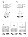
- FIG. 9A is a diagram of an illustrative host device attached to a peripheral device, according to one embodiment of principles described herein.
- FIG. 9B is a diagram of an illustrative host device attached to a peripheral device, according to one embodiment of principles described herein.
- FIG. 10A is a diagram of an illustrative software image, according to one embodiment of principles described herein.
- FIG. 10B is an illustrative diagram of memory usage within an embedded system, according to one embodiment of principles described herein.
- FIG. 10C is an illustrative diagram of memory usage, according to one embodiment of principles described herein.
- FIG. 11 is an illustrative flowchart showing an exemplary method of arranging features of a software image, according to one embodiment of principles described herein.
- embedded system refers to a special purpose computer or processing system designed to perform one or more dedicated functions for a host device in or with which the embedded system is contained. As noted above, embedded systems are typically included in a host device to provide the host device with specific computational and/or control capabilities.
- FIG. 1 a generalized diagram of the components of an embedded system ( 100 ) is shown.
- Embedded systems usually include one or more processors ( 102 ), memory ( 104 ), and, in various embodiments, other specialized components ( 106 ).
- the memory ( 104 ) may be used to contain software or firmware used by the processor during the operation of the embedded system. Consequently, in various embodiments, memory ( 104 ) may be made up of one or more different memory types and technologies, including both volatile and non-volatile memory units.
- memory ( 104 ) may include one or more of: random access memory (RAM), static random access memory (SRAM), dynamic random access memory (DRAM), erasable programmable read only memory (EPROM), electrically erasable programmable read only memory (EEPROM), magneto-resistive random access memory (MRAM), memory types that utilize the floating body effect, Flash memory, and other suitable memory types.
- RAM random access memory
- SRAM static random access memory
- DRAM dynamic random access memory
- EPROM erasable programmable read only memory
- EEPROM electrically erasable programmable read only memory
- MRAM magneto-resistive random access memory
- Each physical component of an embedded system is chosen to be powerful enough to perform the functions for which the embedded system is included in the host device, yet simple enough that cost is not increased by unneeded features.
- the included processor ( 102 ) may be limited in its programmability to operations needed in the functions of the embedded system.
- the memory ( 104 ) may be just large enough to allow the intended operation of the embedded system.
- the other specialized components ( 106 ) may only include those that will be used to perform the embedded system's intended set of tasks. By limiting the embedded system to a small number of tasks and specifically tailoring the system components to accomplish those tasks, an embedded system may be optimized for various desirable characteristics such as speed, stability, and low cost.
- embedded systems To execute the intended set of tasks, embedded systems follow instructions contained in memory ( 104 ).
- This software or firmware is usually developed on a general purpose computer, such as a desktop or laptop computer. Before the software can be loaded onto an embedded system, it must first be compiled, or translated into code that the embedded system can understand, and then linked into a file or object. Throughout the specification and appended claims, this file or object will be referred to as a software image. The software image can then be loaded into the memory ( 104 ) of the embedded system ( 100 ). The software image is then accessible to the embedded system processor ( 102 ) for execution of the instructions.
- FIG. 2 shows an exemplary method for loading a software image into memory.
- the embedded system e.g., 100 , FIG. 1
- the software image is loaded into the embedded memory (step 210 ).
- the embedded system ( 100 ) then begins operating (step 220 ) according to the instructions in the software image. Conventionally, the entire software image remains in embedded memory during the operation of the device.
- the remaining portion of memory not occupied by the software image may be allocated for use by the embedded system in carrying out instructions given in the software image.
- This remaining available memory is often referred to as the heap or the free store.
- the amount of memory required by an embedded system is not only dependent on the size of the software image, but also on the amount of memory needed by the processor to store needed data resulting from execution of the software image.
- This data may include both intermediate data generated during the execution of the software image and data resulting from running the software image that will be needed by the host device.
- a software image may contain both programming instructions and data that are used for the operation of the embedded system.
- the software image may be divisible into separate software features, where each feature is a modular unit containing instructions and data used in a given task or in conjunction with a given piece of hardware.
- These software features may include, but are not limited to, software code to support various versions of embedded operating systems, embedded system hardware, peripherals, or host devices. For example, a given software feature may only be needed to support a specific model or embedded system hardware platform. Whenever this particular hardware platform is not being used, the system could function properly even if that software feature was not included in the software image.
- the inefficient use of memory may require that the embedded device be designed with greater amounts of memory than would otherwise by the case, leading to a higher cost to produce the embedded device. Additionally, the inefficient use of memory may also limit the ability to update the device with a larger, upgraded software image. An upgraded software image may be used to accommodate changes to a host device or the environment in which the host device operates. The inability to update the software image due to inefficient memory allocation can lead to the premature retirement of the host device.
- FIG. 3 is a flow diagram of an exemplary method for extracting unwanted software features from a software image that is loaded into memory.
- a software image is loaded into memory (step 310 ).
- the system then begins a memory recovery process. It determines which features are not needed by the system (step 320 ) and then recovers the memory dedicated to code support those unneeded features (step 330 ). This recovered memory may then be allocated to the system heap, upgraded software, or other memory task.
- the normal operation of the system may then begin (step 340 ).
- Determining which features are not needed may be done based on many factors. For example, the embedded system may be instructed to remove certain software features simply based on the serial number of the embedded system, the identity of the host device, or based on peripheral hardware to which the host device is connected. For example, the embedded system may compare its host's identifier to a list which indicates which software features are required for the function of that specific host. Other software features can be discarded and the memory recovered for other uses. In this manner, an embedded system can optimize the allocation of memory to store only the software features that specifically apply to its own operation.
- FIG. 4 an illustrative block of memory ( 400 ) within an embedded device is shown.
- This block of memory ( 400 ) is generally divided into two segments: a first segment which stores the software image and a second segment which is used by the processor as it executes the instructions contained within the software image.
- the maximum allowable image size must be limited such that there is sufficient uncommitted memory available to execute the instructions contained in the software image. This remaining memory is allocated to a system heap that is used by the processor during execution of the software image.
- brackets indicate the amount of memory needed for the heap ( 410 ) and the resulting maximum conventional image size ( 420 ).
- the initial size of the image may be increased up to a point where only an amount of memory needed ( 430 ) to perform the memory recovery process is left. This assumes that the memory recovery process will reduce the initial image size ( 440 ) sufficiently to accommodate the head ( 410 ) during subsequent system operation.
- the new maximum image size ( 440 ) of the software image, prior to memory recovery may be much larger than the conventional maximum image size ( 420 ). This allows an initial software image written to support multiple host versions, for example, to be larger, knowing that the features unneeded by the host in which the image is deployed will be extracted to accommodate the heap by the memory recovery process ( 430 ).
- FIG. 5A a diagram of an illustrative network of electronic devices ( 500 ) is shown.
- the network ( 500 ) consists of a control device ( 510 ) connected to a host device ( 520 ).
- the host device ( 520 ) contains an embedded system ( 530 ).
- the host device ( 520 ) is a random access memory (RAM) only device, meaning that it does not have long-term memory storage.
- the control device ( 510 ) stores the software image required for the operation of the host device A ( 520 ).
- FIG. 5B shows a block of RAM ( 522 ) representing the total RAM in the embedded system ( 530 ).
- the image ( 502 ) has been loaded into memory and the remaining RAM ( 524 ) is available for use as the system heap.
- the remaining memory ( 524 ) exceeds the minimum heap size ( 532 ), allowing the embedded system A ( 530 ) to execute the commands contained in the software image ( 502 ).
- FIG. 6 shows an illustrative diagram of an expanded network of electronic devices ( 600 ).
- This expanded network includes a second host device ( 620 ) containing a second embedded system ( 630 ).
- both host devices ( 520 , 620 ) are RAM-only devices.
- the second host device ( 620 ) has more RAM in its embedded system and additional hardware.
- the additional hardware on the second host device ( 620 ) requires additional software to be included in the software image.
- An alternative to a larger software image may be the use of two software images.
- the system ( 600 ) may not be configured to distribute multiple software images.
- the control device ( 510 ) may not have enough memory to hold the additional image.
- the control device, the network, or the host devices may not be configured to manage multiple software images.
- the first host device ( 520 ) may not be configured to differentiate between a first software image and a second software image sent over the network.
- the manufacturer of the host device and embedded system may provide and support only one “universal” software image. For these and other reasons, it can be desirable to configure an embedded system to recover memory from unneeded features.
- FIG. 7 represents a block of RAM ( 700 ) on the second host controller ( 620 ).
- the block of RAM ( 700 ) on the second host controller ( 620 ) is significantly larger than the block of RAM ( 522 ) on first host device ( 520 ).
- An updated software image ( 502 , 704 ) is loaded into the block of RAM ( 700 ).
- the updated software image comprises a first block ( 502 ) that includes the software in the original software image and a second block ( 704 ) that includes the software required to support the new embedded system ( 630 ). Because there is enough remaining memory ( 702 ) to meet the requirements of the heap and both memory blocks ( 502 , 704 ) are needed for proper operation of the device, neither of the blocks will be removed during the memory recovery process.
- FIG. 8A shows the block of RAM ( 522 ) contained within the first embedded system ( 530 , FIG. 6 ) with the new software image ( 502 , 704 ) loaded.
- the embedded system 530 , FIG. 6
- the embedded system does not have enough memory available for the heap to execute the instructions in the software image ( 502 , 704 ).
- FIG. 8B shows the block of RAM ( 522 ) in the first embedded system ( 530 , FIG. 6 ) after the unneeded block ( 704 ) of the software image is recovered.
- FIGS. 9A and 9B show two different configurations of an electronic system ( 900 ) which includes a host device ( 902 ) configured to connect to a number of peripherals and an embedded system ( 904 ) which supports the functionality of the host device ( 902 ).
- the host device ( 902 ) contains long-term storage memory which allows a software image to be stored locally on the host device ( 902 ). The software image is then transferred into RAM contained within the embedded device ( 904 ).
- the host device ( 902 ) is connected to a type 1 peripheral ( 906 ).
- FIG. 9B the host device ( 902 ) is connected to a type 2 peripheral ( 908 ).
- the two types of peripherals ( 906 , 908 ) expand the functionality of the system in different ways and require different software features for proper operation.
- FIG. 10A shows a diagram of an exemplary software image ( 1000 ) for the embedded system ( 904 ).
- This software image ( 1000 ) consists of a first block ( 1010 ), a second block ( 1020 ), and a third block ( 1030 ).
- the first block ( 1010 ) contains software code that will be required by the device ( 900 ) regardless of the type of peripheral it supports. It may contain, for example, operating system code and memory recovery code.
- the second block ( 1020 ) contains code to support the operation of the type 1 peripheral ( 906 ).
- the third memory block ( 1030 ) contains code to support the operation of the type 2 peripheral ( 908 ).
- FIG. 10B shows the RAM usage of the embedded system ( 904 ) when it is connected to the type 1 peripheral ( 906 , FIG. 9A ) and the memory recovery process has finished.
- the third block ( 1030 ) of the software image ( 1000 ) was released because the device did not need to support the type 2 peripheral ( 908 , FIG. 9B ).
- the remaining memory ( 1040 ) can then be allocated to the heap.
- FIG. 10C shows the RAM usage of the embedded system ( 904 ) when it is connected to the type 2 peripheral ( 908 , FIG. 9B ) and the memory recovery process has finished.
- the second memory block ( 1020 ) of the software image ( 1000 ) was released because the embedded system ( 904 ) did not need to support the type 1 peripheral.
- the released memory ( 1044 ) can then be allocated to the heap.
- the free memory ( 1042 , 1044 ) is not a contiguous block of memory. This leads to a split heap configuration. Split heaps will be discussed below in further detail.
- the instructions and data that enable the recovery of memory dedicated to unneeded feature are contained within the software image.
- the system in order to remove unneeded software features resident in the embedded system memory, the system must know where the features reside in memory. A log of these feature locations may be made and included in the software image. Then, when it is determined that a feature is unneeded, those memory locations can be released and allocated for use by the system heap.
- the software image may also contain instructions for determining which features are unneeded and how to release their memory locations. Consequently, in some embodiments, an updated image may be all that is necessary to enable this method, even on older embedded systems.
- releasing software features can result in a fragmentation of free memory.
- This fragmented free memory may be less useful than larger contiguous blocks of free memory.
- the location of features in memory is not controlled.
- the features, and even multiple portions of a single feature may be distributed throughout the software image. If the memory for this feature is recovered, this may result in a severely fragmented heap.
- a split heap may be used, a contiguous heap may be more efficient and useful than a heap split into two or more parts.
- the software image can be modified so that the various software features are loaded into memory in a certain order or memory location.
- the software image is typically loaded onto the embedded system memory beginning with the lowest memory address and continuing until the complete software image is loaded.
- the amount of free memory fragmentation can be minimized. If, for example, a particular feature is the most likely to be released by the system, it could be placed at the top of the image so that, if released, the memory it occupied can be contiguously incorporated into the system heap. On the other hand, there may often be a software feature that will never be released. Therefore, placing this software feature at the bottom of the image may reduce the fragmentation of the heap. Additionally, software features that are likely to be released together can be grouped to reduce fragmentation. Custom linker scripts may be used to place the features in the desired order and in the desire grouping.
- FIG. 11 shows a flow chart of an illustrative method for creating a software image.
- a designer begins creating a software image by making a list of all the software features that will need to be included in the image (step 1100 ).
- the included software features will depend, in part, on the embedded systems for which the image is targeted and hardware that needs to be supported.
- features can be ranked in order of descending likelihood of being removed. For example, certain features, such as the operating system, may never be removed by any of the target embedded systems. Such features could be placed at the bottom of the list, meaning that they are stored in memory away from the area that will generally contain the heap. If there are features with approximately equal likelihood of being removed, those most likely to be removed together could be placed next to each other on the list (step 1120 ). This could lead to the release of greater contiguous portions of memory and minimize the fragmentation of free memory. At this point, any other considerations of efficiency can be taken into account. These considerations could include limits imposed by the particular linking process or the operating system to be used.
- step 1130 When the features are satisfactorily organized, instructions for the removal of unwanted features may be written (step 1130 ). Next, the features may be compiled and linked (step 1140 ) into the order determined in the previous steps. This will most likely be done with linker scripts as default linkers will not generally put the features in the above discussed order. After completion of any additional tasks, the software image may be written to the embedded device.
Abstract
Description
Claims (19)
Priority Applications (1)
| Application Number | Priority Date | Filing Date | Title |
|---|---|---|---|
| US12/147,271 US8108645B2 (en) | 2008-06-26 | 2008-06-26 | Optimized memory allocation via feature extraction |
Applications Claiming Priority (1)
| Application Number | Priority Date | Filing Date | Title |
|---|---|---|---|
| US12/147,271 US8108645B2 (en) | 2008-06-26 | 2008-06-26 | Optimized memory allocation via feature extraction |
Publications (2)
| Publication Number | Publication Date |
|---|---|
| US20090327639A1 US20090327639A1 (en) | 2009-12-31 |
| US8108645B2 true US8108645B2 (en) | 2012-01-31 |
Family
ID=41448969
Family Applications (1)
| Application Number | Title | Priority Date | Filing Date |
|---|---|---|---|
| US12/147,271 Active - Reinstated 2030-11-01 US8108645B2 (en) | 2008-06-26 | 2008-06-26 | Optimized memory allocation via feature extraction |
Country Status (1)
| Country | Link |
|---|---|
| US (1) | US8108645B2 (en) |
Cited By (1)
| Publication number | Priority date | Publication date | Assignee | Title |
|---|---|---|---|---|
| US10572451B2 (en) | 2014-01-31 | 2020-02-25 | Hewlett Packard Enterprise Development Lp | File system storage |
Families Citing this family (1)
| Publication number | Priority date | Publication date | Assignee | Title |
|---|---|---|---|---|
| WO2023062221A1 (en) | 2021-10-15 | 2023-04-20 | Volkswagen Aktiengesellschaft | Method and system for stripping down a software to minimize its code for operating device features of a device |
Citations (16)
| Publication number | Priority date | Publication date | Assignee | Title |
|---|---|---|---|---|
| US6247175B1 (en) * | 1998-12-22 | 2001-06-12 | Nortel Networks Limited | Method and apparatus for identifying and removing unused software procedures |
| US6282621B1 (en) * | 1995-05-31 | 2001-08-28 | Microsoft Corporation | Method and apparatus for reclaiming memory |
| US20020023196A1 (en) * | 2000-08-21 | 2002-02-21 | Nec Corporation | Program module management system and method thereof and storing medium of management programs of the system |
| US20040064808A1 (en) * | 2002-09-30 | 2004-04-01 | Fujitsu Limited | Storage medium storing program directing computer to control optimization of program, and program optimizing apparatus |
| US20050097546A1 (en) * | 2003-10-30 | 2005-05-05 | International Business Machines Corporation | Ordering of high use program code segments using simulated annealing |
| US20060048138A1 (en) * | 2004-09-02 | 2006-03-02 | International Business Machines Corporation | System, method, and program for resizing an install image |
| US20070283328A1 (en) * | 2006-05-31 | 2007-12-06 | Taimur Javed | Computer code partitioning for enhanced performance |
| US20070294683A1 (en) * | 2006-06-15 | 2007-12-20 | Samsung Electronics Co., Ltd. | Methods of generating, linking and updating component-based software and information storage medium having such software recorded thereon |
| US20080133598A1 (en) * | 2006-11-30 | 2008-06-05 | Clark Williams | Development tool for footprint reduction |
| US20080184220A1 (en) * | 2000-11-17 | 2008-07-31 | Shao-Chun Chen | Initialzation and update of software and/or firmware in electronic devices |
| US20090113444A1 (en) * | 2007-10-31 | 2009-04-30 | Google Inc. | Application Management |
| US20090249313A1 (en) * | 2008-03-31 | 2009-10-01 | Sobel William E | System and Method for Prioritizing the Compilation of Bytecode Modules During Installation of a Software Application |
| US7610366B2 (en) * | 2001-11-06 | 2009-10-27 | Canon Kabushiki Kaisha | Dynamic network device reconfiguration |
| US20090307673A1 (en) * | 2007-09-26 | 2009-12-10 | Eichenberger Alexandre E | System and Method for Domain Stretching for an Advanced Dual-Representation Polyhedral Loop Transformation Framework |
| US20100175053A1 (en) * | 2007-06-21 | 2010-07-08 | Nxp B.V. | Device and a method of managing a plurality of software items |
| US7765541B1 (en) * | 2004-05-26 | 2010-07-27 | Oracle America, Inc. | Minimization methodology |
-
2008
- 2008-06-26 US US12/147,271 patent/US8108645B2/en active Active - Reinstated
Patent Citations (16)
| Publication number | Priority date | Publication date | Assignee | Title |
|---|---|---|---|---|
| US6282621B1 (en) * | 1995-05-31 | 2001-08-28 | Microsoft Corporation | Method and apparatus for reclaiming memory |
| US6247175B1 (en) * | 1998-12-22 | 2001-06-12 | Nortel Networks Limited | Method and apparatus for identifying and removing unused software procedures |
| US20020023196A1 (en) * | 2000-08-21 | 2002-02-21 | Nec Corporation | Program module management system and method thereof and storing medium of management programs of the system |
| US20080184220A1 (en) * | 2000-11-17 | 2008-07-31 | Shao-Chun Chen | Initialzation and update of software and/or firmware in electronic devices |
| US7610366B2 (en) * | 2001-11-06 | 2009-10-27 | Canon Kabushiki Kaisha | Dynamic network device reconfiguration |
| US20040064808A1 (en) * | 2002-09-30 | 2004-04-01 | Fujitsu Limited | Storage medium storing program directing computer to control optimization of program, and program optimizing apparatus |
| US20050097546A1 (en) * | 2003-10-30 | 2005-05-05 | International Business Machines Corporation | Ordering of high use program code segments using simulated annealing |
| US7765541B1 (en) * | 2004-05-26 | 2010-07-27 | Oracle America, Inc. | Minimization methodology |
| US20060048138A1 (en) * | 2004-09-02 | 2006-03-02 | International Business Machines Corporation | System, method, and program for resizing an install image |
| US20070283328A1 (en) * | 2006-05-31 | 2007-12-06 | Taimur Javed | Computer code partitioning for enhanced performance |
| US20070294683A1 (en) * | 2006-06-15 | 2007-12-20 | Samsung Electronics Co., Ltd. | Methods of generating, linking and updating component-based software and information storage medium having such software recorded thereon |
| US20080133598A1 (en) * | 2006-11-30 | 2008-06-05 | Clark Williams | Development tool for footprint reduction |
| US20100175053A1 (en) * | 2007-06-21 | 2010-07-08 | Nxp B.V. | Device and a method of managing a plurality of software items |
| US20090307673A1 (en) * | 2007-09-26 | 2009-12-10 | Eichenberger Alexandre E | System and Method for Domain Stretching for an Advanced Dual-Representation Polyhedral Loop Transformation Framework |
| US20090113444A1 (en) * | 2007-10-31 | 2009-04-30 | Google Inc. | Application Management |
| US20090249313A1 (en) * | 2008-03-31 | 2009-10-01 | Sobel William E | System and Method for Prioritizing the Compilation of Bytecode Modules During Installation of a Software Application |
Cited By (1)
| Publication number | Priority date | Publication date | Assignee | Title |
|---|---|---|---|---|
| US10572451B2 (en) | 2014-01-31 | 2020-02-25 | Hewlett Packard Enterprise Development Lp | File system storage |
Also Published As
| Publication number | Publication date |
|---|---|
| US20090327639A1 (en) | 2009-12-31 |
Similar Documents
| Publication | Publication Date | Title |
|---|---|---|
| US7017004B1 (en) | System and method for updating contents of a flash ROM | |
| US9507581B2 (en) | Systems and methods of device firmware delivery for pre-boot updates | |
| CN101937340B (en) | Method and device for dynamically updating and controlling software by using patches | |
| US7363484B2 (en) | Apparatus and method for selectively mapping proper boot image to processors of heterogeneous computer systems | |
| CN102165422B (en) | Firmware update device and method | |
| JP5757509B2 (en) | System reset | |
| CN103970557B (en) | The method and storage device of storage device activation system | |
| EP2333667A1 (en) | Firmware updating system, firmware delivering server, firmware incorporating device, and program | |
| EP1873638A1 (en) | Portable apparatus supporting multiple operating systems and supporting method therefor | |
| CN107566169B (en) | Firmware upgrading method based on openwrt and router | |
| KR20050061378A (en) | Applying custom software image updates to non-volatile storage in a failsafe manner | |
| CN110096300B (en) | FPGA program file backup management system, operation method and upgrading method | |
| US10579300B2 (en) | Information handling system firmware persistent memory runtime reclaim | |
| CN102629206A (en) | Embedded system software upgrading method and system | |
| US20060224874A1 (en) | Method for updating system management basic input output system (SMBIOS) data | |
| CN101923473A (en) | Embedded electronic device and method for updating firmware thereof | |
| US20140372710A1 (en) | System and method for recovering from an unexpected shutdown in a write-back caching environment | |
| CN104424140A (en) | Unified extensible firmware interface (uefi) driver | |
| EP1614034B1 (en) | Initialization and update of software and/or firmware in electronic devices | |
| KR20090055074A (en) | Method of transaction-based firmware upgrade in mobile telephone and firmware upgrade system thereof | |
| US6745324B1 (en) | Dynamic firmware image creation from an object file stored in a reserved area of a data storage device of a redundant array of independent disks (RAID) system | |
| US8108645B2 (en) | Optimized memory allocation via feature extraction | |
| CN111133419B (en) | Stack security for independently defined operations | |
| US20060026415A1 (en) | Method of updating a portion BIOS | |
| CN111694580B (en) | Method and device for upgrading and initializing storage device and electronic device |
Legal Events
| Date | Code | Title | Description |
|---|---|---|---|
| AS | Assignment |
Owner name: HEWLETT-PACKARD DEVELOPMENT COMPANY, L.P., TEXAS Free format text: ASSIGNMENT OF ASSIGNORS INTEREST;ASSIGNORS:BRODEUR, ROBERT R.;NEBEKER, ROBERT A.;LEE, CHENG NAM;REEL/FRAME:021167/0195;SIGNING DATES FROM 20080624 TO 20080626 Owner name: HEWLETT-PACKARD DEVELOPMENT COMPANY, L.P., TEXAS Free format text: ASSIGNMENT OF ASSIGNORS INTEREST;ASSIGNORS:BRODEUR, ROBERT R.;NEBEKER, ROBERT A.;LEE, CHENG NAM;SIGNING DATES FROM 20080624 TO 20080626;REEL/FRAME:021167/0195 |
|
| STCF | Information on status: patent grant |
Free format text: PATENTED CASE |
|
| CC | Certificate of correction | ||
| FPAY | Fee payment |
Year of fee payment: 4 |
|
| AS | Assignment |
Owner name: HEWLETT PACKARD ENTERPRISE DEVELOPMENT LP, TEXAS Free format text: ASSIGNMENT OF ASSIGNORS INTEREST;ASSIGNOR:HEWLETT-PACKARD DEVELOPMENT COMPANY, L.P.;REEL/FRAME:037079/0001 Effective date: 20151027 |
|
| FEPP | Fee payment procedure |
Free format text: MAINTENANCE FEE REMINDER MAILED (ORIGINAL EVENT CODE: REM.); ENTITY STATUS OF PATENT OWNER: LARGE ENTITY |
|
| LAPS | Lapse for failure to pay maintenance fees |
Free format text: PATENT EXPIRED FOR FAILURE TO PAY MAINTENANCE FEES (ORIGINAL EVENT CODE: EXP.); ENTITY STATUS OF PATENT OWNER: LARGE ENTITY |
|
| FP | Lapsed due to failure to pay maintenance fee |
Effective date: 20200131 |
|
| PRDP | Patent reinstated due to the acceptance of a late maintenance fee |
Effective date: 20200819 |
|
| FEPP | Fee payment procedure |
Free format text: PETITION RELATED TO MAINTENANCE FEES FILED (ORIGINAL EVENT CODE: PMFP); ENTITY STATUS OF PATENT OWNER: LARGE ENTITY Free format text: SURCHARGE, PETITION TO ACCEPT PYMT AFTER EXP, UNINTENTIONAL (ORIGINAL EVENT CODE: M1558); ENTITY STATUS OF PATENT OWNER: LARGE ENTITY Free format text: PETITION RELATED TO MAINTENANCE FEES GRANTED (ORIGINAL EVENT CODE: PMFG); ENTITY STATUS OF PATENT OWNER: LARGE ENTITY |
|
| MAFP | Maintenance fee payment |
Free format text: PAYMENT OF MAINTENANCE FEE, 8TH YEAR, LARGE ENTITY (ORIGINAL EVENT CODE: M1552); ENTITY STATUS OF PATENT OWNER: LARGE ENTITY Year of fee payment: 8 |
|
| STCF | Information on status: patent grant |
Free format text: PATENTED CASE |
|
| AS | Assignment |
Owner name: OT PATENT ESCROW, LLC, ILLINOIS Free format text: PATENT ASSIGNMENT, SECURITY INTEREST, AND LIEN AGREEMENT;ASSIGNORS:HEWLETT PACKARD ENTERPRISE DEVELOPMENT LP;HEWLETT PACKARD ENTERPRISE COMPANY;REEL/FRAME:055269/0001 Effective date: 20210115 |
|
| AS | Assignment |
Owner name: VALTRUS INNOVATIONS LIMITED, IRELAND Free format text: ASSIGNMENT OF ASSIGNORS INTEREST;ASSIGNOR:OT PATENT ESCROW, LLC;REEL/FRAME:059058/0720 Effective date: 20220202 |
|
| MAFP | Maintenance fee payment |
Free format text: PAYMENT OF MAINTENANCE FEE, 12TH YEAR, LARGE ENTITY (ORIGINAL EVENT CODE: M1553); ENTITY STATUS OF PATENT OWNER: LARGE ENTITY Year of fee payment: 12 |