US8850348B2 - Dynamic device-associated feedback indicative of responsible device usage - Google Patents
Dynamic device-associated feedback indicative of responsible device usage Download PDFInfo
- Publication number
- US8850348B2 US8850348B2 US13/632,118 US201213632118A US8850348B2 US 8850348 B2 US8850348 B2 US 8850348B2 US 201213632118 A US201213632118 A US 201213632118A US 8850348 B2 US8850348 B2 US 8850348B2
- Authority
- US
- United States
- Prior art keywords
- energy usage
- temperature
- setpoint temperature
- user
- feedback
- Prior art date
- Legal status (The legal status is an assumption and is not a legal conclusion. Google has not performed a legal analysis and makes no representation as to the accuracy of the status listed.)
- Active
Links
Images


Classifications
-
- F—MECHANICAL ENGINEERING; LIGHTING; HEATING; WEAPONS; BLASTING
- F24—HEATING; RANGES; VENTILATING
- F24F—AIR-CONDITIONING; AIR-HUMIDIFICATION; VENTILATION; USE OF AIR CURRENTS FOR SCREENING
- F24F11/00—Control or safety arrangements
- F24F11/62—Control or safety arrangements characterised by the type of control or by internal processing, e.g. using fuzzy logic, adaptive control or estimation of values
-
- F—MECHANICAL ENGINEERING; LIGHTING; HEATING; WEAPONS; BLASTING
- F24—HEATING; RANGES; VENTILATING
- F24F—AIR-CONDITIONING; AIR-HUMIDIFICATION; VENTILATION; USE OF AIR CURRENTS FOR SCREENING
- F24F11/00—Control or safety arrangements
- F24F11/30—Control or safety arrangements for purposes related to the operation of the system, e.g. for safety or monitoring
- F24F11/46—Improving electric energy efficiency or saving
- F24F11/47—Responding to energy costs
-
- F—MECHANICAL ENGINEERING; LIGHTING; HEATING; WEAPONS; BLASTING
- F24—HEATING; RANGES; VENTILATING
- F24F—AIR-CONDITIONING; AIR-HUMIDIFICATION; VENTILATION; USE OF AIR CURRENTS FOR SCREENING
- F24F11/00—Control or safety arrangements
- F24F11/50—Control or safety arrangements characterised by user interfaces or communication
- F24F11/52—Indication arrangements, e.g. displays
- F24F11/523—Indication arrangements, e.g. displays for displaying temperature data
-
- F—MECHANICAL ENGINEERING; LIGHTING; HEATING; WEAPONS; BLASTING
- F24—HEATING; RANGES; VENTILATING
- F24F—AIR-CONDITIONING; AIR-HUMIDIFICATION; VENTILATION; USE OF AIR CURRENTS FOR SCREENING
- F24F11/00—Control or safety arrangements
- F24F11/50—Control or safety arrangements characterised by user interfaces or communication
- F24F11/56—Remote control
- F24F11/58—Remote control using Internet communication
-
- F—MECHANICAL ENGINEERING; LIGHTING; HEATING; WEAPONS; BLASTING
- F24—HEATING; RANGES; VENTILATING
- F24F—AIR-CONDITIONING; AIR-HUMIDIFICATION; VENTILATION; USE OF AIR CURRENTS FOR SCREENING
- F24F11/00—Control or safety arrangements
- F24F11/50—Control or safety arrangements characterised by user interfaces or communication
- F24F11/56—Remote control
- F24F11/59—Remote control for presetting
-
- F—MECHANICAL ENGINEERING; LIGHTING; HEATING; WEAPONS; BLASTING
- F24—HEATING; RANGES; VENTILATING
- F24F—AIR-CONDITIONING; AIR-HUMIDIFICATION; VENTILATION; USE OF AIR CURRENTS FOR SCREENING
- F24F11/00—Control or safety arrangements
- F24F11/62—Control or safety arrangements characterised by the type of control or by internal processing, e.g. using fuzzy logic, adaptive control or estimation of values
- F24F11/63—Electronic processing
- F24F11/64—Electronic processing using pre-stored data
-
- F—MECHANICAL ENGINEERING; LIGHTING; HEATING; WEAPONS; BLASTING
- F24—HEATING; RANGES; VENTILATING
- F24F—AIR-CONDITIONING; AIR-HUMIDIFICATION; VENTILATION; USE OF AIR CURRENTS FOR SCREENING
- F24F11/00—Control or safety arrangements
- F24F11/89—Arrangement or mounting of control or safety devices
-
- G—PHYSICS
- G05—CONTROLLING; REGULATING
- G05B—CONTROL OR REGULATING SYSTEMS IN GENERAL; FUNCTIONAL ELEMENTS OF SUCH SYSTEMS; MONITORING OR TESTING ARRANGEMENTS FOR SUCH SYSTEMS OR ELEMENTS
- G05B19/00—Programme-control systems
- G05B19/02—Programme-control systems electric
- G05B19/18—Numerical control [NC], i.e. automatically operating machines, in particular machine tools, e.g. in a manufacturing environment, so as to execute positioning, movement or co-ordinated operations by means of programme data in numerical form
- G05B19/409—Numerical control [NC], i.e. automatically operating machines, in particular machine tools, e.g. in a manufacturing environment, so as to execute positioning, movement or co-ordinated operations by means of programme data in numerical form characterised by using manual input [MDI] or by using control panel, e.g. controlling functions with the panel; characterised by control panel details, by setting parameters
-
- G—PHYSICS
- G05—CONTROLLING; REGULATING
- G05D—SYSTEMS FOR CONTROLLING OR REGULATING NON-ELECTRIC VARIABLES
- G05D23/00—Control of temperature
- G05D23/19—Control of temperature characterised by the use of electric means
- G05D23/1902—Control of temperature characterised by the use of electric means characterised by the use of a variable reference value
- G05D23/1905—Control of temperature characterised by the use of electric means characterised by the use of a variable reference value associated with tele control
-
- G—PHYSICS
- G06—COMPUTING; CALCULATING OR COUNTING
- G06F—ELECTRIC DIGITAL DATA PROCESSING
- G06F3/00—Input arrangements for transferring data to be processed into a form capable of being handled by the computer; Output arrangements for transferring data from processing unit to output unit, e.g. interface arrangements
- G06F3/01—Input arrangements or combined input and output arrangements for interaction between user and computer
- G06F3/03—Arrangements for converting the position or the displacement of a member into a coded form
- G06F3/033—Pointing devices displaced or positioned by the user, e.g. mice, trackballs, pens or joysticks; Accessories therefor
- G06F3/0362—Pointing devices displaced or positioned by the user, e.g. mice, trackballs, pens or joysticks; Accessories therefor with detection of 1D translations or rotations of an operating part of the device, e.g. scroll wheels, sliders, knobs, rollers or belts
-
- G—PHYSICS
- G06—COMPUTING; CALCULATING OR COUNTING
- G06F—ELECTRIC DIGITAL DATA PROCESSING
- G06F3/00—Input arrangements for transferring data to be processed into a form capable of being handled by the computer; Output arrangements for transferring data from processing unit to output unit, e.g. interface arrangements
- G06F3/01—Input arrangements or combined input and output arrangements for interaction between user and computer
- G06F3/048—Interaction techniques based on graphical user interfaces [GUI]
- G06F3/0484—Interaction techniques based on graphical user interfaces [GUI] for the control of specific functions or operations, e.g. selecting or manipulating an object, an image or a displayed text element, setting a parameter value or selecting a range
- G06F3/04847—Interaction techniques to control parameter settings, e.g. interaction with sliders or dials
-
- G—PHYSICS
- G09—EDUCATION; CRYPTOGRAPHY; DISPLAY; ADVERTISING; SEALS
- G09G—ARRANGEMENTS OR CIRCUITS FOR CONTROL OF INDICATING DEVICES USING STATIC MEANS TO PRESENT VARIABLE INFORMATION
- G09G5/00—Control arrangements or circuits for visual indicators common to cathode-ray tube indicators and other visual indicators
- G09G5/36—Control arrangements or circuits for visual indicators common to cathode-ray tube indicators and other visual indicators characterised by the display of a graphic pattern, e.g. using an all-points-addressable [APA] memory
- G09G5/37—Details of the operation on graphic patterns
-
- F—MECHANICAL ENGINEERING; LIGHTING; HEATING; WEAPONS; BLASTING
- F24—HEATING; RANGES; VENTILATING
- F24F—AIR-CONDITIONING; AIR-HUMIDIFICATION; VENTILATION; USE OF AIR CURRENTS FOR SCREENING
- F24F11/00—Control or safety arrangements
- F24F11/30—Control or safety arrangements for purposes related to the operation of the system, e.g. for safety or monitoring
- F24F11/46—Improving electric energy efficiency or saving
-
- F—MECHANICAL ENGINEERING; LIGHTING; HEATING; WEAPONS; BLASTING
- F24—HEATING; RANGES; VENTILATING
- F24F—AIR-CONDITIONING; AIR-HUMIDIFICATION; VENTILATION; USE OF AIR CURRENTS FOR SCREENING
- F24F11/00—Control or safety arrangements
- F24F11/50—Control or safety arrangements characterised by user interfaces or communication
- F24F11/52—Indication arrangements, e.g. displays
-
- F—MECHANICAL ENGINEERING; LIGHTING; HEATING; WEAPONS; BLASTING
- F24—HEATING; RANGES; VENTILATING
- F24F—AIR-CONDITIONING; AIR-HUMIDIFICATION; VENTILATION; USE OF AIR CURRENTS FOR SCREENING
- F24F11/00—Control or safety arrangements
- F24F11/50—Control or safety arrangements characterised by user interfaces or communication
- F24F11/56—Remote control
-
- F—MECHANICAL ENGINEERING; LIGHTING; HEATING; WEAPONS; BLASTING
- F24—HEATING; RANGES; VENTILATING
- F24F—AIR-CONDITIONING; AIR-HUMIDIFICATION; VENTILATION; USE OF AIR CURRENTS FOR SCREENING
- F24F2120/00—Control inputs relating to users or occupants
-
- F—MECHANICAL ENGINEERING; LIGHTING; HEATING; WEAPONS; BLASTING
- F24—HEATING; RANGES; VENTILATING
- F24F—AIR-CONDITIONING; AIR-HUMIDIFICATION; VENTILATION; USE OF AIR CURRENTS FOR SCREENING
- F24F2120/00—Control inputs relating to users or occupants
- F24F2120/20—Feedback from users
-
- G—PHYSICS
- G05—CONTROLLING; REGULATING
- G05B—CONTROL OR REGULATING SYSTEMS IN GENERAL; FUNCTIONAL ELEMENTS OF SUCH SYSTEMS; MONITORING OR TESTING ARRANGEMENTS FOR SUCH SYSTEMS OR ELEMENTS
- G05B2219/00—Program-control systems
- G05B2219/20—Pc systems
- G05B2219/26—Pc applications
- G05B2219/2614—HVAC, heating, ventillation, climate control
-
- G—PHYSICS
- G06—COMPUTING; CALCULATING OR COUNTING
- G06F—ELECTRIC DIGITAL DATA PROCESSING
- G06F3/00—Input arrangements for transferring data to be processed into a form capable of being handled by the computer; Output arrangements for transferring data from processing unit to output unit, e.g. interface arrangements
- G06F3/01—Input arrangements or combined input and output arrangements for interaction between user and computer
- G06F3/048—Interaction techniques based on graphical user interfaces [GUI]
- G06F3/0481—Interaction techniques based on graphical user interfaces [GUI] based on specific properties of the displayed interaction object or a metaphor-based environment, e.g. interaction with desktop elements like windows or icons, or assisted by a cursor's changing behaviour or appearance
- G06F3/04817—Interaction techniques based on graphical user interfaces [GUI] based on specific properties of the displayed interaction object or a metaphor-based environment, e.g. interaction with desktop elements like windows or icons, or assisted by a cursor's changing behaviour or appearance using icons
-
- G—PHYSICS
- G09—EDUCATION; CRYPTOGRAPHY; DISPLAY; ADVERTISING; SEALS
- G09G—ARRANGEMENTS OR CIRCUITS FOR CONTROL OF INDICATING DEVICES USING STATIC MEANS TO PRESENT VARIABLE INFORMATION
- G09G2320/00—Control of display operating conditions
- G09G2320/06—Adjustment of display parameters
- G09G2320/0613—The adjustment depending on the type of the information to be displayed
Definitions
- This patent specification relates to systems, methods, and related computer program products for presenting feedback to users to indicate whether the users' usage behaviors are responsible (e.g., with regard to environmental, fiscal or health concerns). More particularly, this patent specification relates to a dynamic presenting feedback (e.g., via one or more visual icons) on a device itself or an interface tied to the device (e.g., a web-based or smart-device interface that can control the device) that identifies desirable changes to device settings.
- a dynamic presenting feedback e.g., via one or more visual icons
- thermostats can be used to control home temperatures
- refrigerators can be used to control refrigerating temperatures
- light switches can be used to control light power states and intensities.
- Extreme operation of the devices can frequently lead to immediate user satisfaction. For example, users can enjoy bright lights, warm temperatures in the winter, and very cold refrigerator temperatures. Unfortunately, the extreme operation can result in deleterious costs. Excess energy can be used, which can contribute to harmful environmental consequences. Further, device parts' (e.g., light bulbs' or fluids') life cycles can be shortened, which can result in excess waste.
- these costs are ultimately shouldered by users. Users may experience high electricity bills or may need to purchase parts frequently. Unfortunately, these user-shouldered costs are often time-separated from the behaviors that led to them. Further, the costs are often not tied to particular behaviors, but rather to a group of behaviors over a time span. Thus, users may not fully appreciate which particular behaviors most contributed to the costs. Further, unless users have experimented with different behavior patterns, they may be unaware of the extent to which their behavior can influence the experienced costs. Therefore, users can continue to obliviously operate devices irresponsibly, thereby imposing higher costs on themselves and on the environment.
- the feedback can be instantaneous and/or delayed.
- the feedback can be presented immediately responsive to a setting change made by a user or learned based on a user's behavior over a time period. For example, if a user lowers a thermostat setpoint temperature in the winter by a sufficient amount and/or to a sufficiently low temperature, a positive indicator can be instantly presented on the thermostat.
- the thermostat learns that the user can accept a lower temperature at night in the winter than a previous setpoint temperature
- an icon can be immediately presented during one or more subsequent nights.
- the feedback can summarize whether or a degree to which a user's device settings behavior was responsible or desirable over a time period (e.g., over the course of a day).
- the feedback can be presented based on relative or absolute criteria.
- Relative criteria can indicate that, e.g., positive feedback should be presented when a user's behavior has improved relative to the user's past behavior. This can encourage a given user to consistently improve how responsibly the device is being used.
- Absolute criteria can indicate that positive feedback should always be awarded, e.g., if particular settings are received or learned. Absolute criteria can be useful in that a degree to which a user can responsibly operate a device can practically or physically saturate.
- Criteria can further be set and/or adjusted to encourage responsible use changes. Specifically, it can be advantageous to ensure that feedback is presented each user or a given fraction of the users at least a threshold percentage of the time. Users can therefore become aware of the feedback, understand that it is attainable and become motivated to attempt to achieve positive feedback. It can also be advantageous to limit the presentation of feedback to a given user or set of users. Otherwise, users can desensitize to the feedback.
- the feedback can be presented on a device itself or via interfaces tied to the device.
- a web-based or smart-device-based interface can be tied to the device.
- the interface and/or the device can allow a user to set settings on the device, view past usage patterns, and/or view usage schedules (e.g., as programmed by the user or as learned).
- the feedback is consistently presented across the device and one or more interfaces. Thus, for example, regardless as to whether a user responsibly changes a setting on a device itself or via an interface, the feedback can be instantly presented to the user.
- the interface can be configured to immediately present the feedback with respect to the influenced schedule.
- this consistent operation can require that the device and a central server reliably communicate explicit or learned setting changes such that any subsequent changes can instantly result in the appropriate feedback presentation.
- presented feedback is positive feedback.
- a user can be presented with a pleasant image, such as a green leaf, when acting responsibly.
- negative feedback e.g., a smokestack icon
- feedback can be graded or non-binary. For example, as a user's behavior approaches a desirable level, an icon can become darker or larger or more icons can appear.
- a user input mechanism that is continuously adjustable (e.g., by virtue of a rotatable ring or knob that is continuously rotatable or a slider switch that is continuously slidable), a user interface dynamic/effect/feel in which a particular degree, amount, or intensity of feedback pleasantness (for example, the visual intensity, size, etc. of the green leaf) will appear to vary continuously according to a continuous degree of greenness or responsibility represented by the continuous input being provided.
- a user interface associated with the thermostat prefferably configured such that, if the user manually actuates its continuously adjustable input component (e.g., turns a manual adjustment knob or slider) to adjust the setpoint temperature to within a certain threshold (one or two degrees F., for example) of the environmentally responsible setpoint temperature, the green leaf can start to “fade in” in appearance from being invisible to being partially visible, and then as the user continues to adjust the setpoint temperature to arrive at the environmentally responsible setpoint temperature, the green leaf becomes fully visible.
- a continuously adjustable input component e.g., turns a manual adjustment knob or slider
- this dynamic/effect has been found especially advantageous for household thermostats by synergistically harnessing the effects of (a) intrinsic visual interest in the dynamic fading or brightening of the green leaf itself, (b) stimulated user consciousness that their immediate action at that immediate point in time is affecting the environment in some way, (c) a feeling of enablement that they have the ability, by their immediate input actions, to affect the environment in a positive way, and (d) a feeling of user satisfaction that they have “done the right thing” when they achieve the full-brightness leaf.
- this synergistic combination of effects on the user psyche/emotion has the very practical and beneficial impact of causing the HVAC setpoint temperature to be more environmentally responsible than it would otherwise be, thereby causing their HVAC system to use less energy, causing their energy costs to be reduced, and furthering overall progress toward a more sustainable planet.
- disclosures herein can refer to visual feedback (e.g., icons), non-visual feedback (e.g., audial cues) can alternatively or additionally be used.
- an instant visual icon is presented to a user when the user has adjusted a setting (e.g., changing a setpoint temperature immediately, changing a scheduled setpoint temperature, setting a threshold for using various device operations, etc.) of a smart-home device in a manner that will conserve energy. Additionally, when a device learns a schedule change that will conserve energy based on a user's usage patterns, an instant visual icon is presented the next time or the next few times that the scheduled change is effected. Further, the icon can be presented within a schedule in association with the portion of the schedule responsibly changed.
- a setting e.g., changing a setpoint temperature immediately, changing a scheduled setpoint temperature, setting a threshold for using various device operations, etc.
- an overall icon can be presented to reflect instances in which a user's device setting behavior was responsible across a time period (e.g., over the course of a day).
- the overall icon presentation can be influenced by how frequently an instant icon was presented during the time period.
- a thermostat for controlling the operation of a heating, ventilation, and air conditioning (HVAC) system can be provided.
- the thermostat can include a housing and a user-interface component coupled to the housing.
- the user-interface component can include a mechanically movable input component and an electronic display, and can be configured to receive an input from a user.
- the input can be indicative of an adjustment of an HVAC-related setting and can include a continuous mechanical movement of the mechanically movable input component according to which the HVAC-related setting is correspondingly adjusted.
- the thermostat can also include a processing component coupled to the user-interface component.
- the processing component can be configured to compare on a real-time basis the HVAC-related setting that is being adjusted against a feedback criterion.
- the feedback criterion can be designed to indicate a circumstance under which feedback is to be presented to the user.
- the circumstance can be indicative of an achievement of an HVAC-related setting of a predetermined responsibility level with respect to an energy usage of the HVAC system controlled by the thermostat.
- the processing component can be further configured to determine, in real-time and based on the comparison, whether the feedback criterion is satisfied, and upon a determination that the feedback criterion is satisfied, cause visual feedback to be presented to the user in real-time.
- the real-time feedback can include a visual icon having a visual appeal corresponding to a desirability of the satisfaction of the feedback criterion.
- a method for control of an HVAC system by a thermostat can include one or more intelligent components and a display.
- the method can include receiving an input from a user, the input being indicative of an adjustment of an HVAC-related setting.
- the input can be virtual or physical movement of a part of the thermostat, such that a movement of the part of thermostat corresponds to an adjustment of the HVAC-related setting.
- the method can further include comparing on a real-time basis the HVAC-related setting that is being adjusted against a feedback criterion.
- the feedback criterion can be designed to indicate a circumstance under which feedback is to be presented to the user. The circumstance can be indicative of an achievement of a HVAC-related setting of a predetermined responsibility level with respect to an energy usage of the HVAC system controlled by the thermostat.
- the method can also include determining, in real-time and based on the comparison, whether the feedback criterion is satisfied, and upon a determination that the feedback criterion is satisfied, causing visual feedback to be presented to the user in real-time.
- the real-time feedback can include a visual icon having a visual appeal corresponding to a desirability of the satisfaction of the feedback criterion.
- a thermostat system for controlling the operation of an HVAC system.
- the thermostat system can include a user-interface component including a mechanically movable input component and an electronic display.
- the user-interface component can be configured to receive an input from a user.
- the input can be indicative of an adjustment of an HVAC-related setting and can include a non-discrete mechanical movement of the mechanically movable input component according to which the HVAC-related setting is correspondingly adjusted.
- the thermostat system can further include one or more intelligent components coupled to the user-interface component.
- the one or more intelligent components can be configured to determine the HVAC-related setting based on the detected movement of the user-interface component and compare on a real-time basis the HVAC-related setting that is being adjusted against a feedback criterion.
- the feedback criterion can be designed to indicate a circumstance under which feedback is to be presented to the user.
- the circumstance can be indicative of an achievement of a HVAC-related setting of a predetermined responsibility level with respect to an energy usage of the HVAC system controlled by the thermostat.
- the one or more intelligent components can further be configured to determine, in real-time and based on the comparison, whether the feedback criterion is satisfied, and upon a determination that the feedback criterion is satisfied, cause visual feedback to be presented to the user in real-time.
- the real-time feedback can include a visual icon having a visual appeal corresponding to a desirability of the satisfaction of the feedback criterion.
- FIG. 1 illustrates an example of general device components which can be included in an intelligent, network-connected device
- FIG. 2 illustrates an example of a smart home environment within which one or more of the devices, methods, systems, services, and/or computer program products described further herein can be applicable;
- FIG. 3 illustrates a network-level view of an extensible devices and services platform with which a smart home environment can be integrated
- FIG. 4 illustrates an abstracted functional view of the extensible devices and services platform of FIG. 3 ;
- FIG. 5 illustrates components of feedback engine according to an embodiment of the invention
- FIGS. 6A-6D show examples of an adjustable schedule 600 .
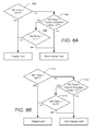
- FIGS. 7A-7G illustrate flowcharts for processes of causing device-related feedback to be presented in accordance with an embodiment of the invention
- FIGS. 8A-8F illustrate flowcharts for processes of causing device-related feedback to be presented in response to analyzing thermostat-device settings in accordance with an embodiment of the invention
- FIG. 9 illustrates series of display screens on a thermostat in which a feedback is slowly faded to on or off, according to some embodiments of the invention.
- FIGS. 10A-10C illustrate instances in which feedback can be provided via a device and can be associated with non-current actions
- FIGS. 11A-11E illustrate instances in which feedback can be provided via an interface tied to a device and can be associated with non-current actions
- FIG. 12 shows an example of an email 1210 that can be automatically generated and sent to users to report behavioral patterns, such as those relating to energy consumption, according to some embodiments of the invention
- FIGS. 13A-13D illustrate a dynamic user interface of a thermostat device in which negative feedback can be presented according to an embodiment of the invention
- FIGS. 14A-14B illustrate one example of a thermostat device 1400 that may be used to receive setting inputs, learn settings and/or provide feedback related to a user's responsibility;
- FIG. 15 illustrates a block diagram of an embodiment of a computer system
- FIG. 16 illustrates a block diagram of an embodiment of a special-purpose computer.
- the feedback can include presentation of pleasant icons subsequent to receipt of responsible user behaviors.
- a green-leaf icon can be presented after a user has changed a setting on a device in an environmentally responsible manner that will save energy consumption relative to a previous setting.
- the feedback can also be spared excess energy charges and can positively attribute the savings to the device.
- Feedback presentation can effectively convey to a user the types of setting adjustments that are responsible and/or an effect of a particular setting adjustment.
- feedback can be selectively or differentially provided depending on a magnitude of an adjustment or whether a setting adjustment has any practical effect.
- changing a cooling temperature setpoint on a thermostat on a cool summer evening from 85 degrees to 90 degrees can have no actual consequence since the air conditioner would not run in either circumstance; thus, positive feedback may not be provided in this instance.
- feedback can be used to promote various behaviors, such as energy conservation, healthy habits, and fiscal responsibility.
- the feedback can be generated based on individual's usage patterns (e.g., to promote continued improvement with regard to responsible usage), a group of users' usage patterns, external data (e.g., identifying instantaneous societal or system-wide concerns or pressures) and/or fixed criteria.
- Feedback can be instantly provided following specific user behaviors or learned behaviors or provided after a delay.
- the feedback is presented in a manner that associates the feedback with particular behaviors or groups of behaviors such that a user can recognize specific behaviors giving rise to the feedback.
- Feedback can be provided in response to users' operation of smart-home devices.
- Embodiments described further herein are but representative examples of devices, methods, systems, services, and/or computer program products that can be used in conjunction with an extensible devices and services platform that, while being particularly applicable and advantageous in the smart home context, is generally applicable to any type of enclosure or group of enclosures (e.g., offices, factories or retail stores), vessels (e.g., automobiles or aircraft), or other resource-consuming physical systems that will be occupied by humans or with which humans will physically or logically interact. It will be appreciated that devices referred to herein need not be within an enclosure or vessel. For example, a device can be on an exterior surface, nearby or connected to an enclosure or vessel.
- a device can include a portable device, such as a cell phone or laptop, that is configured to be carried by a user.
- a portable device such as a cell phone or laptop
- FIG. 1 illustrates an example of general device components which can be included in an intelligent, network-connected device 100 (i.e., “device”).
- Each of one, more or all devices 100 within a system of devices can include one or more sensors 102 , a user-interface component 104 , a power supply (e.g., including a power connection 106 and/or battery 108 ), a communications component 1010 , a modularity unit (e.g., including a docking station 112 and replaceable module 114 ) and intelligence components 116 .
- Particular sensors 102 , user-interface components 104 , power-supply configurations, communications components 110 , modularity units and/or intelligence components 116 can be the same or similar across devices 100 or can vary depending on device type or model.
- one or more sensors 102 in a device 100 may be able to, e.g., detect acceleration, temperature, humidity, water, supplied power, proximity, external motion, device motion, sound signals, ultrasound signals, light signals, fire, smoke, carbon monoxide, global-positioning-satellite (GPS) signals, or radio-frequency (RF) or other electromagnetic signals or fields.
- GPS global-positioning-satellite
- RF radio-frequency
- sensors 102 can include temperature sensor(s), humidity sensor(s), hazard-related sensor(s) or other environmental sensor(s), accelerometer(s), microphone(s), optical sensors up to and including camera(s) (e.g., charged-coupled-device or video cameras), active or passive radiation sensors, GPS receiver(s) or radio-frequency identification detector(s). While FIG. 1 illustrates an embodiment with a single sensor, many embodiments will include multiple sensors.
- device 100 includes one or more primary sensors and one or more secondary sensors.
- the primary sensor(s) can sense data central to the core operation of the device (e.g., sensing a temperature in a thermostat or sensing smoke in a smoke detector).
- the secondary sensor(s) can sense other types of data (e.g., motion, light or sound), which can be used for energy-efficiency objectives or smart-operation objectives. In some instances, an average user may even be unaware of an existence of a secondary sensor.
- One or more user-interface components 104 in device 100 may be configured to receive input from a user and/or present information to a user.
- User-interface component 104 can also include one or more user-input components to receive information from a user.
- the received input can be used to determine a setting.
- the user-input components can include a mechanical or virtual component that can respond to a user's motion thereof. For example, a user can mechanically move a sliding component (e.g., along a vertical or horizontal track) or rotate a rotatable ring (e.g., along a circular track), or a user's motion along a touchpad can be detected.
- Such motions can correspond to a setting adjustment, which can be determined based on an absolute position of a user-interface component 104 or based on a displacement of a user-interface components 104 (e.g., adjusting a setpoint temperature by 1 degree F. for every 10° rotation of a rotatable-ring component).
- Physically and virtually movable user-input components can allow a user to set a setting along a portion of an apparent continuum.
- the user is not confined to choose between two discrete options (e.g., as would be the case if up and down buttons were used) but can quickly and intuitively define a setting along a range of possible setting values.
- a magnitude of a movement of a user-input component can be associated with a magnitude of a setting adjustment, such that a user can dramatically alter a setting with a large movement or finely tune a setting with s small movement.
- User-interface components 104 can further or alternatively include one or more buttons (e.g., up and down buttons), a keypad, a number pad, a switch, a microphone, and/or a camera (e.g., to detect gestures).
- user-input component 104 includes a click-and-rotate annular ring component, wherein a user can interact with the component by rotating the ring (e.g., to adjust a setting) and/or by clicking the ring inwards (e.g., to select an adjusted setting or to select an option).
- user-input component 104 includes a camera, such that gestures can be detected (e.g., to indicate that a power or alarm state of a device is to be changed).
- device 100 has only one primary input component, which may be used to set a plurality of types of settings.
- User-interface components 104 can also be configured to present information to a user via, e.g., a visual display (e.g., a thin-film-transistor display or organic light-emitting-diode display) and/or an audio speaker.
- a power-supply component in device 100 may include a power connection 106 and/or local battery 108 .
- power connection 106 can connect device 100 to a power source such as a line voltage source.
- connection 106 to an AC power source can be used to repeatedly charge a (e.g., rechargeable) local battery 108 , such that battery 108 can later be used to supply power if needed in the event of an AC power disconnection or other power deficiency scenario.
- a communications component 110 in device 100 can include a component that enables device 100 to communicate with a central server or a remote device, such as another device described herein or a portable user device.
- Communications component 110 can allow device 100 to communicate via, e.g., Wi-Fi, ZigBee, 3G/4G wireless, CAT6 wired Ethernet, HomePlug or other powerline communications method, telephone, or optical fiber, by way of non-limiting examples.
- Communications component 110 can include a wireless card, an Ethernet plug, or another transceiver connection.
- a modularity unit in device 100 can include a static physical connection, and a replaceable module 114 .
- the modularity unit can provide the capability to upgrade replaceable module 114 without completely reinstalling device 100 (e.g., to preserve wiring).
- the static physical connection can include a docking station 112 (which may also be termed an interface box) that can attach to a building structure.
- docking station 112 could be mounted to a wall via screws or stuck onto a ceiling via adhesive.
- Docking station 112 can, in some instances, extend through part of the building structure.
- docking station 112 can connect to wiring (e.g., to 120V line voltage wires) behind the wall via a hole made through a wall's sheetrock.
- Docking station 112 can include circuitry such as power-connection circuitry 106 and/or AC-to-DC powering circuitry and can prevent the user from being exposed to high-voltage wires.
- docking stations 112 are specific to a type or model of device, such that, e.g., a thermostat device includes a different docking station than a smoke detector device.
- docking stations 112 can be shared across multiple types and/or models of devices 100 .
- Replaceable module 114 of the modularity unit can include some or all sensors 102 , processors, user-interface components 104 , batteries 108 , communications components 110 , intelligence components 116 and so forth of the device.
- Replaceable module 114 can be configured to attach to (e.g., plug into or connect to) docking station 112 .
- a set of replaceable modules 114 are produced, with the capabilities, hardware and/or software varying across the replaceable modules 114 . Users can therefore easily upgrade or replace their replaceable module 114 without having to replace all device components or to completely reinstall device 100 .
- a user can begin with an inexpensive device including a first replaceable module with limited intelligence and software capabilities.
- the user can then easily upgrade the device to include a more capable replaceable module.
- a user has a Model #1 device in their basement, a Model #2 device in their living room, and upgrades their living-room device to include a Model #3 replaceable module
- the user can move the Model #2 replaceable module into the basement to connect to the existing docking station.
- the Model #2 replaceable module may then, e.g., begin an initiation process in order to identify its new location (e.g., by requesting information from a user via a user interface).
- Intelligence components 116 of the device can support one or more of a variety of different device functionalities.
- Intelligence components 116 generally include one or more processors configured and programmed to carry out and/or cause to be carried out one or more of the advantageous functionalities described herein.
- the intelligence components 116 can be implemented in the form of general-purpose processors carrying out computer code stored in local memory (e.g., flash memory, hard drive, random access memory), special-purpose processors or application-specific integrated circuits, combinations thereof, and/or using other types of hardware/firmware/software processing platforms.
- the intelligence components 116 can furthermore be implemented as localized versions or counterparts of algorithms carried out or governed remotely by central servers or cloud-based systems, such as by virtue of running a Java virtual machine (JVM) that executes instructions provided from a cloud server using Asynchronous Javascript and XML (AJAX) or similar protocols.
- intelligence components 116 can be intelligence components 116 configured to detect when a location (e.g., a house or room) is occupied, up to and including whether it is occupied by a specific person or is occupied by a specific number of people (e.g., relative to one or more thresholds).
- Such detection can occur, e.g., by analyzing microphone signals, detecting user movements (e.g., in front of a device), detecting openings and closings of doors or garage doors, detecting wireless signals, detecting an IP address of a received signal, or detecting operation of one or more devices within a time window.
- Intelligence components 116 may include image-recognition technology to identify particular occupants or objects.
- intelligence components 116 can be configured to predict desirable settings and/or to implement those settings. For example, based on the presence detection, intelligence components 116 can adjust device settings to, e.g., conserve power when nobody is home or in a particular room or to accord with user preferences (e.g., general at-home preferences or user-specific preferences). As another example, based on the detection of a particular person, animal or object (e.g., a child, pet or lost object), intelligence components 116 can initiate an audio or visual indicator of where the person, animal or object is or can initiate an alarm or security feature if an unrecognized person is detected under certain conditions (e.g., at night or when lights are out).
- user preferences e.g., general at-home preferences or user-specific preferences
- intelligence components 116 can initiate an audio or visual indicator of where the person, animal or object is or can initiate an alarm or security feature if an unrecognized person is detected under certain conditions (e.g., at night or when lights are out).
- intelligence components 116 can detect hourly, weekly or even seasonal trends in user settings and adjust settings accordingly. For example, intelligence components 116 can detect that a particular device is turned on every week day at 6:30 am, or that a device setting is gradually adjusted from a high setting to lower settings over the last three hours. Intelligence components 116 can then predict that the device is to be turned on every week day at 6:30 am or that the setting should continue to gradually lower its setting over a longer time period.
- devices can interact with each other such that events detected by a first device influences actions of a second device.
- a first device can detect that a user has pulled into a garage (e.g., by detecting motion in the garage, detecting a change in light in the garage or detecting opening of the garage door).
- the first device can transmit this information to a second device, such that the second device can, e.g., adjust a home temperature setting, a light setting, a music setting, and/or a security-alarm setting.
- a first device can detect a user approaching a front door (e.g., by detecting motion or sudden light-pattern changes).
- the first device can, e.g., cause a general audio or visual signal to be presented (e.g., such as sounding of a doorbell) or cause a location-specific audio or visual signal to be presented (e.g., to announce the visitor's presence within a room that a user is occupying).
- a general audio or visual signal e.g., such as sounding of a doorbell
- a location-specific audio or visual signal e.g., to announce the visitor's presence within a room that a user is occupying.
- the depicted structure 250 includes a plurality of rooms 252 , separated at least partly from each other via walls 254 .
- the walls 254 can include interior walls or exterior walls.
- Each room can further include a floor 256 and a ceiling 258 .
- Devices can be mounted on, integrated with and/or supported by a wall 254 , floor 256 or ceiling 258 .
- the smart home depicted in FIG. 2 includes a plurality of devices, including intelligent, multi-sensing, network-connected devices that can integrate seamlessly with each other and/or with cloud-based server systems to provide any of a variety of useful smart home objectives.
- One, more or each of the devices illustrated in the smart home environment and/or in the figure can include one or more sensors, a user interface, a power supply, a communications component, a modularity unit and intelligent software as described with respect to FIG. 1 . Examples of devices are shown in FIG. 2 .
- An intelligent, multi-sensing, network-connected thermostat 202 can detect ambient climate characteristics (e.g., temperature and/or humidity) and control a heating, ventilation and air-conditioning (HVAC) system 203 .
- HVAC heating, ventilation and air-conditioning
- One or more intelligent, network-connected, multi-sensing hazard detection units 204 can detect the presence of a hazardous substance and/or a hazardous condition in the home environment (e.g., smoke, fire, or carbon monoxide).
- One or more intelligent, multi-sensing, network-connected entryway interface devices 206 which can be termed a “smart doorbell”, can detect a person's approach to or departure from a location, control audible functionality, announce a person's approach or departure via audio or visual means, or control settings on a security system (e.g., to activate or deactivate the security system).
- Each of a plurality of intelligent, multi-sensing, network-connected wall light switches 208 can detect ambient lighting conditions, detect room-occupancy states and control a power and/or dim state of one or more lights. In some instances, light switches 208 can further or alternatively control a power state or speed of a fan, such as a ceiling fan.
- Each of a plurality of intelligent, multi-sensing, network-connected wall plug interfaces 210 can detect occupancy of a room or enclosure and control supply of power to one or more wall plugs (e.g., such that power is not supplied to the plug if nobody is at home).
- the smart home may further include a plurality of intelligent, multi-sensing, network-connected appliances 212 , such as refrigerators, stoves and/or ovens, televisions, washers, dryers, lights (inside and/or outside the structure 250 ), stereos, intercom systems, garage-door openers, floor fans, ceiling fans, whole-house fans, wall air conditioners, pool heaters 214 , irrigation systems 216 , security systems, and so forth. While descriptions of FIG. 2 can identify specific sensors and functionalities associated with specific devices, it will be appreciated that any of a variety of sensors and functionalities (such as those described throughout the specification) can be integrated into the device.
- a plurality of intelligent, multi-sensing, network-connected appliances 212 such as refrigerators, stoves and/or ovens, televisions, washers, dryers, lights (inside and/or outside the structure 250 ), stereos, intercom systems, garage-door openers, floor fans, ceiling fans, whole-house fans, wall air conditioners, pool heaters 214 ,
- each of the devices 202 , 204 , 206 , 208 , 210 , 212 , 214 and 216 can be capable of data communications and information sharing with any other of the devices 202 , 204 , 206 , 208 , 210 , 212 , 214 and 216 devices, as well as to any cloud server or any other device that is network-connected anywhere in the world.
- the devices can send and receive communications via any of a variety of custom or standard wireless protocols (Wi-Fi, ZigBee, 6LoWPAN, etc.) and/or any of a variety of custom or standard wired protocols (CAT6 Ethernet, HomePlug, etc.).
- the wall plug interfaces 210 can serve as wireless or wired repeaters, and/or can function as bridges between (i) devices plugged into AC outlets and communicating using HomePlug or other power line protocol, and (ii) devices that not plugged into AC outlets.
- a first device can communicate with a second device via a wireless router 260 .
- a device can further communicate with remote devices via a connection to a network, such as the Internet 262 .
- the device can communicate with a central server or a cloud-computing system 264 .
- the central server or cloud-computing system 264 can be associated with a manufacturer, support entity or service provider associated with the device.
- a user may be able to contact customer support using a device itself rather than needing to use other communication means such as a telephone or Internet-connected computer.
- software updates can be automatically sent from the central server or cloud-computing system 264 to devices (e.g., when available, when purchased, or at routine intervals).
- one or more of the smart-home devices of FIG. 2 can further allow a user to interact with the device even if the user is not proximate to the device.
- a user can communicate with a device using a computer (e.g., a desktop computer, laptop computer, or tablet) or other portable electronic device (e.g., a smartphone) 266 .
- a webpage or app can be configured to receive communications from the user and control the device based on the communications and/or to present information about the device's operation to the user.
- the user can view a current setpoint temperature for a device and adjust it using a computer.
- the user can be in the structure during this remote communication or outside the structure.
- the smart home also can include a variety of non-communicating legacy appliances 140 , such as old conventional washer/dryers, refrigerators, and the like which can be controlled, albeit coarsely (ON/OFF), by virtue of the wall plug interfaces 210 .
- the smart home can further include a variety of partially communicating legacy appliances 242 , such as IR-controlled wall air conditioners or other IR-controlled devices, which can be controlled by IR signals provided by the hazard detection units 204 or the light switches 208 .
- FIG. 3 illustrates a network-level view of an extensible devices and services platform with which the smart home of FIGS. 1 and/or 2 can be integrated.
- Each of the intelligent, network-connected devices from FIG. 2 can communicate with one or more remote central servers or cloud computing systems 264 .
- the communication can be enabled by establishing connection to the Internet 262 either directly (for example, using 3G/4G connectivity to a wireless carrier), though a hubbed network (which can be scheme ranging from a simple wireless router, for example, up to and including an intelligent, dedicated whole-home control node), or through any combination thereof.
- the central server or cloud-computing system 264 can collect operation data 302 from the smart home devices. For example, the devices can routinely transmit operation data or can transmit operation data in specific instances (e.g., when requesting customer support).
- the central server or cloud-computing architecture 264 can further provide one or more services 304 .
- the services 304 can include, e.g., software update, customer support, sensor data collection/logging, remote access, remote or distributed control, or use suggestions (e.g., based on collected operation data 304 to improve performance, reduce utility cost, etc.).
- Data associated with the services 304 can be stored at the central server or cloud-computing system 264 and the central server or cloud-computing system 264 can retrieve and transmit the data at an appropriate time (e.g., at regular intervals, upon receiving request from a user, etc.).
- Processing engine 306 can be concentrated at a single server or distributed among several different computing entities without limitation.
- Processing engine 306 can include engines configured to receive data from a set of devices (e.g., via the Internet or a hubbed network), to index the data, to analyze the data and/or to generate statistics based on the analysis or as part of the analysis.
- the analyzed data can be stored as derived data 308 .
- Results of the analysis or statistics can thereafter be transmitted back to a device providing ops data used to derive the results, to other devices, to a server providing a webpage to a user of the device, or to other non-device entities.
- use statistics, use statistics relative to use of other devices, use patterns, and/or statistics summarizing sensor readings can be transmitted.
- the results or statistics can be provided via the Internet 262 .
- processing engine 306 can be configured and programmed to derive a variety of useful information from the operational data obtained from the smart home.
- a single server can include one or more engines.
- the derived data can be highly beneficial at a variety of different granularities for a variety of useful purposes, ranging from explicit programmed control of the devices on a per-home, per-neighborhood, or per-region basis (for example, demand-response programs for electrical utilities), to the generation of inferential abstractions that can assist on a per-home basis (for example, an inference can be drawn that the homeowner has left for vacation and so security detection equipment can be put on heightened sensitivity), to the generation of statistics and associated inferential abstractions that can be used for government or charitable purposes.
- processing engine 306 can generate statistics about device usage across a population of devices and send the statistics to device users, service providers or other entities (e.g., that have requested or may have provided monetary compensation for the statistics).
- statistics can be transmitted to charities 322 , governmental entities 324 (e.g., the Food and Drug Administration or the Environmental Protection Agency), academic institutions 326 (e.g., university researchers), businesses 328 (e.g., providing device warranties or service to related equipment), or utility companies 330 .
- governmental entities 324 e.g., the Food and Drug Administration or the Environmental Protection Agency
- academic institutions 326 e.g., university researchers
- businesses 328 e.g., providing device warranties or service to related equipment
- utility companies 330 e.g., utility companies 330 .
- These entities can use the data to form programs to reduce energy usage, to preemptively service faulty equipment, to prepare for high service demands, to track past service performance, etc., or to perform any of a variety of beneficial functions or tasks now known or herein
- FIG. 4 illustrates an abstracted functional view of the extensible devices and services platform of FIG. 3 , with particular reference to the processing engine 306 as well as the devices of the smart home.
- the devices situated in the smart home will have an endless variety of different individual capabilities and limitations, they can all be thought of as sharing common characteristics in that each of them is a data consumer 402 (DC), a data source 404 (DS), a services consumer 406 (SC), and a services source 408 (SS).
- DC data consumer 402
- DS data source 404
- SC services consumer 406
- SS services source 408
- the extensible devices and services platform can also be configured to harness the large amount of data that is flowing out of these devices.
- the extensible devices and services platform can also be directed to “repurposing” that data in a variety of automated, extensible, flexible, and/or scalable ways to achieve a variety of useful objectives. These objectives may be predefined or adaptively identified based on, e.g., usage patterns, device efficiency, and/or user input (e.g., requesting specific functionality).
- FIG. 4 shows processing engine 306 as including a number of paradigms 410 .
- Processing engine 306 can include a managed services paradigm 410 a that monitors and manages primary or secondary device functions.
- the device functions can include ensuring proper operation of a device given user inputs, estimating that (e.g., and responding to) an intruder is or is attempting to be in a dwelling, detecting a failure of equipment coupled to the device (e.g., a light bulb having burned out), implementing or otherwise responding to energy demand response events, or alerting a user of a current or predicted future event or characteristic.
- Processing engine 306 can further include an advertising/communication paradigm 410 b that estimates characteristics (e.g., demographic information), desires and/or products of interest of a user based on device usage. Services, promotions, products or upgrades can then be offered or automatically provided to the user.
- Processing engine 306 can further include a social paradigm 410 c that uses information from a social network, provides information to a social network (for example, based on device usage), and/or processes data associated with user and/or device interactions with the social network platform. For example, a user's status as reported to their trusted contacts on the social network could be updated to indicate when they are home based on light detection, security system inactivation or device usage detectors. As another example, a user may be able to share device-usage statistics with other users.
- Processing engine 306 can include a challenges/rules/compliance/rewards paradigm 410 d that informs a user of challenges, rules, compliance regulations and/or rewards and/or that uses operation data to determine whether a challenge has been met, a rule or regulation has been complied with and/or a reward has been earned.
- the challenges, rules or regulations can relate to efforts to conserve energy, to live safely (e.g., reducing exposure to toxins or carcinogens), to conserve money and/or equipment life, to improve health, etc.
- Processing engine 306 can integrate or otherwise utilize extrinsic information 416 from extrinsic sources to improve the functioning of one or more processing paradigms.
- Extrinsic information 416 can be used to interpret operational data received from a device, to determine a characteristic of the environment near the device (e.g., outside a structure that the device is enclosed in), to determine services or products available to the user, to identify a social network or social-network information, to determine contact information of entities (e.g., public-service entities such as an emergency-response team, the police or a hospital) near the device, etc., to identify statistical or environmental conditions, trends or other information associated with a home or neighborhood, and so forth.
- entities e.g., public-service entities such as an emergency-response team, the police or a hospital
- each bedroom of the smart home can be provided with a smoke/fire/CO alarm that includes an occupancy sensor, wherein the occupancy sensor is also capable of inferring (e.g., by virtue of motion detection, facial recognition, audible sound patterns, etc.) whether the occupant is asleep or awake. If a serious fire event is sensed, the remote security/monitoring service or fire department is advised of how many occupants there are in each bedroom, and whether those occupants are still asleep (or immobile) or whether they have properly evacuated the bedroom.
- the same data bedroom occupancy data that is being used for fire safety can also be “repurposed” by the processing engine 306 in the context of a social paradigm of neighborhood child development and education.
- the same bedroom occupancy and motion data discussed in the “ordinary” example can be collected and made available for processing (properly anonymized) in which the sleep patterns of schoolchildren in a particular ZIP code can be identified and tracked. Localized variations in the sleeping patterns of the schoolchildren may be identified and correlated, for example, to different nutrition programs in local schools.
- FIG. 5 illustrates components of a feedback engine 500 according to an embodiment of the invention.
- a device e.g., a smart-home device, such as device 100
- feedback engine 500 e.g., as part of intelligent components 116
- processing engine 306 of FIG. 3 includes feedback engine 500 .
- both a device and processing engine 306 include feedback engine 500 (e.g., such that feedback can be presented on a device itself or on an interface tied to the device and/or such that feedback can be responsive to input or behaviors detected via the device or via the interface).
- one or both of a device and processing engine 306 includes some, but not all, components of feedback engine 500 .
- Feedback engine 500 can include an input monitor that monitors input received from a user.
- the input can include input received via a device itself or an interface tied to a device.
- the input can include, e.g., rotation of a rotatable component, selection of an option (e.g., by clicking a clickable component, such as a button or clickable ring), input of numbers and/or letters (e.g., via a keypad), etc.
- the input can be tied to a function. For example, rotating a ring clockwise can be associated with increasing a setpoint temperature.
- an input's effect is to adjust a setting with immediate consequence (e.g., a current setpoint temperature, a current on/off state of a light, a zone to be currently watered by a sprinkler system, etc.).
- an input's effect is to adjust a setting with delayed or long-term consequence.
- the input can alter a start or stop time in a schedule, a threshold (e.g., an alarm threshold), or a default value associated with a particular state (e.g., a power state or temperature associated with a device when a user is determined to be away or not using the device).
- the input's effect is to both adjust a setting with immediate consequence and a setting with a delayed or long-term consequence.
- a user can adjust a current setpoint temperature, which can also influence a learned schedule thereby also affecting setpoint temperatures at subsequent schedule times.
- Feedback engine 500 can include a scheduling engine 504 that generates or updates a schedule for a device.
- FIGS. 6A-6C show examples of an adjustable schedule 600 which identifies a mapping between times and setpoint temperatures.
- the schedule shows an icon or other representation (hereinafter “representation”) 605 for each of a set of scheduled setpoints.
- Each scheduled setpoint is characterized by a (i) scheduled setpoint type that represented by a color of the representation 605 (for example, a heating setpoint represented by an orange/red color, a cooling setpoint by a blue color), (ii) a scheduled setpoint temperature value represented numerically on the representation 605 , and (iii) an effective time (and day) of the scheduled setpoint.
- the vertical location of representation 605 indicates a day of the week on which the scheduled setpoint is s to take effect.
- the horizontal location of representation 605 indicates a time at which the scheduled setpoint is to take effect.
- the value on representation 605 identifies the setpoint temperature to take effect.
- Schedule features can be influenced by express user inputs to the schedule itself (e.g., establishing setpoints, removing setpoints, changing setting times or values for the setpoints), by ordinary temperature-setting user inputs (e.g., the user changes the current setpoint temperature by turning the dial on the thermostat or by a smartphone or other remote user interface and a schedule is automatically learned based on usage patterns), and/or by default rules or other methods (e.g., biasing towards low-power operation during particular hours of the day).
- express user inputs to the schedule itself e.g., establishing setpoints, removing setpoints, changing setting times or values for the setpoints
- ordinary temperature-setting user inputs e.g., the user changes the current setpoint temperature by turning the dial on the thermostat or by a smartphone or other remote user interface and a schedule is automatically learned based on usage patterns
- default rules or other methods e.g., biasing towards low-power operation during particular hours of the day.
- the schedule can further be influenced by non-input usage monitored by usage monitor 506 .
- Usage monitor 506 can monitor, e.g., when a system associated with a device or a part of a device is actually operating (e.g., whether a heating, ventilation and air conditioning system is operating or whether an electronic device connected to a power source is being used), when a user is in an enclosure or part of an enclosure influenced by a device (e.g., whether a user is at home when the air conditioning is running or whether a user is in a room with lights on), when a device's operation is of utility (e.g., whether food is in a pre-heated oven), etc.
- Scheduling engine 504 can adjust a schedule or other settings based on the monitored usage to reduce unnecessary energy consumption. For example, even if a user routinely leaves all light switches on, scheduling engine 504 can adjust a schedule to turn the lights off (e.g., via smart light-switch devices) during portions of the day that usage monitor 506 determines that the user is not at home.
- FIGS. 6B-6C illustrate how a user can interact with schedule 600 to expressly adjust scheduled setpoints.
- FIG. 6B shows a display to be presented to a user upon a user selection of a schedule setpoint. For example, the user can select the scheduled setpoint by clicking on or touching representation 605 (e.g., shown via a web or app interface).
- a temperature-adjusting feature 610 can be presented. Temperature-adjusting feature 610 can include one or more arrows (e.g., as shown in FIG. 6B ) or a non-discrete feature, such as a line or arc, with various different positions along the feature being associated with different temperatures.
- a user can interact with temperature-adjusting feature 610 to adjust a setpoint temperature of an associated scheduled setpoint.
- each selection of the arrow can cause the setpoint temperature of an associated scheduled setpoint to be adjusted by a fixed amount.
- a user could twice select (e.g., press/click) the down arrow of temperature-adjusting feature 610 shown in FIG. 6B to adjust an associated heating setpoint temperature from 65 degrees F. to 63 degrees F. (as shown in FIG. 6C ).
- a feedback icon 615 can be presented on schedule 600 .
- the user receives immediate feedback about a responsibility of the adjustment.
- FIG. 6D illustrates another example of how a user can interact with schedule 600 to expressly create and adjust scheduled setpoints.
- a week-long schedule is shown in a horizontal orientation.
- the week-long schedule begins with Monday, and continues to translate in response to a user's action (e.g., rotation of a rotatable ring) to a position that corresponds to the current time and day of the week, which in this example is 2:15 PM on Thursday.
- the horizontally-oriented schedule has a plot area in which the vertical axis represents the temperature value of the setpoints and the horizontal axis represents the effective time (including the day) of the setpoints.
- the schedule display includes a day of the week label, labels for each 4 hours (e.g.
- Setpoints are again represented with circles with numbers corresponding to the setpoint temperature, and having a position corresponding to the setpoint temperature and the time that the setpoint becomes effective.
- FIG. 6B illustrates an example of adjusting the setpoint temperature of an existing scheduled setpoint
- FIG. 6D illustrates other examples of creating a new scheduled setpoint (screens 670 - 672 - 674 - 678 , respectively) and modifying an existing scheduled setpoint (screens 676 - 680 ).
- a selection e.g., an inward click
- a create new setpoint option will be offered, as in screen 670 of FIG. 6D .
- screen 672 if the user selects “NEW” then a new setpoint representation 605 will appear on the time cursor bar 650 , as shown in screen 672 .
- this “birth” of the new setpoint representation 605 proceeds by virtue of an animation similar to that illustrated in the commonly assigned U.S. Ser. No. 29/399,637, wherein, as soon as the user clicks on “NEW,” a very small disk (much smaller than the representation 605 at screen 672 ) appears near the top of the cursor bar 650 , and then progressively grows into its full-size version 605 as it visibly “slides” downward to “land” at a vertical location corresponding to a starting temperature setpoint value.
- the starting temperature setpoint value is equal to that of an immediately preceding setpoint in the schedule.
- a feedback icon 615 is displayed immediately just as the new setpoint temperature corresponds to energy-saving (and/or cost saving) parameters, which aids the user in making energy-saving decisions.
- a user selection brings up the screen 680 in which the user can choose to change the setpoint, remove the setpoint or exit out of the schedule viewer/editor. If the user selects “CHANGE” then the user can make adjustments to the temperature and start time similar to the methods shown in screens 672 and 674 , respectively, with an instant-feedback leaf (not shown) being presented immediately as the setpoint temperature is moved past a responsible value.
- setpoints must be created on even quarter-hours (i.e. on the hour, or 15, 30 or 45 minutes past), and two setpoints cannot be created or moved to be less than 60 minutes apart.
- time periods can be used for the displayed schedule, such as daily, 3-day, two weeks, etc.
- Settings can be stored in one or more settings databases 508 .
- a schedule can be understood to include a set of settings (e.g., start and stop times, values associated with time blocks, etc.).
- settings database 508 can further store schedule information and/or schedules.
- Settings database 508 can be updated to include revised immediate-effect settings, delayed settings or scheduled settings determined based on user input, monitored usage or learned schedules.
- Settings database 508 can further store historical settings, dates and times that settings were adjusted and events causing the adjustment (e.g., learned scheduled changes, express user input, etc.).
- Feedback engine 500 can include one or more setting adjustment detectors. As depicted in FIG. 5 , feedback engine 500 includes an immediate setting adjustment detector 510 that detects adjustments to settings that result in an immediate consequence and a long-term setting adjustment detector 512 that detects adjustments to settings that result in a delayed or long-term consequence.
- Setting adjustments that result in an immediate consequence can include, e.g., adjusting a current setpoint temperature, or changing a current mode (e.g., from a heating or cooling mode to an away mode).
- a current mode e.g., from a heating or cooling mode to an away mode.
- Setting adjustments that result in an immediate consequence can include, e.g., adjusting a schedule (e.g., adjusting a value or time of a scheduled setpoint, adding a new scheduled setpoint or deleting a scheduled setpoint) or adjusting a lockout temperature (described in further detail below in reference to FIG. 8 ).
- adjusting a schedule e.g., adjusting a value or time of a scheduled setpoint, adding a new scheduled setpoint or deleting a scheduled setpoint
- adjusting a lockout temperature described in further detail below in reference to FIG. 8 .
- An adjustment can be quantified by accessing a new setting (e.g., from input monitor 502 or scheduling engine 504 ) and comparing the new setting to a historical setting (e.g., stored in settings database 508 ), by comparing multiple settings within settings database 508 (e.g., a historical and new setting), by quantifying a setting change based on input (e.g., a degree of a rotation), etc. For example, at 3:30 pm, an enclosure's setpoint temperature may be set to 74 degrees F. based on a schedule.
- the adjusted temperature (72 degrees F.) can be compared to the previously scheduled temperature (74 degrees F.), which in some instances (absent repeated user setpoint modifications), amounts to comparing the setpoint temperature before the adjustment to the setpoint temperature after the adjustment.
- a user can interact with a schedule to change a heating setpoint temperature scheduled to take effect on Wednesday at 10:30 am from 65 degrees F. to 63 degrees F. (e.g., as shown in FIGS. 6B-6C ). The old and new temperatures can then be compared.
- an adjustment quantification can include comparing but-for and corresponding temperatures: first identifying what a new temperature has been set to, second identifying what the temperature would have otherwise then been (e.g., at a time the temperature is to be effected) if the adjustment had not occurred, and third comparing these temperatures.
- the comparison can be further refined to avoid analysis of a change between multiple repeated adjustments. For example, by comparing a new immediate-effect setpoint temperature to a setpoint temperature scheduled to take effect at that time, positive feedback is not provided in response to a user first irresponsibly setting a current temperature and soon thereafter mitigating this effect.
- the detected adjustment (and/or adjusted setting) can be analyzed by a feedback-criteria assessor 514 .
- Feedback-criteria assessor 514 can access feedback criteria stored in a feedback-criteria database 516 .
- the feedback criteria can identify conditions under which feedback is to be presented and/or the type of feedback to be presented.
- the feedback criteria can be relative and/or absolute. For example, a relative feedback criterion can indicate that feedback is to be presented upon detection of a setting adjustment exceeding a particular value, while an absolute feedback criteria can indicate that feedback is to be presented upon detection of a setting that exceeds a particular value.
- feedback-criteria assessor 514 can compare the quantified adjustment or setting to the criterion (e.g., by comparing the adjustment or setting to a value of the criterion or otherwise evaluate whether the criterion is satisfied) to determine whether feedback is to be presented (i.e., whether a criterion has been satisfied), what type of feedback is to be presented and/or when feedback is to be presented. For example, if feedback is to be presented based on an adjustment to a setting with an immediate consequence that exceeds a given magnitude, feedback-criteria assessor 514 can determine (based on the feedback criteria) that feedback is to be instantly presented for a given time period.
- feedback-criteria assessor 514 can determine (based on the feedback criteria) that feedback is to be presented when the setting takes effect. Feedback-criteria assessor 514 can further determine whether summary feedback or delayed feedback is to be presented. For example, feedback can be presented if settings or setting adjustments over a time period (e.g., throughout a day) satisfy a criterion. This feedback can be presented, e.g., via a report or on a schedule.
- a user may have adjusted a current cooling setpoint temperature from a first value to a second value.
- Two criteria may be applicable: a first may indicate that feedback is to be immediately presented for a time period if the second value is higher than a first threshold, and a second may indicate that feedback is to be immediately presented for a time period if a difference between the first and second values exceeds a threshold.
- Feedback determinations can be stored in an awarded-feedback database 518 .
- the stored information can indicate, e.g., the type of feedback to be presented (e.g., specific icons or sounds, an intensity of the feedback, a number of presented visual or audio signals, etc.), start and stop times for feedback presentations, conditions for feedback presentations, events that led to the feedback, where feedback is to be presented (e.g., on a front display of a device, on a schedule display of a device, on an interface tied t the device, etc.).
- the type of feedback to be presented e.g., specific icons or sounds, an intensity of the feedback, a number of presented visual or audio signals, etc.
- start and stop times for feedback presentations e.g., start and stop times for feedback presentations, conditions for feedback presentations, events that led to the feedback, where feedback is to be presented (e.g., on a front display of a device, on a schedule display of a device, on an interface tied t the device, etc.).
- a feedback presenter 520 can then present the appropriate feedback or coordinate the feedback presentation.
- feedback presenter 520 can present an icon on a device for an indicated amount of time or can transmit a signal to a device or central server indicating that the feedback is to be presented (e.g., and additional details, such as the type of feedback to be presented, the presentation duration, etc.).
- feedback presenter 520 analyzes current settings, device operations, times, etc. to determine whether and when the feedback is to be presented. For example, in instances in which feedback is to be presented upon detecting that the device is in an away mode (e.g., subsequent to a setting adjustment that adjusted an away-associated setting), feedback presenter 520 can detect when the device has entered the away mode and thereafter present the feedback.
- FIGS. 7A-7F illustrates a flowchart for processes 700 a - 700 f of causing device-related feedback to be presented in accordance with an embodiment of the invention.
- a new setting is detected.
- the new setting can include a setting input by a user (e.g., detected by input monitor 502 ) or a learned setting (e.g., identified by scheduling engine 504 based on user inputs or usage patterns).
- the new setting can include a new setting not tied to an old setting or an adjustment of an old setting.
- the new setting can cause an immediate, delayed or long-term consequence.
- feedback to be awarded is determined (e.g., by feedback-criteria assessor 514 ).
- the determination can involve determining whether feedback is to be presented, the type of feedback to be presented and/or when the feedback is to be presented.
- the determination can involve assessing one or more feedback criteria.
- the feedback is caused to be presented (e.g., by feedback presenter 520 ) at block 06 .
- the feedback is visually or audibly presented via a device or via an interface.
- a signal is transmitted (e.g., to a device or central server) indicating that the feedback is to be presented via the device or via an interface controlled by the central server.
- Processes 700 b - 700 f illustrate specific implementations or extensions of process 700 a .
- the detected new setting has an immediate consequence (e.g., immediately changing a setpoint temperature).
- the feedback can be caused to be presented immediately.
- the new setting with an immediate consequence causes a learned schedule to be adjusted at block 716 .
- the feedback can be caused to be presented at and/or during one or more subsequent scheduled events. For example, a user can raise a setpoint temperature from 74 to 76 degrees at 8 pm, causing a schedule to correspondingly adjust a nighttime setpoint temperature. The feedback may then be presented during subsequent nights upon entry of the nighttime time period.
- the detected setting has a delayed consequence.
- a user can set a schedule setting or a user can set a threshold (e.g., influencing when or how a device should operate).
- the feedback can be caused to be presented upon the delayed consequence. In some instances, feedback is also caused to be presented immediately to indicate to the user an effect or responsibility of the new setting.
- the determination can involve determining an intensity of the signal or a number of signals to be presented. Then, at block 734 , the feedback can be dynamically adjusted in response to subsequent setting adjustments.
- a signal e.g., an icon or tone
- the feedback can be dynamically adjusted in response to subsequent setting adjustments.
- the feedback intensity can depend on how close the new setting is to a threshold or based on a magnitude of a change in the setting.
- a temperature setting begins at 72.2 degrees and the user adjusts it to 72.4 degrees
- a faded icon can appear.
- the icon can grow in intensity.
- the non-binary feedback provide richer feedback to the user, but it can reduce seeming inconsistencies.
- feedback is not tied only to a single adjustment but to a time period.
- settings or feedbacks associated with a time period e.g., a day
- feedback is caused to be presented in association with the time period. For example, a visual icon can be presented near a day's representation on a calendar.
- a user can interact with a system at multiple points. For example, a user may be able to adjust a setting and/or view settings (i) at the local user interface of a device itself, and (ii) via a remote interface, such as a web-based or app-based interface (hereinafter “remote interface”). If a user adjusts a setting at one of these points, feedback can be presented, in some embodiments, at both points.
- FIG. 7G illustrates a process for accomplishing this objective.
- a device e.g., a thermostat detects a new setting (e.g., based on a user adjustment).
- the device transmits the new setting to a central server (e.g., controlling an interface, such as a web-based or app-based interface).
- a central server e.g., controlling an interface, such as a web-based or app-based interface.
- the transmission may occur immediately upon detection of the setting or upon determining that an interface-based session has been initiated or is ongoing.
- the central server receives the new setting at block 746 . Then both the device and the central server determine whether feedback is to be awarded (at blocks 748 a and 748 b ). The determination can be based on a comparison of the new setting to one or more criteria (e.g., evaluating the one or more criteria in view of the new setting). If feedback is to be awarded, the device and central server cause feedback to be presented (at blocks 750 a and 750 b ) both at the device and via the interface. It will be appreciated that a converse process is also contemplated, in which a new setting is detected at transmitted from the central server and received by the device. It will further be appreciated that process 700 g can be repeated throughout a user's adjustment of an input component causing corresponding setting adjustments.
- the decision about whether to display the feedback is made or “owned” by the local device itself, with all relevant feedback-triggering thresholds being maintained by the local device itself.
- This can be particularly advantageous for purposes of being able to provide immediate time-critical feedback (including the “fading leaf” effect) just as the user's adjustments are crossing the meaningful thresholds as they control the local device.
- undesired latencies that might otherwise occur if the central server “owned” the decision are avoided.
- this scenario is avoided by configuring the thermostat to upload the feedback-triggering decision criteria (such as temperature thresholds needed to trigger a “leaf” display) to the remote device in advance of or at the outset of the user control interaction.
- the remote device will “decide for itself” whether to show the feedback to the user, and will not wait for the decision to be made at the local device, thereby avoiding the display latency and increasing the immediacy of user feedback, thereby leading to a more positive user experience.
- the device could transmit an instruction to present the feedback rather than transmitting the new setting.
- an advantage of process 700 g is that the central server then has access to the actual setting, such that if a user later adjusts the setting via the interface, the central server can quickly determine whether additional feedback is to be awarded.
- both the device and central server have access to user settings, which are also sufficient to determine whether to award feedback. The user can then receive immediate feedback regarding a setting adjustment regardless of whether the user is viewing the device or an interface and regardless of at which point the adjustment was made.
- FIGS. 8A-8D illustrate flowcharts for processes of causing device-related feedback to be presented in response to analyzing thermostat-device settings in accordance with an embodiment of the invention. These processes illustrate how absolute and/or relative criteria can be used when determining whether feedback is to be presented. In these processes, the presented feedback is positive feedback and amounts to a display of a leaf.
- FIG. 8A illustrates a process for displaying the leaf when heating is active.
- the leaf always shows when the setpoint is below a first absolute threshold (e.g., 62 degrees F.).
- a threshold amount e.g., 2 degrees F.
- the leaf is displayed (e.g., for a fixed time interval or until the setpoint is again adjusted), except that a leaf is not displayed if the setpoint is above a second absolute threshold (e.g., 72 degrees F.), according to block 806 .
- a threshold amount e.g., 2 degrees F.
- 72 degrees F. e.g., 72 degrees F.
- feedback-criteria assessments involve comparing the new setpoint to absolute thresholds (62 and 72 degrees F.).
- the assessment involves characterizing a degree by which the new setpoint has changed relative to a setpoint that would have otherwise been in effect (e.g., based on a schedule).
- the relative analysis can thus involve, e.g., comparing a change in the setpoint to an amount, or comparing the new setpoint to a third threshold value determined based on the current schedule setpoint.
- the change can be analyzed by comparing what the setpoint temperature would be had no adjustment been made to what the setpoint temperature is given the change.
- identifying the change can involve comparing a newly set current setpoint temperature to a temperature in a schedule that would have determined the current setpoint temperature.
- the schedule-based comparison can prevent a user from receiving feedback merely due to, e.g., first ramping a setpoint temperature up before ramping it back down. It will be appreciated that similar analysis can also be applied in response to a user's adjustment to a scheduled (non-current) setpoint temperature.
- identifying the change can involve comparing a newly set scheduled setpoint temperature (corresponding to a day and time) to a temperature that would have otherwise been effected at the day and time had no adjustment occurred. Further, while the above text indicates that the setpoint adjustment is a manual adjustment, similar analysis can be performed in response to an automatic change in a setpoint temperature determined based on learning about a user's behaviors.
- FIG. 8B illustrates a process for displaying the leaf when cooling is active.
- a leaf is always displayed if the setpoint is above a first absolute threshold (e.g., 84 degrees F.).
- the leaf is displayed if the setpoint is manually changed by at least a threshold amount (e.g., 2 degrees F.) above the current schedule setpoint, except that according to block 816 , the leaf is not displayed if the setpoint is below a second absolute threshold (e.g., 74 degrees F.).
- FIG. 8C illustrates a process for displaying the leaf when selecting the away temperatures.
- an away status is detected. For example, a user can manually select an away mode, or the away mode can be automatically entered based on a schedule.
- An away temperature can be associated with the away mode, such that a setpoint is defined as the away temperature while in the mode.
- the away temperature is compared to extremes in a schedule (e.g., a daily schedule). If the away temperature is beyond an associated extreme (e.g., a heating away temperature that is below all other temperatures in a schedule and/or a cooling away temperature that is above all other temperatures in the schedule), a leaf is displayed.
- a feedback criterion relates to learning algorithms, in the case such algorithms are being used. For example, in association with an initial setup or a restart of the thermostat, a user can be informed that their subsequent manual temperature adjustments will be used to train or “teach” the thermostat. The user can then be asked to select between whether a device (e.g., a thermostat) should enter into a heating mode (for example, if it is currently winter time) or a cooling mode (for example, if it is currently summer time). If “COOLING” is selected, then the user can be asked to set the “away” cooling temperature, that is, a low-energy-using cooling temperature that should be maintained when the home or business is unoccupied, in order to save energy and/or money.
- a device e.g., a thermostat
- a cooling mode for example, if it is currently summer time
- the default value offered to the user is set to an away-cooling initial temperature (e.g., 80 degrees F.)
- the maximum value selectable by the user is set to an away-cooling maximum temperature (e.g., 90 degrees F.)
- the minimum value selectable is set to an away-cooling minimum temperature (e.g., 75 degrees F.)
- a leaf (or other suitable indicator) is displayed when the user selects a value of at least a predetermined leaf-displaying away-cooling temperature threshold (e.g., 83 degrees F.).
- the user can be asked to set a low-energy-using “away” heating temperature that should be maintained when the home or business is unoccupied.
- the default value offered to the user is an away-heating initial temperature (e.g., 65 degrees F.)
- the maximum value selectable by the user is defined by an away-heating maximum temperature (e.g., 75 degrees F.)
- the minimum value selectable is defined by an away-heating minimum temperature (e.g., 55 degrees F.)
- a leaf (or other suitable energy-savings-encouragement indicator) is displayed when the user selects a value below a predetermined leaf-displaying away-heating threshold (e.g., 63 degrees F.).
- FIGS. 8D and 8E illustrate processes for displaying the leaf when an auxiliary heating (AUX) lockout temperature for a heat pump-based heating system is adjusted.
- the AUX lockout temperature is a temperature above which a faster but more expensive electrical resistance heater (AUX heater) will be “locked out”, that is, not invoked to supplement a slower but more energy efficient heat pump compressor in achieving the target temperature. Because a lower AUX lockout temperature leads to less usage of the resistive AUX heating facility, a lower AUX lockout temperature is generally more environmentally conscious than a higher AUX lockout temperature. According to one embodiment, as illustrated in FIG.
- a compressor lockout temperature is a temperature below which the heat pump compressor will not be used at all, but instead only the AUX heater will be used. Because a lower compressor lockout temperature leads to more usage of the heat pump compressor, a lower compressor lockout temperature is generally more energy efficient than a higher compressor lockout temperature.
- the leaf is displayed if the compressor lockout temperature is adjusted to be below a predetermined threshold temperature, such as 0 degrees F., thereby positively rewarding the user who turns down their compressor lockout temperature to below that level.
- FIG. 8F illustrates a process for displaying a dynamically fading/brightening leaf in a manner that encourages and, in many ways, “coaxes” the user into actuating a continuously adjustable dial toward a more energy-conserving value.
- a leaf is always displayed if the setpoint is below a first absolute threshold (e.g., 62 degrees F.).
- the leaf is displayed if the setpoint is manually set to 4 degrees F. or more below the current schedule setpoint. If the setpoint is not set to at least a first amount (e.g., 2 degrees F.) below the current schedule setpoint, no leaf is presented in accordance with block 834 .
- a first absolute threshold e.g., 62 degrees F.
- the setpoint is set to be within a range that is at least the first amount but less than a second amount (e.g., 4 degrees F.) below the current schedule setpoint
- a faded leaf is presented.
- the analog or continuous intensity of the leaf may depend on the continuous setpoint value, such that a more intense leaf is presented if the setpoint is closer to the second amount (e.g., 4 degrees F.) below the current schedule setpoint and a less intense leaf is presented if the setpoint is closer to the first amount (e.g., 2 degrees F.) below the current schedule setpoint.
- the intensity can, e.g., linearly depend on the setpoint within the range.
- FIG. 9 illustrates series of display screens on a thermostat in which a feedback is slowly faded to on or off, according to some embodiments of the invention.
- a thermostat is shown with at a current setpoint of 70 degrees and a current ambient temperature of 70 degrees in screen 910 .
- the user begins to rotate the outer ring counter clockwise to lower the setpoint.
- screen 912 the user has lowered the setpoint to 69 degrees. Note that the leaf is not yet displayed.
- the user has lowered the setpoint to 68 degrees.
- the adjustment can be sufficient (e.g., more than a threshold adjustment, such as more than a two-degree adjustment, as identified in the illustration of FIG. 8F ) to display leaf icon 930 .
- the leaf is first shown in a faint color (i.e. so as to blend with the background color).
- screen 918 the user continues to turn down the setpoint, now to 67 degrees.
- the leaf icon 930 is shown in a brighter more contrasting color (of green, for example).
- leaf icon 930 is displayed in full saturated and contrasting color. In this way the user is given useful and intuitive feedback information that further lowering of the heating setpoint temperature provides greater energy savings.
- FIG. 9 illustrates how feedback can be used to provide immediate feedback, via a device, to a user about the responsibility of their setting adjustments.
- FIGS. 10A-10C illustrate instances in which feedback can be provided via a device and can be associated with non-current actions.
- the a thermostat device 1000 displays information on its visually appealing user interface that encourages reduced energy usage.
- the user is shown a message of congratulations regarding a particular energy-saving (and therefore money-saving) accomplishment they have achieved for their household.
- Positive feedback icons e.g., including pictures or symbols, such as leaf icons 1002
- FIG. 10B illustrates another example of an energy performance display that can influence user energy-saving behavior, comprising a display of the household's recent energy use on a daily basis (or weekly, monthly, etc.) and providing a positive-feedback leaf icon 1002 for days of relatively low energy usage.
- FIG. 10C the user is shown information about their energy performance status or progress relative to a population of other device owners who are similarly situated from an energy usage perspective. It has been found particularly effective to provide competitive or game-style information to the user as an additional means to influence their energy-saving behavior.
- positive-feedback leaf icons 1002 can be added to the display if the user's competitive results are positive.
- the leaf icons 1002 can be associated with a frequent flyer miles-type point-collection scheme or carbon credit-type business method, as administered for example by an external device data service provider such there is a tangible, fiscal reward that is also associated with the emotional reward.
- FIGS. 11A-11E illustrate instances in which feedback can be provided via an interface tied to a device and can be associated with non-current actions.
- FIGS. 11A-11E illustrate aspects of a graphical user interface on a portable electronic device 266 configured to provide feedback pertaining to responsible usage of a thermostat device controlling operation of a heating, ventilation and air conditioning (HVAC) system.
- portable electronic device 266 has a large touch sensitive display 1110 on which various types of information can be shown and from which various types of user input can be received.
- a main window area 1130 shows a house symbol 1132 with the name assigned in which thermostat is installed.
- a thermostat symbol 1134 is also displayed along with the name assigned to the thermostat.
- the lower menu bar 1140 has an arrow shape that points to the symbol to which the displayed menu applies.
- the arrow shape of menu 1140 is pointed at the thermostat symbol 1134 , so the menu items, namely: Energy, Schedule, and Settings, pertain to the thermostat named “living room.”
- a central display area 1160 shows energy related information to the user in a calendar format.
- the individual days of the month are shown below the month banners, such as banner 1162 , as shown.
- a length of a horizontal bar, such as bar 1166 and a number of hours is used to indicate to the user the amount of energy used and an activity duration on that day for heating and/or cooling.
- the bars can be colored to match the HVAC function such as orange for heating and blue for cooling.
- FIG. 11B also shows two types of feedback icons.
- One icon is a daily positive-feedback icon 1168 , which is shown as a leaf in this instance.
- Daily positive-feedback icon 1168 is presented in association with each day in which a user's behavior was determined to be generally responsible throughout the day. For example, daily positive-feedback icon 1168 may be presented when a user performed a threshold number of responsible behaviors (e.g., responsibly changing a setting) or when a user maintained energy-conscious settings for a threshold time duration (e.g., lowering a heating temperature to and maintaining the temperature at the lowered value for a given time interval). In some instances, daily positive-feedback icon 1168 is tied to presentations of an instantaneous feedback icon.
- an instantaneous feedback icon can be presented immediately after a user adjusted a setting to result in an immediate consequence or can be presented after a setting adjustment takes effect.
- Daily positive-feedback icon 1168 can be presented if the instantaneous feedback icon was presented for at least a threshold time duration during the day.
- a responsibility explanation icon 1164 which indicates the determined primary cause for either over or under average energy usage for that day.
- a running average is used for the past seven days for purposes of calculating whether the energy usage was above or below average.
- three different explanation icons are used: weather (such as shown in explanation icon 1164 ), users (people manually making changes to thermostat's set point or other settings), and away time (either due to auto-away or manually activated away modes).
- FIG. 11C shows the screen of FIG. 11B where the user is asking for more information regarding explanation icon 1164 .
- the user can simply touch the responsibility symbol to get more information.
- the pop up message 1170 indicates to the user that the weather was believed to be primarily responsible for causing energy usage below the weekly average.
- FIG. 11D shows another example of a user inquiring about a responsibility icon.
- the user has selected an “away” symbol 1174 which causes the message 1172 to display.
- Message 1172 indicates that the auto-away feature is primarily responsible for causing below average energy use for that day.
- FIG. 11E the detailed energy information 1186 for February 25 th is displayed in response to the user tapping on that day's area.
- the detailed display are 1180 includes a time line bar for the entire day with hash marks or symbols for each two hours.
- the main bar 1182 is used to indicate the times during the day and duration of each time the HVAC function was active (in this case single stage heating).
- the color of the horizontal activity bar, such as bar 1186 matches the HVAC function being used, and the width of the activity bar corresponds to the time of day during which the function was active.
- main timeline bar are indicators such as the set temperature and any modes becoming active such as an away mode (e.g. being manually set by a user or automatically set by auto-away).
- the small number on the far upper left of the timeline indicates the starting set point temperature (i.e. from the previous day).
- the circle symbols such as symbol 1184 indicate the time of day and the temperature of a set point change. The symbols are used to indicate both scheduled setpoints and manually change setpoints.
- Feedback can be associated with various portions of the timeline bar. For example, a leaf can be displayed above the time bar at horizontal locations indicating times of days in which responsible actions were performed. In FIG. 11E , an away icon 1188 is used to indicate that the thermostat went into an away mode (either manually or under auto-away) at about 7 AM.
- FIG. 12 shows an example of an email 1210 that is automatically generated and sent to users to report behavioral patterns, such as those relating to energy consumption, according to some embodiments.
- Area 1230 gives the user an energy usage summary for the month. In this calculations indicate that 35% more energy was used this month versus last month. Bar symbols are included for both cooling and heating for the current month versus the past month. The bars give the user a graphical representation of the energy, including different shading for the over (or under) user versus the previous month.
- Area 1240 indicates responsibility feedback information.
- leafs are identified as positive “earned” feedbacks.
- a user has the opportunity to earn one or more fixed number of earned feedbacks within a time period. For example, a user can have the opportunity to earn one feedback per day, in which case, the earned feedbacks can be synonymous with daily feedbacks.
- the earned credits are tied to a duration of time or a number of times that an instantaneous feedback is presented (e.g., such that one earned feedback is awarded upon detecting that the instantaneous feedback has been consecutively or non-consecutively presented for a threshold cumulative time since the last awarded earned feedback).
- the user earned a total of 46 leafs overall (since the initial installation), each leaf being indicative of a daily positive feedback.
- a message indicates how the user compares to the average user.
- a calendar graphic 1242 shows the days (by shading) in which a leaf was earned. In this case leafs were earned on 12 days in the current month.
- FIGS. 13A-13D illustrate a dynamic user interface of a thermostat device in which negative feedback can be presented according to an embodiment of the invention.
- the heating setpoint is currently set to a value known to be within a first range known to be good or appropriate for energy conservation
- a pleasing positive-reinforcement icon such as the green leaf 1330 is displayed.
- the green leaf continues to be displayed as long as the setpoint remains in that first range.
- a negatively reinforcing icon indicative of alarm, consternation, concern, or other somewhat negative emotion such icon being, for example, a flashing red version 1330 ′ of the leaf, or a picture of a smokestack, or the like. It is believed that the many users will respond to the negatively reinforcing icon 1330 ′ by turning the set point back down. As illustrated in FIG. 13D , if the user returns the setpoint to a value lying in the first range, they are “rewarded” by the return of the green leaf 1330 .
- FIGS. 14A-14B illustrate one example of a thermostat device 1400 that may be used to receive setting inputs, learn settings and/or provide feedback related to a user's responsibility.
- the term “thermostat” is used to represent a particular type of VSCU unit (Versatile Sensing and Control) that is particularly applicable for HVAC control in an enclosure.
- HVAC includes systems providing both heating and cooling, heating only, cooling only, as well as systems that provide other occupant comfort and/or conditioning functionality such as humidification, dehumidification and ventilation.
- thermostat and “VSCU unit” may be seen as generally interchangeable for the context of HVAC control of an enclosure, it is within the scope of the present teachings for each of the embodiments hereinabove and hereinbelow to be applied to VSCU units having control functionality over measurable characteristics other than temperature (e.g., pressure, flow rate, height, position, velocity, acceleration, capacity, power, loudness, brightness) for any of a variety of different control systems involving the governance of one or more measurable characteristics of one or more physical systems, and/or the governance of other energy or resource consuming systems such as water usage systems, air usage systems, systems involving the usage of other natural resources, and systems involving the usage of various other forms of energy.
- measurable characteristics other than temperature e.g., pressure, flow rate, height, position, velocity, acceleration, capacity, power, loudness, brightness
- thermostat 1400 includes a user-friendly interface, according to some embodiments.
- Thermostat 1400 includes control circuitry and is electrically connected to an HVAC system.
- Thermostat 1400 is wall mounted, is circular in shape, and has an outer rotatable ring 1412 for receiving user input.
- Outer rotatable ring 1412 allows the user to make adjustments, such as selecting a new target temperature. For example, by rotating outer ring 1412 clockwise, a target setpoint temperature can be increased, and by rotating the outer ring 1412 counter-clockwise, the target setpoint temperature can be decreased.
- a central electronic display 1416 may include, e.g., a dot-matrix layout (individually addressable) such that arbitrary shapes can be generated (rather than being a segmented layout); a combination of a dot-matrix layout and a segmented layout’ or a backlit color liquid crystal display (LCD).
- a dot-matrix layout (individually addressable) such that arbitrary shapes can be generated (rather than being a segmented layout); a combination of a dot-matrix layout and a segmented layout’ or a backlit color liquid crystal display (LCD).
- An example of information displayed on electronic display 1416 is illustrated in FIG. 14A , and includes central numerals 1420 that are representative of a current setpoint temperature. It will be appreciated that electronic display 1416 can display other types of information, such as information identifying or indicating an event occurrence and/or forecasting future event properties.
- Thermostat 1400 has a large front face lying inside the outer ring 1412 .
- the front face of thermostat 1400 comprises a clear cover 1414 that according to some embodiments is polycarbonate, and a metallic portion 1424 preferably having a number of slots formed therein as shown.
- metallic portion 1424 has number of slot-like openings so as to facilitate the use of a passive infrared motion sensor 1430 mounted therebeneath.
- Metallic portion 1424 can alternatively be termed a metallic front grille portion. Further description of the metallic portion/front grille portion is provided in the commonly assigned U.S. Ser. No. 13/199,108, which is hereby incorporated by reference in its entirety for all purposes.
- occupancy information is used in generating an effective and efficient scheduled program.
- an active proximity sensor 1470 A is provided to detect an approaching user by infrared light reflection
- an ambient light sensor 1470 B is provided to sense visible light.
- Proximity sensor 1470 A can be used to detect proximity in the range of about one meter so that the thermostat 1400 can initiate “waking up” when the user is approaching the thermostat and prior to the user touching the thermostat.
- Ambient light sensor 1470 B can be used for a variety of intelligence-gathering purposes, such as for facilitating confirmation of occupancy when sharp rising or falling edges are detected (because it is likely that there are occupants who are turning the lights on and off), and such as for detecting long term (e.g., 24-hour) patterns of ambient light intensity for confirming and/or automatically establishing the time of day.
- intelligence-gathering purposes such as for facilitating confirmation of occupancy when sharp rising or falling edges are detected (because it is likely that there are occupants who are turning the lights on and off), and such as for detecting long term (e.g., 24-hour) patterns of ambient light intensity for confirming and/or automatically establishing the time of day.
- thermostat 1400 is controlled by only two types of user input, the first being a rotation of the outer ring 1412 as shown in FIG. 14A (referenced hereafter as a “rotate ring” or “ring rotation” input), and the second being an inward push on an outer cap 1408 (see FIG. 14B ) until an audible and/or tactile “click” occurs (referenced hereafter as an “inward click” or simply “click” input).
- a user click new options can be presented to the user.
- a menu system can be presented, as detailed in U.S. Ser. No. 13/351,668, which is hereby incorporated by reference in its entirety for all purposes. The user can then navigate through the menu options and select menu settings using the rotation and click functionalities.
- thermostat 1400 includes a processing system 1460 , display driver 1464 and a wireless communications system 1466 .
- Processing system 1460 is adapted to cause the display driver 1464 and display area 1416 to display information to the user, and to receiver user input via the rotatable ring 1412 .
- Processing system 1460 is capable of carrying out the governance of the operation of thermostat 1400 including the user interface features described herein.
- Processing system 1460 is further programmed and configured to carry out other operations as described herein.
- processing system 1460 may be programmed and configured to dynamically determine when to collect sensor measurements, when to transmit sensor measurements, and/or how to present received alerts.
- wireless communications system 1466 is used to communicate with, e.g., a central server, other thermostats, personal computers or portable devices (e.g., laptops or cell phones).
- FIG. 15 an exemplary environment with which embodiments may be implemented is shown with a computer system 1500 that can be used by a user 1504 to remotely control, for example, one or more of the sensor-equipped smart-home devices according to one or more of the embodiments.
- the computer system 1510 can alternatively be used for carrying out one or more of the server-based processing paradigms described hereinabove, can be used as a processing device in a larger distributed virtualized computing scheme for carrying out the described processing paradigms, or for any of a variety of other purposes consistent with the present teachings.
- the computer system 1500 can include a computer 1502 , keyboard 1522 , a network router 1512 , a printer 1508 , and a monitor 1506 .
- the monitor 1506 , processor 1502 and keyboard 1522 are part of a computer system 1526 , which can be a laptop computer, desktop computer, handheld computer, mainframe computer, etc.
- the monitor 1506 can be a CRT, flat screen, etc.
- a user 1504 can input commands into the computer 1502 using various input devices, such as a mouse, keyboard 1522 , track ball, touch screen, etc. If the computer system 1500 comprises a mainframe, a designer 1504 can access the computer 1502 using, for example, a terminal or terminal interface. Additionally, the computer system 1526 may be connected to a printer 1508 and a server 1510 using a network router 1512 , which may connect to the Internet 1518 or a WAN.
- the server 1510 may, for example, be used to store additional software programs and data.
- software implementing the systems and methods described herein can be stored on a storage medium in the server 1510 .
- the software can be run from the storage medium in the server 1510 .
- software implementing the systems and methods described herein can be stored on a storage medium in the computer 1502 .
- the software can be run from the storage medium in the computer system 1526 . Therefore, in this embodiment, the software can be used whether or not computer 1502 is connected to network router 1512 .
- Printer 1508 may be connected directly to computer 1502 , in which case, the computer system 1526 can print whether or not it is connected to network router 1512 .
- a special-purpose computer system 1600 is shown.
- one or more of intelligent components 116 , processing engine 306 , feedback engine 500 and components thereof may be a special-purpose computer system 1600 .
- the above methods may be implemented by computer-program products that direct a computer system to perform the actions of the above-described methods and components.
- Each such computer-program product may comprise sets of instructions (codes) embodied on a computer-readable medium that directs the processor of a computer system to perform corresponding actions.
- the instructions may be configured to run in sequential order, or in parallel (such as under different processing threads), or in a combination thereof. After loading the computer-program products on a general purpose computer system 1526 , it is transformed into the special-purpose computer system 1600 .
- Special-purpose computer system 1600 comprises a computer 1502 , a monitor 1506 coupled to computer 1502 , one or more additional user output devices 1630 (optional) coupled to computer 1502 , one or more user input devices 1640 (e.g., keyboard, mouse, track ball, touch screen) coupled to computer 1502 , an optional communications interface 1650 coupled to computer 1502 , a computer-program product 1605 stored in a tangible computer-readable memory in computer 1502 .
- Computer-program product 1605 directs system 1600 to perform the above-described methods.
- Computer 1502 may include one or more processors 1660 that communicate with a number of peripheral devices via a bus subsystem 1690 .
- peripheral devices may include user output device(s) 1630 , user input device(s) 1640 , communications interface 1650 , and a storage subsystem, such as random access memory (RAM) 1670 and non-volatile storage drive 1680 (e.g., disk drive, optical drive, solid state drive), which are forms of tangible computer-readable memory.
- RAM random access memory
- non-volatile storage drive 1680 e.g., disk drive, optical drive, solid state drive
- Computer-program product 1605 may be stored in non-volatile storage drive 1680 or another computer-readable medium accessible to computer 1502 and loaded into memory 1670 .
- Each processor 1660 may comprise a microprocessor, such as a microprocessor from Intel® or Advanced Micro Devices, Inc.®, or the like.
- the computer 1502 runs an operating system that handles the communications of product 1605 with the above-noted components, as well as the communications between the above-noted components in support of the computer-program product 1605 .
- Exemplary operating systems include Windows® or the like from Microsoft Corporation, Solaris® from Sun Microsystems, LINUX, UNIX, and the like.
- User input devices 1640 include all possible types of devices and mechanisms to input information to computer system 1502 . These may include a keyboard, a keypad, a mouse, a scanner, a digital drawing pad, a touch screen incorporated into the display, audio input devices such as voice recognition systems, microphones, and other types of input devices. In various embodiments, user input devices 1640 are typically embodied as a computer mouse, a trackball, a track pad, a joystick, wireless remote, a drawing tablet, a voice command system. User input devices 1640 typically allow a user to select objects, icons, text and the like that appear on the monitor 1506 via a command such as a click of a button or the like. User output devices 1630 include all possible types of devices and mechanisms to output information from computer 1502 . These may include a display (e.g., monitor 1506 ), printers, non-visual displays such as audio output devices, etc.
- a display e.g., monitor 1506
- printers e.g., non-visual displays
- Communications interface 1650 provides an interface to other communication networks and devices and may serve as an interface to receive data from and transmit data to other systems, WANs and/or the Internet 1518 .
- Embodiments of communications interface 1650 typically include an Ethernet card, a modem (telephone, satellite, cable, ISDN), a (asynchronous) digital subscriber line (DSL) unit, a FireWire® interface, a USB® interface, a wireless network adapter, and the like.
- communications interface 1650 may be coupled to a computer network, to a FireWire® bus, or the like.
- communications interface 1650 may be physically integrated on the motherboard of computer 1502 , and/or may be a software program, or the like.
- RAM 1670 and non-volatile storage drive 1680 are examples of tangible computer-readable media configured to store data such as computer-program product embodiments of the present invention, including executable computer code, human-readable code, or the like.
- Other types of tangible computer-readable media include floppy disks, removable hard disks, optical storage media such as CD-ROMs, DVDs, bar codes, semiconductor memories such as flash memories, read-only-memories (ROMs), battery-backed volatile memories, networked storage devices, and the like.
- RAM 1670 and non-volatile storage drive 1680 may be configured to store the basic programming and data constructs that provide the functionality of various embodiments of the present invention, as described above.
- RAM 1670 and non-volatile storage drive 1680 may also provide a repository to store data and data structures used in accordance with the present invention.
- RAM 1670 and non-volatile storage drive 1680 may include a number of memories including a main random access memory (RAM) to store of instructions and data during program execution and a read-only memory (ROM) in which fixed instructions are stored.
- RAM 1670 and non-volatile storage drive 1680 may include a file storage subsystem providing persistent (non-volatile) storage of program and/or data files.
- RAM 1670 and non-volatile storage drive 1680 may also include removable storage systems, such as removable flash memory.
- Bus subsystem 1690 provides a mechanism to allow the various components and subsystems of computer 1502 communicate with each other as intended. Although bus subsystem 1690 is shown schematically as a single bus, alternative embodiments of the bus subsystem may utilize multiple busses or communication paths within the computer 1502 .
- the methodologies may be implemented with modules (e.g., procedures, functions, and so on) that perform the functions described herein.
- Any machine-readable medium tangibly embodying instructions may be used in implementing the methodologies described herein.
- software codes may be stored in a memory.
- Memory may be implemented within the processor or external to the processor.
- the term “memory” refers to any type of long term, short term, volatile, nonvolatile, or other storage medium and is not to be limited to any particular type of memory or number of memories, or type of media upon which memory is stored.
- the term “storage medium” may represent one or more memories for storing data, including read only memory (ROM), random access memory (RAM), magnetic RAM, core memory, magnetic disk storage mediums, optical storage mediums, flash memory devices and/or other machine readable mediums for storing information.
- ROM read only memory
- RAM random access memory
- magnetic RAM magnetic RAM
- core memory magnetic disk storage mediums
- optical storage mediums flash memory devices and/or other machine readable mediums for storing information.
- machine-readable medium includes, but is not limited to portable or fixed storage devices, optical storage devices, wireless channels, and/or various other storage mediums capable of storing that contain or carry instruction(s) and/or data.
- a thermostat is provided.
- Thermostat settings can be explicitly adjusted by a user or automatically learned (e.g., based on patterns of explicit adjustments, motion sensing or light detection).
- the thermostat wirelessly communicates with a central server, and the central server supports a real-time interface.
- a user can access the interface via a website or app (e.g., a smart-phone app). Through the interface, the user can view device information and/or adjust settings. The user can also view device information and/or adjust settings using the device itself.
- a feedback criterion indicates that a leaf icon is to be displayed to the user when the user adjusts a heating temperature to be two or more degrees cooler than a current scheduled setpoint temperature.
- a current scheduled setpoint temperature is 75 degrees F.
- a user adjusts the setpoint temperature to be 74 degrees F. No feedback is provided. The device nevertheless transmits the new setpoint temperature to the central server.
- the current scheduled setpoint temperature is again 75 degrees F.
- the user then adjusts the setpoint temperature to be 71 degrees F.
- the central server determines that the adjustment exceeds two degrees.
- a green leaf icon is presented via the interface.
- the central server transmits the new setpoint temperature to the thermostat.
- the thermostat also aware that the scheduled setpoint temperature was 75 degrees F., also determines that the adjustment exceeds two degrees and similarly displays a green leaf icon.
- a computer is provided.
- a user can control the computer's power state (e.g., on, off, hibernating, or sleeping), monitor brightness and whether accessories are connected to and drawing power from the computer.
- the computer monitors usage in five-minute intervals, such that the computer is “active” if it receives any user input or performs any substantive processing during the interval and “inactive” otherwise.
- An efficiency variable is generated based on the power used by the computer during inactive periods.
- the variable scales from 0 to 1, with 1 being most energy conserving.
- a feedback criterion indicates that a positive reinforcement or reward icon is to be displayed each morning to the user when the variable is either about 0.9 or has improved by 10% relative to a past weekly average of the variable.
- variable exceeds 0.9 and a positive message is displayed to the user when the user powers on the computer on Tuesday morning.
- a vehicle component monitors acceleration patterns.
- a feedback criterion indicates that a harsh tone is to be provided if a user's cumulative absolute acceleration exceeds a threshold value during a two-minute interval. Two-minute intervals are evaluated every 15 seconds, such that the intervals overlap between evaluations. The criterion further indicates that a loudness of the tone is to increase as a function of how far the cumulative sum exceeds the threshold value.
- the user encounters highway traffic and rapidly varies the vehicle's speed between 25 miles per hour and 70 miles per hour. He grows increasingly frustrated and drives increasingly recklessly. The tone is presented and becomes louder as he drives.
- Implementation of the techniques, blocks, steps and means described above may be done in various ways. For example, these techniques, blocks, steps and means may be implemented in hardware, software, or a combination thereof.
- the processing units may be implemented within one or more application specific integrated circuits (ASICs), digital signal processors (DSPs), digital signal processing devices (DSPDs), programmable logic devices (PLDs), field programmable gate arrays (FPGAs), processors, controllers, micro-controllers, microprocessors, other electronic units designed to perform the functions described above, and/or a combination thereof.
- ASICs application specific integrated circuits
- DSPs digital signal processors
- DSPDs digital signal processing devices
- PLDs programmable logic devices
- FPGAs field programmable gate arrays
- processors controllers, micro-controllers, microprocessors, other electronic units designed to perform the functions described above, and/or a combination thereof.
- the embodiments may be described as a process which is depicted as a flowchart, a flow diagram, a data flow diagram, a structure diagram, or a block diagram. Although a flowchart may describe the operations as a sequential process, many of the operations can be performed in parallel or concurrently. In addition, the order of the operations may be re-arranged.
- a process is terminated when its operations are completed, but could have additional steps not included in the figure.
- a process may correspond to a method, a function, a procedure, a subroutine, a subprogram, etc. When a process corresponds to a function, its termination corresponds to a return of the function to the calling function or the main function.
- embodiments may be implemented by hardware, software, scripting languages, firmware, middleware, microcode, hardware description languages, and/or any combination thereof.
- the program code or code segments to perform the necessary tasks may be stored in a machine readable medium such as a storage medium.
- a code segment or machine-executable instruction may represent a procedure, a function, a subprogram, a program, a routine, a subroutine, a module, a software package, a script, a class, or any combination of instructions, data structures, and/or program statements.
- a code segment may be coupled to another code segment or a hardware circuit by passing and/or receiving information, data, arguments, parameters, and/or memory contents. Information, arguments, parameters, data, etc. may be passed, forwarded, or transmitted via any suitable means including memory sharing, message passing, token passing, network transmission, etc.
Abstract
Description
Claims (20)
Priority Applications (6)
| Application Number | Priority Date | Filing Date | Title |
|---|---|---|---|
| US13/632,118 US8850348B2 (en) | 2010-12-31 | 2012-09-30 | Dynamic device-associated feedback indicative of responsible device usage |
| US13/834,586 US9459018B2 (en) | 2010-11-19 | 2013-03-15 | Systems and methods for energy-efficient control of an energy-consuming system |
| US14/496,782 US9476606B2 (en) | 2010-12-31 | 2014-09-25 | Dynamic device-associated feedback indicative of responsible device usage |
| US15/244,530 US10175668B2 (en) | 2010-11-19 | 2016-08-23 | Systems and methods for energy-efficient control of an energy-consuming system |
| US15/258,422 US9732979B2 (en) | 2010-12-31 | 2016-09-07 | HVAC control system encouraging energy efficient user behaviors in plural interactive contexts |
| US15/675,459 US10443879B2 (en) | 2010-12-31 | 2017-08-11 | HVAC control system encouraging energy efficient user behaviors in plural interactive contexts |
Applications Claiming Priority (4)
| Application Number | Priority Date | Filing Date | Title |
|---|---|---|---|
| US201061429093P | 2010-12-31 | 2010-12-31 | |
| US13/269,501 US8918219B2 (en) | 2010-11-19 | 2011-10-07 | User friendly interface for control unit |
| US13/434,560 US9453655B2 (en) | 2011-10-07 | 2012-03-29 | Methods and graphical user interfaces for reporting performance information for an HVAC system controlled by a self-programming network-connected thermostat |
| US13/632,118 US8850348B2 (en) | 2010-12-31 | 2012-09-30 | Dynamic device-associated feedback indicative of responsible device usage |
Related Parent Applications (1)
| Application Number | Title | Priority Date | Filing Date |
|---|---|---|---|
| US13/434,560 Continuation-In-Part US9453655B2 (en) | 2010-11-19 | 2012-03-29 | Methods and graphical user interfaces for reporting performance information for an HVAC system controlled by a self-programming network-connected thermostat |
Related Child Applications (3)
| Application Number | Title | Priority Date | Filing Date |
|---|---|---|---|
| US13/033,573 Continuation-In-Part US9223323B2 (en) | 2010-09-14 | 2011-02-23 | User friendly interface for control unit |
| US13/834,586 Continuation-In-Part US9459018B2 (en) | 2010-11-19 | 2013-03-15 | Systems and methods for energy-efficient control of an energy-consuming system |
| US14/496,782 Continuation US9476606B2 (en) | 2010-12-31 | 2014-09-25 | Dynamic device-associated feedback indicative of responsible device usage |
Publications (2)
| Publication Number | Publication Date |
|---|---|
| US20130024799A1 US20130024799A1 (en) | 2013-01-24 |
| US8850348B2 true US8850348B2 (en) | 2014-09-30 |
Family
ID=47556713
Family Applications (4)
| Application Number | Title | Priority Date | Filing Date |
|---|---|---|---|
| US13/632,118 Active US8850348B2 (en) | 2010-11-19 | 2012-09-30 | Dynamic device-associated feedback indicative of responsible device usage |
| US14/496,782 Active 2032-04-08 US9476606B2 (en) | 2010-12-31 | 2014-09-25 | Dynamic device-associated feedback indicative of responsible device usage |
| US15/258,422 Active US9732979B2 (en) | 2010-12-31 | 2016-09-07 | HVAC control system encouraging energy efficient user behaviors in plural interactive contexts |
| US15/675,459 Active 2032-04-04 US10443879B2 (en) | 2010-12-31 | 2017-08-11 | HVAC control system encouraging energy efficient user behaviors in plural interactive contexts |
Family Applications After (3)
| Application Number | Title | Priority Date | Filing Date |
|---|---|---|---|
| US14/496,782 Active 2032-04-08 US9476606B2 (en) | 2010-12-31 | 2014-09-25 | Dynamic device-associated feedback indicative of responsible device usage |
| US15/258,422 Active US9732979B2 (en) | 2010-12-31 | 2016-09-07 | HVAC control system encouraging energy efficient user behaviors in plural interactive contexts |
| US15/675,459 Active 2032-04-04 US10443879B2 (en) | 2010-12-31 | 2017-08-11 | HVAC control system encouraging energy efficient user behaviors in plural interactive contexts |
Country Status (1)
| Country | Link |
|---|---|
| US (4) | US8850348B2 (en) |
Cited By (62)
| Publication number | Priority date | Publication date | Assignee | Title |
|---|---|---|---|---|
| US20140074300A1 (en) * | 2012-09-07 | 2014-03-13 | Opower, Inc. | Thermostat Classification Method and System |
| US20140188290A1 (en) * | 2009-05-12 | 2014-07-03 | Ecofactor, Inc. | System, method and apparatus for identifying manual inputs to and adaptive programming of a thermostat |
| US20140207292A1 (en) * | 2013-01-22 | 2014-07-24 | Opower, Inc. | Method and System to Control Thermostat Using Biofeedback |
| US9134710B2 (en) | 2008-07-07 | 2015-09-15 | Ecofactor, Inc. | System and method for using ramped setpoint temperature variation with networked thermostats to improve efficiency |
| US9188994B2 (en) | 2010-08-20 | 2015-11-17 | Ecofactor, Inc. | System and method for optimizing use of plug-in air conditioners and portable heaters |
| US20150347916A1 (en) * | 2014-05-30 | 2015-12-03 | Vivint, Inc. | Determining occupancy with user provided information |
| US9244470B2 (en) | 2008-07-14 | 2016-01-26 | Ecofactor, Inc. | System and method for using a wireless device as a sensor for an energy management system |
| USD749447S1 (en) * | 2011-11-02 | 2016-02-16 | Siemens Aktiengesellschaft | Operator panel for medical apparatus |
| US9279594B2 (en) | 2009-05-11 | 2016-03-08 | Ecofactor, Inc. | System, method and apparatus for use of dynamically variable compressor delay in thermostat to reduce energy consumption |
| USD753134S1 (en) * | 2014-04-04 | 2016-04-05 | Adp, Llc | Display screen or portion thereof with graphical user interface |
| USD769897S1 (en) * | 2014-10-14 | 2016-10-25 | Tencent Technology (Shenzhen) Company Limited | Display screen or portion thereof with sequential graphical user interface |
| US20160327294A1 (en) * | 2015-10-12 | 2016-11-10 | Ikorongo Technology, Llc. | Ecorank |
| USD779502S1 (en) * | 2013-06-25 | 2017-02-21 | Microsoft Corporation | Display screen with graphical user interface |
| US9709292B2 (en) | 2010-05-26 | 2017-07-18 | Ecofactor, Inc. | System and method for using a mobile electronic device to optimize an energy management system |
| US9732979B2 (en) | 2010-12-31 | 2017-08-15 | Google Inc. | HVAC control system encouraging energy efficient user behaviors in plural interactive contexts |
| USD795903S1 (en) * | 2015-12-25 | 2017-08-29 | Neusoft Corporation | Onboard vehicle device with graphical user interface |
| US20170287321A1 (en) * | 2016-04-01 | 2017-10-05 | Samsung Electronics Co., Ltd. | Display apparatus, system, and method for controlling an external device |
| USD799499S1 (en) * | 2015-10-16 | 2017-10-10 | Nasdaq, Inc. | Display screen or portion thereof with graphical user interface |
| USD805547S1 (en) * | 2016-01-22 | 2017-12-19 | Google Llc | Portion of a display screen with a changeable graphical user interface component |
| USD806100S1 (en) * | 2016-01-22 | 2017-12-26 | Google Llc | Portion of a display screen with a changeable graphical user interface component |
| US9890971B2 (en) | 2015-05-04 | 2018-02-13 | Johnson Controls Technology Company | User control device with hinged mounting plate |
| US9903606B2 (en) | 2014-04-29 | 2018-02-27 | Vivint, Inc. | Controlling parameters in a building |
| US9939333B2 (en) | 2007-09-17 | 2018-04-10 | Ecofactor, Inc. | System and method for evaluating changes in the efficiency of an HVAC system |
| US10018372B2 (en) | 2013-11-22 | 2018-07-10 | Honeywell International Inc. | Method to control a communication rate between a thermostat and a cloud based server |
| US10048706B2 (en) | 2012-06-14 | 2018-08-14 | Ecofactor, Inc. | System and method for optimizing use of individual HVAC units in multi-unit chiller-based systems |
| US10162327B2 (en) | 2015-10-28 | 2018-12-25 | Johnson Controls Technology Company | Multi-function thermostat with concierge features |
| US10187707B2 (en) | 2014-11-17 | 2019-01-22 | Curb, Inc. | Home intelligence system |
| USD841163S1 (en) * | 2016-11-19 | 2019-02-19 | Azena Medical, LLC | Laser system display |
| US10283082B1 (en) | 2016-10-29 | 2019-05-07 | Dvir Gassner | Differential opacity position indicator |
| US10295214B2 (en) * | 2016-07-27 | 2019-05-21 | Johnson Controls Technology Company | Environmental setpoint for HVAC system control |
| US10295974B2 (en) | 2011-10-07 | 2019-05-21 | Google Llc | Methods and graphical user interfaces for reporting performance information for an HVAC system controlled by a self-programming network-connected thermostat |
| US10318895B1 (en) | 2013-08-27 | 2019-06-11 | Curb, Inc. | System for promoting efficient use of resources |
| US10318266B2 (en) | 2015-11-25 | 2019-06-11 | Johnson Controls Technology Company | Modular multi-function thermostat |
| US10367819B2 (en) | 2013-03-15 | 2019-07-30 | Google Llc | Streamlined utility portals for managing demand-response events |
| US10410300B2 (en) | 2015-09-11 | 2019-09-10 | Johnson Controls Technology Company | Thermostat with occupancy detection based on social media event data |
| US10438304B2 (en) | 2013-03-15 | 2019-10-08 | Google Llc | Systems, apparatus and methods for managing demand-response programs and events |
| US10443877B2 (en) | 2012-03-29 | 2019-10-15 | Google Llc | Processing and reporting usage information for an HVAC system controlled by a network-connected thermostat |
| US10546472B2 (en) | 2015-10-28 | 2020-01-28 | Johnson Controls Technology Company | Thermostat with direction handoff features |
| USD874000S1 (en) | 2016-11-19 | 2020-01-28 | Azena Medical, LLC | Laser delivery device |
| US10545517B2 (en) | 2013-04-19 | 2020-01-28 | Google Llc | Generating and implementing thermodynamic models of a structure |
| USD875245S1 (en) | 2016-11-19 | 2020-02-11 | Azena Medical, LLC | Laser system |
| US10584890B2 (en) | 2010-05-26 | 2020-03-10 | Ecofactor, Inc. | System and method for using a mobile electronic device to optimize an energy management system |
| US10606724B2 (en) | 2010-11-19 | 2020-03-31 | Google Llc | Attributing causation for energy usage and setpoint changes with a network-connected thermostat |
| USD880489S1 (en) * | 2017-05-18 | 2020-04-07 | The Coca-Cola Company | Beverage dispenser display screen or portion thereof with animated graphical user interface |
| US10655881B2 (en) | 2015-10-28 | 2020-05-19 | Johnson Controls Technology Company | Thermostat with halo light system and emergency directions |
| US10677484B2 (en) | 2015-05-04 | 2020-06-09 | Johnson Controls Technology Company | User control device and multi-function home control system |
| US10697662B2 (en) | 2013-04-19 | 2020-06-30 | Google Llc | Automated adjustment of an HVAC schedule for resource conservation |
| USD889505S1 (en) * | 2015-06-14 | 2020-07-07 | Google Llc | Display screen with graphical user interface for monitoring remote video camera |
| US10718539B2 (en) | 2013-03-15 | 2020-07-21 | Google Llc | Controlling an HVAC system in association with a demand-response event |
| US10760809B2 (en) | 2015-09-11 | 2020-09-01 | Johnson Controls Technology Company | Thermostat with mode settings for multiple zones |
| US10900687B2 (en) | 2018-10-31 | 2021-01-26 | Trane International Inc. | Flexible scheduling HVAC graphical user interface and methods of use thereof |
| US10941951B2 (en) | 2016-07-27 | 2021-03-09 | Johnson Controls Technology Company | Systems and methods for temperature and humidity control |
| US11099533B2 (en) | 2014-05-07 | 2021-08-24 | Vivint, Inc. | Controlling a building system based on real time events |
| US11107390B2 (en) | 2018-12-21 | 2021-08-31 | Johnson Controls Technology Company | Display device with halo |
| US11162698B2 (en) | 2017-04-14 | 2021-11-02 | Johnson Controls Tyco IP Holdings LLP | Thermostat with exhaust fan control for air quality and humidity control |
| US11216020B2 (en) | 2015-05-04 | 2022-01-04 | Johnson Controls Tyco IP Holdings LLP | Mountable touch thermostat using transparent screen technology |
| USD942985S1 (en) * | 2019-08-23 | 2022-02-08 | Bionime Corporation | Screen with a graphical user interface |
| US11277893B2 (en) | 2015-10-28 | 2022-03-15 | Johnson Controls Technology Company | Thermostat with area light system and occupancy sensor |
| USD968424S1 (en) * | 2019-12-23 | 2022-11-01 | Abbyy Development Inc. | Portion of a display panel with a graphical user interface |
| US11635236B2 (en) | 2017-10-13 | 2023-04-25 | Intermatic Incorporated | Optimization sensor and pool heater utilizing same and related methods |
| USD993978S1 (en) * | 2020-07-15 | 2023-08-01 | Goggle Llc | Display screen or portion thereof with transitional icon |
| US11781770B2 (en) | 2012-03-29 | 2023-10-10 | Google Llc | User interfaces for schedule display and modification on smartphone or other space-limited touchscreen device |
Families Citing this family (134)
| Publication number | Priority date | Publication date | Assignee | Title |
|---|---|---|---|---|
| US8727611B2 (en) | 2010-11-19 | 2014-05-20 | Nest Labs, Inc. | System and method for integrating sensors in thermostats |
| US9104211B2 (en) | 2010-11-19 | 2015-08-11 | Google Inc. | Temperature controller with model-based time to target calculation and display |
| US8918219B2 (en) | 2010-11-19 | 2014-12-23 | Google Inc. | User friendly interface for control unit |
| US11334034B2 (en) | 2010-11-19 | 2022-05-17 | Google Llc | Energy efficiency promoting schedule learning algorithms for intelligent thermostat |
| US9075419B2 (en) | 2010-11-19 | 2015-07-07 | Google Inc. | Systems and methods for a graphical user interface of a controller for an energy-consuming system having spatially related discrete display elements |
| US9256230B2 (en) | 2010-11-19 | 2016-02-09 | Google Inc. | HVAC schedule establishment in an intelligent, network-connected thermostat |
| US8195313B1 (en) | 2010-11-19 | 2012-06-05 | Nest Labs, Inc. | Thermostat user interface |
| US9459018B2 (en) | 2010-11-19 | 2016-10-04 | Google Inc. | Systems and methods for energy-efficient control of an energy-consuming system |
| CA2852944C (en) | 2011-10-21 | 2023-03-14 | Nest Labs, Inc. | Energy efficiency promoting schedule learning algorithms for intelligent thermostat |
| JP2014534405A (en) | 2011-10-21 | 2014-12-18 | ネスト・ラブズ・インコーポレイテッド | User-friendly, networked learning thermostat and related systems and methods |
| US9786281B1 (en) * | 2012-08-02 | 2017-10-10 | Amazon Technologies, Inc. | Household agent learning |
| US9640055B2 (en) | 2012-09-21 | 2017-05-02 | Google Inc. | Interacting with a detected visitor at an entryway to a smart-home |
| US9960929B2 (en) * | 2012-09-21 | 2018-05-01 | Google Llc | Environmental sensing with a doorbell at a smart-home |
| US10735216B2 (en) | 2012-09-21 | 2020-08-04 | Google Llc | Handling security services visitor at a smart-home |
| US9652912B2 (en) | 2012-09-21 | 2017-05-16 | Google Inc. | Secure handling of unsupervised package drop off at a smart-home |
| US9881474B2 (en) | 2012-09-21 | 2018-01-30 | Google Llc | Initially detecting a visitor at a smart-home |
| US9959727B2 (en) | 2012-09-21 | 2018-05-01 | Google Llc | Handling visitor interaction at a smart-home in a do not disturb mode |
| US9626841B2 (en) | 2012-09-21 | 2017-04-18 | Google Inc. | Occupant notification of visitor interaction with a doorbell at a smart-home |
| US9711036B2 (en) | 2012-09-21 | 2017-07-18 | Google Inc. | Leveraging neighborhood to handle potential visitor at a smart-home |
| US9953514B2 (en) | 2012-09-21 | 2018-04-24 | Google Llc | Visitor feedback to visitor interaction with a doorbell at a smart-home |
| US9978238B2 (en) | 2012-09-21 | 2018-05-22 | Google Llc | Visitor options at an entryway to a smart-home |
| US10332059B2 (en) | 2013-03-14 | 2019-06-25 | Google Llc | Security scoring in a smart-sensored home |
| US9578121B2 (en) * | 2012-10-09 | 2017-02-21 | Dunan Microstaq, Inc. | Apparatus and method for controlling heating, cooling, and refrigeration sensor systems utilizing the wireless cloud |
| JP6814236B2 (en) * | 2012-11-30 | 2021-01-13 | パナソニック インテレクチュアル プロパティ コーポレーション オブ アメリカPanasonic Intellectual Property Corporation of America | Information processing method |
| KR101934099B1 (en) * | 2012-12-14 | 2019-01-02 | 삼성전자주식회사 | Contents playing apparatus, method for providing user interface using the contents playing apparatus, network server and method for controllong the network server |
| WO2014128768A1 (en) | 2013-02-20 | 2014-08-28 | パナソニック インテレクチュアル プロパティ コーポレーション オブ アメリカ | Program and method for controlling portable information terminal |
| CA2846621C (en) | 2013-03-15 | 2022-01-18 | Robert R. Brown | Space conditioning control and monitoring method and system |
| US10775814B2 (en) | 2013-04-17 | 2020-09-15 | Google Llc | Selective carrying out of scheduled control operations by an intelligent controller |
| NL2010662C2 (en) * | 2013-04-18 | 2014-10-21 | Bosch Gmbh Robert | Remote maintenance. |
| AU2014290556B2 (en) | 2013-07-18 | 2017-08-03 | Google Llc | Systems and methods for processing ultrasonic inputs |
| GB201313444D0 (en) | 2013-07-29 | 2013-09-11 | Ambi Labs Ltd | Energy efficient indoor climate controller |
| US9696055B1 (en) | 2013-07-30 | 2017-07-04 | Alarm.Com Incorporated | Thermostat control based on activity within property |
| USD790557S1 (en) * | 2013-08-21 | 2017-06-27 | Mitsubishi Electric Corporation | Liquid crystal display (LCD) for operating the state of home appliances with graphical user interface |
| US10423132B2 (en) * | 2013-09-27 | 2019-09-24 | Siemens Industry, Inc. | Gaming approach for energy efficient building control |
| KR20150038978A (en) | 2013-10-01 | 2015-04-09 | 엘지전자 주식회사 | heating, ventilation, and/or air conditioning controller |
| KR20150038980A (en) * | 2013-10-01 | 2015-04-09 | 엘지전자 주식회사 | heating, ventilation, and/or air conditioning controller |
| KR20150038979A (en) * | 2013-10-01 | 2015-04-09 | 엘지전자 주식회사 | heating, ventilation, and/or air conditioning controller |
| USD766948S1 (en) * | 2013-10-30 | 2016-09-20 | Ge Healthcare Bio-Sciences Ab | Display screen with graphical user interface for a filtration system |
| US9686581B2 (en) * | 2013-11-07 | 2017-06-20 | Cisco Technology, Inc. | Second-screen TV bridge |
| US9697700B2 (en) | 2013-11-20 | 2017-07-04 | Honeywell International Inc. | Ambient condition detector with processing of incoming audible commands followed by speech recognition |
| US9477241B2 (en) | 2013-11-22 | 2016-10-25 | Honeywell International Inc. | HVAC controller with proximity based message latency control |
| US9587848B2 (en) | 2013-12-11 | 2017-03-07 | Honeywell International Inc. | Building automation controller with rear projecting light |
| US9594488B2 (en) * | 2013-12-12 | 2017-03-14 | Google Inc. | Interactive display of high dynamic range images |
| USD763268S1 (en) * | 2014-02-12 | 2016-08-09 | Samsung Electronics Co., Ltd. | Display screen or portion thereof with graphical user interface |
| DE102014103367A1 (en) | 2014-03-12 | 2015-09-17 | Minebea Co., Ltd. | control system |
| GB2517812B (en) * | 2014-03-20 | 2015-09-23 | Netthings Ltd | Heating control system |
| AU2015240946B2 (en) | 2014-03-31 | 2019-03-28 | Delta T, Llc | Fan with learning mode |
| US10222935B2 (en) | 2014-04-23 | 2019-03-05 | Cisco Technology Inc. | Treemap-type user interface |
| CN103970892B (en) * | 2014-05-23 | 2017-03-01 | 无锡清华信息科学与技术国家实验室物联网技术中心 | Various dimensions viewing system control method based on intelligent home device |
| US20150362926A1 (en) * | 2014-06-16 | 2015-12-17 | Carrier Corporation | Information exchange using near field communications in hvac system |
| US10761704B2 (en) * | 2014-06-16 | 2020-09-01 | Braeburn Systems Llc | Graphical highlight for programming a control |
| USD761859S1 (en) * | 2014-06-20 | 2016-07-19 | Samsung Electronics Co., Ltd. | Display screen or portion thereof with icon |
| RU2572455C1 (en) * | 2014-09-05 | 2016-01-10 | Кюндон Уан Корпорейшн | Device and method of remote control and monitoring for heating system using application for smartphone |
| WO2016044809A1 (en) * | 2014-09-19 | 2016-03-24 | DIVA Networks, Inc. | Method and system for controlling devices with a chat interface |
| KR102327358B1 (en) | 2014-10-07 | 2021-11-17 | 삼성전자 주식회사 | Method and apparatus for changing group control mode dynamically using user's involvement |
| US9410712B2 (en) | 2014-10-08 | 2016-08-09 | Google Inc. | Data management profile for a fabric network |
| US10948215B2 (en) * | 2014-10-13 | 2021-03-16 | Arzel Zoning Technology, Inc. | System and method for wireless environmental zone control |
| US11506215B1 (en) | 2014-10-14 | 2022-11-22 | Delta T, Llc | Fan with automatic thermal comfort control |
| US20160110085A1 (en) * | 2014-10-20 | 2016-04-21 | Leeo, Inc. | Presenting environmental conditions using visual perception information |
| WO2016085130A1 (en) * | 2014-11-26 | 2016-06-02 | 엘지전자 주식회사 | Washer |
| CN104407592B (en) * | 2014-11-27 | 2018-11-23 | 小米科技有限责任公司 | A kind of method and device adjusting smart home device operating status |
| US10605474B2 (en) * | 2015-07-30 | 2020-03-31 | Encycle Corporation | Smart thermostat orchestration |
| TWI541752B (en) * | 2015-01-20 | 2016-07-11 | 神達電腦股份有限公司 | Environment controlling method, environment controlling device and power management system |
| EP3256913A1 (en) * | 2015-02-11 | 2017-12-20 | NEC Europe Ltd. | A method for operating a thermal system and a thermal system |
| JP6565219B2 (en) * | 2015-03-03 | 2019-08-28 | 株式会社ジェイテクト | Operation board |
| USD798889S1 (en) * | 2015-05-15 | 2017-10-03 | General Electric Company | Display screen with a graphical user interface |
| US10365619B2 (en) * | 2015-06-16 | 2019-07-30 | Abb Schweiz Ag | Technologies for optimally individualized building automation |
| US10351009B2 (en) * | 2015-07-31 | 2019-07-16 | Ford Global Technologies, Llc | Electric vehicle display systems |
| USD793451S1 (en) * | 2015-08-20 | 2017-08-01 | S-Printing Solution Co., Ltd. | Display screen or portion thereof with graphical user interface |
| USD783657S1 (en) | 2015-11-20 | 2017-04-11 | Open Text Sa Ulc | Display screen or portion thereof with animated computer generated dialog GUI |
| US10101050B2 (en) | 2015-12-09 | 2018-10-16 | Google Llc | Dispatch engine for optimizing demand-response thermostat events |
| CN105467848B (en) * | 2015-12-11 | 2019-01-04 | 小米科技有限责任公司 | Smart machine control method and device |
| USD810123S1 (en) * | 2015-12-15 | 2018-02-13 | Domo, Inc. | Display screen or portion thereof with a graphical user interface |
| USD810122S1 (en) * | 2015-12-15 | 2018-02-13 | Domo, Inc. | Display screen or portion thereof with a graphical user interface |
| USD810121S1 (en) * | 2015-12-15 | 2018-02-13 | Domo, Inc. | Display screen or portion thereof with a graphical user interface |
| USD810095S1 (en) * | 2016-02-16 | 2018-02-13 | Taleris Global Llp | Display panel portion with a graphical user interface component for an aircraft maintenance interface |
| USD831684S1 (en) * | 2016-02-26 | 2018-10-23 | Ge Healthcare Uk Limited | Display screen with a graphical user interface |
| USD819065S1 (en) * | 2016-03-28 | 2018-05-29 | Huawei Technologies Co., Ltd. | Display screen or portion thereof with graphical user interface |
| US11162702B2 (en) | 2016-04-28 | 2021-11-02 | Trane International Inc. | Method of associating a diagnostic module to HVAC system components |
| USD819668S1 (en) * | 2016-05-19 | 2018-06-05 | Google Llc | Display panel with animated graphical user interface |
| USD819667S1 (en) * | 2016-05-19 | 2018-06-05 | Google Llc | Display panel with animated graphical user interface |
| USD799540S1 (en) * | 2016-05-23 | 2017-10-10 | IncludeFitness, Inc. | Display screen with an animated graphical user interface |
| US10488062B2 (en) | 2016-07-22 | 2019-11-26 | Ademco Inc. | Geofence plus schedule for a building controller |
| US10547469B2 (en) * | 2016-07-29 | 2020-01-28 | International Business Machines Corporation | System, method, and recording medium for adjusting ambience of a room |
| USD810111S1 (en) * | 2016-09-08 | 2018-02-13 | Sap Se | Electronic display screen with a graphical user interface |
| US10521107B2 (en) | 2016-09-24 | 2019-12-31 | Apple Inc. | Devices, methods, and graphical user interfaces for selecting and interacting with different device modes |
| CA182559S (en) | 2016-10-07 | 2018-09-04 | Siemens Ag | Transformer |
| USD810112S1 (en) * | 2016-10-14 | 2018-02-13 | Illumina, Inc. | Display screen or portion thereof with animated graphical user interface |
| CN106656689B (en) * | 2016-10-17 | 2018-10-30 | 珠海格力电器股份有限公司 | A kind of control method and terminal of the smart home based on terminal |
| US10372520B2 (en) | 2016-11-22 | 2019-08-06 | Cisco Technology, Inc. | Graphical user interface for visualizing a plurality of issues with an infrastructure |
| US10739943B2 (en) | 2016-12-13 | 2020-08-11 | Cisco Technology, Inc. | Ordered list user interface |
| USD828375S1 (en) * | 2017-03-08 | 2018-09-11 | Google Inc. | Display screen with graphical user interface |
| USD881928S1 (en) | 2017-03-16 | 2020-04-21 | Ignite Ventures LLC | Display screen or portion thereof with a graphical user interface |
| USD881930S1 (en) * | 2017-03-16 | 2020-04-21 | Ignite Ventures LLC | Display screen or portion thereof with a graphical user interface |
| USD881900S1 (en) * | 2017-03-16 | 2020-04-21 | Ignite Ventures LLC | Display screen or portion thereof with an animated graphical user interface |
| WO2018183075A1 (en) * | 2017-03-31 | 2018-10-04 | Ideal Impact, Inc. | Environmental control management system |
| US10648690B2 (en) * | 2017-04-14 | 2020-05-12 | Johnson Controls Technology Company | Multi-function thermostat with event schedule controls |
| US10782665B2 (en) * | 2017-06-30 | 2020-09-22 | Cattron North America, Inc. | Wireless emergency stop systems, and corresponding methods of operating a wireless emergency stop system for a machine safety interface |
| US10501312B2 (en) * | 2017-07-18 | 2019-12-10 | Infineon Technologies Ag | Over-under sensor packaging with sensor spaced apart from control chip |
| US11106346B2 (en) | 2017-08-18 | 2021-08-31 | Carrier Corporation | Wireless device battery optimization tool for consumers |
| US10989427B2 (en) | 2017-12-20 | 2021-04-27 | Trane International Inc. | HVAC system including smart diagnostic capabilites |
| USD870767S1 (en) * | 2018-03-09 | 2019-12-24 | Mudpie, Sa De Cv | Display screen or portion thereof with graphical user interface |
| US10862867B2 (en) | 2018-04-01 | 2020-12-08 | Cisco Technology, Inc. | Intelligent graphical user interface |
| DK201870334A1 (en) | 2018-05-07 | 2019-12-05 | Apple Inc. | Devices, methods, and graphical user interfaces for proactive management of notifications |
| JP1619621S (en) * | 2018-05-25 | 2018-12-03 | ||
| CN108870656A (en) * | 2018-07-17 | 2018-11-23 | 奥克斯空调股份有限公司 | A kind of habit running state parameter setting method, device and remote controler |
| CN110780830A (en) * | 2018-07-31 | 2020-02-11 | 珠海格力电器股份有限公司 | Household equipment display method and device, terminal and readable storage medium |
| USD936664S1 (en) * | 2018-09-07 | 2021-11-23 | Delta Electronics, Inc. | Display screen or portion thereof with graphical user interface |
| US10990261B2 (en) | 2018-10-31 | 2021-04-27 | Trane International Inc. | HVAC graphical user interface with visual obscurity and methods of use thereof |
| USD926197S1 (en) * | 2018-12-26 | 2021-07-27 | Leica Biosystems Melbourne Pty Ltd | Display screen with graphical user interface for an automated staining apparatus or portion thereof |
| USD931870S1 (en) * | 2018-12-26 | 2021-09-28 | Leica Biosystems Melbourne Pty Ltd | Display screen with graphical user interface for an automated staining apparatus or portion thereof |
| EP3683741A1 (en) * | 2019-01-18 | 2020-07-22 | Ecole Polytechnique Federale De Lausanne (EPFL) EPFL-TTO | System and method for user data input to modify configurations |
| USD902946S1 (en) * | 2019-01-31 | 2020-11-24 | Salesforce.Com, Inc. | Display screen or portion thereof with graphical user interface |
| CN110362266B (en) * | 2019-07-19 | 2020-12-18 | 北京字节跳动网络技术有限公司 | Prompt information display method, system, electronic equipment and computer readable medium |
| US11164146B2 (en) | 2019-11-12 | 2021-11-02 | Dell Products L.P. | Inventory identification |
| USD938978S1 (en) * | 2019-11-12 | 2021-12-21 | X Development Llc | Display panel portion with an animated icon |
| US10850757B1 (en) | 2019-11-12 | 2020-12-01 | Dell Products L.P. | Integrated shock and vibration isolation |
| USD923049S1 (en) * | 2019-11-18 | 2021-06-22 | Citrix Systems, Inc. | Display screen or portion thereof with icon |
| USD914745S1 (en) * | 2019-11-18 | 2021-03-30 | Citrix Systems, Inc. | Display screen or portion thereof with animated graphical user interface |
| USD914746S1 (en) * | 2019-11-18 | 2021-03-30 | Citrix Systems, Inc. | Display screen or portion thereof with animated graphical user interface |
| USD914054S1 (en) * | 2019-11-18 | 2021-03-23 | Citrix Systems, Inc. | Display screen or portion thereof with animated graphical user interface |
| US11280512B2 (en) | 2019-12-04 | 2022-03-22 | Ademco Inc. | Digital HVAC controller with carousel screens |
| US11686493B2 (en) * | 2019-12-04 | 2023-06-27 | Ademco Inc. | Digital HVAC controller for navigating information based on two or more inputs |
| US11582874B2 (en) | 2020-01-15 | 2023-02-14 | Dell Products L.P. | Interlocking transportation totes |
| US11388836B2 (en) | 2020-01-15 | 2022-07-12 | Dell Products L.P. | Plastic tote |
| AU2020233622B2 (en) * | 2020-05-11 | 2022-03-10 | Apple Inc. | System, method and user interface for supporting scheduled mode changes on electronic devices |
| USD969157S1 (en) * | 2020-07-10 | 2022-11-08 | Hestan Commercial Corporation | Control knob for cooking appliances with animated icon |
| USD968452S1 (en) | 2020-07-10 | 2022-11-01 | Hestan Commercial Corporation | Control knob for cooking appliances with animated icon |
| CN112097373B (en) * | 2020-09-16 | 2021-08-27 | 珠海格力电器股份有限公司 | Remote controller, control method thereof, household appliance and computer readable storage medium |
| USD977996S1 (en) | 2020-12-18 | 2023-02-14 | Research Products Corporation | Heating ventilation and air conditioning controller |
| USD977343S1 (en) | 2021-03-09 | 2023-02-07 | Research Products Corporation | Heating ventilation and air conditioning controller |
| US20220365640A1 (en) | 2021-05-12 | 2022-11-17 | Apple Inc. | Devices, Methods, and Graphical User Interfaces for Adjusting the Provision of Notifications |
| US20230167996A1 (en) * | 2021-11-29 | 2023-06-01 | Siemens Schweiz Ag | Control Of Room Comfort |
| US11893400B1 (en) | 2022-08-26 | 2024-02-06 | Bank Of America Corporation | System and method for automated adjustment of software application function integrations of graphical user interface |
Citations (261)
| Publication number | Priority date | Publication date | Assignee | Title |
|---|---|---|---|---|
| US4316577A (en) | 1980-10-06 | 1982-02-23 | Honeywell Inc. | Energy saving thermostat |
| JPS59106311A (en) | 1982-12-09 | 1984-06-20 | Nippon Denso Co Ltd | Control device for automatic air conditioner |
| US4621336A (en) | 1984-09-17 | 1986-11-04 | Emerson Electric Co. | Visual display of time schedule in a programmable thermostat |
| US4751961A (en) | 1986-02-18 | 1988-06-21 | Honeywell Inc. | Electronic programmable thermostat |
| US4768706A (en) | 1987-06-04 | 1988-09-06 | Parfitt Ronald H | Indicating and control instruments |
| US4847781A (en) | 1986-09-23 | 1989-07-11 | Associated Data Consoltants | Energy management system |
| US5005365A (en) | 1988-12-02 | 1991-04-09 | Inter-City Products Corporation (Usa) | Thermostat speed bar graph for variable speed temperature control system |
| EP0434926A2 (en) | 1989-12-29 | 1991-07-03 | B.P.T. S.p.A. | A programmable thermostat with a temperature display |
| USD321903S (en) | 1987-04-22 | 1991-11-26 | Chepaitis Elia V | Alphanumeric font |
| GB2212317B (en) | 1987-11-11 | 1992-05-27 | Ams Ind Plc | A rotary control |
| US5224649A (en) | 1992-03-23 | 1993-07-06 | Emerson Electric Co. | Digital thermostat with single rotary encoder switch for establishing set point temperature |
| USD341848S (en) | 1991-12-09 | 1993-11-30 | Microsoft Corporation | Typeface |
| US5294047A (en) | 1991-04-06 | 1994-03-15 | Grasslin Kg | Electronic thermostat timer |
| US5303612A (en) | 1992-12-24 | 1994-04-19 | Honeywell Inc. | Increased diameter detachable thermostat knob allowing easier thermostat use |
| US5395042A (en) | 1994-02-17 | 1995-03-07 | Smart Systems International | Apparatus and method for automatic climate control |
| US5460327A (en) | 1994-07-01 | 1995-10-24 | Carrier Corporation | Extended clock thermostat |
| US5462225A (en) | 1994-02-04 | 1995-10-31 | Scientific-Atlanta, Inc. | Apparatus and method for controlling distribution of electrical energy to a space conditioning load |
| US5482209A (en) | 1994-06-01 | 1996-01-09 | Honeywell Inc. | Method and means for programming a programmable electronic thermostat |
| US5485954A (en) | 1994-06-10 | 1996-01-23 | American Standard Inc. | Reduced profile thermostat |
| EP0720077A2 (en) | 1994-12-29 | 1996-07-03 | Perry Electric S.r.l. | Programmable thermostat with graphical and numerical temperature display |
| US5544036A (en) | 1992-03-25 | 1996-08-06 | Brown, Jr.; Robert J. | Energy management and home automation system |
| US5555927A (en) | 1995-06-07 | 1996-09-17 | Honeywell Inc. | Thermostat system having an optimized temperature recovery ramp rate |
| US5603451A (en) | 1995-03-31 | 1997-02-18 | John W. Helander | Aesthetic thermostat |
| US5627531A (en) | 1994-09-30 | 1997-05-06 | Ohmeda Inc. | Multi-function menu selection device |
| DE19609390A1 (en) | 1996-02-29 | 1997-09-04 | Vdo Schindling | Operating interface device for e.g. radio, air-conditioning or navigation system of motor vehicle |
| US5673850A (en) | 1996-07-22 | 1997-10-07 | Lux Products Corporation | Programmable thermostat with rotary dial program setting |
| EP0802471A2 (en) | 1996-04-21 | 1997-10-22 | Grässlin Kg | Electronic displaying device provided with programmable input and control apparatus, particularly for room thermostat clocks |
| JPH1023565A (en) | 1996-07-04 | 1998-01-23 | Yamatake Honeywell Co Ltd | Desktop and wall-mount sensor built-in equipment |
| US5761083A (en) | 1992-03-25 | 1998-06-02 | Brown, Jr.; Robert J. | Energy management and home automation system |
| USD396488S (en) | 1997-07-15 | 1998-07-28 | Kunkler Todd M | Bank check |
| US5808602A (en) | 1996-03-15 | 1998-09-15 | Compaq Computer Corporation | Rotary cursor positioning apparatus |
| US5816491A (en) | 1996-03-15 | 1998-10-06 | Arnold D. Berkeley | Method and apparatus for conserving peak load fuel consumption and for measuring and recording fuel consumption |
| US5931378A (en) | 1995-03-31 | 1999-08-03 | Valeo Klimasysteme Gmbh | Operating system for a motor vehicle automatic air-conditioning system |
| US5959621A (en) | 1996-12-06 | 1999-09-28 | Microsoft Corporation | System and method for displaying data items in a ticker display pane on a client computer |
| US5973662A (en) | 1997-04-07 | 1999-10-26 | Johnson Controls Technology Company | Analog spectrum display for environmental control |
| US6020881A (en) | 1993-05-24 | 2000-02-01 | Sun Microsystems | Graphical user interface with method and apparatus for interfacing to remote devices |
| US6032867A (en) | 1998-04-21 | 2000-03-07 | Dushane; Steve | Flat plate thermostat and wall mounting method |
| USD428399S (en) | 1997-08-08 | 2000-07-18 | Starfish Software, Inc. | Interface for a display screen for an electronic device |
| US6122603A (en) | 1998-05-29 | 2000-09-19 | Powerweb, Inc. | Multi-utility energy control system with dashboard |
| US6164374A (en) | 1998-07-02 | 2000-12-26 | Emerson Electric Co. | Thermostat having a multiple color signal capability with single indicator opening |
| EP1065079A2 (en) | 1999-06-30 | 2001-01-03 | Volkswagen Aktiengesellschaft | Control element |
| US6206295B1 (en) | 1998-03-04 | 2001-03-27 | Marvin Lacoste | Comfort thermostat |
| US6211921B1 (en) | 1996-12-20 | 2001-04-03 | Philips Electronics North America Corporation | User interface for television |
| US6213404B1 (en) | 1993-07-08 | 2001-04-10 | Dushane Steve | Remote temperature sensing transmitting and programmable thermostat system |
| US6216956B1 (en) | 1997-10-29 | 2001-04-17 | Tocom, Inc. | Environmental condition control and energy management system and method |
| US6286764B1 (en) | 1999-07-14 | 2001-09-11 | Edward C. Garvey | Fluid and gas supply system |
| US6298285B1 (en) | 2000-01-04 | 2001-10-02 | Aqua Conservation Systems, Inc. | Irrigation accumulation controller |
| US6311105B1 (en) | 1998-05-29 | 2001-10-30 | Powerweb, Inc. | Multi-utility energy control system |
| USD450059S1 (en) | 1998-07-31 | 2001-11-06 | Sony Corporation | Computer generated image for a display panel or screen |
| US20020005435A1 (en) | 2000-07-11 | 2002-01-17 | Invensys Controls Italy Srl | Electronic device for regulating and controlling ambient temperatures, and relative setting method |
| US20020022991A1 (en) * | 2000-01-07 | 2002-02-21 | Sharood John N. | Building marketing system |
| US6351693B1 (en) | 1999-01-22 | 2002-02-26 | Honeywell International Inc. | Computerized system for controlling thermostats |
| JP2002087050A (en) | 2000-09-12 | 2002-03-26 | Alpine Electronics Inc | Set temperature display device for air conditioner |
| WO2002048851A2 (en) | 2000-11-03 | 2002-06-20 | Honeywell International Inc. | Multiple language user interface for thermal comfort controller |
| US6453687B2 (en) | 2000-01-07 | 2002-09-24 | Robertshaw Controls Company | Refrigeration monitor unit |
| USD464660S1 (en) | 2001-10-31 | 2002-10-22 | Acer Digital Services Corp. | User interface component for a display |
| US20030034898A1 (en) | 2001-08-20 | 2003-02-20 | Shamoon Charles G. | Thermostat and remote control system and method |
| JP2003054290A (en) | 2001-08-20 | 2003-02-26 | Denso Corp | Switch device for vehicle |
| US20030042320A1 (en) | 2001-08-31 | 2003-03-06 | James Decker | Visual and reading enhancement apparatus for thermostats and associated methods |
| USD471825S1 (en) | 2002-02-13 | 2003-03-18 | Steven R. Peabody | Thermostat |
| US20030093186A1 (en) * | 2001-11-15 | 2003-05-15 | Patterson Wade C. | System and method for controlling temperature of a liquid residing within a tank |
| US6574581B1 (en) | 1994-10-25 | 2003-06-03 | Honeywell International Inc. | Profile based method for deriving a temperature setpoint using a ‘delta’ based on cross-indexing a received price-point level signal |
| US20030112262A1 (en) | 1999-06-14 | 2003-06-19 | Lycos, Inc. A Virginia Corporation | Media resource manager/player |
| US6595430B1 (en) | 2000-10-26 | 2003-07-22 | Honeywell International Inc. | Graphical user interface system for a thermal comfort controller |
| US6622925B2 (en) | 2001-10-05 | 2003-09-23 | Enernet Corporation | Apparatus and method for wireless control |
| USD480401S1 (en) | 1997-08-04 | 2003-10-07 | Starfish Software, Inc. | Interface for a display screen for an electronic device |
| US6636197B1 (en) | 1996-11-26 | 2003-10-21 | Immersion Corporation | Haptic feedback effects for control, knobs and other interface devices |
| US6641054B2 (en) | 2002-01-23 | 2003-11-04 | Randall L. Morey | Projection display thermostat |
| US6641055B1 (en) | 2001-01-10 | 2003-11-04 | Teresa Conaty Tiernan | Variations on combined thermostat and fuel level monitor |
| US6643567B2 (en) | 2002-01-24 | 2003-11-04 | Carrier Corporation | Energy consumption estimation using real time pricing information |
| US6644557B1 (en) | 2002-03-25 | 2003-11-11 | Robert A Jacobs | Access controlled thermostat system |
| USD485279S1 (en) | 2002-10-28 | 2004-01-13 | Groxis, Inc. | Knowledge map user interface for a display |
| US20040034484A1 (en) | 2002-06-24 | 2004-02-19 | Solomita Michael V. | Demand-response energy management system |
| US20040055446A1 (en) | 2002-07-30 | 2004-03-25 | Apple Computer, Inc. | Graphical user interface and methods of use thereof in a multimedia player |
| US6726112B1 (en) | 2003-03-07 | 2004-04-27 | Joseph Ho | Illuminating thermostat |
| USD491956S1 (en) | 2002-10-17 | 2004-06-22 | Pioneer Digital Technologies, Inc. | Graphical timeline for a display |
| US20040164238A1 (en) * | 2002-09-25 | 2004-08-26 | Jun Xu | Pulsed discharge ionization source for miniature ion mobility spectrometers |
| US6785630B2 (en) | 2002-02-04 | 2004-08-31 | Carrier Corporation | Temperature control balancing desired comfort with energy cost savings |
| USD497617S1 (en) | 2001-05-16 | 2004-10-26 | Groxis, Inc. | Graphical information interface for a display |
| US6814299B1 (en) | 2003-02-18 | 2004-11-09 | Emerson Electric Co. | Thermostat with one button programming feature |
| US6824069B2 (en) | 2002-01-30 | 2004-11-30 | Howard B. Rosen | Programmable thermostat system employing a touch screen unit for intuitive interactive interface with a user |
| US20040256472A1 (en) | 2003-05-05 | 2004-12-23 | Lux Products Corporation, A Corporation Of New Jersey | Programmable thermostat incorporating air quality protection |
| US20040260427A1 (en) | 2003-04-08 | 2004-12-23 | William Wimsatt | Home automation contextual user interface |
| US20040262410A1 (en) | 2003-04-11 | 2004-12-30 | Hull Gerry G. | Graphical thermostat and sensor |
| US6851621B1 (en) | 2003-08-18 | 2005-02-08 | Honeywell International Inc. | PDA diagnosis of thermostats |
| US20050071780A1 (en) | 2003-04-25 | 2005-03-31 | Apple Computer, Inc. | Graphical user interface for browsing, searching and presenting classical works |
| USD503631S1 (en) | 2004-03-26 | 2005-04-05 | Eco Manufacturing, Inc. | Thermostat |
| US6891838B1 (en) | 1998-06-22 | 2005-05-10 | Statsignal Ipc, Llc | System and method for monitoring and controlling residential devices |
| US20050119793A1 (en) | 2003-12-02 | 2005-06-02 | Amundson John B. | Programmable controller with saving changes indication |
| US20050119766A1 (en) | 2003-12-02 | 2005-06-02 | Amundson John B. | Controller interface with menu schedule override |
| NL1024986C2 (en) | 2003-12-10 | 2005-06-13 | Cara C Air B V | Thermostat is for use in heating or air conditioning installation and comprises holder for manual adjustment by rotary knob of process variable, in particular temperature in a room |
| US20050150968A1 (en) * | 2004-01-09 | 2005-07-14 | Shearer Jon D. | Low noise solid-state thermostat with microprocessor controlled fault detection and reporting, and programmable set points |
| US20050194456A1 (en) | 2004-03-02 | 2005-09-08 | Tessier Patrick C. | Wireless controller with gateway |
| US20050204997A1 (en) | 2002-02-07 | 2005-09-22 | Johnson Controls Automotive Electronics | Data display device for vehicles |
| US6951306B2 (en) | 2003-11-18 | 2005-10-04 | Lux Products Corporation | Thermostat having multiple mounting configurations |
| USD511527S1 (en) | 2004-06-24 | 2005-11-15 | Verizon Wireless | Icon for the display screen of a cellulary communicative electronic device |
| US7000849B2 (en) | 2003-11-14 | 2006-02-21 | Ranco Incorporated Of Delaware | Thermostat with configurable service contact information and reminder timers |
| US7028912B1 (en) | 2003-09-03 | 2006-04-18 | Howard Rosen | Programmable thermostat incorporating a display screen selectively presenting system modes that includes a simple mode |
| US7038667B1 (en) | 1998-10-26 | 2006-05-02 | Immersion Corporation | Mechanisms for control knobs and other interface devices |
| US7055759B2 (en) | 2003-08-18 | 2006-06-06 | Honeywell International Inc. | PDA configuration of thermostats |
| US7083109B2 (en) | 2003-08-18 | 2006-08-01 | Honeywell International Inc. | Thermostat having modulated and non-modulated provisions |
| US7108194B1 (en) | 2004-06-01 | 2006-09-19 | Hankins Ii Robert E | Remote controlled thermostat system for the sight-impaired |
| US7111788B2 (en) | 2002-04-22 | 2006-09-26 | Nokia Corporation | System and method for navigating applications using a graphical user interface |
| US7114554B2 (en) | 2003-12-01 | 2006-10-03 | Honeywell International Inc. | Controller interface with multiple day programming |
| US7141748B2 (en) | 2004-01-19 | 2006-11-28 | Calsonic Kansei Corporation | Multifunctional switch with indicator |
| US7140551B2 (en) | 2004-03-01 | 2006-11-28 | Honeywell International Inc. | HVAC controller |
| US7142948B2 (en) | 2004-01-07 | 2006-11-28 | Honeywell International Inc. | Controller interface with dynamic schedule display |
| EP1731984A1 (en) | 2005-05-31 | 2006-12-13 | Siemens Schweiz AG | Input and display device for process parameters |
| US20070001830A1 (en) | 2005-06-30 | 2007-01-04 | Dagci Oguz H | Vehicle speed monitoring system |
| US7159789B2 (en) | 2004-06-22 | 2007-01-09 | Honeywell International Inc. | Thermostat with mechanical user interface |
| US7159790B2 (en) | 2004-06-22 | 2007-01-09 | Honeywell International Inc. | Thermostat with offset drive |
| US7181317B2 (en) | 2003-12-02 | 2007-02-20 | Honeywell International Inc. | Controller interface with interview programming |
| US20070045444A1 (en) | 2005-08-31 | 2007-03-01 | Ranco Incorporated Of Delaware | Thermostat including set point number line |
| US20070045430A1 (en) | 2005-08-31 | 2007-03-01 | Ranco Incorporation Of Delaware | Thermostat display system providing adjustable backlight and indicators |
| US20070045433A1 (en) * | 2005-08-31 | 2007-03-01 | Ranco Incorporated Of Delaware | Thermostat display system providing animated icons |
| US20070050732A1 (en) | 2005-08-31 | 2007-03-01 | Ranco Incorporated Of Delaware | Proportional scroll bar for menu driven thermostat |
| US20070057079A1 (en) | 2005-09-13 | 2007-03-15 | Emerson Electric Co. | Thermostat capable of displaying downloaded images |
| US7222494B2 (en) | 2004-01-07 | 2007-05-29 | Honeywell International Inc. | Adaptive intelligent circulation control methods and systems |
| US7225054B2 (en) | 2003-12-02 | 2007-05-29 | Honeywell International Inc. | Controller with programmable service event display mode |
| US7222800B2 (en) | 2003-08-18 | 2007-05-29 | Honeywell International Inc. | Controller customization management system |
| USD544877S1 (en) | 2005-08-30 | 2007-06-19 | Panic, Inc. | Computer generated graphical user interface for an electronic display device |
| US20070158444A1 (en) | 2006-01-12 | 2007-07-12 | Honeywell International Inc. | Hvac controller |
| US20070158442A1 (en) * | 2006-01-10 | 2007-07-12 | Ranco Incorporated Of Delaware | Rotatable thermostat |
| US20070173978A1 (en) | 2006-01-04 | 2007-07-26 | Gene Fein | Controlling environmental conditions |
| US7258280B2 (en) | 2004-04-13 | 2007-08-21 | Tuckernuck Technologies Llc | Damper control in space heating and cooling |
| US7264175B2 (en) | 2004-07-01 | 2007-09-04 | Honeywell International Inc. | Thermostat with parameter adjustment |
| USD550691S1 (en) | 2006-06-06 | 2007-09-11 | Microsoft Corporation | Graphical user interface for a display screen |
| US20070225867A1 (en) | 2006-03-16 | 2007-09-27 | Seale Moorer | Automation control system having a configuration tool and two-way ethernet communication for web service messaging, discovery, description, and eventing that is controllable with a touch-screen display |
| US20070227721A1 (en) | 2001-03-12 | 2007-10-04 | Davis Energy Group, Inc. | System and method for pre-cooling of buildings |
| US20070228183A1 (en) | 2006-03-28 | 2007-10-04 | Kennedy Kimberly A | Thermostat |
| US20070241203A1 (en) | 2006-04-14 | 2007-10-18 | Ranco Inc. Of Delaware | Management of a thermostat's power consumption |
| US7287709B2 (en) | 2004-09-21 | 2007-10-30 | Carrier Corporation | Configurable multi-level thermostat backlighting |
| US20070257120A1 (en) | 2006-05-02 | 2007-11-08 | Ranco Incorporated Of Delaware | Tabbed interface for thermostat |
| US7302642B2 (en) | 2003-06-03 | 2007-11-27 | Tim Simon, Inc. | Thermostat with touch-screen display |
| US7299996B2 (en) | 2004-11-12 | 2007-11-27 | American Standard International Inc. | Thermostat with energy saving backlit switch actuators and visual display |
| US20070278320A1 (en) | 2003-12-02 | 2007-12-06 | Honeywell International Inc. | Thermostat with electronic image display |
| US20080006709A1 (en) | 2006-07-10 | 2008-01-10 | Ranco Inc. Of Delaware | Thermostat with adjustable color for aesthetics and readability |
| US20080015740A1 (en) | 2001-09-10 | 2008-01-17 | Osann Robert Jr | Temperature control system with multiple networked sensors |
| US7333880B2 (en) | 2002-12-09 | 2008-02-19 | Enernoc, Inc. | Aggregation of distributed energy resources |
| US20080048046A1 (en) | 2006-08-24 | 2008-02-28 | Ranco Inc. Of Delaware | Networked appliance information display apparatus and network incorporating same |
| US20080054082A1 (en) | 2004-12-22 | 2008-03-06 | Evans Edward B | Climate control system including responsive controllers |
| USD566587S1 (en) | 2007-01-26 | 2008-04-15 | Howard Rosen | Oval thermostat with display and dial |
| US7418663B2 (en) | 2002-12-19 | 2008-08-26 | Microsoft Corporation | Contact picker interface |
| US20080221737A1 (en) * | 2007-03-08 | 2008-09-11 | Kurt Josephson | Networked electrical interface |
| US7427926B2 (en) | 2006-01-26 | 2008-09-23 | Microsoft Corporation | Establishing communication between computing-based devices through motion detection |
| US20080245480A1 (en) | 2007-01-05 | 2008-10-09 | Acco Brands Usa Llc | Laminator menu system |
| US7434742B2 (en) | 2005-06-20 | 2008-10-14 | Emerson Electric Co. | Thermostat capable of displaying received information |
| US7451937B2 (en) | 2005-07-13 | 2008-11-18 | Action Talkin Products, Llc | Thermostat with handicap access mode |
| US20080290183A1 (en) | 2007-05-22 | 2008-11-27 | Honeywell International Inc. | Special purpose controller interface with instruction area |
| US20090001180A1 (en) | 2007-06-28 | 2009-01-01 | Honeywell International Inc. | Thermostat with utility messaging |
| USD588152S1 (en) | 2007-12-07 | 2009-03-10 | Olympus Imaging Corp. | Transitional image for a portion of a display screen of a digital camera |
| US7509753B2 (en) | 2004-06-30 | 2009-03-31 | Harley-Davidson Motor Company Group, Inc. | Apparatus for indicating oil temperature and oil level within an oil reservoir |
| USD589792S1 (en) | 2007-04-10 | 2009-04-07 | The Procter & Gamble Company | Collection of indicia for a consumer product |
| USD590412S1 (en) | 2007-12-27 | 2009-04-14 | Yahoo! Inc. | Graphical user interface for displaying content selections on a display panel |
| US20090099699A1 (en) | 2007-08-03 | 2009-04-16 | John Douglas Steinberg | System and method for using a network of thermostats as tool to verify peak demand reduction |
| USD593120S1 (en) | 2007-10-12 | 2009-05-26 | Microsoft Corporation | Graphical user interface for a portion of a display screen |
| US20090140060A1 (en) | 2007-11-30 | 2009-06-04 | Honeywell International Inc. | Building control system with remote control unit and methods of operation |
| US20090143916A1 (en) | 2007-11-30 | 2009-06-04 | Honeywell International, Inc. | Hvac controller having a parameter adjustment element with a qualitative indicator |
| US20090140057A1 (en) | 2007-11-30 | 2009-06-04 | Honeywell International, Inc. | Display for hvac systems in remote control units |
| USD594015S1 (en) | 2008-01-28 | 2009-06-09 | Johnson Controls Technology Company | Graphical user interface for a display screen |
| US7555364B2 (en) | 2001-08-22 | 2009-06-30 | MMI Controls, L.P. | Adaptive hierarchy usage monitoring HVAC control system |
| USD595309S1 (en) | 2007-01-05 | 2009-06-30 | Sony Corporation | Computer generated image for display panel or screen |
| US7558648B2 (en) | 2006-11-30 | 2009-07-07 | Honeywell International Inc. | HVAC zone control panel with zone configuration |
| USD596194S1 (en) | 2008-11-19 | 2009-07-14 | Dassault Systemes | Transitional image for a portion of a display screen |
| USD597101S1 (en) | 2008-01-08 | 2009-07-28 | Apple Inc. | Animated image for a portion of a display screen |
| US7571014B1 (en) | 2004-04-01 | 2009-08-04 | Sonos, Inc. | Method and apparatus for controlling multimedia players in a multi-zone system |
| US7575179B2 (en) | 2006-04-22 | 2009-08-18 | International Contols And Measurments Corp. | Reconfigurable programmable thermostat |
| USD598463S1 (en) | 2008-11-26 | 2009-08-18 | Microsoft Corporation | User interface for a portion of a display screen |
| USD599810S1 (en) | 2007-12-07 | 2009-09-08 | Location Based Technologies, Inc. | User interface for displaying information associated with a first zone of coverage of an individual being monitored by a location tracking system on a computer display screen |
| US7600694B2 (en) | 2004-01-27 | 2009-10-13 | Trane International Inc. | Multiple thermostats for air conditioning system with time setting feature |
| US20090263773A1 (en) | 2008-04-19 | 2009-10-22 | Vadim Kotlyar | Breathing exercise apparatus and method |
| USD603277S1 (en) | 2008-08-07 | 2009-11-03 | Danfoss A/S | Thermostat with display |
| USD603421S1 (en) | 2009-06-26 | 2009-11-03 | Microsoft Corporation | Animated image for a portion of a display screen |
| US20090273610A1 (en) | 2005-05-03 | 2009-11-05 | Koninklijke Philips Electronics N. V. | Virtual lesion quantification |
| US7620996B2 (en) | 2004-11-01 | 2009-11-17 | Microsoft Corporation | Dynamic summary module |
| US20090283603A1 (en) | 2008-05-19 | 2009-11-19 | Honeywell International Inc. | Versatile hvac sensor |
| USD604740S1 (en) | 2007-12-19 | 2009-11-24 | Joseph Matheny | Computer generated image for a display screen |
| US7624931B2 (en) | 2005-08-31 | 2009-12-01 | Ranco Incorporated Of Delaware | Adjustable display resolution for thermostat |
| USD607001S1 (en) | 2007-06-08 | 2009-12-29 | Apple Inc. | Icon for a portion of a display screen |
| US7641126B2 (en) | 2005-03-31 | 2010-01-05 | Honeywell International Inc. | Controller system user interface |
| EP2157492A2 (en) | 2008-08-21 | 2010-02-24 | Robert Bosch GmbH | Thermostat and method for controlling a heating, ventilation and air conditioning assembly and for supplying a message on the operation status of such an assembly to a user |
| US20100070093A1 (en) | 2008-09-15 | 2010-03-18 | Johnson Controls Technology Company | Transition temperature adjustment user interfaces |
| WO2010033563A1 (en) | 2008-09-18 | 2010-03-25 | Thinkeco Inc. | System and method for monitoring and management of utility usage |
| USD613301S1 (en) | 2008-11-24 | 2010-04-06 | Microsoft Corporation | Transitional icon for a portion of a display screen |
| USD614196S1 (en) | 2009-06-26 | 2010-04-20 | Microsoft Corporation | User interface for a display screen |
| USD614194S1 (en) | 2009-06-26 | 2010-04-20 | Microsoft Corporation | User interface for a display screen |
| US20100107070A1 (en) | 2008-10-27 | 2010-04-29 | Lennox Industries Incorporated | System and method of use for a user interface dashboard of a heating, ventilation and air conditioning network |
| US20100107076A1 (en) | 2008-10-27 | 2010-04-29 | Lennox Industries Incorporation | System and method of use for a user interface dashboard of a heating, ventilation and air conditioning network |
| US20100106305A1 (en) | 2008-10-24 | 2010-04-29 | Lennox Manufacturing Inc. | Programmable controller and a user interface for same |
| USD614976S1 (en) | 2009-03-06 | 2010-05-04 | Danfoss A/S | Wireless thermostat with dial and display |
| USD615546S1 (en) | 2008-03-28 | 2010-05-11 | Sprint Communications Company L.P. | Mobile device user interface |
| US7721209B2 (en) | 2008-09-08 | 2010-05-18 | Apple Inc. | Object-aware transitions |
| USD616460S1 (en) | 2009-06-26 | 2010-05-25 | Microsoft Corporation | Display screen with animated user interface |
| USD619613S1 (en) | 2009-06-26 | 2010-07-13 | Microsoft Corporation | Transitional image for a portion of a display screen |
| US20100198425A1 (en) | 2009-02-04 | 2010-08-05 | Paul Donovan | Programmable thermostat |
| US7802618B2 (en) | 2005-01-19 | 2010-09-28 | Tim Simon, Inc. | Thermostat operation method and apparatus |
| USD625325S1 (en) | 2008-11-19 | 2010-10-12 | Dassault Systemes | Transitional image for a portion of a display screen |
| USD625734S1 (en) | 2009-09-01 | 2010-10-19 | Sony Ericsson Mobile Communications Ab | Transitional graphic user interface for a display of a mobile telephone |
| USD626133S1 (en) | 2010-02-04 | 2010-10-26 | Microsoft Corporation | User interface for a display screen |
| US7823076B2 (en) | 2007-07-13 | 2010-10-26 | Adobe Systems Incorporated | Simplified user interface navigation |
| USRE41922E1 (en) | 1993-05-10 | 2010-11-09 | Apple Inc. | Method and apparatus for providing translucent images on a computer display |
| US20100282857A1 (en) | 2009-05-11 | 2010-11-11 | Ecofactor, Inc. | System, method and apparatus for dynamically variable compressor delay in thermostat to reduce energy consumption |
| US20100289643A1 (en) | 2009-05-18 | 2010-11-18 | Alarm.Com | Remote device control and energy monitoring |
| US7845576B2 (en) | 2007-06-28 | 2010-12-07 | Honeywell International Inc. | Thermostat with fixed segment display having both fixed segment icons and a variable text display capacity |
| US20100318227A1 (en) | 2009-05-08 | 2010-12-16 | Ecofactor, Inc. | System, method and apparatus for just-in-time conditioning using a thermostat |
| USD630649S1 (en) | 2009-06-30 | 2011-01-11 | Hitachi High-Technologies Corporation | Graphical user interface for a computer display |
| US20110015798A1 (en) | 2009-07-20 | 2011-01-20 | Sustainable Spaces, Inc. | Building Energy Usage Auditing, Reporting, and Visualization |
| US20110015797A1 (en) | 2009-07-14 | 2011-01-20 | Daniel Gilstrap | Method and apparatus for home automation and energy conservation |
| US20110015802A1 (en) | 2009-07-20 | 2011-01-20 | Imes Kevin R | Energy management system and method |
| US20110022242A1 (en) | 2009-06-08 | 2011-01-27 | GroundedPower, Inc. | Methods and systems for managing energy usage in buildings |
| US20110046756A1 (en) | 2008-09-08 | 2011-02-24 | Hwan-Ki Park | Dial-mode temperature controller that facilitates changing of temperature range |
| US20110046806A1 (en) | 2009-08-18 | 2011-02-24 | Control4 Corporation | Systems and methods for estimating the effects of a request to change power usage |
| US20110054710A1 (en) | 2009-08-21 | 2011-03-03 | Imes Kevin R | Energy management system and method |
| US7900849B2 (en) | 2007-11-30 | 2011-03-08 | Honeywell International Inc. | HVAC remote control unit and methods of operation |
| US7904209B2 (en) | 2007-03-01 | 2011-03-08 | Syracuse University | Open web services-based indoor climate control system |
| US7904830B2 (en) | 2006-11-30 | 2011-03-08 | Honeywell International Inc. | HVAC zone control panel |
| US20110106328A1 (en) | 2009-11-05 | 2011-05-05 | General Electric Company | Energy optimization system |
| USD638835S1 (en) | 2010-04-07 | 2011-05-31 | Apple Inc. | Electronic device with graphical user interface |
| USD640269S1 (en) | 2010-06-24 | 2011-06-21 | Microsoft Corporation | Display screen with user interface |
| USD640285S1 (en) | 2010-06-25 | 2011-06-21 | Microsoft Corporation | Display screen with user interface |
| USD640273S1 (en) | 2010-06-25 | 2011-06-21 | Microsoft Corporation | Display screen with animated user interface |
| USD640278S1 (en) | 2010-06-25 | 2011-06-21 | Microsoft Corporation | Display screen with user interface |
| US20110167369A1 (en) | 2010-01-06 | 2011-07-07 | Van Os Marcel | Device, Method, and Graphical User Interface for Navigating Through a Range of Values |
| USD641373S1 (en) | 2010-06-11 | 2011-07-12 | Microsoft Corporation | Display screen with user interface |
| US7984384B2 (en) | 2004-06-25 | 2011-07-19 | Apple Inc. | Web view layer for accessing user interface elements |
| USD643045S1 (en) | 2010-06-25 | 2011-08-09 | Microsoft Corporation | Display screen with user interface |
| EP1703356B1 (en) | 2005-03-14 | 2011-09-14 | emz-Hanauer GmbH & Co. KGaA | Thermostat comprising a color display |
| WO2011128416A2 (en) | 2010-04-14 | 2011-10-20 | Smartwatch Limited | Programmable controllers and schedule timers |
| USD648735S1 (en) | 2010-06-25 | 2011-11-15 | Microsoft Corporation | Display screen with animated user interface |
| US20110290893A1 (en) | 2010-05-26 | 2011-12-01 | John Douglas Steinberg | System and method for using a mobile electronic device to optimize an energy management system |
| US20110307112A1 (en) * | 2010-06-15 | 2011-12-15 | Redwood Systems, Inc. | Goal-based control of lighting |
| USD651529S1 (en) | 2010-10-13 | 2012-01-03 | Mongell George J | Thermostat display |
| US8090477B1 (en) | 2010-08-20 | 2012-01-03 | Ecofactor, Inc. | System and method for optimizing use of plug-in air conditioners and portable heaters |
| US20120036250A1 (en) * | 2010-08-06 | 2012-02-09 | Silver Spring Networks, Inc. | System, Method and Program for Detecting Anomalous Events in a Utility Network |
| US20120053745A1 (en) | 2010-08-26 | 2012-03-01 | Comverge, Inc. | System and method for establishing local control of a space conditioning load during a direct load control event |
| US8136052B2 (en) | 2006-05-24 | 2012-03-13 | Lg Electronics Inc. | Touch screen device and operating method thereof |
| USD656952S1 (en) | 2011-05-27 | 2012-04-03 | Microsoft Corporation | Display screen with animated graphical user interface |
| USD656950S1 (en) | 2011-05-27 | 2012-04-03 | Microsoft Corporation | Display screen with animated graphical user interface |
| US8156060B2 (en) | 2008-02-27 | 2012-04-10 | Inteliwise Sp Z.O.O. | Systems and methods for generating and implementing an interactive man-machine web interface based on natural language processing and avatar virtual agent based character |
| US20120089523A1 (en) | 2011-12-16 | 2012-04-12 | Basen Corporation | Smartgrid Energy-Usage-Data Storage and Presentation Systems, Devices, Protocol, and Processes Including a Visualization, and Load Fingerprinting Process |
| US8166395B2 (en) | 2005-04-04 | 2012-04-24 | Canon Kabushiki Kaisha | Information processing method and apparatus |
| USD658674S1 (en) | 2011-05-27 | 2012-05-01 | Microsoft Corporation | Display screen with animated user interface |
| US8185164B2 (en) | 2008-07-07 | 2012-05-22 | Lg Electronics Inc. | Mobile terminal and operation control method thereof |
| US20120131504A1 (en) | 2010-11-19 | 2012-05-24 | Nest Labs, Inc. | Thermostat graphical user interface |
| US8195313B1 (en) | 2010-11-19 | 2012-06-05 | Nest Labs, Inc. | Thermostat user interface |
| USD663743S1 (en) | 2011-05-27 | 2012-07-17 | Microsoft Corporation | Display screen with animated graphical user interface |
| USD663744S1 (en) | 2011-05-27 | 2012-07-17 | Microsoft Corporation | Display screen with animated graphical user interface |
| US8223134B1 (en) | 2007-01-07 | 2012-07-17 | Apple Inc. | Portable electronic device, method, and graphical user interface for displaying electronic lists and documents |
| USD664559S1 (en) | 2011-09-12 | 2012-07-31 | Microsoft Corporation | Display screen with user interface |
| US8234581B2 (en) | 2007-03-16 | 2012-07-31 | Sony Computer Entertainment Inc. | User interface for processing data by utilizing attribute information on data |
| USD664978S1 (en) | 2011-05-27 | 2012-08-07 | Microsoft Corporation | Display screen with graphical user interface |
| USD665397S1 (en) | 2010-10-04 | 2012-08-14 | Microsoft Corporation | Display screen with graphical user interface |
| US8243017B2 (en) | 2006-09-11 | 2012-08-14 | Apple Inc. | Menu overlay including context dependent menu icon |
| US8253747B2 (en) | 2004-04-16 | 2012-08-28 | Apple Inc. | User interface for controlling animation of an object |
| US8253704B2 (en) | 2008-08-12 | 2012-08-28 | Samsung Electronics Co., Ltd. | Method and apparatus for controlling information scrolling on touch-screen |
| US8281244B2 (en) | 2009-06-11 | 2012-10-02 | Apple Inc. | User interface for media playback |
| USD671136S1 (en) | 2011-02-03 | 2012-11-20 | Microsoft Corporation | Display screen with transitional graphical user interface |
| US8316022B2 (en) | 2007-12-21 | 2012-11-20 | Canon Kabushiki Kaisha | Information processing apparatus and information processing method |
| US8341557B2 (en) | 2008-09-05 | 2012-12-25 | Apple Inc. | Portable touch screen device, method, and graphical user interface for providing workout support |
| USD673171S1 (en) | 2011-11-21 | 2012-12-25 | Microsoft Corporation | Display screen with graphical user interface |
| USD673172S1 (en) | 2011-11-21 | 2012-12-25 | Microsoft Corporation | Display screen with animated graphical user interface |
Family Cites Families (227)
| Publication number | Priority date | Publication date | Assignee | Title |
|---|---|---|---|---|
| US3991357A (en) | 1974-04-30 | 1976-11-09 | The Stolle Corporation | Storage battery monitoring and recharging control system with automatic control of prime mover driving charging generator |
| DE2719144A1 (en) | 1977-04-29 | 1978-11-02 | Siegenia Frank Kg | SOUND-INSULATING VENTILATION DEVICE FOR ROOMS |
| US4223831A (en) | 1979-02-21 | 1980-09-23 | Szarka Jay R | Sound activated temperature control system |
| US4335847A (en) | 1980-05-27 | 1982-06-22 | Levine Michael R | Electronic thermostat with repetitive operation cycle |
| US4685614A (en) | 1980-05-27 | 1987-08-11 | Honeywell, Inc. | Analog to digital conversion employing the system clock of a microprocessor, the clock frequency varying with analog input |
| US4386649A (en) | 1980-07-15 | 1983-06-07 | Nuclear Systems, Inc. | Programmable thermostatic control device |
| US4408711A (en) | 1980-11-14 | 1983-10-11 | Levine Michael R | Thermostat with adaptive operating cycle |
| US4460125A (en) | 1981-05-14 | 1984-07-17 | Robertshaw Controls Company | Wall thermostat and the like |
| US4632177A (en) | 1985-03-29 | 1986-12-30 | Honeywell Inc. | Clock operated thermostat having automatic changeover and optimum start |
| US4615380A (en) | 1985-06-17 | 1986-10-07 | Honeywell Inc. | Adaptive clock thermostat means for controlling over and undershoot |
| US4674027A (en) | 1985-06-19 | 1987-06-16 | Honeywell Inc. | Thermostat means adaptively controlling the amount of overshoot or undershoot of space temperature |
| US4897798A (en) | 1986-12-08 | 1990-01-30 | American Telephone And Telegraph Company | Adaptive environment control system |
| JPH01252850A (en) | 1987-12-24 | 1989-10-09 | Mitsubishi Electric Corp | Display device for airconditioner |
| US4971136A (en) | 1989-11-28 | 1990-11-20 | Electric Power Research Institute | Dual fuel heat pump controller |
| US5088645A (en) | 1991-06-24 | 1992-02-18 | Ian Bell | Self-programmable temperature control system for a heating and cooling system |
| US5240178A (en) | 1991-09-05 | 1993-08-31 | Dewolf Thomas L | Active anticipatory control |
| US5211332A (en) | 1991-09-30 | 1993-05-18 | Honeywell Inc. | Thermostat control |
| US5224648A (en) | 1992-03-27 | 1993-07-06 | American Standard Inc. | Two-way wireless HVAC system and thermostat |
| US5244146A (en) | 1992-05-08 | 1993-09-14 | Homebrain, Inc. | Energy-conserving thermostat and method |
| US5416725A (en) | 1993-08-18 | 1995-05-16 | P.C. Sentry, Inc. | Computer-based notification system having redundant sensor alarm determination and associated computer-implemented method for issuing notification of events |
| US5611484A (en) | 1993-12-17 | 1997-03-18 | Honeywell Inc. | Thermostat with selectable temperature sensor inputs |
| US5415346A (en) | 1994-01-28 | 1995-05-16 | American Standard Inc. | Apparatus and method for reducing overshoot in response to the setpoint change of an air conditioning system |
| US5476221A (en) | 1994-01-28 | 1995-12-19 | Seymour; Richard L. | Easy-to-install thermostatic control system based on room occupancy |
| JPH09298780A (en) | 1996-05-07 | 1997-11-18 | Yamatake Honeywell Co Ltd | Wireless receiver |
| PT932398E (en) | 1996-06-28 | 2006-09-29 | Ortho Mcneil Pharm Inc | USE OF THE SURFACE OR ITS DERIVATIVES FOR THE PRODUCTION OF A MEDICINAL PRODUCT FOR THE TREATMENT OF MANIAC-DEPRESSIVE BIPOLAR DISTURBLES |
| US5918474A (en) | 1996-07-30 | 1999-07-06 | Whirlpool Corporation | Fan motor on/off control system for a refrigeration appliance |
| US5902183A (en) | 1996-11-15 | 1999-05-11 | D'souza; Melanius | Process and apparatus for energy conservation in buildings using a computer controlled ventilation system |
| US5808294A (en) | 1997-01-14 | 1998-09-15 | Kenco Automatic Feeders | Electronic controller for scheduling device activation by sensing daylight |
| US5986357A (en) | 1997-02-04 | 1999-11-16 | Mytech Corporation | Occupancy sensor and method of operating same |
| CA2202008C (en) | 1997-04-07 | 2000-02-08 | Hugues Demilleville | Energy management system |
| US5909378A (en) | 1997-04-09 | 1999-06-01 | De Milleville; Hugues | Control apparatus and method for maximizing energy saving in operation of HVAC equipment and the like |
| US6072784A (en) | 1997-07-25 | 2000-06-06 | At&T Corp. | CDMA mobile station wireless transmission power management with adaptive scheduling priorities based on battery power level |
| AU7634098A (en) | 1997-08-19 | 1999-03-08 | Sami Guindi | Method and apparatus for detecting impending earthquakes |
| US6062482A (en) | 1997-09-19 | 2000-05-16 | Pentech Energy Solutions, Inc. | Method and apparatus for energy recovery in an environmental control system |
| US6066843A (en) | 1998-04-06 | 2000-05-23 | Lightstat, Inc. | Light discriminator for a thermostat |
| US6798341B1 (en) | 1998-05-18 | 2004-09-28 | Leviton Manufacturing Co., Inc. | Network based multiple sensor and control device with temperature sensing and control |
| US6363422B1 (en) | 1998-06-24 | 2002-03-26 | Robert R. Hunter | Multi-capability facilities monitoring and control intranet for facilities management system |
| US6950534B2 (en) | 1998-08-10 | 2005-09-27 | Cybernet Systems Corporation | Gesture-controlled interfaces for self-service machines and other applications |
| US6098893A (en) | 1998-10-22 | 2000-08-08 | Honeywell Inc. | Comfort control system incorporating weather forecast data and a method for operating such a system |
| US20040095237A1 (en) | 1999-01-09 | 2004-05-20 | Chen Kimball C. | Electronic message delivery system utilizable in the monitoring and control of remote equipment and method of same |
| US6179213B1 (en) | 1999-02-09 | 2001-01-30 | Energy Rest, Inc. | Universal accessory for timing and cycling heat, ventilation and air conditioning energy consumption and distribution systems |
| US20070127645A1 (en) | 2000-01-19 | 2007-06-07 | Sony Ericsson Mobile Communications Ab | Technique for providing secondary information to a user equipment |
| US6519509B1 (en) | 2000-06-22 | 2003-02-11 | Stonewater Software, Inc. | System and method for monitoring and controlling energy distribution |
| US20020178047A1 (en) | 2000-09-15 | 2002-11-28 | Or Ellen Pak-Wah | Energy management system and method for monitoring and optimizing energy usage, identifying energy savings and facilitating procurement of energy savings products and services |
| US6513723B1 (en) | 2000-09-28 | 2003-02-04 | Emerson Electric Co. | Method and apparatus for automatically transmitting temperature information to a thermostat |
| US6909921B1 (en) | 2000-10-19 | 2005-06-21 | Destiny Networks, Inc. | Occupancy sensor and method for home automation system |
| US7149727B1 (en) | 2000-11-01 | 2006-12-12 | Avista Advantage, Inc. | Computerized system and method for providing cost savings for consumers |
| US6478233B1 (en) | 2000-12-29 | 2002-11-12 | Honeywell International Inc. | Thermal comfort controller having an integral energy savings estimator |
| JP3980488B2 (en) | 2001-02-24 | 2007-09-26 | インターナショナル・ビジネス・マシーンズ・コーポレーション | Massively parallel computer system |
| US6370894B1 (en) | 2001-03-08 | 2002-04-16 | Carrier Corporation | Method and apparatus for using single-stage thermostat to control two-stage cooling system |
| US6668240B2 (en) | 2001-05-03 | 2003-12-23 | Emerson Retail Services Inc. | Food quality and safety model for refrigerated food |
| US6769482B2 (en) | 2001-05-10 | 2004-08-03 | Ranco Incorporated Of Delaware | System and method for switching-over between heating and cooling modes |
| DE60205437T2 (en) | 2001-09-11 | 2006-05-24 | Trw Automotive Electronics & Components Gmbh & Co. Kg | Adjustment system of an automotive air conditioning system |
| US6645066B2 (en) | 2001-11-19 | 2003-11-11 | Koninklijke Philips Electronics N.V. | Space-conditioning control employing image-based detection of occupancy and use |
| US6786421B2 (en) | 2002-01-30 | 2004-09-07 | Howard Rosen | Programmable thermostat including a feature for providing a running total for the cost of energy consumed during a given period for heating and/or cooling a conditioned space |
| US6789739B2 (en) | 2002-02-13 | 2004-09-14 | Howard Rosen | Thermostat system with location data |
| US6619055B1 (en) | 2002-03-20 | 2003-09-16 | Honeywell International Inc. | Security system with wireless thermostat and method of operation thereof |
| CA2480551A1 (en) | 2002-03-28 | 2003-10-09 | Robertshaw Controls Company | Energy management system and method |
| US7908155B2 (en) | 2002-04-12 | 2011-03-15 | Becton, Dickinson And Company | System for collecting, storing, presenting and analyzing immunization data having remote stations in communication with a vaccine and disease database over a network |
| US7471062B2 (en) | 2002-06-12 | 2008-12-30 | Koninklijke Philips Electronics N.V. | Wireless battery charging |
| US20050090915A1 (en) | 2002-10-22 | 2005-04-28 | Smart Systems Technologies, Inc. | Programmable and expandable building automation and control system |
| US7627552B2 (en) | 2003-03-27 | 2009-12-01 | Microsoft Corporation | System and method for filtering and organizing items based on common elements |
| US7113086B2 (en) | 2003-04-07 | 2006-09-26 | Altec Energy Systems | Systems and methods for monitoring room conditions to improve occupant performance |
| US20040225955A1 (en) | 2003-05-08 | 2004-11-11 | The Boeing Company | Intelligent information dashboard system and method |
| US7050026B1 (en) | 2003-05-15 | 2006-05-23 | Howard Rosen | Reverse images in a dot matrix LCD for an environmental control device |
| US20070043478A1 (en) | 2003-07-28 | 2007-02-22 | Ehlers Gregory A | System and method of controlling an HVAC system |
| US20070185390A1 (en) | 2003-08-19 | 2007-08-09 | Welch Allyn, Inc. | Information workflow for a medical diagnostic workstation |
| US7702424B2 (en) | 2003-08-20 | 2010-04-20 | Cannon Technologies, Inc. | Utility load control management communications protocol |
| CN1701243A (en) | 2003-08-27 | 2005-11-23 | 恩益禧慕百霖株式会社 | Earthquake prediction method and system thereof |
| US20050053063A1 (en) | 2003-09-04 | 2005-03-10 | Sajeev Madhavan | Automatic provisioning of network address translation data |
| US20050055432A1 (en) | 2003-09-08 | 2005-03-10 | Smart Synch, Inc. | Systems and methods for remote power management using 802.11 wireless protocols |
| US7289887B2 (en) | 2003-09-08 | 2007-10-30 | Smartsynch, Inc. | Systems and methods for remote power management using IEEE 802 based wireless communication links |
| US7155305B2 (en) | 2003-11-04 | 2006-12-26 | Universal Electronics Inc. | System and methods for home appliance identification and control in a networked environment |
| US20050128067A1 (en) | 2003-12-11 | 2005-06-16 | Honeywell International, Inc. | Automatic sensitivity adjustment on motion detectors in security system |
| US7135965B2 (en) | 2004-01-08 | 2006-11-14 | Maple Chase Company | Hazardous condition detection system and method and thermostat for use therewith |
| US7469550B2 (en) | 2004-01-08 | 2008-12-30 | Robertshaw Controls Company | System and method for controlling appliances and thermostat for use therewith |
| US7212887B2 (en) | 2004-01-20 | 2007-05-01 | Carrier Corporation | Service and diagnostic tool for HVAC systems |
| US10417298B2 (en) | 2004-12-02 | 2019-09-17 | Insignio Technologies, Inc. | Personalized content processing and delivery system and media |
| US7502768B2 (en) | 2004-02-27 | 2009-03-10 | Siemens Building Technologies, Inc. | System and method for predicting building thermal loads |
| US20050189429A1 (en) | 2004-02-28 | 2005-09-01 | Breeden Robert L. | Thermostat and method for adaptively providing a changeover between heat and cool |
| US20050195757A1 (en) | 2004-03-02 | 2005-09-08 | Kidder Kenneth B. | Wireless association approach and arrangement therefor |
| US20050234600A1 (en) | 2004-04-16 | 2005-10-20 | Energyconnect, Inc. | Enterprise energy automation |
| US7024336B2 (en) | 2004-05-13 | 2006-04-04 | Johnson Controls Technology Company | Method of and apparatus for evaluating the performance of a control system |
| US20060065750A1 (en) | 2004-05-21 | 2006-03-30 | Fairless Keith W | Measurement, scheduling and reporting system for energy consuming equipment |
| US7379791B2 (en) | 2004-08-03 | 2008-05-27 | Uscl Corporation | Integrated metrology systems and information and control apparatus for interaction with integrated metrology systems |
| US7188482B2 (en) | 2004-08-27 | 2007-03-13 | Carrier Corporation | Fault diagnostics and prognostics based on distance fault classifiers |
| US7537171B2 (en) | 2004-11-17 | 2009-05-26 | Emerson Electric Co. | Thermostat control system providing power saving transmissions |
| US6990335B1 (en) | 2004-11-18 | 2006-01-24 | Charles G. Shamoon | Ubiquitous connectivity and control system for remote locations |
| US7058477B1 (en) | 2004-11-23 | 2006-06-06 | Howard Rosen | Thermostat system with remote data averaging |
| US20060147003A1 (en) | 2004-12-30 | 2006-07-06 | Carrier Corporation | Remote telephone access control of multiple home comfort systems |
| US20060196953A1 (en) | 2005-01-19 | 2006-09-07 | Tim Simon, Inc. | Multiple thermostat installation |
| US7849698B2 (en) | 2005-03-02 | 2010-12-14 | York International Corporation | Method and apparatus to sense and establish operation mode for an HVAC control |
| US20110001812A1 (en) | 2005-03-15 | 2011-01-06 | Chub International Holdings Limited | Context-Aware Alarm System |
| WO2007027632A2 (en) | 2005-08-30 | 2007-03-08 | Siemens Building Technologies, Inc. | Application of microsystems for comfort control |
| US20070045431A1 (en) | 2005-08-31 | 2007-03-01 | Ranco Incorporated Of Delaware | Occupancy-based zoning climate control system and method |
| KR20070047114A (en) | 2005-11-01 | 2007-05-04 | 주식회사 엘지화학 | Manufacturing method of device with flexible substrate and device with flexible substrate manufactured by the same |
| US20070114295A1 (en) | 2005-11-22 | 2007-05-24 | Robertshaw Controls Company | Wireless thermostat |
| US20080004838A1 (en) | 2005-12-08 | 2008-01-03 | The Johns Hopkins University | Air-Speed Wind Tunnel Data Analysis Suite |
| US7597976B2 (en) | 2005-12-20 | 2009-10-06 | Gm Global Technology Operations, Inc. | Floating base load hybrid strategy for a hybrid fuel cell vehicle to increase the durability of the fuel cell system |
| US7644869B2 (en) | 2005-12-28 | 2010-01-12 | Honeywell International Inc. | Auxiliary stage control of multistage thermostats |
| US7891573B2 (en) | 2006-03-03 | 2011-02-22 | Micro Metl Corporation | Methods and apparatuses for controlling air to a building |
| US7389159B2 (en) | 2006-03-09 | 2008-06-17 | Lennox Manufacturing Inc | Control algorithm for backup power system |
| CN100426162C (en) | 2006-03-22 | 2008-10-15 | 纪义盛 | Residence heating energy-saving intelligent control method |
| US20070228182A1 (en) | 2006-03-31 | 2007-10-04 | Ranco Incorporated Of Delaware | Thermostat with single button access to a menu of commonly used functions |
| US8091375B2 (en) | 2006-05-10 | 2012-01-10 | Trane International Inc. | Humidity control for air conditioning system |
| US7580775B2 (en) | 2006-07-11 | 2009-08-25 | Regen Energy Inc. | Method and apparatus for implementing enablement state decision for energy consuming load based on demand and duty cycle of load |
| US20080054084A1 (en) | 2006-08-29 | 2008-03-06 | American Standard International Inc. | Two-wire power and communication link for a thermostat |
| GB0617369D0 (en) | 2006-09-02 | 2006-10-11 | Ford Global Tech Llc | Pressure relief valve |
| US20100276482A1 (en) * | 2006-09-28 | 2010-11-04 | Smart Light Tech. LLC | Apparatus and method for managing energy consumption within an unoccupied room |
| US7571865B2 (en) | 2006-10-31 | 2009-08-11 | Tonerhead, Inc. | Wireless temperature control system |
| US20080215240A1 (en) | 2006-12-18 | 2008-09-04 | Damian Howard | Integrating User Interfaces |
| KR100856871B1 (en) | 2006-12-27 | 2008-09-04 | 주식회사 맥스포 | Ubiquitous home network system |
| US7626349B2 (en) | 2007-02-01 | 2009-12-01 | Emerson Electric Co. | Low noise heating, ventilating and/or air conditioning (HVAC) systems |
| US7784704B2 (en) | 2007-02-09 | 2010-08-31 | Harter Robert J | Self-programmable thermostat |
| US8220721B2 (en) | 2007-03-01 | 2012-07-17 | Flohr Daniel P | Wireless interface circuits for wired thermostats and electrical service demand management |
| US7742883B2 (en) | 2007-03-30 | 2010-06-22 | Umagination Labs, L.P. | Faucet flow timing system that monitors volume of water usage |
| US20080273754A1 (en) | 2007-05-04 | 2008-11-06 | Leviton Manufacturing Co., Inc. | Apparatus and method for defining an area of interest for image sensing |
| US8249731B2 (en) | 2007-05-24 | 2012-08-21 | Alexander Bach Tran | Smart air ventilation system |
| US8037022B2 (en) | 2007-06-05 | 2011-10-11 | Samsung Electroncis Co., Ltd. | Synchronizing content between content directory service and control point |
| US7774102B2 (en) | 2007-06-22 | 2010-08-10 | Emerson Electric Co. | System including interactive controllers for controlling operation of climate control system |
| US8027518B2 (en) | 2007-06-25 | 2011-09-27 | Microsoft Corporation | Automatic configuration of devices based on biometric data |
| US8091794B2 (en) | 2007-06-28 | 2012-01-10 | Honeywell International Inc. | Thermostat with usage history |
| US20090012959A1 (en) | 2007-07-06 | 2009-01-08 | Nokia Corporation | Method, Apparatus and Computer Program Product for Providing Presentation of a Media Collection |
| US8196185B2 (en) | 2007-08-27 | 2012-06-05 | Honeywell International Inc. | Remote HVAC control with a customizable overview display |
| US7848900B2 (en) | 2008-09-16 | 2010-12-07 | Ecofactor, Inc. | System and method for calculating the thermal mass of a building |
| US8019567B2 (en) | 2007-09-17 | 2011-09-13 | Ecofactor, Inc. | System and method for evaluating changes in the efficiency of an HVAC system |
| US20090171862A1 (en) | 2007-12-28 | 2009-07-02 | Johnson Controls Technology Company | Energy control system |
| US8255090B2 (en) | 2008-02-01 | 2012-08-28 | Energyhub | System and method for home energy monitor and control |
| US8443011B2 (en) | 2008-04-30 | 2013-05-14 | Netapp, Inc. | Graphical storage system visualization, timeline based event visualization, and storage system configuration visualization |
| US8392561B1 (en) | 2008-06-20 | 2013-03-05 | Arrayent, Inc. | Wireless internet product system |
| CN101334677B (en) | 2008-06-23 | 2011-04-20 | 中兴通讯股份有限公司 | Machine frame equipment temperature control system and temperature control method |
| US20090327354A1 (en) | 2008-06-26 | 2009-12-31 | Microsoft Corporation | Notification and synchronization of updated data |
| US8010237B2 (en) | 2008-07-07 | 2011-08-30 | Ecofactor, Inc. | System and method for using ramped setpoint temperature variation with networked thermostats to improve efficiency |
| US8180492B2 (en) | 2008-07-14 | 2012-05-15 | Ecofactor, Inc. | System and method for using a networked electronic device as an occupancy sensor for an energy management system |
| US8091795B1 (en) | 2008-07-15 | 2012-01-10 | Home Automation, Inc. | Intelligent thermostat device with automatic adaptable energy conservation based on real-time energy pricing |
| US7918406B2 (en) | 2008-07-22 | 2011-04-05 | Howard Rosen | Override of nonoccupancy status in a thermostat device based upon analysis of recent patterns of occupancy |
| US20100025483A1 (en) | 2008-07-31 | 2010-02-04 | Michael Hoeynck | Sensor-Based Occupancy and Behavior Prediction Method for Intelligently Controlling Energy Consumption Within a Building |
| US20100261465A1 (en) | 2009-04-14 | 2010-10-14 | Rhoads Geoffrey B | Methods and systems for cell phone interactions |
| US9268385B2 (en) | 2008-08-20 | 2016-02-23 | International Business Machines Corporation | Introducing selective energy efficiency in a virtual environment |
| US20100058450A1 (en) | 2008-08-28 | 2010-03-04 | Gene Fein | Pass code provision |
| TWI419541B (en) | 2008-10-24 | 2013-12-11 | Quanta Comp Inc | Call recording method and communication system |
| US8543243B2 (en) | 2008-10-27 | 2013-09-24 | Lennox Industries, Inc. | System and method of use for a user interface dashboard of a heating, ventilation and air conditioning network |
| US8744629B2 (en) | 2008-10-27 | 2014-06-03 | Lennox Industries Inc. | System and method of use for a user interface dashboard of a heating, ventilation and air conditioning network |
| US8452906B2 (en) | 2008-10-27 | 2013-05-28 | Lennox Industries, Inc. | Communication protocol system and method for a distributed-architecture heating, ventilation and air conditioning network |
| US8543244B2 (en) | 2008-12-19 | 2013-09-24 | Oliver Joe Keeling | Heating and cooling control methods and systems |
| PL2370748T3 (en) | 2008-12-30 | 2017-05-31 | Zoner Llc | Automatically balancing register for hvac systems |
| US8275412B2 (en) | 2008-12-31 | 2012-09-25 | Motorola Mobility Llc | Portable electronic device having directional proximity sensors based on device orientation |
| US8090480B2 (en) * | 2009-01-07 | 2012-01-03 | International Business Machines Corporation | Consumer electronic usage monitoring and management |
| US8364609B2 (en) | 2009-01-14 | 2013-01-29 | Integral Analytics, Inc. | Optimization of microgrid energy use and distribution |
| US8155900B1 (en) | 2009-01-29 | 2012-04-10 | Comverge, Inc. | Method and system for calculating energy metrics of a building and one or more zones within the building |
| US9020647B2 (en) | 2009-03-27 | 2015-04-28 | Siemens Industry, Inc. | System and method for climate control set-point optimization based on individual comfort |
| US8442752B2 (en) | 2009-04-23 | 2013-05-14 | Ford Global Technologies, Llc | Climate control head with fuel economy indicator |
| EP2425415A1 (en) | 2009-04-27 | 2012-03-07 | Nike International Ltd. | Training program and music playlist generation for athletic training |
| US8596550B2 (en) | 2009-05-12 | 2013-12-03 | Ecofactor, Inc. | System, method and apparatus for identifying manual inputs to and adaptive programming of a thermostat |
| CN101561172B (en) | 2009-05-26 | 2011-06-08 | 杭州哲达科技股份有限公司 | Control method for energy saving of heating ventilating and air conditioning hydraulic pipe network in transmission and distribution (HVAC) |
| US20110004350A1 (en) | 2009-07-01 | 2011-01-06 | Indie Energy Systems Company | Renewable thermal energy metering and controls system |
| US20110046805A1 (en) | 2009-08-18 | 2011-02-24 | Honeywell International Inc. | Context-aware smart home energy manager |
| US9838255B2 (en) | 2009-08-21 | 2017-12-05 | Samsung Electronics Co., Ltd. | Mobile demand response energy management system with proximity control |
| US8498749B2 (en) | 2009-08-21 | 2013-07-30 | Allure Energy, Inc. | Method for zone based energy management system with scalable map interface |
| US9003387B2 (en) | 2009-09-25 | 2015-04-07 | Fisher-Rosemount Systems, Inc. | Automated deployment of computer-specific software updates |
| US20110095897A1 (en) | 2009-10-26 | 2011-04-28 | Eaton Corporation | Energy usage index |
| US8528831B2 (en) | 2009-12-07 | 2013-09-10 | Hunter Fan Company | Thermostat with efficiency display |
| US8503984B2 (en) | 2009-12-23 | 2013-08-06 | Amos Winbush, III | Mobile communication device user content synchronization with central web-based records and information sharing system |
| US8352082B2 (en) | 2009-12-31 | 2013-01-08 | Schneider Electric USA, Inc. | Methods and apparatuses for displaying energy savings from an HVAC system |
| US8577505B2 (en) | 2010-01-27 | 2013-11-05 | Honeywell International Inc. | Energy-related information presentation system |
| US20110190910A1 (en) | 2010-02-03 | 2011-08-04 | Ecobee Inc. | System and method for web-enabled enterprise environment control and energy management |
| US20110185895A1 (en) | 2010-02-03 | 2011-08-04 | Paul Freen | Filter apparatus and method of monitoring filter apparatus |
| US20120068854A1 (en) * | 2010-03-19 | 2012-03-22 | Shiflet Eric M | System and method for programming and monitoring energy use and cost |
| US9329903B2 (en) | 2010-05-12 | 2016-05-03 | Emerson Electric Co. | System and method for internet based service notification |
| US20120017611A1 (en) | 2010-07-20 | 2012-01-26 | Coffel James A | Load management aware fan control |
| US8386087B2 (en) | 2010-08-02 | 2013-02-26 | General Electric Company | Load shed system for demand response without AMI/AMR system |
| US9605857B2 (en) | 2010-08-11 | 2017-03-28 | Evergreen Telemetry Llc | Wireless sensors system and method of using same |
| USD687056S1 (en) | 2011-08-16 | 2013-07-30 | Nest Labs, Inc. | Display screen with an animated graphical user interface |
| US8843239B2 (en) | 2010-11-19 | 2014-09-23 | Nest Labs, Inc. | Methods, systems, and related architectures for managing network connected thermostats |
| USD687851S1 (en) | 2011-08-16 | 2013-08-13 | Nest Labs, Inc. | Display screen with a graphical user interface |
| US9104211B2 (en) | 2010-11-19 | 2015-08-11 | Google Inc. | Temperature controller with model-based time to target calculation and display |
| USD687043S1 (en) | 2011-08-16 | 2013-07-30 | Nest Labs, Inc. | Display screen with a graphical user interface |
| US9098279B2 (en) | 2010-09-14 | 2015-08-04 | Google Inc. | Methods and systems for data interchange between a network-connected thermostat and cloud-based management server |
| USD691629S1 (en) | 2011-08-16 | 2013-10-15 | Nest Labs, Inc. | Display screen with an animated graphical user interface |
| USD687058S1 (en) | 2011-10-14 | 2013-07-30 | Nest Labs, Inc. | Display screen or portion thereof with an animated graphical user interface |
| USD696677S1 (en) | 2011-10-14 | 2013-12-31 | Nest Labs, Inc. | Display screen or portion thereof with a graphical user interface |
| USD687057S1 (en) | 2011-08-16 | 2013-07-30 | Nest Labs, Inc. | Display screen with an animated graphical user interface |
| USD701515S1 (en) | 2011-10-14 | 2014-03-25 | Nest Labs, Inc. | Display screen or portion thereof with a graphical user interface |
| US8918219B2 (en) | 2010-11-19 | 2014-12-23 | Google Inc. | User friendly interface for control unit |
| USD687044S1 (en) | 2011-08-16 | 2013-07-30 | Nest Labs, Inc. | Display screen with a graphical user interface |
| USD697930S1 (en) | 2011-10-14 | 2014-01-21 | Nest Labs, Inc. | Display screen or portion thereof with a graphical user interface |
| US9489062B2 (en) | 2010-09-14 | 2016-11-08 | Google Inc. | User interfaces for remote management and control of network-connected thermostats |
| USD687459S1 (en) | 2011-08-16 | 2013-08-06 | Nest Labs, Inc. | Display screen with a graphical user interface |
| USD687045S1 (en) | 2011-08-16 | 2013-07-30 | Nest Labs, Inc. | Display screen with a graphical user interface |
| USD711916S1 (en) | 2011-08-16 | 2014-08-26 | Nest Labs, Inc. | Display screen with a graphical user interface |
| US8510255B2 (en) | 2010-09-14 | 2013-08-13 | Nest Labs, Inc. | Occupancy pattern detection, estimation and prediction |
| US8727611B2 (en) | 2010-11-19 | 2014-05-20 | Nest Labs, Inc. | System and method for integrating sensors in thermostats |
| USD677180S1 (en) | 2011-08-16 | 2013-03-05 | Nest Labs, Inc. | Animated graphical user interface for a display screen or portion thereof for a control unit |
| USD660732S1 (en) | 2011-02-23 | 2012-05-29 | Nest Labs, Inc. | HVAC control device |
| USD697526S1 (en) | 2011-10-14 | 2014-01-14 | Nest Labs, Inc. | Display screen or portion thereof with an animated graphical user interface |
| USD687050S1 (en) | 2011-10-14 | 2013-07-30 | Nest Labs, Inc. | Display screen or portion thereof with a graphical user interface |
| USD687059S1 (en) | 2011-10-14 | 2013-07-30 | Nest Labs, Inc. | Display screen or portion thereof with an animated graphical user interface |
| USD690322S1 (en) | 2011-08-16 | 2013-09-24 | Nest Labs, Inc. | Display screen with a graphical user interface |
| USD687047S1 (en) | 2011-08-16 | 2013-07-30 | Nest Labs, Inc. | Display screen with an animated graphical user interface |
| US8606374B2 (en) | 2010-09-14 | 2013-12-10 | Nest Labs, Inc. | Thermodynamic modeling for enclosures |
| USD687046S1 (en) | 2011-08-16 | 2013-07-30 | Nest Labs, Inc. | Display screen with a graphical user interface |
| US8950686B2 (en) | 2010-11-19 | 2015-02-10 | Google Inc. | Control unit with automatic setback capability |
| USD701869S1 (en) | 2011-10-14 | 2014-04-01 | Nest Labs, Inc. | Display screen or portion thereof with a graphical user interface |
| US20120085831A1 (en) | 2010-10-07 | 2012-04-12 | Energy Eye, Inc. | Systems and methods for controlling the temperature of a room based on occupancy |
| US8375118B2 (en) * | 2010-11-18 | 2013-02-12 | Verizon Patent And Licensing Inc. | Smart home device management |
| US9453655B2 (en) | 2011-10-07 | 2016-09-27 | Google Inc. | Methods and graphical user interfaces for reporting performance information for an HVAC system controlled by a self-programming network-connected thermostat |
| US8850348B2 (en) | 2010-12-31 | 2014-09-30 | Google Inc. | Dynamic device-associated feedback indicative of responsible device usage |
| US9429962B2 (en) | 2010-11-19 | 2016-08-30 | Google Inc. | Auto-configuring time-of day for building control unit |
| WO2012092625A2 (en) | 2010-12-31 | 2012-07-05 | Nest Labs, Inc. | Methods for encouraging energy-efficient behaviors based on a network connected thermostat-centric energy efficiency platform |
| TWI579521B (en) | 2010-11-19 | 2017-04-21 | 咕果公司 | Thermostat with integrated sensing systems |
| US20120130907A1 (en) | 2010-11-22 | 2012-05-24 | Execution Software, LLC | Project management system and method |
| US20120143536A1 (en) * | 2010-12-03 | 2012-06-07 | Owens Corning Intellectual Capital Llc | System and method for analyzing energy usage |
| US20120166616A1 (en) | 2010-12-23 | 2012-06-28 | Enxsuite | System and method for energy performance management |
| US20120232969A1 (en) | 2010-12-31 | 2012-09-13 | Nest Labs, Inc. | Systems and methods for updating climate control algorithms |
| CA2818696C (en) | 2010-12-31 | 2020-07-28 | Nest Labs, Inc. | Flexible functionality partitioning within intelligent-thermostat-controlled hvac systems |
| US20120274602A1 (en) | 2011-04-29 | 2012-11-01 | Qualcomm Mems Technologies, Inc. | Wiring and periphery for integrated capacitive touch devices |
| US9154001B2 (en) | 2011-05-19 | 2015-10-06 | Honeywell International Inc. | Intuitive scheduling for energy management devices |
| CN202172306U (en) | 2011-06-14 | 2012-03-21 | 广东电网公司江门供电局 | Power distribution network transformer running state graphical supervision system |
| US20110257795A1 (en) | 2011-06-24 | 2011-10-20 | Pvt Solar, Inc. | Thermostat method and system for controlling solar energy utilization for efficient energy usage and conservation of energy resources |
| US20130014057A1 (en) | 2011-07-07 | 2013-01-10 | Thermal Matrix USA, Inc. | Composite control for a graphical user interface |
| US8619819B2 (en) | 2011-08-19 | 2013-12-31 | Ecolink Intelligent Technology, Inc. | Robust communication protocol for home networks |
| US9412138B2 (en) | 2011-08-30 | 2016-08-09 | Honeywell International Inc. | Dashboard for monitoring energy consumption and demand |
| US8893032B2 (en) | 2012-03-29 | 2014-11-18 | Google Inc. | User interfaces for HVAC schedule display and modification on smartphone or other space-limited touchscreen device |
| JP2014534405A (en) | 2011-10-21 | 2014-12-18 | ネスト・ラブズ・インコーポレイテッド | User-friendly, networked learning thermostat and related systems and methods |
| US9479847B2 (en) | 2011-11-03 | 2016-10-25 | Schneider Electric USA, Inc. | Wireless home energy monitoring system |
| US20130185491A1 (en) | 2012-01-17 | 2013-07-18 | Skymedi Corporation | Memory controller and a method thereof |
| EP3644155A1 (en) | 2012-03-29 | 2020-04-29 | Google LLC. | Processing and reporting usage information for an hvac system controlled by a network-connected thermostat |
-
2012
- 2012-09-30 US US13/632,118 patent/US8850348B2/en active Active
-
2014
- 2014-09-25 US US14/496,782 patent/US9476606B2/en active Active
-
2016
- 2016-09-07 US US15/258,422 patent/US9732979B2/en active Active
-
2017
- 2017-08-11 US US15/675,459 patent/US10443879B2/en active Active
Patent Citations (295)
| Publication number | Priority date | Publication date | Assignee | Title |
|---|---|---|---|---|
| US4316577A (en) | 1980-10-06 | 1982-02-23 | Honeywell Inc. | Energy saving thermostat |
| JPS59106311A (en) | 1982-12-09 | 1984-06-20 | Nippon Denso Co Ltd | Control device for automatic air conditioner |
| US4621336A (en) | 1984-09-17 | 1986-11-04 | Emerson Electric Co. | Visual display of time schedule in a programmable thermostat |
| US4751961A (en) | 1986-02-18 | 1988-06-21 | Honeywell Inc. | Electronic programmable thermostat |
| US4847781A (en) | 1986-09-23 | 1989-07-11 | Associated Data Consoltants | Energy management system |
| USD321903S (en) | 1987-04-22 | 1991-11-26 | Chepaitis Elia V | Alphanumeric font |
| US4768706A (en) | 1987-06-04 | 1988-09-06 | Parfitt Ronald H | Indicating and control instruments |
| GB2212317B (en) | 1987-11-11 | 1992-05-27 | Ams Ind Plc | A rotary control |
| US5005365A (en) | 1988-12-02 | 1991-04-09 | Inter-City Products Corporation (Usa) | Thermostat speed bar graph for variable speed temperature control system |
| EP0434926A2 (en) | 1989-12-29 | 1991-07-03 | B.P.T. S.p.A. | A programmable thermostat with a temperature display |
| US5294047A (en) | 1991-04-06 | 1994-03-15 | Grasslin Kg | Electronic thermostat timer |
| USD341848S (en) | 1991-12-09 | 1993-11-30 | Microsoft Corporation | Typeface |
| US5224649A (en) | 1992-03-23 | 1993-07-06 | Emerson Electric Co. | Digital thermostat with single rotary encoder switch for establishing set point temperature |
| US5544036A (en) | 1992-03-25 | 1996-08-06 | Brown, Jr.; Robert J. | Energy management and home automation system |
| US5761083A (en) | 1992-03-25 | 1998-06-02 | Brown, Jr.; Robert J. | Energy management and home automation system |
| US5303612A (en) | 1992-12-24 | 1994-04-19 | Honeywell Inc. | Increased diameter detachable thermostat knob allowing easier thermostat use |
| USRE41922E1 (en) | 1993-05-10 | 2010-11-09 | Apple Inc. | Method and apparatus for providing translucent images on a computer display |
| US6020881A (en) | 1993-05-24 | 2000-02-01 | Sun Microsystems | Graphical user interface with method and apparatus for interfacing to remote devices |
| US6213404B1 (en) | 1993-07-08 | 2001-04-10 | Dushane Steve | Remote temperature sensing transmitting and programmable thermostat system |
| US5462225A (en) | 1994-02-04 | 1995-10-31 | Scientific-Atlanta, Inc. | Apparatus and method for controlling distribution of electrical energy to a space conditioning load |
| US5395042A (en) | 1994-02-17 | 1995-03-07 | Smart Systems International | Apparatus and method for automatic climate control |
| US5482209A (en) | 1994-06-01 | 1996-01-09 | Honeywell Inc. | Method and means for programming a programmable electronic thermostat |
| US5485954A (en) | 1994-06-10 | 1996-01-23 | American Standard Inc. | Reduced profile thermostat |
| US5460327A (en) | 1994-07-01 | 1995-10-24 | Carrier Corporation | Extended clock thermostat |
| US5627531A (en) | 1994-09-30 | 1997-05-06 | Ohmeda Inc. | Multi-function menu selection device |
| US6574581B1 (en) | 1994-10-25 | 2003-06-03 | Honeywell International Inc. | Profile based method for deriving a temperature setpoint using a ‘delta’ based on cross-indexing a received price-point level signal |
| US7346467B2 (en) | 1994-10-25 | 2008-03-18 | Honeywell International Inc. | Profile based method for deriving a temperature setpoint using a ‘delta’ based on cross-indexing a received price-point level signal |
| US6975958B2 (en) | 1994-10-25 | 2005-12-13 | Honeywell International Inc. | Profile based method for deriving a temperature setpoint using a ‘delta’ based on cross-indexing a received price-point level signal |
| EP0720077A2 (en) | 1994-12-29 | 1996-07-03 | Perry Electric S.r.l. | Programmable thermostat with graphical and numerical temperature display |
| US5603451A (en) | 1995-03-31 | 1997-02-18 | John W. Helander | Aesthetic thermostat |
| US5931378A (en) | 1995-03-31 | 1999-08-03 | Valeo Klimasysteme Gmbh | Operating system for a motor vehicle automatic air-conditioning system |
| US5555927A (en) | 1995-06-07 | 1996-09-17 | Honeywell Inc. | Thermostat system having an optimized temperature recovery ramp rate |
| DE19609390A1 (en) | 1996-02-29 | 1997-09-04 | Vdo Schindling | Operating interface device for e.g. radio, air-conditioning or navigation system of motor vehicle |
| US5816491A (en) | 1996-03-15 | 1998-10-06 | Arnold D. Berkeley | Method and apparatus for conserving peak load fuel consumption and for measuring and recording fuel consumption |
| US5808602A (en) | 1996-03-15 | 1998-09-15 | Compaq Computer Corporation | Rotary cursor positioning apparatus |
| EP0802471A2 (en) | 1996-04-21 | 1997-10-22 | Grässlin Kg | Electronic displaying device provided with programmable input and control apparatus, particularly for room thermostat clocks |
| JPH1023565A (en) | 1996-07-04 | 1998-01-23 | Yamatake Honeywell Co Ltd | Desktop and wall-mount sensor built-in equipment |
| US5673850A (en) | 1996-07-22 | 1997-10-07 | Lux Products Corporation | Programmable thermostat with rotary dial program setting |
| US6636197B1 (en) | 1996-11-26 | 2003-10-21 | Immersion Corporation | Haptic feedback effects for control, knobs and other interface devices |
| US5959621A (en) | 1996-12-06 | 1999-09-28 | Microsoft Corporation | System and method for displaying data items in a ticker display pane on a client computer |
| US6211921B1 (en) | 1996-12-20 | 2001-04-03 | Philips Electronics North America Corporation | User interface for television |
| US5973662A (en) | 1997-04-07 | 1999-10-26 | Johnson Controls Technology Company | Analog spectrum display for environmental control |
| USD396488S (en) | 1997-07-15 | 1998-07-28 | Kunkler Todd M | Bank check |
| USD480401S1 (en) | 1997-08-04 | 2003-10-07 | Starfish Software, Inc. | Interface for a display screen for an electronic device |
| USD428399S (en) | 1997-08-08 | 2000-07-18 | Starfish Software, Inc. | Interface for a display screen for an electronic device |
| US6216956B1 (en) | 1997-10-29 | 2001-04-17 | Tocom, Inc. | Environmental condition control and energy management system and method |
| US6206295B1 (en) | 1998-03-04 | 2001-03-27 | Marvin Lacoste | Comfort thermostat |
| US6032867A (en) | 1998-04-21 | 2000-03-07 | Dushane; Steve | Flat plate thermostat and wall mounting method |
| US6122603A (en) | 1998-05-29 | 2000-09-19 | Powerweb, Inc. | Multi-utility energy control system with dashboard |
| US6311105B1 (en) | 1998-05-29 | 2001-10-30 | Powerweb, Inc. | Multi-utility energy control system |
| US6891838B1 (en) | 1998-06-22 | 2005-05-10 | Statsignal Ipc, Llc | System and method for monitoring and controlling residential devices |
| US6164374A (en) | 1998-07-02 | 2000-12-26 | Emerson Electric Co. | Thermostat having a multiple color signal capability with single indicator opening |
| USD450059S1 (en) | 1998-07-31 | 2001-11-06 | Sony Corporation | Computer generated image for a display panel or screen |
| US7038667B1 (en) | 1998-10-26 | 2006-05-02 | Immersion Corporation | Mechanisms for control knobs and other interface devices |
| US6351693B1 (en) | 1999-01-22 | 2002-02-26 | Honeywell International Inc. | Computerized system for controlling thermostats |
| US20030112262A1 (en) | 1999-06-14 | 2003-06-19 | Lycos, Inc. A Virginia Corporation | Media resource manager/player |
| EP1065079A2 (en) | 1999-06-30 | 2001-01-03 | Volkswagen Aktiengesellschaft | Control element |
| US6286764B1 (en) | 1999-07-14 | 2001-09-11 | Edward C. Garvey | Fluid and gas supply system |
| US6298285B1 (en) | 2000-01-04 | 2001-10-02 | Aqua Conservation Systems, Inc. | Irrigation accumulation controller |
| US20020022991A1 (en) * | 2000-01-07 | 2002-02-21 | Sharood John N. | Building marketing system |
| US6453687B2 (en) | 2000-01-07 | 2002-09-24 | Robertshaw Controls Company | Refrigeration monitor unit |
| US6502758B2 (en) | 2000-07-11 | 2003-01-07 | Invensys Controls Italy Srl | Electronic device for regulating and controlling ambient temperatures, and relative setting method |
| US20020005435A1 (en) | 2000-07-11 | 2002-01-17 | Invensys Controls Italy Srl | Electronic device for regulating and controlling ambient temperatures, and relative setting method |
| JP2002087050A (en) | 2000-09-12 | 2002-03-26 | Alpine Electronics Inc | Set temperature display device for air conditioner |
| US6595430B1 (en) | 2000-10-26 | 2003-07-22 | Honeywell International Inc. | Graphical user interface system for a thermal comfort controller |
| WO2002048851A2 (en) | 2000-11-03 | 2002-06-20 | Honeywell International Inc. | Multiple language user interface for thermal comfort controller |
| US6641055B1 (en) | 2001-01-10 | 2003-11-04 | Teresa Conaty Tiernan | Variations on combined thermostat and fuel level monitor |
| US20070227721A1 (en) | 2001-03-12 | 2007-10-04 | Davis Energy Group, Inc. | System and method for pre-cooling of buildings |
| USD497617S1 (en) | 2001-05-16 | 2004-10-26 | Groxis, Inc. | Graphical information interface for a display |
| JP2003054290A (en) | 2001-08-20 | 2003-02-26 | Denso Corp | Switch device for vehicle |
| US20030034898A1 (en) | 2001-08-20 | 2003-02-20 | Shamoon Charles G. | Thermostat and remote control system and method |
| US7555364B2 (en) | 2001-08-22 | 2009-06-30 | MMI Controls, L.P. | Adaptive hierarchy usage monitoring HVAC control system |
| US20030042320A1 (en) | 2001-08-31 | 2003-03-06 | James Decker | Visual and reading enhancement apparatus for thermostats and associated methods |
| US20080015740A1 (en) | 2001-09-10 | 2008-01-17 | Osann Robert Jr | Temperature control system with multiple networked sensors |
| US6622925B2 (en) | 2001-10-05 | 2003-09-23 | Enernet Corporation | Apparatus and method for wireless control |
| USD464660S1 (en) | 2001-10-31 | 2002-10-22 | Acer Digital Services Corp. | User interface component for a display |
| US20030093186A1 (en) * | 2001-11-15 | 2003-05-15 | Patterson Wade C. | System and method for controlling temperature of a liquid residing within a tank |
| US6641054B2 (en) | 2002-01-23 | 2003-11-04 | Randall L. Morey | Projection display thermostat |
| US6643567B2 (en) | 2002-01-24 | 2003-11-04 | Carrier Corporation | Energy consumption estimation using real time pricing information |
| US7152806B1 (en) | 2002-01-30 | 2006-12-26 | Howard Rosen | Programmable thermostat incorporating a liquid crystal display and having a feature for mounting horizontally, vertically and any intermediate orientation |
| US6824069B2 (en) | 2002-01-30 | 2004-11-30 | Howard B. Rosen | Programmable thermostat system employing a touch screen unit for intuitive interactive interface with a user |
| US6785630B2 (en) | 2002-02-04 | 2004-08-31 | Carrier Corporation | Temperature control balancing desired comfort with energy cost savings |
| US20050204997A1 (en) | 2002-02-07 | 2005-09-22 | Johnson Controls Automotive Electronics | Data display device for vehicles |
| USD471825S1 (en) | 2002-02-13 | 2003-03-18 | Steven R. Peabody | Thermostat |
| US6644557B1 (en) | 2002-03-25 | 2003-11-11 | Robert A Jacobs | Access controlled thermostat system |
| US7111788B2 (en) | 2002-04-22 | 2006-09-26 | Nokia Corporation | System and method for navigating applications using a graphical user interface |
| US20040034484A1 (en) | 2002-06-24 | 2004-02-19 | Solomita Michael V. | Demand-response energy management system |
| US20040055446A1 (en) | 2002-07-30 | 2004-03-25 | Apple Computer, Inc. | Graphical user interface and methods of use thereof in a multimedia player |
| US20040164238A1 (en) * | 2002-09-25 | 2004-08-26 | Jun Xu | Pulsed discharge ionization source for miniature ion mobility spectrometers |
| USD491956S1 (en) | 2002-10-17 | 2004-06-22 | Pioneer Digital Technologies, Inc. | Graphical timeline for a display |
| USD485279S1 (en) | 2002-10-28 | 2004-01-13 | Groxis, Inc. | Knowledge map user interface for a display |
| US7333880B2 (en) | 2002-12-09 | 2008-02-19 | Enernoc, Inc. | Aggregation of distributed energy resources |
| US7418663B2 (en) | 2002-12-19 | 2008-08-26 | Microsoft Corporation | Contact picker interface |
| US6814299B1 (en) | 2003-02-18 | 2004-11-09 | Emerson Electric Co. | Thermostat with one button programming feature |
| US6726112B1 (en) | 2003-03-07 | 2004-04-27 | Joseph Ho | Illuminating thermostat |
| US20040260427A1 (en) | 2003-04-08 | 2004-12-23 | William Wimsatt | Home automation contextual user interface |
| US20040262410A1 (en) | 2003-04-11 | 2004-12-30 | Hull Gerry G. | Graphical thermostat and sensor |
| US20050071780A1 (en) | 2003-04-25 | 2005-03-31 | Apple Computer, Inc. | Graphical user interface for browsing, searching and presenting classical works |
| US20040256472A1 (en) | 2003-05-05 | 2004-12-23 | Lux Products Corporation, A Corporation Of New Jersey | Programmable thermostat incorporating air quality protection |
| US7302642B2 (en) | 2003-06-03 | 2007-11-27 | Tim Simon, Inc. | Thermostat with touch-screen display |
| US6851621B1 (en) | 2003-08-18 | 2005-02-08 | Honeywell International Inc. | PDA diagnosis of thermostats |
| US7055759B2 (en) | 2003-08-18 | 2006-06-06 | Honeywell International Inc. | PDA configuration of thermostats |
| US7083109B2 (en) | 2003-08-18 | 2006-08-01 | Honeywell International Inc. | Thermostat having modulated and non-modulated provisions |
| US7222800B2 (en) | 2003-08-18 | 2007-05-29 | Honeywell International Inc. | Controller customization management system |
| US7028912B1 (en) | 2003-09-03 | 2006-04-18 | Howard Rosen | Programmable thermostat incorporating a display screen selectively presenting system modes that includes a simple mode |
| US7156318B1 (en) | 2003-09-03 | 2007-01-02 | Howard Rosen | Programmable thermostat incorporating a liquid crystal display selectively presenting adaptable system menus including changeable interactive virtual buttons |
| US7000849B2 (en) | 2003-11-14 | 2006-02-21 | Ranco Incorporated Of Delaware | Thermostat with configurable service contact information and reminder timers |
| US6951306B2 (en) | 2003-11-18 | 2005-10-04 | Lux Products Corporation | Thermostat having multiple mounting configurations |
| US7114554B2 (en) | 2003-12-01 | 2006-10-03 | Honeywell International Inc. | Controller interface with multiple day programming |
| US7693582B2 (en) | 2003-12-01 | 2010-04-06 | Honeywell International Inc. | Controller interface with multiple day programming |
| US7890195B2 (en) | 2003-12-01 | 2011-02-15 | Honeywell International Inc. | Controller interface with multiple day programming |
| US20050119793A1 (en) | 2003-12-02 | 2005-06-02 | Amundson John B. | Programmable controller with saving changes indication |
| US7274972B2 (en) | 2003-12-02 | 2007-09-25 | Honeywell International Inc. | Programmable controller with saving changes indication |
| US20070278320A1 (en) | 2003-12-02 | 2007-12-06 | Honeywell International Inc. | Thermostat with electronic image display |
| US7225054B2 (en) | 2003-12-02 | 2007-05-29 | Honeywell International Inc. | Controller with programmable service event display mode |
| US7181317B2 (en) | 2003-12-02 | 2007-02-20 | Honeywell International Inc. | Controller interface with interview programming |
| US20050119766A1 (en) | 2003-12-02 | 2005-06-02 | Amundson John B. | Controller interface with menu schedule override |
| US7634504B2 (en) | 2003-12-02 | 2009-12-15 | Honeywell International Inc. | Natural language installer setup for controller |
| NL1024986C2 (en) | 2003-12-10 | 2005-06-13 | Cara C Air B V | Thermostat is for use in heating or air conditioning installation and comprises holder for manual adjustment by rotary knob of process variable, in particular temperature in a room |
| US7142948B2 (en) | 2004-01-07 | 2006-11-28 | Honeywell International Inc. | Controller interface with dynamic schedule display |
| US7222494B2 (en) | 2004-01-07 | 2007-05-29 | Honeywell International Inc. | Adaptive intelligent circulation control methods and systems |
| US20050150968A1 (en) * | 2004-01-09 | 2005-07-14 | Shearer Jon D. | Low noise solid-state thermostat with microprocessor controlled fault detection and reporting, and programmable set points |
| US7141748B2 (en) | 2004-01-19 | 2006-11-28 | Calsonic Kansei Corporation | Multifunctional switch with indicator |
| US7600694B2 (en) | 2004-01-27 | 2009-10-13 | Trane International Inc. | Multiple thermostats for air conditioning system with time setting feature |
| US7140551B2 (en) | 2004-03-01 | 2006-11-28 | Honeywell International Inc. | HVAC controller |
| US7584899B2 (en) | 2004-03-01 | 2009-09-08 | Honeywell International Inc. | HVAC controller |
| US20050194456A1 (en) | 2004-03-02 | 2005-09-08 | Tessier Patrick C. | Wireless controller with gateway |
| US20100168924A1 (en) | 2004-03-02 | 2010-07-01 | Honeywell International Inc. | Wireless controller with gateway |
| USD503631S1 (en) | 2004-03-26 | 2005-04-05 | Eco Manufacturing, Inc. | Thermostat |
| US7571014B1 (en) | 2004-04-01 | 2009-08-04 | Sonos, Inc. | Method and apparatus for controlling multimedia players in a multi-zone system |
| US7258280B2 (en) | 2004-04-13 | 2007-08-21 | Tuckernuck Technologies Llc | Damper control in space heating and cooling |
| US8253747B2 (en) | 2004-04-16 | 2012-08-28 | Apple Inc. | User interface for controlling animation of an object |
| US7108194B1 (en) | 2004-06-01 | 2006-09-19 | Hankins Ii Robert E | Remote controlled thermostat system for the sight-impaired |
| US7159789B2 (en) | 2004-06-22 | 2007-01-09 | Honeywell International Inc. | Thermostat with mechanical user interface |
| US7159790B2 (en) | 2004-06-22 | 2007-01-09 | Honeywell International Inc. | Thermostat with offset drive |
| USD511527S1 (en) | 2004-06-24 | 2005-11-15 | Verizon Wireless | Icon for the display screen of a cellulary communicative electronic device |
| US7984384B2 (en) | 2004-06-25 | 2011-07-19 | Apple Inc. | Web view layer for accessing user interface elements |
| US7509753B2 (en) | 2004-06-30 | 2009-03-31 | Harley-Davidson Motor Company Group, Inc. | Apparatus for indicating oil temperature and oil level within an oil reservoir |
| US7264175B2 (en) | 2004-07-01 | 2007-09-04 | Honeywell International Inc. | Thermostat with parameter adjustment |
| US7287709B2 (en) | 2004-09-21 | 2007-10-30 | Carrier Corporation | Configurable multi-level thermostat backlighting |
| US7620996B2 (en) | 2004-11-01 | 2009-11-17 | Microsoft Corporation | Dynamic summary module |
| US7299996B2 (en) | 2004-11-12 | 2007-11-27 | American Standard International Inc. | Thermostat with energy saving backlit switch actuators and visual display |
| US20080054082A1 (en) | 2004-12-22 | 2008-03-06 | Evans Edward B | Climate control system including responsive controllers |
| US7802618B2 (en) | 2005-01-19 | 2010-09-28 | Tim Simon, Inc. | Thermostat operation method and apparatus |
| EP1703356B1 (en) | 2005-03-14 | 2011-09-14 | emz-Hanauer GmbH & Co. KGaA | Thermostat comprising a color display |
| US7641126B2 (en) | 2005-03-31 | 2010-01-05 | Honeywell International Inc. | Controller system user interface |
| US8166395B2 (en) | 2005-04-04 | 2012-04-24 | Canon Kabushiki Kaisha | Information processing method and apparatus |
| US20090273610A1 (en) | 2005-05-03 | 2009-11-05 | Koninklijke Philips Electronics N. V. | Virtual lesion quantification |
| EP1731984A1 (en) | 2005-05-31 | 2006-12-13 | Siemens Schweiz AG | Input and display device for process parameters |
| US7703694B2 (en) | 2005-06-20 | 2010-04-27 | Emerson Electric Co. | Thermostat capable of displaying received information |
| US7434742B2 (en) | 2005-06-20 | 2008-10-14 | Emerson Electric Co. | Thermostat capable of displaying received information |
| US20070001830A1 (en) | 2005-06-30 | 2007-01-04 | Dagci Oguz H | Vehicle speed monitoring system |
| US7451937B2 (en) | 2005-07-13 | 2008-11-18 | Action Talkin Products, Llc | Thermostat with handicap access mode |
| USD544877S1 (en) | 2005-08-30 | 2007-06-19 | Panic, Inc. | Computer generated graphical user interface for an electronic display device |
| US7624931B2 (en) | 2005-08-31 | 2009-12-01 | Ranco Incorporated Of Delaware | Adjustable display resolution for thermostat |
| US20070045430A1 (en) | 2005-08-31 | 2007-03-01 | Ranco Incorporation Of Delaware | Thermostat display system providing adjustable backlight and indicators |
| US20070050732A1 (en) | 2005-08-31 | 2007-03-01 | Ranco Incorporated Of Delaware | Proportional scroll bar for menu driven thermostat |
| US20070045433A1 (en) * | 2005-08-31 | 2007-03-01 | Ranco Incorporated Of Delaware | Thermostat display system providing animated icons |
| US20070045444A1 (en) | 2005-08-31 | 2007-03-01 | Ranco Incorporated Of Delaware | Thermostat including set point number line |
| US7455240B2 (en) | 2005-08-31 | 2008-11-25 | Ranco Incorporated Of Delaware | Thermostat display system providing animated icons |
| US20070057079A1 (en) | 2005-09-13 | 2007-03-15 | Emerson Electric Co. | Thermostat capable of displaying downloaded images |
| US20070173978A1 (en) | 2006-01-04 | 2007-07-26 | Gene Fein | Controlling environmental conditions |
| US7614567B2 (en) | 2006-01-10 | 2009-11-10 | Ranco Incorporated of Deleware | Rotatable thermostat |
| US20070158442A1 (en) * | 2006-01-10 | 2007-07-12 | Ranco Incorporated Of Delaware | Rotatable thermostat |
| US7726581B2 (en) | 2006-01-12 | 2010-06-01 | Honeywell International Inc. | HVAC controller |
| US20070158444A1 (en) | 2006-01-12 | 2007-07-12 | Honeywell International Inc. | Hvac controller |
| US7427926B2 (en) | 2006-01-26 | 2008-09-23 | Microsoft Corporation | Establishing communication between computing-based devices through motion detection |
| US20070225867A1 (en) | 2006-03-16 | 2007-09-27 | Seale Moorer | Automation control system having a configuration tool and two-way ethernet communication for web service messaging, discovery, description, and eventing that is controllable with a touch-screen display |
| US20070228183A1 (en) | 2006-03-28 | 2007-10-04 | Kennedy Kimberly A | Thermostat |
| US20070241203A1 (en) | 2006-04-14 | 2007-10-18 | Ranco Inc. Of Delaware | Management of a thermostat's power consumption |
| US7575179B2 (en) | 2006-04-22 | 2009-08-18 | International Contols And Measurments Corp. | Reconfigurable programmable thermostat |
| US20070257120A1 (en) | 2006-05-02 | 2007-11-08 | Ranco Incorporated Of Delaware | Tabbed interface for thermostat |
| US8136052B2 (en) | 2006-05-24 | 2012-03-13 | Lg Electronics Inc. | Touch screen device and operating method thereof |
| USD550691S1 (en) | 2006-06-06 | 2007-09-11 | Microsoft Corporation | Graphical user interface for a display screen |
| US7667163B2 (en) | 2006-07-10 | 2010-02-23 | Ranco Incorporated Of Delaware | Thermostat with adjustable color for aesthetics and readability |
| US20080006709A1 (en) | 2006-07-10 | 2008-01-10 | Ranco Inc. Of Delaware | Thermostat with adjustable color for aesthetics and readability |
| US20080048046A1 (en) | 2006-08-24 | 2008-02-28 | Ranco Inc. Of Delaware | Networked appliance information display apparatus and network incorporating same |
| US8243017B2 (en) | 2006-09-11 | 2012-08-14 | Apple Inc. | Menu overlay including context dependent menu icon |
| US7558648B2 (en) | 2006-11-30 | 2009-07-07 | Honeywell International Inc. | HVAC zone control panel with zone configuration |
| US7904830B2 (en) | 2006-11-30 | 2011-03-08 | Honeywell International Inc. | HVAC zone control panel |
| USD595309S1 (en) | 2007-01-05 | 2009-06-30 | Sony Corporation | Computer generated image for display panel or screen |
| US20080245480A1 (en) | 2007-01-05 | 2008-10-09 | Acco Brands Usa Llc | Laminator menu system |
| US8223134B1 (en) | 2007-01-07 | 2012-07-17 | Apple Inc. | Portable electronic device, method, and graphical user interface for displaying electronic lists and documents |
| USD566587S1 (en) | 2007-01-26 | 2008-04-15 | Howard Rosen | Oval thermostat with display and dial |
| US7904209B2 (en) | 2007-03-01 | 2011-03-08 | Syracuse University | Open web services-based indoor climate control system |
| US20080221737A1 (en) * | 2007-03-08 | 2008-09-11 | Kurt Josephson | Networked electrical interface |
| US8234581B2 (en) | 2007-03-16 | 2012-07-31 | Sony Computer Entertainment Inc. | User interface for processing data by utilizing attribute information on data |
| US20100084482A1 (en) | 2007-03-23 | 2010-04-08 | Pro1 Iaq | Thermostat |
| USD589792S1 (en) | 2007-04-10 | 2009-04-07 | The Procter & Gamble Company | Collection of indicia for a consumer product |
| US20080290183A1 (en) | 2007-05-22 | 2008-11-27 | Honeywell International Inc. | Special purpose controller interface with instruction area |
| USD607001S1 (en) | 2007-06-08 | 2009-12-29 | Apple Inc. | Icon for a portion of a display screen |
| US7845576B2 (en) | 2007-06-28 | 2010-12-07 | Honeywell International Inc. | Thermostat with fixed segment display having both fixed segment icons and a variable text display capacity |
| US20090001180A1 (en) | 2007-06-28 | 2009-01-01 | Honeywell International Inc. | Thermostat with utility messaging |
| US7823076B2 (en) | 2007-07-13 | 2010-10-26 | Adobe Systems Incorporated | Simplified user interface navigation |
| US7908116B2 (en) | 2007-08-03 | 2011-03-15 | Ecofactor, Inc. | System and method for using a network of thermostats as tool to verify peak demand reduction |
| US20110166828A1 (en) | 2007-08-03 | 2011-07-07 | Ecofactor, Inc. | System and method for using a network of thermostats as tool to verify peak demand reduction |
| US20090099699A1 (en) | 2007-08-03 | 2009-04-16 | John Douglas Steinberg | System and method for using a network of thermostats as tool to verify peak demand reduction |
| US8131506B2 (en) | 2007-08-03 | 2012-03-06 | Ecofactor, Inc. | System and method for using a network of thermostats as tool to verify peak demand reduction |
| US20090125151A1 (en) | 2007-08-03 | 2009-05-14 | John Douglas Steinberg | System and method for using a network of thermostats as tool to verify peak demand reduction |
| US7908117B2 (en) | 2007-08-03 | 2011-03-15 | Ecofactor, Inc. | System and method for using a network of thermostats as tool to verify peak demand reduction |
| USD593120S1 (en) | 2007-10-12 | 2009-05-26 | Microsoft Corporation | Graphical user interface for a portion of a display screen |
| US20090140060A1 (en) | 2007-11-30 | 2009-06-04 | Honeywell International Inc. | Building control system with remote control unit and methods of operation |
| US20090143916A1 (en) | 2007-11-30 | 2009-06-04 | Honeywell International, Inc. | Hvac controller having a parameter adjustment element with a qualitative indicator |
| US20090140057A1 (en) | 2007-11-30 | 2009-06-04 | Honeywell International, Inc. | Display for hvac systems in remote control units |
| US20090140056A1 (en) | 2007-11-30 | 2009-06-04 | Honeywell International, Inc. | Hvac controller with quick select feature |
| US20090140064A1 (en) | 2007-11-30 | 2009-06-04 | Honeywell International, Inc. | User setup for an hvac remote control unit |
| WO2009073496A2 (en) | 2007-11-30 | 2009-06-11 | Honeywell International Inc. | Hvac controller |
| US7900849B2 (en) | 2007-11-30 | 2011-03-08 | Honeywell International Inc. | HVAC remote control unit and methods of operation |
| USD588152S1 (en) | 2007-12-07 | 2009-03-10 | Olympus Imaging Corp. | Transitional image for a portion of a display screen of a digital camera |
| USD599810S1 (en) | 2007-12-07 | 2009-09-08 | Location Based Technologies, Inc. | User interface for displaying information associated with a first zone of coverage of an individual being monitored by a location tracking system on a computer display screen |
| USD604740S1 (en) | 2007-12-19 | 2009-11-24 | Joseph Matheny | Computer generated image for a display screen |
| US8316022B2 (en) | 2007-12-21 | 2012-11-20 | Canon Kabushiki Kaisha | Information processing apparatus and information processing method |
| USD590412S1 (en) | 2007-12-27 | 2009-04-14 | Yahoo! Inc. | Graphical user interface for displaying content selections on a display panel |
| USD597101S1 (en) | 2008-01-08 | 2009-07-28 | Apple Inc. | Animated image for a portion of a display screen |
| USD594015S1 (en) | 2008-01-28 | 2009-06-09 | Johnson Controls Technology Company | Graphical user interface for a display screen |
| US8156060B2 (en) | 2008-02-27 | 2012-04-10 | Inteliwise Sp Z.O.O. | Systems and methods for generating and implementing an interactive man-machine web interface based on natural language processing and avatar virtual agent based character |
| USD615546S1 (en) | 2008-03-28 | 2010-05-11 | Sprint Communications Company L.P. | Mobile device user interface |
| US20090263773A1 (en) | 2008-04-19 | 2009-10-22 | Vadim Kotlyar | Breathing exercise apparatus and method |
| US20090283603A1 (en) | 2008-05-19 | 2009-11-19 | Honeywell International Inc. | Versatile hvac sensor |
| US8185164B2 (en) | 2008-07-07 | 2012-05-22 | Lg Electronics Inc. | Mobile terminal and operation control method thereof |
| USD603277S1 (en) | 2008-08-07 | 2009-11-03 | Danfoss A/S | Thermostat with display |
| US8253704B2 (en) | 2008-08-12 | 2012-08-28 | Samsung Electronics Co., Ltd. | Method and apparatus for controlling information scrolling on touch-screen |
| EP2157492A2 (en) | 2008-08-21 | 2010-02-24 | Robert Bosch GmbH | Thermostat and method for controlling a heating, ventilation and air conditioning assembly and for supplying a message on the operation status of such an assembly to a user |
| US8341557B2 (en) | 2008-09-05 | 2012-12-25 | Apple Inc. | Portable touch screen device, method, and graphical user interface for providing workout support |
| US7721209B2 (en) | 2008-09-08 | 2010-05-18 | Apple Inc. | Object-aware transitions |
| US20110046756A1 (en) | 2008-09-08 | 2011-02-24 | Hwan-Ki Park | Dial-mode temperature controller that facilitates changing of temperature range |
| US20100070093A1 (en) | 2008-09-15 | 2010-03-18 | Johnson Controls Technology Company | Transition temperature adjustment user interfaces |
| US20100070085A1 (en) | 2008-09-15 | 2010-03-18 | Johnson Controls Technology Company | Airflow adjustment user interfaces |
| US20100070086A1 (en) | 2008-09-15 | 2010-03-18 | Johnson Controls Technology Company | Indoor air quality controllers and user interfaces |
| US20100070907A1 (en) | 2008-09-15 | 2010-03-18 | Johnson Controls Technology Company | System status user interfaces |
| US20100070089A1 (en) | 2008-09-15 | 2010-03-18 | Johnson Controls Technology Company | Hvac controller user interfaces |
| WO2010033563A1 (en) | 2008-09-18 | 2010-03-25 | Thinkeco Inc. | System and method for monitoring and management of utility usage |
| US20100106305A1 (en) | 2008-10-24 | 2010-04-29 | Lennox Manufacturing Inc. | Programmable controller and a user interface for same |
| US20100107070A1 (en) | 2008-10-27 | 2010-04-29 | Lennox Industries Incorporated | System and method of use for a user interface dashboard of a heating, ventilation and air conditioning network |
| US20100107076A1 (en) | 2008-10-27 | 2010-04-29 | Lennox Industries Incorporation | System and method of use for a user interface dashboard of a heating, ventilation and air conditioning network |
| USD625325S1 (en) | 2008-11-19 | 2010-10-12 | Dassault Systemes | Transitional image for a portion of a display screen |
| USD596194S1 (en) | 2008-11-19 | 2009-07-14 | Dassault Systemes | Transitional image for a portion of a display screen |
| USD613301S1 (en) | 2008-11-24 | 2010-04-06 | Microsoft Corporation | Transitional icon for a portion of a display screen |
| USD598463S1 (en) | 2008-11-26 | 2009-08-18 | Microsoft Corporation | User interface for a portion of a display screen |
| US20100198425A1 (en) | 2009-02-04 | 2010-08-05 | Paul Donovan | Programmable thermostat |
| USD614976S1 (en) | 2009-03-06 | 2010-05-04 | Danfoss A/S | Wireless thermostat with dial and display |
| US20100318227A1 (en) | 2009-05-08 | 2010-12-16 | Ecofactor, Inc. | System, method and apparatus for just-in-time conditioning using a thermostat |
| US20100282857A1 (en) | 2009-05-11 | 2010-11-11 | Ecofactor, Inc. | System, method and apparatus for dynamically variable compressor delay in thermostat to reduce energy consumption |
| US20100289643A1 (en) | 2009-05-18 | 2010-11-18 | Alarm.Com | Remote device control and energy monitoring |
| US20110022242A1 (en) | 2009-06-08 | 2011-01-27 | GroundedPower, Inc. | Methods and systems for managing energy usage in buildings |
| US8281244B2 (en) | 2009-06-11 | 2012-10-02 | Apple Inc. | User interface for media playback |
| USD603421S1 (en) | 2009-06-26 | 2009-11-03 | Microsoft Corporation | Animated image for a portion of a display screen |
| USD614196S1 (en) | 2009-06-26 | 2010-04-20 | Microsoft Corporation | User interface for a display screen |
| USD619613S1 (en) | 2009-06-26 | 2010-07-13 | Microsoft Corporation | Transitional image for a portion of a display screen |
| USD614194S1 (en) | 2009-06-26 | 2010-04-20 | Microsoft Corporation | User interface for a display screen |
| USD616460S1 (en) | 2009-06-26 | 2010-05-25 | Microsoft Corporation | Display screen with animated user interface |
| USD630649S1 (en) | 2009-06-30 | 2011-01-11 | Hitachi High-Technologies Corporation | Graphical user interface for a computer display |
| US20110015797A1 (en) | 2009-07-14 | 2011-01-20 | Daniel Gilstrap | Method and apparatus for home automation and energy conservation |
| US20110015798A1 (en) | 2009-07-20 | 2011-01-20 | Sustainable Spaces, Inc. | Building Energy Usage Auditing, Reporting, and Visualization |
| US20110015802A1 (en) | 2009-07-20 | 2011-01-20 | Imes Kevin R | Energy management system and method |
| US20110046806A1 (en) | 2009-08-18 | 2011-02-24 | Control4 Corporation | Systems and methods for estimating the effects of a request to change power usage |
| US20110054710A1 (en) | 2009-08-21 | 2011-03-03 | Imes Kevin R | Energy management system and method |
| US8442695B2 (en) | 2009-08-21 | 2013-05-14 | Allure Energy, Inc. | Auto-adaptable energy management apparatus |
| USD625734S1 (en) | 2009-09-01 | 2010-10-19 | Sony Ericsson Mobile Communications Ab | Transitional graphic user interface for a display of a mobile telephone |
| US20110106328A1 (en) | 2009-11-05 | 2011-05-05 | General Electric Company | Energy optimization system |
| US20110167369A1 (en) | 2010-01-06 | 2011-07-07 | Van Os Marcel | Device, Method, and Graphical User Interface for Navigating Through a Range of Values |
| USD626133S1 (en) | 2010-02-04 | 2010-10-26 | Microsoft Corporation | User interface for a display screen |
| USD638835S1 (en) | 2010-04-07 | 2011-05-31 | Apple Inc. | Electronic device with graphical user interface |
| WO2011128416A2 (en) | 2010-04-14 | 2011-10-20 | Smartwatch Limited | Programmable controllers and schedule timers |
| US20110290893A1 (en) | 2010-05-26 | 2011-12-01 | John Douglas Steinberg | System and method for using a mobile electronic device to optimize an energy management system |
| WO2011149600A2 (en) | 2010-05-26 | 2011-12-01 | Ecofactor, Inc. | System and method for using a mobile electronic device to optimize an energy management system |
| USD641373S1 (en) | 2010-06-11 | 2011-07-12 | Microsoft Corporation | Display screen with user interface |
| US20110307112A1 (en) * | 2010-06-15 | 2011-12-15 | Redwood Systems, Inc. | Goal-based control of lighting |
| USD640269S1 (en) | 2010-06-24 | 2011-06-21 | Microsoft Corporation | Display screen with user interface |
| USD648735S1 (en) | 2010-06-25 | 2011-11-15 | Microsoft Corporation | Display screen with animated user interface |
| USD640278S1 (en) | 2010-06-25 | 2011-06-21 | Microsoft Corporation | Display screen with user interface |
| USD640273S1 (en) | 2010-06-25 | 2011-06-21 | Microsoft Corporation | Display screen with animated user interface |
| USD640285S1 (en) | 2010-06-25 | 2011-06-21 | Microsoft Corporation | Display screen with user interface |
| USD643045S1 (en) | 2010-06-25 | 2011-08-09 | Microsoft Corporation | Display screen with user interface |
| US20120036250A1 (en) * | 2010-08-06 | 2012-02-09 | Silver Spring Networks, Inc. | System, Method and Program for Detecting Anomalous Events in a Utility Network |
| WO2012024534A2 (en) | 2010-08-20 | 2012-02-23 | Ecofactor, Inc. | System and method for optimizing use of plug-in air conditioners and portable heaters |
| US20120086562A1 (en) | 2010-08-20 | 2012-04-12 | Ecofactor, Inc. | System and method for optimizing use of plug-in air conditioners and portable heaters |
| US8090477B1 (en) | 2010-08-20 | 2012-01-03 | Ecofactor, Inc. | System and method for optimizing use of plug-in air conditioners and portable heaters |
| US20120053745A1 (en) | 2010-08-26 | 2012-03-01 | Comverge, Inc. | System and method for establishing local control of a space conditioning load during a direct load control event |
| USD665397S1 (en) | 2010-10-04 | 2012-08-14 | Microsoft Corporation | Display screen with graphical user interface |
| USD651529S1 (en) | 2010-10-13 | 2012-01-03 | Mongell George J | Thermostat display |
| US20120131504A1 (en) | 2010-11-19 | 2012-05-24 | Nest Labs, Inc. | Thermostat graphical user interface |
| US8195313B1 (en) | 2010-11-19 | 2012-06-05 | Nest Labs, Inc. | Thermostat user interface |
| US8280536B1 (en) | 2010-11-19 | 2012-10-02 | Nest Labs, Inc. | Thermostat user interface |
| USD671136S1 (en) | 2011-02-03 | 2012-11-20 | Microsoft Corporation | Display screen with transitional graphical user interface |
| USD664978S1 (en) | 2011-05-27 | 2012-08-07 | Microsoft Corporation | Display screen with graphical user interface |
| USD658674S1 (en) | 2011-05-27 | 2012-05-01 | Microsoft Corporation | Display screen with animated user interface |
| USD663744S1 (en) | 2011-05-27 | 2012-07-17 | Microsoft Corporation | Display screen with animated graphical user interface |
| USD656950S1 (en) | 2011-05-27 | 2012-04-03 | Microsoft Corporation | Display screen with animated graphical user interface |
| USD656952S1 (en) | 2011-05-27 | 2012-04-03 | Microsoft Corporation | Display screen with animated graphical user interface |
| USD663743S1 (en) | 2011-05-27 | 2012-07-17 | Microsoft Corporation | Display screen with animated graphical user interface |
| USD664559S1 (en) | 2011-09-12 | 2012-07-31 | Microsoft Corporation | Display screen with user interface |
| USD673171S1 (en) | 2011-11-21 | 2012-12-25 | Microsoft Corporation | Display screen with graphical user interface |
| USD673172S1 (en) | 2011-11-21 | 2012-12-25 | Microsoft Corporation | Display screen with animated graphical user interface |
| US20120089523A1 (en) | 2011-12-16 | 2012-04-12 | Basen Corporation | Smartgrid Energy-Usage-Data Storage and Presentation Systems, Devices, Protocol, and Processes Including a Visualization, and Load Fingerprinting Process |
Non-Patent Citations (43)
| Title |
|---|
| Arens et al., Demand Response Electrical Appliance Manager-User Interface Design, Development and Testing, Poster, Demand Response Enabling Technology Development, University of California Berkeley, Retrieved from drberkeley.edu/dream/posters/2005-6GUIposter.pdf, 2005, 1 page. |
| Arens et al., Demand Response Electrical Appliance Manager—User Interface Design, Development and Testing, Poster, Demand Response Enabling Technology Development, University of California Berkeley, Retrieved from drberkeley.edu/dream/posters/2005—6GUIposter.pdf, 2005, 1 page. |
| Arens et al., Demand Response Enabled Thermostat-Control Strategies and Interface, Demand Response Enabling Technology Development Poster, University of California Berkeley, Retrieved from dr.berkeley.edu/dream/posters/2004-110EC-TstatPosterpdf, 2004, 1 page. |
| Arens et al., Demand Response Enabled Thermostat—Control Strategies and Interface, Demand Response Enabling Technology Development Poster, University of California Berkeley, Retrieved from dr.berkeley.edu/dream/posters/2004—110EC—TstatPosterpdf, 2004, 1 page. |
| Arens et al., Demand Response Enabling Technology Development, Phase I Report: Jun. 2003-Nov. 2005, Jul. 27, P:/DemandRes/UC Papers/DR-Phase1Report-Final DraftApril24-26.doc, University of California Berkeley, pp. 1-108. |
| Arens et al., New Thermostat Demand Response Enabling Technology, Poster, University of California Berkeley, Jun. 10, 2004. |
| Auslander et al., UC Berkeley DR Research Energy Management Group, Power Point Presentation, DR ETD Workshop, State of California Energy Commission, Jun. 11, 2007, pp. 1-35. |
| Chen et al., Demand Response-Enabled Residential Thermostat Controls, Abstract, ACEEE Summer Study on Energy Efficiency in Buildings, Mechanical Engineering Dept. and Architecture Dept., University of California Berkeley, 2008, pp. 1-24 through 1-36. |
| De Almeida et al., Advanced Monitoring Technologies for the Evaluation of Demand-Side Management Programs, Energy, vol. 19, No. 6, 1994, pp. 661-678. |
| Energy Joule. Datasheet [online]. Ambient Devices, No Date Given, [retrieved on Aug. 1, 2012]. Retrieved from the Internet: <URL: http://web.archive.org/web/20110723210421/http://www.ambientdevices.com/products/energyjoule.html>. |
| Gevorkian, Alternative Energy Systems in Building Design, 2009, pp. 195-200. |
| Green, Thermo Heat Tech Cool, Popular Mechanics Electronic Thermostat Guide, Oct. 1985, pp. 155-158. |
| Hoffman et al., Integration of Remote Meter Reading, Load Control and Monitoring of Customers' Installations for Customer Automation with Telephone Line Signaling, Electricity Distribution, 1989. CIRED 1989. 10th International Conference on, May 8-12, 1989, pp. 421-424. |
| Honeywell CT2700, An Electronic Round Programmable Thermostat-User's Guide, Honeywell, Inc., 1997, 8 pages. |
| Honeywell CT2700, An Electronic Round Programmable Thermostat—User's Guide, Honeywell, Inc., 1997, 8 pages. |
| Honeywell CT8775A,C, The digital Round Non-Programmable Thermostats-Owner's Guide, Honeywell International Inc., 2003, 20 pages. |
| Honeywell CT8775A,C, The digital Round Non-Programmable Thermostats—Owner's Guide, Honeywell International Inc., 2003, 20 pages. |
| Honeywell T8700C, An Electronic Round Programmable Thermostat-Owner's Guide, Honeywell, Inc., 1997, 12 pages. |
| Honeywell T8700C, An Electronic Round Programmable Thermostat—Owner's Guide, Honeywell, Inc., 1997, 12 pages. |
| Honeywell T8775 The Digital Round Thermostat, Honeywell, 2003, 2 pages. |
| Honeywell T8775A,C Digital Round Thermostat Manual No. 69-1679EF-1, www.honeywell.com/yourhome, Jun. 2004, pp. 1-16. |
| ICY3815TT-001 Timer-Thermostat Package Box, Product Bar Code No. 8717953007902, No Date Given, 2 pages. |
| Introducing the New Smart Si Thermostat, Datasheet [online]. Ecobee, No Date Given [retrieved on Feb. 25, 2013]. Retrieved from the Internet: . |
| Introducing the New Smart Si Thermostat, Datasheet [online]. Ecobee, No Date Given [retrieved on Feb. 25, 2013]. Retrieved from the Internet: <URL: https://www.ecobee.com/solutions/home/smart-si/>. |
| Levy, A Vision of Demand Response-2016, The Electricity Journal, vol. 19, Issue 8, Oct. 2006, pp. 12-23. |
| Levy, A Vision of Demand Response—2016, The Electricity Journal, vol. 19, Issue 8, Oct. 2006, pp. 12-23. |
| Lopes, Case Studies in Advanced Thermostat Control for Demand Response, AEIC Load Research Conference, St. Louis, MO, Jul. 2004, 36 pages. |
| Martinez, SCE Energy$mart Thermostat Program, Advanced Load Control Alliance, Oct. 5, 2004, 20 pages. |
| Matty, Advanced Energy Management for Home Use, IEEE Transaction on Consumer Electronics, vol. 35, No. 3, Aug. 1989, pp. 584-588. |
| Meier et al., Thermostat Interface Usability: A Survey, Ernest Orlando Lawrence Berkeley National Laboratory, Environmental Energy Technologies Division, Berkeley California, Sep. 2010, pp. 1-73. |
| Motegi et al., Introduction to Commercial Building Control Strategies and Techniques for Demand Response, Demand Response Research Center, May 22, 2007, 35 pages. |
| Peffer et al., A Tale of Two Houses: The Human Dimension of Demand Response Enabling Technology from a Case Study of Adaptive Wireless Thermostat, Abstract, ACEEE Summer Study on Energy Efficiency in Buildings, Architecture Dept. and Mechanical Engineering Dept., University of California Berkeley., 2008, pp. 7-242 through 7253. |
| Peffer et al., Smart Comfort At Home: Design of a Residential Thermostat to Achieve Thermal Comfort, and Save Money and Peak Energy, University of California Berkeley, Mar. 2007, 1 page. |
| Salus, S-Series Digital Thermostat Instruction Manual-ST620 Model No. Instruction Manual, www.salus-tech.com, Version 005, Apr. 29, 2010, 24 pages. |
| Sanford, iPod (Click Wheel) (2004), www.apple-history.com [retrieved on Apr. 9, 2012]. Retrieved from: http://apple-history.com/ipod, 2 pages. |
| SCE Energy$mart Thermostat Study for Southern California Edison-Presentation of Study Results, Population Research Systems, Project #1010, Nov. 10, 2004 51 pages. |
| SCE Energy$mart Thermostat Study for Southern California Edison—Presentation of Study Results, Population Research Systems, Project #1010, Nov. 10, 2004 51 pages. |
| The Clever Thermostat User Manual and Installation Guide, ICY BV ICY3815 Timer-Thermostat, 2009, pp. 1-36. |
| The Clever Thermostat, ICY BV Web Page, http://www.icy.nl/en/consumer/products/clever-thermostat, 2012 ICY BV, 1 page. |
| U.S. Appl. No. 60/512,886, Volkswagen Rotary Knob for Motor Vehicle-English Translation of German Application filed Oct. 20, 2003. |
| U.S. Appl. No. 60/512,886, Volkswagen Rotary Knob for Motor Vehicle—English Translation of German Application filed Oct. 20, 2003. |
| Wright et al., DR ETD-Summary of New Thermostat, TempNode, & New Meter (UC Berkeley Project), Power Point Presentation, Public Interest Energy Research, University of California Berkeley. Retrieved from: http://dr.berkeley.edu/dream/presentations/2005-6CEC.pdf, 2005, pp. 1-49. |
| Wright et al., DR ETD—Summary of New Thermostat, TempNode, & New Meter (UC Berkeley Project), Power Point Presentation, Public Interest Energy Research, University of California Berkeley. Retrieved from: http://dr.berkeley.edu/dream/presentations/2005—6CEC.pdf, 2005, pp. 1-49. |
Cited By (103)
| Publication number | Priority date | Publication date | Assignee | Title |
|---|---|---|---|---|
| US9939333B2 (en) | 2007-09-17 | 2018-04-10 | Ecofactor, Inc. | System and method for evaluating changes in the efficiency of an HVAC system |
| US10612983B2 (en) | 2007-09-17 | 2020-04-07 | Ecofactor, Inc. | System and method for evaluating changes in the efficiency of an HVAC system |
| US10254775B2 (en) | 2008-07-07 | 2019-04-09 | Ecofactor, Inc. | System and method for using ramped setpoint temperature variation with networked thermostats to improve efficiency |
| US9134710B2 (en) | 2008-07-07 | 2015-09-15 | Ecofactor, Inc. | System and method for using ramped setpoint temperature variation with networked thermostats to improve efficiency |
| US9244470B2 (en) | 2008-07-14 | 2016-01-26 | Ecofactor, Inc. | System and method for using a wireless device as a sensor for an energy management system |
| US10534382B2 (en) | 2008-07-14 | 2020-01-14 | Ecofactor, Inc. | System and method for using a wireless device as a sensor for an energy management system |
| US10289131B2 (en) | 2008-07-14 | 2019-05-14 | Ecofactor, Inc. | System and method for using a wireless device as a sensor for an energy management system |
| US9982905B2 (en) | 2009-05-11 | 2018-05-29 | Ecofactor, Inc. | System, method and apparatus for use of dynamically variable compressor delay in thermostat to reduce energy consumption |
| US9279594B2 (en) | 2009-05-11 | 2016-03-08 | Ecofactor, Inc. | System, method and apparatus for use of dynamically variable compressor delay in thermostat to reduce energy consumption |
| US20140188290A1 (en) * | 2009-05-12 | 2014-07-03 | Ecofactor, Inc. | System, method and apparatus for identifying manual inputs to and adaptive programming of a thermostat |
| US10018371B2 (en) | 2009-05-12 | 2018-07-10 | Ecofactor, Inc. | System, method and apparatus for identifying manual inputs to and adaptive programming of a thermostat |
| US9194597B2 (en) * | 2009-05-12 | 2015-11-24 | Ecofactor, Inc. | System, method and apparatus for identifying manual inputs to and adaptive programming of a thermostat |
| US10584890B2 (en) | 2010-05-26 | 2020-03-10 | Ecofactor, Inc. | System and method for using a mobile electronic device to optimize an energy management system |
| US9709292B2 (en) | 2010-05-26 | 2017-07-18 | Ecofactor, Inc. | System and method for using a mobile electronic device to optimize an energy management system |
| US10393398B2 (en) | 2010-08-20 | 2019-08-27 | Ecofactor, Inc. | System and method for optimizing use of plug-in air conditioners and portable heaters |
| US9188994B2 (en) | 2010-08-20 | 2015-11-17 | Ecofactor, Inc. | System and method for optimizing use of plug-in air conditioners and portable heaters |
| US10606724B2 (en) | 2010-11-19 | 2020-03-31 | Google Llc | Attributing causation for energy usage and setpoint changes with a network-connected thermostat |
| US10443879B2 (en) | 2010-12-31 | 2019-10-15 | Google Llc | HVAC control system encouraging energy efficient user behaviors in plural interactive contexts |
| US9732979B2 (en) | 2010-12-31 | 2017-08-15 | Google Inc. | HVAC control system encouraging energy efficient user behaviors in plural interactive contexts |
| US10295974B2 (en) | 2011-10-07 | 2019-05-21 | Google Llc | Methods and graphical user interfaces for reporting performance information for an HVAC system controlled by a self-programming network-connected thermostat |
| USD749447S1 (en) * | 2011-11-02 | 2016-02-16 | Siemens Aktiengesellschaft | Operator panel for medical apparatus |
| US10443877B2 (en) | 2012-03-29 | 2019-10-15 | Google Llc | Processing and reporting usage information for an HVAC system controlled by a network-connected thermostat |
| US11781770B2 (en) | 2012-03-29 | 2023-10-10 | Google Llc | User interfaces for schedule display and modification on smartphone or other space-limited touchscreen device |
| US10048706B2 (en) | 2012-06-14 | 2018-08-14 | Ecofactor, Inc. | System and method for optimizing use of individual HVAC units in multi-unit chiller-based systems |
| US9547316B2 (en) * | 2012-09-07 | 2017-01-17 | Opower, Inc. | Thermostat classification method and system |
| US20140074300A1 (en) * | 2012-09-07 | 2014-03-13 | Opower, Inc. | Thermostat Classification Method and System |
| US10067516B2 (en) * | 2013-01-22 | 2018-09-04 | Opower, Inc. | Method and system to control thermostat using biofeedback |
| US20140207292A1 (en) * | 2013-01-22 | 2014-07-24 | Opower, Inc. | Method and System to Control Thermostat Using Biofeedback |
| US10718539B2 (en) | 2013-03-15 | 2020-07-21 | Google Llc | Controlling an HVAC system in association with a demand-response event |
| US11739968B2 (en) | 2013-03-15 | 2023-08-29 | Google Llc | Controlling an HVAC system using an optimal setpoint schedule during a demand-response event |
| US10367819B2 (en) | 2013-03-15 | 2019-07-30 | Google Llc | Streamlined utility portals for managing demand-response events |
| US10438304B2 (en) | 2013-03-15 | 2019-10-08 | Google Llc | Systems, apparatus and methods for managing demand-response programs and events |
| US10832266B2 (en) | 2013-03-15 | 2020-11-10 | Google Llc | Streamlined utility portals for managing demand-response events |
| US11308508B2 (en) | 2013-03-15 | 2022-04-19 | Google Llc | Utility portals for managing demand-response events |
| US10581862B2 (en) | 2013-03-15 | 2020-03-03 | Google Llc | Utility portals for managing demand-response events |
| US11282150B2 (en) | 2013-03-15 | 2022-03-22 | Google Llc | Systems, apparatus and methods for managing demand-response programs and events |
| US10545517B2 (en) | 2013-04-19 | 2020-01-28 | Google Llc | Generating and implementing thermodynamic models of a structure |
| US10697662B2 (en) | 2013-04-19 | 2020-06-30 | Google Llc | Automated adjustment of an HVAC schedule for resource conservation |
| USD779502S1 (en) * | 2013-06-25 | 2017-02-21 | Microsoft Corporation | Display screen with graphical user interface |
| US10846628B1 (en) | 2013-08-27 | 2020-11-24 | Curb, Inc. | System for promoting efficient use of resources |
| US10318895B1 (en) | 2013-08-27 | 2019-06-11 | Curb, Inc. | System for promoting efficient use of resources |
| US11098913B2 (en) | 2013-11-22 | 2021-08-24 | Ademco Inc. | Method to control a communication rate between a thermostat and a cloud based server |
| US11768002B2 (en) | 2013-11-22 | 2023-09-26 | Ademco Inc. | Systems and methods to control a communication rate between a thermostat and a cloud based server |
| US10018372B2 (en) | 2013-11-22 | 2018-07-10 | Honeywell International Inc. | Method to control a communication rate between a thermostat and a cloud based server |
| USD753134S1 (en) * | 2014-04-04 | 2016-04-05 | Adp, Llc | Display screen or portion thereof with graphical user interface |
| US9903606B2 (en) | 2014-04-29 | 2018-02-27 | Vivint, Inc. | Controlling parameters in a building |
| US10901379B2 (en) | 2014-04-29 | 2021-01-26 | Vivint, Inc. | Controlling parameters in a building |
| US11099533B2 (en) | 2014-05-07 | 2021-08-24 | Vivint, Inc. | Controlling a building system based on real time events |
| US10197979B2 (en) * | 2014-05-30 | 2019-02-05 | Vivint, Inc. | Determining occupancy with user provided information |
| US20150347916A1 (en) * | 2014-05-30 | 2015-12-03 | Vivint, Inc. | Determining occupancy with user provided information |
| US11635737B1 (en) | 2014-05-30 | 2023-04-25 | Vivint, Inc. | Determining occupancy with user provided information |
| USD769897S1 (en) * | 2014-10-14 | 2016-10-25 | Tencent Technology (Shenzhen) Company Limited | Display screen or portion thereof with sequential graphical user interface |
| US10187707B2 (en) | 2014-11-17 | 2019-01-22 | Curb, Inc. | Home intelligence system |
| US10808958B2 (en) | 2015-05-04 | 2020-10-20 | Johnson Controls Technology Company | User control device with cantilevered display |
| US10627126B2 (en) | 2015-05-04 | 2020-04-21 | Johnson Controls Technology Company | User control device with hinged mounting plate |
| US10677484B2 (en) | 2015-05-04 | 2020-06-09 | Johnson Controls Technology Company | User control device and multi-function home control system |
| US11216020B2 (en) | 2015-05-04 | 2022-01-04 | Johnson Controls Tyco IP Holdings LLP | Mountable touch thermostat using transparent screen technology |
| US9890971B2 (en) | 2015-05-04 | 2018-02-13 | Johnson Controls Technology Company | User control device with hinged mounting plate |
| US9964328B2 (en) | 2015-05-04 | 2018-05-08 | Johnson Controls Technology Company | User control device with cantilevered display |
| USD889505S1 (en) * | 2015-06-14 | 2020-07-07 | Google Llc | Display screen with graphical user interface for monitoring remote video camera |
| US11087417B2 (en) | 2015-09-11 | 2021-08-10 | Johnson Controls Tyco IP Holdings LLP | Thermostat with bi-directional communications interface for monitoring HVAC equipment |
| US10559045B2 (en) | 2015-09-11 | 2020-02-11 | Johnson Controls Technology Company | Thermostat with occupancy detection based on load of HVAC equipment |
| US11080800B2 (en) | 2015-09-11 | 2021-08-03 | Johnson Controls Tyco IP Holdings LLP | Thermostat having network connected branding features |
| US10760809B2 (en) | 2015-09-11 | 2020-09-01 | Johnson Controls Technology Company | Thermostat with mode settings for multiple zones |
| US10510127B2 (en) | 2015-09-11 | 2019-12-17 | Johnson Controls Technology Company | Thermostat having network connected branding features |
| US10410300B2 (en) | 2015-09-11 | 2019-09-10 | Johnson Controls Technology Company | Thermostat with occupancy detection based on social media event data |
| US10769735B2 (en) | 2015-09-11 | 2020-09-08 | Johnson Controls Technology Company | Thermostat with user interface features |
| US11054165B2 (en) * | 2015-10-12 | 2021-07-06 | Ikorongo Technology, LLC | Multi zone, multi dwelling, multi user climate systems |
| US9702582B2 (en) * | 2015-10-12 | 2017-07-11 | Ikorongo Technology, LLC | Connected thermostat for controlling a climate system based on a desired usage profile in comparison to other connected thermostats controlling other climate systems |
| US20160327294A1 (en) * | 2015-10-12 | 2016-11-10 | Ikorongo Technology, Llc. | Ecorank |
| USD799499S1 (en) * | 2015-10-16 | 2017-10-10 | Nasdaq, Inc. | Display screen or portion thereof with graphical user interface |
| USD799500S1 (en) * | 2015-10-16 | 2017-10-10 | Nasdaq, Inc. | Display screen or portion thereof with graphical user interface |
| US10180673B2 (en) | 2015-10-28 | 2019-01-15 | Johnson Controls Technology Company | Multi-function thermostat with emergency direction features |
| US10655881B2 (en) | 2015-10-28 | 2020-05-19 | Johnson Controls Technology Company | Thermostat with halo light system and emergency directions |
| US10345781B2 (en) | 2015-10-28 | 2019-07-09 | Johnson Controls Technology Company | Multi-function thermostat with health monitoring features |
| US10310477B2 (en) | 2015-10-28 | 2019-06-04 | Johnson Controls Technology Company | Multi-function thermostat with occupant tracking features |
| US11277893B2 (en) | 2015-10-28 | 2022-03-15 | Johnson Controls Technology Company | Thermostat with area light system and occupancy sensor |
| US10162327B2 (en) | 2015-10-28 | 2018-12-25 | Johnson Controls Technology Company | Multi-function thermostat with concierge features |
| US10546472B2 (en) | 2015-10-28 | 2020-01-28 | Johnson Controls Technology Company | Thermostat with direction handoff features |
| US10969131B2 (en) | 2015-10-28 | 2021-04-06 | Johnson Controls Technology Company | Sensor with halo light system |
| US10732600B2 (en) | 2015-10-28 | 2020-08-04 | Johnson Controls Technology Company | Multi-function thermostat with health monitoring features |
| US10318266B2 (en) | 2015-11-25 | 2019-06-11 | Johnson Controls Technology Company | Modular multi-function thermostat |
| USD795903S1 (en) * | 2015-12-25 | 2017-08-29 | Neusoft Corporation | Onboard vehicle device with graphical user interface |
| USD805547S1 (en) * | 2016-01-22 | 2017-12-19 | Google Llc | Portion of a display screen with a changeable graphical user interface component |
| USD806100S1 (en) * | 2016-01-22 | 2017-12-26 | Google Llc | Portion of a display screen with a changeable graphical user interface component |
| US20170287321A1 (en) * | 2016-04-01 | 2017-10-05 | Samsung Electronics Co., Ltd. | Display apparatus, system, and method for controlling an external device |
| US10163335B2 (en) * | 2016-04-01 | 2018-12-25 | Samsung Electronics Co., Ltd. | Display apparatus, system, and method for controlling an external device |
| US10941951B2 (en) | 2016-07-27 | 2021-03-09 | Johnson Controls Technology Company | Systems and methods for temperature and humidity control |
| US10295214B2 (en) * | 2016-07-27 | 2019-05-21 | Johnson Controls Technology Company | Environmental setpoint for HVAC system control |
| US10900684B2 (en) * | 2016-07-27 | 2021-01-26 | Johnson Controls Technology Company | Thermostat and method for an environmental control system for HVAC system of a building |
| US10283082B1 (en) | 2016-10-29 | 2019-05-07 | Dvir Gassner | Differential opacity position indicator |
| USD841163S1 (en) * | 2016-11-19 | 2019-02-19 | Azena Medical, LLC | Laser system display |
| USD874000S1 (en) | 2016-11-19 | 2020-01-28 | Azena Medical, LLC | Laser delivery device |
| USD873999S1 (en) * | 2016-11-19 | 2020-01-28 | Azena Medical, LLC | Laser system display |
| USD875245S1 (en) | 2016-11-19 | 2020-02-11 | Azena Medical, LLC | Laser system |
| US11162698B2 (en) | 2017-04-14 | 2021-11-02 | Johnson Controls Tyco IP Holdings LLP | Thermostat with exhaust fan control for air quality and humidity control |
| USD880489S1 (en) * | 2017-05-18 | 2020-04-07 | The Coca-Cola Company | Beverage dispenser display screen or portion thereof with animated graphical user interface |
| US11635236B2 (en) | 2017-10-13 | 2023-04-25 | Intermatic Incorporated | Optimization sensor and pool heater utilizing same and related methods |
| US10900687B2 (en) | 2018-10-31 | 2021-01-26 | Trane International Inc. | Flexible scheduling HVAC graphical user interface and methods of use thereof |
| US11107390B2 (en) | 2018-12-21 | 2021-08-31 | Johnson Controls Technology Company | Display device with halo |
| USD942985S1 (en) * | 2019-08-23 | 2022-02-08 | Bionime Corporation | Screen with a graphical user interface |
| USD968424S1 (en) * | 2019-12-23 | 2022-11-01 | Abbyy Development Inc. | Portion of a display panel with a graphical user interface |
| USD993978S1 (en) * | 2020-07-15 | 2023-08-01 | Goggle Llc | Display screen or portion thereof with transitional icon |
Also Published As
| Publication number | Publication date |
|---|---|
| US20180023832A1 (en) | 2018-01-25 |
| US10443879B2 (en) | 2019-10-15 |
| US20130024799A1 (en) | 2013-01-24 |
| US9476606B2 (en) | 2016-10-25 |
| US20150025691A1 (en) | 2015-01-22 |
| US20160377307A1 (en) | 2016-12-29 |
| US9732979B2 (en) | 2017-08-15 |
Similar Documents
| Publication | Publication Date | Title |
|---|---|---|
| US10443879B2 (en) | HVAC control system encouraging energy efficient user behaviors in plural interactive contexts | |
| US10175668B2 (en) | Systems and methods for energy-efficient control of an energy-consuming system | |
| US10697662B2 (en) | Automated adjustment of an HVAC schedule for resource conservation | |
| US11781770B2 (en) | User interfaces for schedule display and modification on smartphone or other space-limited touchscreen device | |
| US9920946B2 (en) | Remote control of a smart home device | |
| EP2769278B1 (en) | Adjusting proximity thresholds for activating device user interface |
Legal Events
| Date | Code | Title | Description |
|---|---|---|---|
| AS | Assignment |
Owner name: NEST LABS, INC., CALIFORNIA Free format text: ASSIGNMENT OF ASSIGNORS INTEREST;ASSIGNORS:FADELL, ANTHONY MICHAEL;MATSUOKA, YOKY;SLOO, DAVID;AND OTHERS;SIGNING DATES FROM 20130515 TO 20130829;REEL/FRAME:031119/0116 |
|
| AS | Assignment |
Owner name: GOOGLE INC., CALIFORNIA Free format text: ASSIGNMENT OF ASSIGNORS INTEREST;ASSIGNOR:NEST LABS, INC.;REEL/FRAME:033568/0693 Effective date: 20140207 |
|
| STCF | Information on status: patent grant |
Free format text: PATENTED CASE |
|
| AS | Assignment |
Owner name: GOOGLE LLC, CALIFORNIA Free format text: CHANGE OF NAME;ASSIGNOR:GOOGLE INC.;REEL/FRAME:044277/0001 Effective date: 20170929 |
|
| MAFP | Maintenance fee payment |
Free format text: PAYMENT OF MAINTENANCE FEE, 4TH YEAR, LARGE ENTITY (ORIGINAL EVENT CODE: M1551) Year of fee payment: 4 |
|
| MAFP | Maintenance fee payment |
Free format text: PAYMENT OF MAINTENANCE FEE, 8TH YEAR, LARGE ENTITY (ORIGINAL EVENT CODE: M1552); ENTITY STATUS OF PATENT OWNER: LARGE ENTITY Year of fee payment: 8 |