US9501345B1 - Method and system for creating enriched log data - Google Patents
Method and system for creating enriched log data Download PDFInfo
- Publication number
- US9501345B1 US9501345B1 US14/139,449 US201314139449A US9501345B1 US 9501345 B1 US9501345 B1 US 9501345B1 US 201314139449 A US201314139449 A US 201314139449A US 9501345 B1 US9501345 B1 US 9501345B1
- Authority
- US
- United States
- Prior art keywords
- log data
- log
- data source
- trigger event
- virtual machine
- Prior art date
- Legal status (The legal status is an assumption and is not a legal conclusion. Google has not performed a legal analysis and makes no representation as to the accuracy of the status listed.)
- Active, expires
Links
Images


Classifications
-
- G—PHYSICS
- G06—COMPUTING; CALCULATING OR COUNTING
- G06F—ELECTRIC DIGITAL DATA PROCESSING
- G06F11/00—Error detection; Error correction; Monitoring
- G06F11/07—Responding to the occurrence of a fault, e.g. fault tolerance
- G06F11/0703—Error or fault processing not based on redundancy, i.e. by taking additional measures to deal with the error or fault not making use of redundancy in operation, in hardware, or in data representation
- G06F11/0766—Error or fault reporting or storing
- G06F11/0784—Routing of error reports, e.g. with a specific transmission path or data flow
-
- G—PHYSICS
- G06—COMPUTING; CALCULATING OR COUNTING
- G06F—ELECTRIC DIGITAL DATA PROCESSING
- G06F11/00—Error detection; Error correction; Monitoring
- G06F11/07—Responding to the occurrence of a fault, e.g. fault tolerance
- G06F11/0703—Error or fault processing not based on redundancy, i.e. by taking additional measures to deal with the error or fault not making use of redundancy in operation, in hardware, or in data representation
- G06F11/0706—Error or fault processing not based on redundancy, i.e. by taking additional measures to deal with the error or fault not making use of redundancy in operation, in hardware, or in data representation the processing taking place on a specific hardware platform or in a specific software environment
- G06F11/0709—Error or fault processing not based on redundancy, i.e. by taking additional measures to deal with the error or fault not making use of redundancy in operation, in hardware, or in data representation the processing taking place on a specific hardware platform or in a specific software environment in a distributed system consisting of a plurality of standalone computer nodes, e.g. clusters, client-server systems
-
- G—PHYSICS
- G06—COMPUTING; CALCULATING OR COUNTING
- G06F—ELECTRIC DIGITAL DATA PROCESSING
- G06F11/00—Error detection; Error correction; Monitoring
- G06F11/07—Responding to the occurrence of a fault, e.g. fault tolerance
- G06F11/0703—Error or fault processing not based on redundancy, i.e. by taking additional measures to deal with the error or fault not making use of redundancy in operation, in hardware, or in data representation
- G06F11/079—Root cause analysis, i.e. error or fault diagnosis
-
- G—PHYSICS
- G06—COMPUTING; CALCULATING OR COUNTING
- G06F—ELECTRIC DIGITAL DATA PROCESSING
- G06F11/00—Error detection; Error correction; Monitoring
- G06F11/30—Monitoring
- G06F11/3003—Monitoring arrangements specially adapted to the computing system or computing system component being monitored
- G06F11/301—Monitoring arrangements specially adapted to the computing system or computing system component being monitored where the computing system is a virtual computing platform, e.g. logically partitioned systems
-
- G—PHYSICS
- G06—COMPUTING; CALCULATING OR COUNTING
- G06F—ELECTRIC DIGITAL DATA PROCESSING
- G06F16/00—Information retrieval; Database structures therefor; File system structures therefor
-
- G—PHYSICS
- G06—COMPUTING; CALCULATING OR COUNTING
- G06F—ELECTRIC DIGITAL DATA PROCESSING
- G06F17/00—Digital computing or data processing equipment or methods, specially adapted for specific functions
- G06F17/40—Data acquisition and logging
Definitions
- Distributed computing systems such as cloud computing environments, typically consist of a multitude of resources, many of which operate in relative isolation. In addition, many of these resources are themselves comprised of multiple sub-components. For instance, a given cloud computing environment often hosts multiple applications and services, each of which often utilizes multiple virtual and non-virtual assets such as server instances, data storage instances, as well as non-virtual resources, such as third party access systems, and various “bare metal” resources.
- a long standing problem associated with the diversity of components and elements operating in a given cloud computing environment has been the inability to accurately and efficiently identify and correlate related events taking place in different portions of the cloud.
- One reason correlating events in the cloud has proven so difficult is the fact that many of the resources hosted in a given cloud computing environment maintain their own log data in relative isolation. Consequently, while it might be easily understood why a given asset in a cloud computing environment experienced a given event if it were known that a related trigger event had taken place in another portion of the cloud, without this correlation of log data entries from two different log data sources, there is often no explanation for the occurrence of an event, or the behavior of a given asset, in the cloud computing environment.
- a service provided through a cloud computing environment employs multiple virtual machine instances and the virtual machine instances are accessed via the Internet using variable sets of IP addresses assigned to the service by a cloud computing environment provider hosting the service.
- each of the virtual machine instances would typically maintain its own internal log data recording various log entries related to the events associated with that virtual machine instance, i.e., each virtual machine instance would be a source of log data associated with that virtual machine instance.
- the cloud computing environment provider would also maintain log data recording events associated with the cloud infrastructure, i.e., the cloud computing environment provider would be a source of log data entries associated with the cloud infrastructure.
- the service would typically maintain its own log data, often consisting of the collection of log data from each of the associated virtual machine instances.
- log entry data associated with the cloud infrastructure would indicate the event of the one or more IP addresses being cancelled.
- log data for each of the virtual machine instances using the cancelled IP addresses would undoubtedly also include log entry data indicating the events of these resources dropping offline.
- What is needed is a method and system for correlating, and/or supplementing, log entry data from two different log data sources in a cloud environment when one or more trigger events connecting the log entry data from the two different log data sources is detected.
- a method and system for creating enriched log data includes obtaining access to first log data from a first log data source. In one embodiment, access to second log data from a second log data source is also obtained. In one embodiment, the second log data source is distinct from the first log data source such that the second log data is external log data with respect to the first log data.
- a trigger event is defined and trigger event log entry data indicating the trigger event has occurred is defined.
- the second log data from the second log data source is monitored to detect the defined trigger event log entry data in the second log data from the second log data source.
- the detected trigger event log entry data in the second log data from the second log data source is correlated with the first log data from the first log data source.
- a method and system for creating enriched log data includes obtaining access to first log data from a first log data source. In one embodiment, access to second log data from a second log data source is also obtained. In one embodiment, the second log data source is distinct from the first log data source such that the second log data is external log data with respect to the first log data.
- a trigger event is defined and trigger event log entry data indicating the trigger event has occurred is defined.
- the second log data from the second log data source is monitored to detect the defined trigger event log entry data in the second log data from the second log data source.
- the defined trigger event log entry data in the second log data from the second log data source is detected, at least part of the second log data from the second log data source is inserted into the first log data of the first log data source.
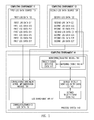
- FIG. 1 is a functional block diagram showing the interaction of various elements for implementing one embodiment of a process for creating enriched log data
- FIG. 2A shows correlated/enriched log data generated by a correlation/enrichment action implementation module, in accordance with one illustrative example of one embodiment
- FIG. 2B shows correlated/enriched log data generated by a correlation/enrichment action implementation module in accordance with one illustrative example of one embodiment
- FIG. 2C shows the insertion of a relevant portion of second log data from a second log data source into the first log data of a first log data source in accordance with one illustrative example of one embodiment
- FIG. 3 is a flow chart depicting a process for creating enriched log data in accordance with one embodiment.
- FIG. 4 is a flow chart depicting a process for creating enriched log data in accordance with one embodiment.
- FIG.s depict one or more exemplary embodiments.
- Embodiments may be implemented in many different forms and should not be construed as limited to the embodiments set forth herein, shown in the FIG.s, and/or described below. Rather, these exemplary embodiments are provided to allow a complete disclosure that conveys the principles of the invention, as set forth in the claims, to those of skill in the art.
- a method and system for creating enriched log data includes a process for creating enriched log data implemented, at least in part, by one or more computing systems.
- the term “computing system”, includes, but is not limited to, a server computing system; a workstation; a desktop computing system; a database system or storage cluster; a switching system; a router; any hardware system; any communications system; any form of proxy system; a gateway system; a firewall system; a load balancing system; or any device, subsystem, or mechanism that includes components that can execute all, or part, of any one of the processes and/or operations as described herein.
- computing system can denote, but is not limited to, systems made up of multiple server computing systems; workstations; desktop computing systems; database systems or storage clusters; switching systems; routers; hardware systems; communications systems; proxy systems; gateway systems; firewall systems; load balancing systems; or any devices that can be used to perform the processes and/or operations as described herein.
- the one or more computing systems implementing the process for creating enriched log data are logically or physically located, and/or associated with, one or more computing environments.
- the term “computing environment” includes, but is not limited to, a logical or physical grouping of connected or networked computing systems using the same infrastructure and systems such as, but not limited to, hardware systems, software systems, and networking/communications systems.
- computing environments are either known environments, e.g., “trusted” environments, or unknown, e.g., “untrusted” environments.
- trusted computing environments are those where the components, infrastructure, communication and networking systems, and security systems associated with the computing systems making up the trusted computing environment, are either under the control of, or known to, a party.
- unknown, or untrusted computing environments are environments and systems where the components, infrastructure, communication and networking systems, and security systems implemented and associated with the computing systems making up the untrusted computing environment, are not under the control of, and/or are not known by, a party, and/or are dynamically configured with new elements capable of being added that are unknown to the party.
- trusted computing environments include the components making up data centers associated with, and/or controlled by, a party, and/or any computing systems, and/or networks of computing systems, associated with, known by, and/or controlled by, a party.
- untrusted computing environments include, but are not limited to, public networks, such as the Internet, various cloud computing environments, and various other forms of distributed computing systems.
- a party desires to transfer data to, and from, a first computing environment that is an untrusted computing environment, such as, but not limited to, a public cloud, a virtual private cloud, and a trusted computing environment, such as, but not limited to, networks of computing systems in a data center controlled by, and/or associated with, the party.
- a party may wish to transfer data between two trusted computing environments, and/or two untrusted computing environments.
- one or more computing systems, and/or one or more computing environments are connected by one or more communications systems, and/or distributed computing system networks, such as, but not limited to: a public cloud; a private cloud; a virtual private cloud (VPN); a subnet; any general network, communications network, or general network/communications network system; a combination of different network types; a public network; a private network; a satellite network; a cable network; or any other network capable of allowing communication between one or more computing systems, as discussed herein, and/or available or known at the time of filing, and/or as developed after the time of filing.
- VPN virtual private cloud
- network includes, but is not limited to, any network or network system such as, but not limited to, a peer-to-peer network, a hybrid peer-to-peer network, a Local Area Network (LAN), a Wide Area Network (WAN), a public network, such as the Internet, a private network, a cellular network, any general network, communications network, or general network/communications network system; a wireless network; a wired network; a wireless and wired combination network; a satellite network; a cable network; any combination of different network types; or any other system capable of allowing communication between one or more computing systems, whether available or known at the time of filing or as later developed.
- a peer-to-peer network such as, but not limited to, a peer-to-peer network, a hybrid peer-to-peer network, a Local Area Network (LAN), a Wide Area Network (WAN), a public network, such as the Internet, a private network, a cellular network, any general network, communications network, or general network/communications network
- FIG. 1 is a functional diagram of the interaction of various elements associated with one embodiment of the method and system for creating enriched log data discussed herein.
- the various elements in FIG. 1 are shown for illustrative purposes as being associated with specific computing environments, such as computing environment 11 , computing environment 12 , and computing environment 14 .
- the exemplary placement of the various elements within these environments and systems in FIG. 1 is made for illustrative purposes only and, in various embodiments, any individual element shown in FIG. 1 , or combination of elements shown in FIG.
- 1 can be implemented and/or deployed on any of one or more computing environments or systems, and/or architectural or infrastructure components, such as one or more hardware systems, one or more software systems, one or more data centers, one or more clouds or cloud types, one or more third party service capabilities, or any other computing environments, architectural, and/or infrastructure components, as discussed herein, and/or as known in the art at the time of filing, and/or as developed/made available after the time of filing.
- architectural or infrastructure components such as one or more hardware systems, one or more software systems, one or more data centers, one or more clouds or cloud types, one or more third party service capabilities, or any other computing environments, architectural, and/or infrastructure components, as discussed herein, and/or as known in the art at the time of filing, and/or as developed/made available after the time of filing.
- the elements shown in FIG. 1 can be under the control of, or otherwise associated with, various parties or entities, or multiple parties or entities, such as, but not limited to, the owner of a data center, a party, and/or entity providing all, or a portion, of a cloud-based computing environment or infrastructure, the owner or provider of a service, the owner or provider of one or more resources accessible via one or more computing environments, and/or any other party, and/or entity providing one or more functions, and/or any other party, and/or entity, as discussed herein, and/or as known in the art at the time of filing, and/or as made known after the time of filing.
- parties or entities such as, but not limited to, the owner of a data center, a party, and/or entity providing all, or a portion, of a cloud-based computing environment or infrastructure, the owner or provider of a service, the owner or provider of one or more resources accessible via one or more computing environments, and/or any other party, and/or entity providing one or more functions, and/or any
- first log data source is a log data source for which it is desired to provide enriched log data correlating, and/or supplementing, the first log data associated with, and generated by, the first log data source.
- the second log data source is a log data source from which it is desired to obtain log enrichment data correlating, and/or supplementing, the first log data associated with, and generated by, the first log data source.
- log data source includes, but is not limited to, any virtual or non-virtual source of log data including, but not limited to, a cloud computing infrastructure, and/or cloud computing infrastructure provider; a service provided through cloud computing environment, and/or a service provider; an application provided through cloud computing environment, and/or an application provider; and/or any virtual or non-virtual asset operating within, or associated with, and or utilized by, one or more resources operating within, or associated with, one or more computing environments, such as a cloud computing environment.
- any virtual or non-virtual source of log data including, but not limited to, a cloud computing infrastructure, and/or cloud computing infrastructure provider; a service provided through cloud computing environment, and/or a service provider; an application provided through cloud computing environment, and/or an application provider; and/or any virtual or non-virtual asset operating within, or associated with, and or utilized by, one or more resources operating within, or associated with, one or more computing environments, such as a cloud computing environment.
- virtual asset includes any virtualized entity or resource, and/or a software subsystem of an actual, or “bare metal” entity.
- virtual assets can be, but are not limited to, virtual machines, virtual servers and instances implemented in a cloud computing environment; administrative and/or data store instances implemented, or associated with, a cloud computing environment; service related instances associated with, and or delivered through, a cloud computing environment; and/or any other virtualized assets and/or sub-systems of “bare metal” physical devices, as discussed herein, and/or as known/available in the art at the time of filing, and/or as developed/made available after the time of filing.
- the log data sources can include, but are not limited to, a virtual machine instance; a virtual server instance; a virtual data store instance; a database or data store; any instance in a cloud computing environment; a cloud computing environment access system; part of a mobile device; part of a remote sensor; part of a laptop computing system; part of a desktop computing system; part of a point-of-sale computing system; and part of an ATM; a server computing system; a workstation; a storage cluster; a switching system; a router; any hardware system; any communications system; any form of proxy system; a gateway system; a firewall system; a load balancing system; a bastion host; an application; an account; an external accessibility monitoring service; an enterprise; a service; a database or data store; a computing environment access system; an external operational monitoring service; a mobile device; a remote sensor; a laptop computing system; a desktop computing system; a point-of-sale computing system; an
- the log data sources are virtual assets instantiated in one or more computing environments using a virtual asset creation system such as a virtual asset creation template through which the creator of the log data source can generate log data source creation data.
- a virtual asset creation system such as a virtual asset creation template through which the creator of the log data source can generate log data source creation data.
- each of the log data sources includes the capability of recording log entry data, also referred to herein as log data entries.
- the log data entries indicate various operations, functions, occurrences, and events related to each individual log data source.
- Specific illustrative examples of log entry data include data indicating one or more of, performance metrics; peer communication and peer communication attempts; user interaction and log data source availability; failed access attempts; successful access attempts; account creation; the setting of security requirements, such as multiple factor authentication requirements; the removal or addition of security requirements; the creation or changing of access control lists; and/or any other activity, function, occurrence, or event, associated with, caused by, or imposed upon, the log data sources.
- the log data entries associated with a given log data source are typically recorded and maintained in isolation from the other log data sources operating within the same computing environment, such as a cloud computing environment, and in many cases those within the same application or service.
- first log data source 110 and second log data source 120 are shown as instantiated and/or deployed in computing environment 11 and computing environment 12 , respectively.
- first log data source 110 is shown as being implemented in computing environment 11 and second log data source 120 is shown as being implemented in computing environment 12 , this placement of first log data source 110 and second log data source 120 is made for illustrative purposes only. Consequently, in various embodiments, first log data source 110 and second log data source 120 can be implemented in the same computing environment, such as, but not limited to, the same cloud computing environment. In other embodiments, first log data source 110 and second log data source 120 can be implemented in different computing environments, including, but not limited to a cloud computing environment and a computing environment outside the cloud computing environment.
- first log data source 110 includes first log data 112 , including first log data entry E 11 , first log data entry E 12 , first log data entry E 13 , first log data entry E 14 , first log data entry E 15 , first log data entry E 16 , and first log data entry E 17 .
- each of the first log data entries E 11 through E 17 represents a log data entry associated with an operation or event directly affecting first log data source 110 .
- second log data source 120 includes second log data 122 , including second log data entry E 21 , second log data entry E 22 , second log data entry E 23 , second log data entry ED, second log data entry E 25 , second log data entry E 26 , and second log data entry E 27 .
- each of the second log data entries E 21 through E 27 represents a log data entry associated with an operation or event directly affecting second log data source 120 .
- first log data 112 is typically a continuous stream of log data entries, as is second log data 122 .
- first log data source 110 and second log data source 120 are shown for simplicity. However, in various embodiments any number of log data sources can be deployed of any number of different types.
- the various log data sources operating within a cloud computing environment, and or associated with a cloud computing environment maintain log data, including log entry data, indicating the occurrence of various events associated with the individual log data sources.
- the various log data sources operate and maintain their respective log entry data in virtual isolation from other log data sources operating within, and/or associated with, the same cloud computing environment.
- this fact contributes to the prior art inability to correlate various events affecting log data sources operating in the same cloud computing environment, or even within the same application or service.
- significant amounts of time and energy are devoted to manually performing forensic analysis to determine that various events occurring within the cloud computing environment, or a common application or service, are connected in a cause-and-effect relationship.
- one or more trigger events are defined.
- the trigger events defined are those events that are likely to have an effect on one or more log data sources, i.e., are likely to have a cause-and-effect relationship with one or more log data sources in a cloud computing environment.
- the trigger events can be from outside an application, relevant to the application, yet independent of the application such as, but not limited to, the deletion of a user account or an “Internet network storm” that could impact the performance.
- a given use case associated with a first log data source is identified, such as a service or application utilizing the log data source.
- the defined use case is used to determine what other log data sources, such as a second log data source, will be used to obtain enrichment, or supplementary, second log data to be correlated, and/or added to, the first log data of the first log data source.
- the identified use case associated with the first log data source is used to determine the trigger events of interest associated with the second log data source, and that would be recorded in the second log data of the second log data source.
- trigger events can be, but are not limited to, one or more of, account creation events; the setting of security requirements, such as multiple factor authentication requirements; the removal or addition of security requirements; the creation or changing of access control lists; the creation and or removal of communications channels; performance metrics analysis or results; peer communications and peer communication attempts; user interaction and log data source availability events; failed access attempts; successful access attempts; the abnormal termination of an application; the increase of error rates in response to customer requests; the detection that an Internet networking event that may impact performance is happening; the alerting by a third party of a denial of service attack; a change in the topology or layout used in the deployment of an application; information, such as a breach into a digital certificate provider, that may alter the security characteristics of an application; and/or any other activity, function, occurrence, or event, associated with, caused by, or imposed upon, one or more log data sources.
- security requirements such as multiple factor authentication requirements
- the removal or addition of security requirements the creation or changing of access control lists
- the creation and or removal of communications channels the creation and or removal
- trigger event log entry data which represents log entry data that would be expected to appear in the second log data generated by the second log data source if the trigger event were to occur.
- data indicating a log entry in the second log data of the second log data source associated with the defined trigger event is defined and recorded.
- defined trigger event data 142 is provided through log enrichment Application Program Interface (API) 141 and defines the trigger events of interest associated with second log data source 120 . As also seen in FIG. 1 , defined trigger event data 142 is used to generate defined trigger event log entry data ED 143 .
- API Application Program Interface
- log enrichment API is provided as part of a process system 140 which also includes monitoring/analysis module 144 and correlated/enriched log data 151 generated, in one embodiment, by correlation/enrichment action implementation module 150 of log enrichment API 141 .
- process system 140 is implemented in computing environment 14 that, in this specific illustrative example, is a third computing environment distinct from both computing environment 11 and computing environment 12 .
- this particular implementation scheme is shown for illustrative purposes only and, in other embodiments, first log data source 110 , second log data source 120 , and process system 140 can all, or in any combination, be implemented in the same computing environment.
- the second log data generated by the second log data source is monitored, e.g., read or scanned, to identify a log data entry in the second log data of the second log data source matching the defined trigger event log data entry data.
- one or more correlation and or supplementation/enrichment actions are taken to indicate, and/or add data indicating, a connection between the detected matching log data entry in the second log data and the first log data of the first log data source.
- monitoring/analysis module 144 of process system 140 is used to monitor second log data 122 and read/scan each of second log data entries E 21 through E 27 , including second log data entry ED.
- defined trigger event log entry data ED 143 is provided to monitoring/analysis module 144 .
- each of the second log data entries E 21 through E 27 , and defined trigger event log entry data ED 143 are provided as input data to matching engine 145 of monitoring/analysis module 144 to identify any of second log data entries E 21 through E 27 that match defined trigger event log entry data ED 143 .
- monitoring/analysis module 144 detects a match between second log data entry ED of second log data 122 and defined trigger event log entry data ED 143 .
- trigger event detected data 147 is generated and provided to correlation/enrichment action implementation module 150 .
- the correlation and/or supplementation/enrichment action taken includes inserting linking data into the first log data stream of the first log data source indicating that the first log data should be read with, or in light of, the detected trigger event log entry data of the second log data from the second log data source, and/or a portion of, or the entirety of, the second log data from the second log data source.
- first log data from the first log data source and the second log data from the second log data source are connected so that the first log data from the first log data source can be interpreted using at least the part of the second log data from the second log data source indicating the defined trigger event took place.
- the linking data is inserted into the first log data from the first log data source manually, e.g., via a human interface and human interaction; or semi-automatically, e.g., subject to review and/or approval; or automatically, e.g., without subsequent review or approval.
- the correlation and/or supplementation/enrichment action taken includes generating correlated/enriched log data in a separate log data stream including the detected trigger event log entry data of the second log data from the second log data source, and/or a portion of, or the entirety of, the second log data from the second log data source.
- the first log data from the first log data source and the correlated/enriched log data in the separate log data stream, including the detected trigger event log entry data of the second log data from the second log data source are connected so that the first log data from the first log data source can be interpreted using at least the part of the second log data from the second log data source indicating the defined trigger event took place.
- the correlated/enriched log data is generated in the separate log data stream manually, e.g., via a human interface and human interaction; or semi-automatically, e.g., subject to review and/or approval; or automatically, e.g., without subsequent review or approval.
- the correlation and/or supplementation/enrichment action taken includes inserting at least a relevant portion of the second log data of the second log data source directly into the first log data of the first log data source.
- the relevant portion of the second log data inserted into the first log data includes, but is not limited to, the log data entry in the second log data of the second log data source matching the defined trigger event log data entry data.
- the first log data from the first log data source is directly supplemented and enriched using the relevant portion of the second log data from the second log data source indicating that the defined trigger event has occurred. Consequently, any review of the first log data from the first log data source directly indicates the occurrence of the defined trigger event so that the original log data entries in the first log data can be interpreted in light of the occurrence of the defined trigger event.
- the insertion of the relevant portion of the second log data from the second log data source into the first log data of the first log data source is accomplished using a log enrichment API through which a user, such as an application or service provider, can specifically request insertion of relevant second log data.
- the relevant portion of the second log data from the second log data source is inserted into the first log data of the first log data source manually, e.g., via human interaction with the log enrichment API; or semi-automatically, e.g., subject to review and/or approval through the log enrichment API; or automatically, e.g., based on instructions provided through the log enrichment API, but without subsequent review or approval.
- correlation/enrichment action implementation module 150 is shown as part of log enrichment API 141 of process system 140 . As discussed above, in various embodiments, correlation/enrichment action implementation module 150 receives trigger event detected data 147 and then accesses second log data 120 of second log data source 120 , and/or first log data 112 of first log data source 110 , and uses the accessed data to generate correlated/enriched log data 151 .
- log data from two or more log data sources can be effectively and efficiently correlated, and or supplemented, to connect events, and the consequences of those events, on multiple components, assets, and/or resources implemented in different portions of a given computing environment, such as a cloud computing environment, and/or in different computing environments. Consequently, using one or more of the methods and systems for creating enriched log data discussed herein, cause-and-effect relationships within one or more computing environments are automatically identified without the need to devote significant time and resources.
- portions of one or more of the processes, sub-processes, steps, operations and/or instructions can be re-grouped as portions of one or more other of processes, sub-processes, steps, operations and/or instructions discussed herein. Consequently, the particular order and/or grouping of the processes, sub-processes, steps, operations and/or instructions discussed herein do not limit the scope of the invention as claimed below.
- a process for creating enriched log data includes obtaining access to first log data from a first log data source. In one embodiment, access to second log data from a second log data source is also obtained. In one embodiment, the second log data source is distinct from the first log data source such that the second log data is external log data with respect to the first log data.
- a trigger event is defined and trigger event log entry data indicating the trigger event has occurred is defined.
- the second log data from the second log data source is monitored to detect the defined trigger event log entry data in the second log data from the second log data source.
- the detected trigger event log entry data in the second log data from the second log data source is correlated with the first log data from the first log data source.
- FIG. 3 is a flow chart of a process 300 for creating enriched log data in accordance with one embodiment.
- process 300 for creating enriched log data begins at ENTER OPERATION 301 of FIG. 3 and process flow proceeds to OBTAIN ACCESS TO FIRST LOG DATA FROM A FIRST LOG DATA SOURCE OPERATION 303 .
- At OBTAIN ACCESS TO FIRST LOG DATA FROM A FIRST LOG DATA SOURCE OPERATION 303 access to first log data from a first log data source is obtained.
- the first log data source of OBTAIN ACCESS TO FIRST LOG DATA FROM A FIRST LOG DATA SOURCE OPERATION 303 is a log data source for which it is desired to provide enriched log data correlating, and/or supplementing, the first log data associated with, and generated by, the first log data source.
- first log data sources there can be multiple first log data sources, i.e., log data sources for which it is desired to provide enriched log data at OBTAIN ACCESS TO FIRST LOG DATA FROM A FIRST LOG DATA SOURCE OPERATION 303 .
- process flow proceeds to OBTAIN ACCESS TO SECOND LOG DATA FROM A SECOND LOG DATA SOURCE OPERATION 305 .
- the second log data source of OBTAIN ACCESS TO SECOND LOG DATA FROM A SECOND LOG DATA SOURCE OPERATION 305 is a log data source from which it is desired to obtain log enrichment data correlating, and/or supplementing, the first log data associated with, and generated by, the first log data source of OBTAIN ACCESS TO FIRST LOG DATA FROM A FIRST LOG DATA SOURCE OPERATION 303 .
- the term “log data source” as used in connection with OBTAIN ACCESS TO FIRST LOG DATA FROM A FIRST LOG DATA SOURCE OPERATION 303 and OBTAIN ACCESS TO SECOND LOG DATA FROM A SECOND LOG DATA SOURCE OPERATION 305 includes, but is not limited to, any virtual or non-virtual source of log data including, but not limited to, a cloud computing infrastructure, and/or cloud computing infrastructure provider; a service provided through cloud computing environment, and/or a service provider; an application provided through cloud computing environment, and/or an application provider; and/or any virtual or non-virtual asset operating within, or associated with, and or utilized by, one or more resources operating within, or associated with, one or more computing environments, such as a cloud computing environment.
- virtual asset includes any virtualized entity or resource, and/or a software subsystem of an actual, or “bare metal” entity.
- virtual assets can be, but are not limited to, virtual machines, virtual servers and instances implemented in a cloud computing environment; administrative and/or data store instances implemented, or associated with, a cloud computing environment; service related instances associated with, and or delivered through, a cloud computing environment; and/or any other virtualized assets and/or sub-systems of “bare metal” physical devices, as discussed herein, and/or as known/available in the art at the time of filing, and/or as developed/made available after the time of filing.
- the log data sources can include, but are not limited to, a virtual machine instance; a virtual server instance; a virtual data store instance; a database or data store; any instance in a cloud computing environment; a cloud computing environment access system; part of a mobile device; part of a remote sensor; part of a laptop computing system; part of a desktop computing system; part of a point-of-sale computing system; and part of an ATM; a server computing system; a workstation; a storage cluster; a switching system; a router; any hardware system; any communications system; any form of proxy system; a gateway system; a firewall system; a load balancing system; a bastion host; an application; an account; an external accessibility monitoring service; an enterprise; a service; a database or data store; a computing environment access system; an external operational monitoring service; a mobile device; a remote sensor; a laptop computing system; a desktop computing system; a point-of-sale computing system; an
- the log data sources are virtual assets instantiated in one or more computing environments using a virtual asset creation system such as a virtual asset creation template through which the creator of the log data source can generate log data source creation data.
- a virtual asset creation system such as a virtual asset creation template through which the creator of the log data source can generate log data source creation data.
- each of the log data sources of OBTAIN ACCESS TO FIRST LOG DATA FROM A FIRST LOG DATA SOURCE OPERATION 303 and OBTAIN ACCESS TO SECOND LOG DATA FROM A SECOND LOG DATA SOURCE OPERATION 305 includes the capability of recording log entry data, also referred to herein as log data entries.
- the log data entries indicate various operations, functions, occurrences, and events related to each individual log data source.
- log entry data include data indicating one or more of, performance metrics; peer communication and peer communication attempts; user interaction and log data source availability; failed access attempts; successful access attempts; account creation; the setting of security requirements, such as multiple factor authentication requirements; the removal or addition of security requirements; the creation or changing of access control lists; and/or any other activity, function, occurrence, or event, associated with, caused by, or imposed upon, the log data sources.
- security requirements such as multiple factor authentication requirements
- the removal or addition of security requirements the creation or changing of access control lists
- any other activity, function, occurrence, or event associated with, caused by, or imposed upon, the log data sources.
- the log data entries associated with a given log data source are typically recorded and maintained in isolation from the other log data sources operating within the same computing environment, such as a cloud computing environment, and in many cases those within the same application or service.
- process flow proceeds to DEFINE TRIGGER EVENT LOG ENTRY DATA OPERATION 307 .
- the various log data sources operating within a cloud computing environment, and or associated with a cloud computing environment, of OBTAIN ACCESS TO FIRST LOG DATA FROM A FIRST LOG DATA SOURCE OPERATION 303 and OBTAIN ACCESS TO SECOND LOG DATA FROM A SECOND LOG DATA SOURCE OPERATION 305 maintain log data including log entry data indicating the occurrence of various events associated with the individual log data sources.
- OBTAIN ACCESS TO FIRST LOG DATA FROM A FIRST LOG DATA SOURCE OPERATION 303 and OBTAIN ACCESS TO SECOND LOG DATA FROM A SECOND LOG DATA SOURCE OPERATION 305 operate and maintain their respective log entry data in virtual isolation from other log data sources operating within, and/or associated with, the same cloud computing environment.
- this fact contributes to the prior art inability to correlate various events affecting log data sources operating in the same cloud computing environment, or even those within the same application or service.
- significant amounts of time and energy are devoted to manually performing forensic analysis to determine that various events occurring within the cloud computing environment, or a common application or service, are connected in a cause-and-effect relationship.
- the trigger events defined at DEFINE TRIGGER EVENT LOG ENTRY DATA OPERATION 307 are those events that are likely to have an effect on one or more log data sources of OBTAIN ACCESS TO FIRST LOG DATA FROM A FIRST LOG DATA SOURCE OPERATION 303 , i.e., are likely to have a cause-and-effect relationship with one or more log data sources of OBTAIN ACCESS TO FIRST LOG DATA FROM A FIRST LOG DATA SOURCE OPERATION 303 in a cloud computing environment.
- the trigger events can be from outside an application, relevant to the application, yet independent of the application such as, but not limited to, the deletion of a user account or an “Internet network storm” that could impact the performance.
- a given use case associated with a first log data source of OBTAIN ACCESS TO FIRST LOG DATA FROM A FIRST LOG DATA SOURCE OPERATION 303 is identified, such as a service or application utilizing the log data source.
- the defined use case is used at DEFINE TRIGGER EVENT LOG ENTRY DATA OPERATION 307 to determine what other log data sources, such as a second log data source of OBTAIN ACCESS TO SECOND LOG DATA FROM A SECOND LOG DATA SOURCE OPERATION 305 , will be used to obtain enrichment, or supplementary, second log data to be correlated, and/or added to, the first log data of the first log data source of OBTAIN ACCESS TO FIRST LOG DATA FROM A FIRST LOG DATA SOURCE OPERATION 303 .
- a second log data source of OBTAIN ACCESS TO SECOND LOG DATA FROM A SECOND LOG DATA SOURCE OPERATION 305 will be used to obtain enrichment, or supplementary, second log data to be correlated, and/or added to, the first log data of the first log data source of OBTAIN ACCESS TO FIRST LOG DATA FROM A FIRST LOG DATA SOURCE OPERATION 303 .
- the identified use case associated with the first log data source is used to determine the trigger events of interest associated with the second log data source, and that would be recorded in the second log data of the second log data source of OBTAIN ACCESS TO SECOND LOG DATA FROM A SECOND LOG DATA SOURCE OPERATION 305 .
- trigger events of DEFINE TRIGGER EVENT LOG ENTRY DATA OPERATION 307 can be, but are not limited to, one or more of, account creation events; the setting of security requirements, such as multiple factor authentication requirements; the removal or addition of security requirements; the creation or changing of access control lists; the creation and or removal of communications channels; performance metrics analysis or results; peer communications and peer communication attempts; user interaction and log data source availability events; failed access attempts; successful access attempts; the abnormal termination of an application; the increase of error rates in response to customer requests; the detection that an Internet networking event that may impact performance is happening; the alerting by a third party of a denial of service attack; a change in the topology or layout used in the deployment of an application; information, such as a breach into a digital certificate provider, that may alter the security characteristics of an application; and/or any other activity, function, occurrence, or event, associated with, caused by, or imposed upon, one or more log data sources.
- security requirements such as multiple factor authentication requirements
- the removal or addition of security requirements the
- trigger event log entry data is defined at DEFINE TRIGGER EVENT LOG ENTRY DATA OPERATION 307 which represents log entry data that would be expected to appear in the second log data generated by the second log data source of OBTAIN ACCESS TO SECOND LOG DATA FROM A SECOND LOG DATA SOURCE OPERATION 305 if the trigger event of DEFINE TRIGGER EVENT LOG ENTRY DATA OPERATION 307 were to occur.
- data indicating a log entry in the second log data of the second log data source associated with the defined trigger event is defined and recorded at DEFINE TRIGGER EVENT LOG ENTRY DATA OPERATION 307 .
- process flow proceeds to MONITOR THE SECOND LOG DATA FROM THE SECOND LOG DATA SOURCE OPERATION 309 .
- the second log data generated by the second log data source of OBTAIN ACCESS TO SECOND LOG DATA FROM A SECOND LOG DATA SOURCE OPERATION 305 is monitored, e.g., read or scanned, at MONITOR THE SECOND LOG DATA FROM THE SECOND LOG DATA SOURCE OPERATION 309 to identify a log data entry in the second log data of the second log data source of OBTAIN ACCESS TO SECOND LOG DATA FROM A SECOND LOG DATA SOURCE OPERATION 305 matching the defined trigger event log data entry data of DEFINE TRIGGER EVENT LOG ENTRY DATA OPERATION 307 .
- a log data entry in the second log data of the second log data source of OBTAIN ACCESS TO SECOND LOG DATA FROM A SECOND LOG DATA SOURCE OPERATION 305 matching the defined trigger event log data entry data of DEFINE TRIGGER EVENT LOG ENTRY DATA OPERATION 307 is detected.
- one or more correlation actions are taken to indicate a connection between the detected matching log data entry of DETECT THE TRIGGER EVENT LOG ENTRY DATA IN THE SECOND LOG DATA FROM THE SECOND LOG DATA SOURCE OPERATION 311 in the second log data of OBTAIN ACCESS TO SECOND LOG DATA FROM A SECOND LOG DATA SOURCE OPERATION 305 and the first log data of the first log data source of OBTAIN ACCESS TO FIRST LOG DATA FROM A FIRST LOG DATA SOURCE OPERATION 303 .
- the correlation action taken at CORRELATE THE DETECTED TRIGGER EVENT LOG ENTRY DATA IN THE SECOND LOG DATA FROM THE SECOND LOG DATA SOURCE WITH THE FIRST LOG DATA FROM THE FIRST LOG DATA SOURCE OPERATION 313 includes inserting linking data into the first log data stream of the first log data source of OBTAIN ACCESS TO FIRST LOG DATA FROM A FIRST LOG DATA SOURCE OPERATION 303 indicating that the first log data should be read with, or in light of, the detected trigger event log entry data of the second log data from the second log data source of DETECT THE TRIGGER EVENT LOG ENTRY DATA IN THE SECOND LOG DATA
- first log data from the first log data source and the second log data from the second log data source are connected so that the first log data from the first log data source can be interpreted using at least the part of the second log data from the second log data source indicating the defined trigger event of DEFINE TRIGGER EVENT LOG ENTRY DATA OPERATION 307 took place.
- FIG. 2A shows correlated/enriched log data 151 A, such as a specific example of correlated/enriched log data 151 of FIG. 1 , generated by a correlation/enrichment action implementation module, such as correlation/enrichment action implementation module 150 of FIG. 1 , in accordance with one illustrative example of one embodiment.
- first log data source 110 includes first log data 112 , including first log data entry E 11 , first log data entry E 12 , first log data entry E 13 , first log data entry E 14 , first log data entry E 15 , first log data entry E 16 , and first log data entry E 17 .
- each of the first log data entries E 11 through E 17 represents a log data entry associated with an operation or event directly affecting first log data source 110 .
- second log data source 120 includes second log data 122 , including second log data entry E 21 , second log data entry E 22 , second log data entry E 23 , second log data entry ED, second log data entry E 25 , second log data entry E 26 , and second log data entry E 27 .
- each of the second log data entries E 21 through E 27 represents a log data entry associated with an operation or event directly affecting second log data source 120 .
- linking data 201 is inserted into first log data 112 of the first log data source 110 of OBTAIN ACCESS TO FIRST LOG DATA FROM A FIRST LOG DATA SOURCE OPERATION 303 indicating that first log data 112 should be read with, or in light of, the detected trigger event log entry data, i.e., second log data ED, of second log data 122 from second log data source 120 of DETECT THE TRIGGER EVENT LOG ENTRY DATA IN THE SECOND LOG DATA FROM THE SECOND LOG DATA SOURCE OPERATION 311 , and/or
- the linking data is inserted into the first log data from the first log data source manually, e.g., via a human interface and human interaction; or semi-automatically, e.g., subject to review and/or approval; or automatically, e.g., without subsequent review or approval.
- the correlation action taken at CORRELATE THE DETECTED TRIGGER EVENT LOG ENTRY DATA IN THE SECOND LOG DATA FROM THE SECOND LOG DATA SOURCE WITH THE FIRST LOG DATA FROM THE FIRST LOG DATA SOURCE OPERATION 313 includes generating correlated/enriched log data in a separate log data stream including the detected trigger event log entry data of DETECT THE TRIGGER EVENT LOG ENTRY DATA IN THE SECOND LOG DATA FROM THE SECOND LOG DATA SOURCE OPERATION 311 from the second log data of MONITOR THE SECOND LOG DATA FROM THE SECOND LOG DATA SOURCE OPERATION 309 , and/
- the first log data from the first log data source of OBTAIN ACCESS TO FIRST LOG DATA FROM A FIRST LOG DATA SOURCE OPERATION 303 and the correlated/enriched log data in the separate log data stream, including the detected trigger event log entry data of the second log data from the second log data source, are connected so that the first log data from the first log data source of OBTAIN ACCESS TO FIRST LOG DATA FROM A FIRST LOG DATA SOURCE OPERATION 303 can be interpreted using at least the part of the second log data from the second log data source of OBTAIN ACCESS TO SECOND LOG DATA FROM A SECOND LOG DATA SOURCE OPERATION 305 indicating the defined trigger event of DEFINE TRIGGER EVENT LOG ENTRY DATA OPERATION 307 took place.
- FIG. 2B shows correlated/enriched log data 151 B, such as a specific example of correlated/enriched log data 151 of FIG. 1 , generated by a correlation/enrichment action implementation module, such as correlation/enrichment action implementation module 150 of FIG. 1 , in accordance with one illustrative example of one embodiment.
- first log data source 110 includes first log data 112 , including first log data entry E 11 , first log data entry E 12 , first log data entry E 13 , first log data entry E 14 , first log data entry E 15 , first log data entry E 16 , and first log data entry E 17 .
- each of the first log data entries E 11 through E 17 represents a log data entry associated with an operation or event directly affecting first log data source 110 .
- second log data source 120 includes second log data 122 , including second log data entry E 21 , second log data entry E 22 , second log data entry E 23 , second log data entry ED, second log data entry E 25 , second log data entry E 26 , and second log data entry E 27 .
- each of the second log data entries E 21 through E 27 represents a log data entry associated with an operation or event directly affecting second log data source 120 .
- linking data 201 and second log data ED are included in a third log data stream of correlated/enriched log data 151 B so that first log data 112 can be read with, or in light of, the detected trigger event log entry data, i.e., second log data ED, of second log data 122 from second log data source 120 of DETECT THE TRIGGER EVENT LOG ENTRY DATA IN THE SECOND LOG DATA FROM THE SECOND LOG DATA SOURCE OPERATION 311 , and/or a portion of, or the entirety of, second log data 122 from second log data source 120 of
- the correlated/enriched log data is generated in the separate log data stream manually, e.g., via a human interface and human interaction; or semi-automatically, e.g., subject to review and/or approval; or automatically, e.g., without subsequent review or approval.
- a service provided through a cloud computing environment employs multiple virtual machine instances and the virtual machine instances are accessed via the Internet using variable sets of IP addresses assigned to the service by a cloud computing environment provider hosting the service.
- each of the virtual machine instances is a first log data source and would typically maintain its own internal first log data recording various log entries related to the events associated with that virtual machine instance, i.e., each virtual machine instance would be a first source of log data associated with that virtual machine instance.
- the cloud computing environment provider would also maintain log data recording events associated with the cloud infrastructure, i.e., the cloud computing environment provider would be a second log data source maintaining second log data associated with the cloud infrastructure.
- the second log entry data associated with the cloud infrastructure would include log entry data indicating the event of the one or more IP addresses being cancelled.
- the first log data for each of the virtual machine instances using the cancelled IP addresses would undoubtedly also include log entry data indicating that these resources dropped offline once the IP addresses were destroyed.
- the first log data for each of the virtual machine instances would not be correlated with the second log data associated with the cloud infrastructure. Consequently, considerable time and energy could be expended to “discover” that the IP addresses associated with the virtual machine instances we destroyed at the infrastructure level and that this event was the cause of these virtual machine instances dropping offline.
- the second log entry data associated with the cloud infrastructure indicating the destruction of the IP addresses is correlated with the first log entry data from the virtual machine instances indicating the instances dropped offline. Consequently, using process 300 for creating enriched log data it is immediately apparent why the virtual machine instances dropped offline.
- process 300 for creating enriched log data is exited to await new data.
- log data from two or more log data sources can be effectively and efficiently correlated to connect events, and the consequences of those events, on multiple components, assets, and/or resources implemented in different portions of a given computing environment, such as a cloud computing environment, and/or in different computing environments. Consequently, using process 300 for creating enriched log data, cause-and-effect relationships within one or more computing environments are automatically identified without the need to devote significant time and resources.
- a process for creating enriched log data includes obtaining access to first log data from a first log data source. In one embodiment, access to second log data from a second log data source is also obtained. In one embodiment, the second log data source is distinct from the first log data source such that the second log data is external log data with respect to the first log data.
- a trigger event is defined and trigger event log entry data indicating the trigger event has occurred is defined.
- the second log data from the second log data source is monitored to detect the defined trigger event log entry data in the second log data from the second log data source.
- the defined trigger event log entry data in the second log data from the second log data source is detected, at least part of the second log data from the second log data source is inserted into the first log data of the first log data source.
- FIG. 4 is a flow chart of a process 400 for creating enriched log data in accordance with one embodiment.
- process 400 for creating enriched log data begins at ENTER OPERATION 401 of FIG. 4 and process flow proceeds to OBTAIN ACCESS TO FIRST LOG DATA FROM A FIRST LOG DATA SOURCE OPERATION 403 .
- At OBTAIN ACCESS TO FIRST LOG DATA FROM A FIRST LOG DATA SOURCE OPERATION 403 access to first log data from a first log data source is obtained.
- the first log data source of OBTAIN ACCESS TO FIRST LOG DATA FROM A FIRST LOG DATA SOURCE OPERATION 403 is a log data source for which it is desired to provide enriched log data correlating, and/or supplementing, the first log data associated with, and generated by, the first log data source.
- first log data sources there can be multiple first log data sources, i.e., log data sources for which it is desired to provide enriched log data at OBTAIN ACCESS TO FIRST LOG DATA FROM A FIRST LOG DATA SOURCE OPERATION 403 .
- process flow proceeds to OBTAIN ACCESS TO SECOND LOG DATA FROM A SECOND LOG DATA SOURCE OPERATION 405 .
- the second log data source of OBTAIN ACCESS TO SECOND LOG DATA FROM A SECOND LOG DATA SOURCE OPERATION 405 is a log data source from which it is desired to obtain log enrichment data correlating, and/or supplementing, the first log data associated with, and generated by, the first log data source of OBTAIN ACCESS TO FIRST LOG DATA FROM A FIRST LOG DATA SOURCE OPERATION 403 .
- the term “log data source” as used in connection with OBTAIN ACCESS TO FIRST LOG DATA FROM A FIRST LOG DATA SOURCE OPERATION 403 and OBTAIN ACCESS TO SECOND LOG DATA FROM A SECOND LOG DATA SOURCE OPERATION 405 includes, but is not limited to, any virtual or non-virtual source of log data including, but not limited to, a cloud computing infrastructure, and/or cloud computing infrastructure provider; a service provided through cloud computing environment, and/or a service provider; an application provided through cloud computing environment, and/or an application provider; and/or any virtual or non-virtual asset operating within, or associated with, and or utilized by, one or more resources operating within, or associated with, one or more computing environments, such as a cloud computing environment.
- virtual asset includes any virtualized entity or resource, and/or a software subsystem of an actual, or “bare metal” entity.
- virtual assets can be, but are not limited to, virtual machines, virtual servers and instances implemented in a cloud computing environment; administrative and/or data store instances implemented, or associated with, a cloud computing environment; service related instances associated with, and or delivered through, a cloud computing environment; and/or any other virtualized assets and/or sub-systems of “bare metal” physical devices, as discussed herein, and/or as known/available in the art at the time of filing, and/or as developed/made available after the time of filing.
- the log data sources can include, but are not limited to, a virtual machine instance; a virtual server instance; a virtual data store instance; a database or data store; any instance in a cloud computing environment; a cloud computing environment access system; part of a mobile device; part of a remote sensor; part of a laptop computing system; part of a desktop computing system; part of a point-of-sale computing system; and part of an ATM; a server computing system; a workstation; a storage cluster; a switching system; a router; any hardware system; any communications system; any form of proxy system; a gateway system; a firewall system; a load balancing system; a bastion host; an application; an account; an external accessibility monitoring service; an enterprise; a service; a database or data store; a computing environment access system; an external operational monitoring service; a mobile device; a remote sensor; a laptop computing system; a desktop computing system; a point-of-sale computing system; an
- the log data sources are virtual assets instantiated in one or more computing environments using a virtual asset creation system such as a virtual asset creation template through which the creator of the log data source can generate log data source creation data.
- a virtual asset creation system such as a virtual asset creation template through which the creator of the log data source can generate log data source creation data.
- each of the log data sources of OBTAIN ACCESS TO FIRST LOG DATA FROM A FIRST LOG DATA SOURCE OPERATION 403 and OBTAIN ACCESS TO SECOND LOG DATA FROM A SECOND LOG DATA SOURCE OPERATION 405 includes the capability of recording log entry data, also referred to herein as log data entries.
- the log data entries indicate various operations, functions, occurrences, and events related to each individual log data source.
- log entry data include data indicating one or more of, performance metrics; peer communication and peer communication attempts; user interaction and log data source availability; failed access attempts; successful access attempts; account creation; the setting of security requirements, such as multiple factor authentication requirements; the removal or addition of security requirements; the creation or changing of access control lists; and/or any other activity, function, occurrence, or event, associated with, caused by, or imposed upon, the log data sources.
- security requirements such as multiple factor authentication requirements
- the removal or addition of security requirements the creation or changing of access control lists
- any other activity, function, occurrence, or event associated with, caused by, or imposed upon, the log data sources.
- the log data entries associated with a given log data source are typically recorded and maintained in isolation from the other log data sources operating within the same computing environment, such as a cloud computing environment, and in many cases those within the same application or service.
- process flow proceeds to DEFINE TRIGGER EVENT LOG ENTRY DATA OPERATION 407 .
- the various log data sources operating within a cloud computing environment, and or associated with a cloud computing environment, of OBTAIN ACCESS TO FIRST LOG DATA FROM A FIRST LOG DATA SOURCE OPERATION 403 and OBTAIN ACCESS TO SECOND LOG DATA FROM A SECOND LOG DATA SOURCE OPERATION 405 maintain log data including log entry data indicating the occurrence of various events associated with the individual log data sources.
- OBTAIN ACCESS TO FIRST LOG DATA FROM A FIRST LOG DATA SOURCE OPERATION 403 and OBTAIN ACCESS TO SECOND LOG DATA FROM A SECOND LOG DATA SOURCE OPERATION 405 operate and maintain their respective log entry data in virtual isolation from other log data sources operating within, and/or associated with, the same cloud computing environment.
- this fact contributes to the prior art inability to correlate various events affecting log data sources operating in the same cloud computing environment, or even those within the same application or service.
- significant amounts of time and energy are devoted to manually performing forensic analysis to determine that various events occurring within the cloud computing environment, or a common application or service, are connected in a cause-and-effect relationship.
- the trigger events defined at DEFINE TRIGGER EVENT LOG ENTRY DATA OPERATION 407 are those events that are likely to have an effect on one or more log data sources of OBTAIN ACCESS TO FIRST LOG DATA FROM A FIRST LOG DATA SOURCE OPERATION 403 , i.e., are likely to have a cause-and-effect relationship with one or more log data sources of OBTAIN ACCESS TO FIRST LOG DATA FROM A FIRST LOG DATA SOURCE OPERATION 403 in a cloud computing environment.
- the trigger events can be from outside an application, relevant to the application, yet independent of the application such as, but not limited to, the deletion of a user account or an “Internet network storm” that could impact the performance.
- a given use case associated with a first log data source of OBTAIN ACCESS TO FIRST LOG DATA FROM A FIRST LOG DATA SOURCE OPERATION 403 is identified, such as a service or application utilizing the log data source.
- the defined use case is used at DEFINE TRIGGER EVENT LOG ENTRY DATA OPERATION 407 to determine what other log data sources, such as a second log data source of OBTAIN ACCESS TO SECOND LOG DATA FROM A SECOND LOG DATA SOURCE OPERATION 405 , will be used to obtain enrichment, or supplementary, second log data to be correlated, and/or added to, the first log data of the first log data source of OBTAIN ACCESS TO FIRST LOG DATA FROM A FIRST LOG DATA SOURCE OPERATION 403 .
- a second log data source of OBTAIN ACCESS TO SECOND LOG DATA FROM A SECOND LOG DATA SOURCE OPERATION 405 will be used to obtain enrichment, or supplementary, second log data to be correlated, and/or added to, the first log data of the first log data source of OBTAIN ACCESS TO FIRST LOG DATA FROM A FIRST LOG DATA SOURCE OPERATION 403 .
- the identified use case associated with the first log data source is used to determine the trigger events of interest associated with the second log data source, and that would be recorded in the second log data of the second log data source of OBTAIN ACCESS TO SECOND LOG DATA FROM A SECOND LOG DATA SOURCE OPERATION 405 .
- trigger events of DEFINE TRIGGER EVENT LOG ENTRY DATA OPERATION 407 can be, but are not limited to, one or more of, account creation events; the setting of security requirements, such as multiple factor authentication requirements; the removal or addition of security requirements; the creation or changing of access control lists; the creation and or removal of communications channels; performance metrics analysis or results; peer communications and peer communication attempts; user interaction and log data source availability events; failed access attempts; successful access attempts; the abnormal termination of an application; the increase of error rates in response to customer requests; the detection that an Internet networking event that may impact performance is happening; the alerting by a third party of a denial of service attack; a change in the topology or layout used in the deployment of an application; information, such as a breach into a digital certificate provider, that may alter the security characteristics of an application; and/or any other activity, function, occurrence, or event, associated with, caused by, or imposed upon, one or more log data sources.
- security requirements such as multiple factor authentication requirements
- the removal or addition of security requirements the
- trigger event log entry data is defined at DEFINE TRIGGER EVENT LOG ENTRY DATA OPERATION 407 which represents log entry data that would be expected to appear in the second log data generated by the second log data source of OBTAIN ACCESS TO SECOND LOG DATA FROM A SECOND LOG DATA SOURCE OPERATION 405 if the trigger event of DEFINE TRIGGER EVENT LOG ENTRY DATA OPERATION 407 were to occur.
- data indicating a log entry in the second log data of the second log data source associated with the defined trigger event is defined and recorded at DEFINE TRIGGER EVENT LOG ENTRY DATA OPERATION 407 .
- process flow proceeds to MONITOR THE SECOND LOG DATA FROM THE SECOND LOG DATA SOURCE OPERATION 409 .
- the second log data generated by the second log data source of OBTAIN ACCESS TO SECOND LOG DATA FROM A SECOND LOG DATA SOURCE OPERATION 405 is monitored, e.g., read or scanned, at MONITOR THE SECOND LOG DATA FROM THE SECOND LOG DATA SOURCE OPERATION 409 to identify a log data entry in the second log data of the second log data source of OBTAIN ACCESS TO SECOND LOG DATA FROM A SECOND LOG DATA SOURCE OPERATION 405 matching the defined trigger event log data entry data of DEFINE TRIGGER EVENT LOG ENTRY DATA OPERATION 407 .
- a log data entry in the second log data of the second log data source of OBTAIN ACCESS TO SECOND LOG DATA FROM A SECOND LOG DATA SOURCE OPERATION 405 matching the defined trigger event log data entry data of DEFINE TRIGGER EVENT LOG ENTRY DATA OPERATION 407 is detected.
- one or more supplementation/enrichment actions are taken to add data indicating a connection between the detected matching log data entry in the second log data and the first log data of the first log data source.
- the supplementation/enrichment action taken at INSERT AT LEAST PART OF THE SECOND LOG DATA FROM THE SECOND LOG DATA SOURCE INTO THE FIRST LOG DATA OF THE FIRST LOG DATA SOURCE OPERATION 413 to add data indicating a connection between the detected matching log data entry in the second log data and the first log data of the first log data source includes inserting at least a relevant portion of the second log data of the second log data source of OBTAIN ACCESS TO SECOND LOG DATA FROM A SECOND LOG DATA SOURCE OPERATION 405 directly into the first log data of the first log data source of OBTAIN ACCESS TO FIRST LOG DATA FROM A FIRST LOG DATA SOURCE OPERATION 403 .
- the relevant portion of the second log data inserted into the first log data at INSERT AT LEAST PART OF THE SECOND LOG DATA FROM THE SECOND LOG DATA SOURCE INTO THE FIRST LOG DATA OF THE FIRST LOG DATA SOURCE OPERATION 413 includes, but is not limited to, the log data entry in the second log data of the second log data source matching the defined trigger event log data entry data of DETECT THE TRIGGER EVENT LOG ENTRY DATA IN THE SECOND LOG DATA FROM THE SECOND LOG DATA SOURCE OPERATION 411 .
- any review of the first log data from the first log data source directly indicates the occurrence of the defined trigger event so that the original log data entries in the first log data can be interpreted in light of the occurrence of the defined trigger event.
- the insertion of the relevant portion of the second log data from the second log data source into the first log data of the first log data source is accomplished at INSERT AT LEAST PART OF THE SECOND LOG DATA FROM THE SECOND LOG DATA SOURCE INTO THE FIRST LOG DATA OF THE FIRST LOG DATA SOURCE OPERATION 413 using a log enrichment API through which a user, such as an application or service provider, can specifically request insertion of relevant second log data.
- FIG. 2C shows, the insertion of the relevant portion of second log data 122 , i.e., second log data ED, from second log data source 120 into the first log data 112 of first log data source 110 in accordance with one illustrative example of one embodiment.
- first log data source 110 includes first log data 112 , including first log data entry E 11 , first log data entry E 12 , first log data entry E 13 , first log data entry E 14 , first log data entry E 15 , first log data entry E 16 , and first log data entry E 17 .
- each of the first log data entries E 11 through E 17 represents a log data entry associated with an operation or event directly affecting first log data source 110 .
- second log data source 120 includes second log data 122 , including second log data entry E 21 , second log data entry E 22 , second log data entry E 23 , second log data entry ED, second log data entry E 25 , second log data entry E 26 , and second log data entry E 27 .
- each of the second log data entries E 21 through E 27 represents a log data entry associated with an operation or event directly affecting second log data source 120 .
- correlation/enrichment action implementation module 150 in response to a detected log data entry, i.e., second log data ED, in second log data 122 of the second log data source 120 that matches the defined trigger event log data entry data, at DETECT THE TRIGGER EVENT LOG ENTRY DATA IN THE SECOND LOG DATA FROM THE SECOND LOG DATA SOURCE OPERATION 411 , correlation/enrichment action implementation module 150 generates log data ED insertion request 203 .
- second log data ED is inserted into first log data 112 of the first log data source 110 of OBTAIN ACCESS TO FIRST LOG DATA FROM A FIRST LOG DATA SOURCE OPERATION 403 so that first log data 112 is read with, and in light of, the detected trigger event log entry data, i.e., second log data ED, of second log data 122 from second log data source 120 of DETECT THE TRIGGER EVENT LOG ENTRY DATA IN THE SECOND LOG DATA FROM THE SECOND LOG DATA SOURCE OPERATION 411 , and/or a portion of, or the entirety of, second log data 122 from second log data source 120 of OBTAIN ACCESS TO SECOND LOG DATA FROM A SECOND LOG DATA SOURCE OPERATION 405 .
- the relevant portion of the second log data from the second log data source is inserted into the first log data of the first log data source manually, e.g., via human interaction with the log enrichment API; or semi-automatically, e.g., subject to review and/or approval through the log enrichment API; or automatically, e.g., based on instructions provided through the log enrichment API, but without subsequent review or approval.
- a service provided through a cloud computing environment employs multiple virtual machine instances and the virtual machine instances are accessed via the Internet using variable sets of IP addresses assigned to the service by a cloud computing environment provider hosting the service.
- each of the virtual machine instances is a first log data source and would typically maintain its own internal first log data recording various log entries related to the events associated with that virtual machine instance, i.e., each virtual machine instance would be a first source of log data associated with that virtual machine instance.
- the cloud computing environment provider would also maintain log data recording events associated with the cloud infrastructure, i.e., the cloud computing environment provider would be a second log data source maintaining second log data associated with the cloud infrastructure.
- the second log entry data associated with the cloud infrastructure would include log entry data indicating the event of the one or more IP addresses being cancelled.
- the first log data for each of the virtual machine instances using the cancelled IP addresses would undoubtedly also include log entry data indicating that these resources dropped offline once the IP addresses were destroyed.
- the first log data for each of the virtual machine instances would not be correlated with the second log data associated with the cloud infrastructure. Consequently, considerable time and energy could be expended to “discover” that the IP addresses associated with the virtual machine instances we destroyed at the infrastructure level and that this event was the cause of these virtual machine instances dropping offline.
- the second log entry data associated with the cloud infrastructure indicating the destruction of the IP addresses is inserted into and included with the first log entry data from the virtual machine instances indicating the instances dropped offline. Consequently, using process 400 for creating enriched log data it is immediately apparent why the virtual machine instances dropped offline.
- process 400 for creating enriched log data is exited to await new data.
- log data from two or more log data sources can be effectively and efficiently supplemented to connect events, and the consequences of those events, on multiple components, assets, and/or resources implemented in different portions of a given computing environment, such as a cloud computing environment, and/or in different computing environments. Consequently, using process 400 for creating enriched log data, cause-and-effect relationships within one or more computing environments are automatically identified without the need to devote significant time and resources.
- certain aspects of one embodiment include process steps and/or operations and/or instructions described herein for illustrative purposes in a particular order and/or grouping.
- the particular order and/or grouping shown and discussed herein are illustrative only and not limiting.
- Those of skill in the art will recognize that other orders and/or grouping of the process steps and/or operations and/or instructions are possible and, in some embodiments, one or more of the process steps and/or operations and/or instructions discussed above can be combined and/or deleted.
- portions of one or more of the process steps and/or operations and/or instructions can be re-grouped as portions of one or more other of the process steps and/or operations and/or instructions discussed herein. Consequently, the particular order and/or grouping of the process steps and/or operations and/or instructions discussed herein do not limit the scope of the invention as claimed below.
- the present invention also relates to an apparatus or system for performing the operations described herein.
- This apparatus or system may be specifically constructed for the required purposes, or the apparatus or system can comprise a general purpose system selectively activated or configured/reconfigured by a computer program stored on a computer program product as discussed herein that can be accessed by a computing system or other device.
- the present invention is well suited to a wide variety of computer network systems operating over numerous topologies.
- the configuration and management of large networks comprise storage devices and computers that are communicatively coupled to similar or dissimilar computers and storage devices over a private network, a LAN, a WAN, a private network, or a public network, such as the Internet.
Abstract
Access to first log data from a first log data source and second log data from a second log data source is obtained. Trigger event log data is defined and the second log data from the second log data source is monitored to detect the defined trigger event log data in the second log data. If the defined trigger event log data is detected in the second log data from the second log data source, the detected trigger event log data in the second log data from the second log data source is correlated with the first log data from the first log data source, and/or at least part of the second log data from the second log data source is inserted into the first log data from the first log data source.
Description
Distributed computing systems, such as cloud computing environments, typically consist of a multitude of resources, many of which operate in relative isolation. In addition, many of these resources are themselves comprised of multiple sub-components. For instance, a given cloud computing environment often hosts multiple applications and services, each of which often utilizes multiple virtual and non-virtual assets such as server instances, data storage instances, as well as non-virtual resources, such as third party access systems, and various “bare metal” resources.
A long standing problem associated with the diversity of components and elements operating in a given cloud computing environment has been the inability to accurately and efficiently identify and correlate related events taking place in different portions of the cloud. One reason correlating events in the cloud has proven so difficult is the fact that many of the resources hosted in a given cloud computing environment maintain their own log data in relative isolation. Consequently, while it might be easily understood why a given asset in a cloud computing environment experienced a given event if it were known that a related trigger event had taken place in another portion of the cloud, without this correlation of log data entries from two different log data sources, there is often no explanation for the occurrence of an event, or the behavior of a given asset, in the cloud computing environment.
As an illustrative example, assume a service provided through a cloud computing environment employs multiple virtual machine instances and the virtual machine instances are accessed via the Internet using variable sets of IP addresses assigned to the service by a cloud computing environment provider hosting the service. In this case, each of the virtual machine instances would typically maintain its own internal log data recording various log entries related to the events associated with that virtual machine instance, i.e., each virtual machine instance would be a source of log data associated with that virtual machine instance. In addition, in this specific illustrative example, the cloud computing environment provider would also maintain log data recording events associated with the cloud infrastructure, i.e., the cloud computing environment provider would be a source of log data entries associated with the cloud infrastructure. In addition, the service would typically maintain its own log data, often consisting of the collection of log data from each of the associated virtual machine instances.
For the purposes of illustration, assume one or more of the IP addresses assigned to the service by the cloud computing environment provider are cancelled/destroyed by the cloud computing environment provider. In this case, log entry data associated with the cloud infrastructure would indicate the event of the one or more IP addresses being cancelled. In addition, the log data for each of the virtual machine instances using the cancelled IP addresses would undoubtedly also include log entry data indicating the events of these resources dropping offline.
Using current systems, the log data for each of the virtual machine instances would not be correlated with the log data associated with the cloud infrastructure. Consequently, considerable time and energy could be expended to “discover” that the IP addresses associated with the virtual machine instances we destroyed at the infrastructure level and that this event was the cause of these virtual machine instances dropping offline. However, if the log entry data associated with the cloud infrastructure indicating the destruction of the IP addresses were correlated with the log entry data from the virtual machine instances indicating the instances dropped offline, it would be immediately apparent why the virtual machine instances dropped offline.
What is needed is a method and system for correlating, and/or supplementing, log entry data from two different log data sources in a cloud environment when one or more trigger events connecting the log entry data from the two different log data sources is detected.
In accordance with one embodiment, a method and system for creating enriched log data includes obtaining access to first log data from a first log data source. In one embodiment, access to second log data from a second log data source is also obtained. In one embodiment, the second log data source is distinct from the first log data source such that the second log data is external log data with respect to the first log data.
In one embodiment, a trigger event is defined and trigger event log entry data indicating the trigger event has occurred is defined. In one embodiment, the second log data from the second log data source is monitored to detect the defined trigger event log entry data in the second log data from the second log data source. In one embodiment, if the defined trigger event log entry data in the second log data from the second log data source is detected, the detected trigger event log entry data in the second log data from the second log data source is correlated with the first log data from the first log data source.
In accordance with one embodiment, a method and system for creating enriched log data includes obtaining access to first log data from a first log data source. In one embodiment, access to second log data from a second log data source is also obtained. In one embodiment, the second log data source is distinct from the first log data source such that the second log data is external log data with respect to the first log data.
In one embodiment, a trigger event is defined and trigger event log entry data indicating the trigger event has occurred is defined. In one embodiment, the second log data from the second log data source is monitored to detect the defined trigger event log entry data in the second log data from the second log data source. In one embodiment, if the defined trigger event log entry data in the second log data from the second log data source is detected, at least part of the second log data from the second log data source is inserted into the first log data of the first log data source.
Common reference numerals are used throughout the FIG.s and the detailed description to indicate like elements. One skilled in the art will readily recognize that the above FIG.s are examples and that other architectures, modes of operation, orders of operation and elements/functions can be provided and implemented without departing from the characteristics and features of the invention, as set forth in the claims.
Embodiments will now be discussed with reference to the accompanying FIG.s, which depict one or more exemplary embodiments. Embodiments may be implemented in many different forms and should not be construed as limited to the embodiments set forth herein, shown in the FIG.s, and/or described below. Rather, these exemplary embodiments are provided to allow a complete disclosure that conveys the principles of the invention, as set forth in the claims, to those of skill in the art.
In accordance with one embodiment, a method and system for creating enriched log data includes a process for creating enriched log data implemented, at least in part, by one or more computing systems.
As used herein, the term “computing system”, includes, but is not limited to, a server computing system; a workstation; a desktop computing system; a database system or storage cluster; a switching system; a router; any hardware system; any communications system; any form of proxy system; a gateway system; a firewall system; a load balancing system; or any device, subsystem, or mechanism that includes components that can execute all, or part, of any one of the processes and/or operations as described herein.
In addition, as used herein, the term computing system, can denote, but is not limited to, systems made up of multiple server computing systems; workstations; desktop computing systems; database systems or storage clusters; switching systems; routers; hardware systems; communications systems; proxy systems; gateway systems; firewall systems; load balancing systems; or any devices that can be used to perform the processes and/or operations as described herein.
In various embodiments, the one or more computing systems implementing the process for creating enriched log data are logically or physically located, and/or associated with, one or more computing environments. As used herein, the term “computing environment” includes, but is not limited to, a logical or physical grouping of connected or networked computing systems using the same infrastructure and systems such as, but not limited to, hardware systems, software systems, and networking/communications systems. Typically, computing environments are either known environments, e.g., “trusted” environments, or unknown, e.g., “untrusted” environments. Typically, trusted computing environments are those where the components, infrastructure, communication and networking systems, and security systems associated with the computing systems making up the trusted computing environment, are either under the control of, or known to, a party. In contrast, unknown, or untrusted computing environments are environments and systems where the components, infrastructure, communication and networking systems, and security systems implemented and associated with the computing systems making up the untrusted computing environment, are not under the control of, and/or are not known by, a party, and/or are dynamically configured with new elements capable of being added that are unknown to the party.
Examples of trusted computing environments include the components making up data centers associated with, and/or controlled by, a party, and/or any computing systems, and/or networks of computing systems, associated with, known by, and/or controlled by, a party. Examples of untrusted computing environments include, but are not limited to, public networks, such as the Internet, various cloud computing environments, and various other forms of distributed computing systems.
It is often the case that a party desires to transfer data to, and from, a first computing environment that is an untrusted computing environment, such as, but not limited to, a public cloud, a virtual private cloud, and a trusted computing environment, such as, but not limited to, networks of computing systems in a data center controlled by, and/or associated with, the party. However, in other situations, a party may wish to transfer data between two trusted computing environments, and/or two untrusted computing environments.
In one embodiment, one or more computing systems, and/or one or more computing environments, are connected by one or more communications systems, and/or distributed computing system networks, such as, but not limited to: a public cloud; a private cloud; a virtual private cloud (VPN); a subnet; any general network, communications network, or general network/communications network system; a combination of different network types; a public network; a private network; a satellite network; a cable network; or any other network capable of allowing communication between one or more computing systems, as discussed herein, and/or available or known at the time of filing, and/or as developed after the time of filing.
As used herein, the term “network” includes, but is not limited to, any network or network system such as, but not limited to, a peer-to-peer network, a hybrid peer-to-peer network, a Local Area Network (LAN), a Wide Area Network (WAN), a public network, such as the Internet, a private network, a cellular network, any general network, communications network, or general network/communications network system; a wireless network; a wired network; a wireless and wired combination network; a satellite network; a cable network; any combination of different network types; or any other system capable of allowing communication between one or more computing systems, whether available or known at the time of filing or as later developed.
In addition, the elements shown in FIG. 1 , and/or the computing environments, systems and architectural and/or infrastructure components, deploying the elements shown in FIG. 1 , can be under the control of, or otherwise associated with, various parties or entities, or multiple parties or entities, such as, but not limited to, the owner of a data center, a party, and/or entity providing all, or a portion, of a cloud-based computing environment or infrastructure, the owner or provider of a service, the owner or provider of one or more resources accessible via one or more computing environments, and/or any other party, and/or entity providing one or more functions, and/or any other party, and/or entity, as discussed herein, and/or as known in the art at the time of filing, and/or as made known after the time of filing.
In accordance with one embodiment, access to first log data from a first log data source is obtained. In various embodiments, the first log data source is a log data source for which it is desired to provide enriched log data correlating, and/or supplementing, the first log data associated with, and generated by, the first log data source. In various embodiments, there can be multiple first log data sources, i.e., log data sources for which it is desired to provide enriched log data.
In accordance with one embodiment, access to second log data from a second log data source is obtained. In accordance with one embodiment, and as discussed below, the second log data source is a log data source from which it is desired to obtain log enrichment data correlating, and/or supplementing, the first log data associated with, and generated by, the first log data source. In various embodiments, there can be multiple second log data sources, i.e. log data sources from which it is desired to obtain log enrichment data.
In one embodiment, the term “log data source” includes, but is not limited to, any virtual or non-virtual source of log data including, but not limited to, a cloud computing infrastructure, and/or cloud computing infrastructure provider; a service provided through cloud computing environment, and/or a service provider; an application provided through cloud computing environment, and/or an application provider; and/or any virtual or non-virtual asset operating within, or associated with, and or utilized by, one or more resources operating within, or associated with, one or more computing environments, such as a cloud computing environment.
As used herein, the term “virtual asset” includes any virtualized entity or resource, and/or a software subsystem of an actual, or “bare metal” entity. In various embodiments, virtual assets can be, but are not limited to, virtual machines, virtual servers and instances implemented in a cloud computing environment; administrative and/or data store instances implemented, or associated with, a cloud computing environment; service related instances associated with, and or delivered through, a cloud computing environment; and/or any other virtualized assets and/or sub-systems of “bare metal” physical devices, as discussed herein, and/or as known/available in the art at the time of filing, and/or as developed/made available after the time of filing.
As an even more specific example, in various embodiments, the log data sources can include, but are not limited to, a virtual machine instance; a virtual server instance; a virtual data store instance; a database or data store; any instance in a cloud computing environment; a cloud computing environment access system; part of a mobile device; part of a remote sensor; part of a laptop computing system; part of a desktop computing system; part of a point-of-sale computing system; and part of an ATM; a server computing system; a workstation; a storage cluster; a switching system; a router; any hardware system; any communications system; any form of proxy system; a gateway system; a firewall system; a load balancing system; a bastion host; an application; an account; an external accessibility monitoring service; an enterprise; a service; a database or data store; a computing environment access system; an external operational monitoring service; a mobile device; a remote sensor; a laptop computing system; a desktop computing system; a point-of-sale computing system; an ATM; or any other virtual or non-virtual asset as discussed herein, and/or as known in the art at the time of filing, and/or as becomes known after the time of filing.
In one embodiment, the log data sources are virtual assets instantiated in one or more computing environments using a virtual asset creation system such as a virtual asset creation template through which the creator of the log data source can generate log data source creation data.
In various embodiments, each of the log data sources includes the capability of recording log entry data, also referred to herein as log data entries. In various embodiments, the log data entries indicate various operations, functions, occurrences, and events related to each individual log data source. Specific illustrative examples of log entry data include data indicating one or more of, performance metrics; peer communication and peer communication attempts; user interaction and log data source availability; failed access attempts; successful access attempts; account creation; the setting of security requirements, such as multiple factor authentication requirements; the removal or addition of security requirements; the creation or changing of access control lists; and/or any other activity, function, occurrence, or event, associated with, caused by, or imposed upon, the log data sources. As noted above, currently, the log data entries associated with a given log data source are typically recorded and maintained in isolation from the other log data sources operating within the same computing environment, such as a cloud computing environment, and in many cases those within the same application or service.
Referring to FIG. 1 , first log data source 110 and second log data source 120 are shown as instantiated and/or deployed in computing environment 11 and computing environment 12, respectively.
As discussed above, despite the fact that, in this specific illustrative example of FIG. 1 , first log data source 110 is shown as being implemented in computing environment 11 and second log data source 120 is shown as being implemented in computing environment 12, this placement of first log data source 110 and second log data source 120 is made for illustrative purposes only. Consequently, in various embodiments, first log data source 110 and second log data source 120 can be implemented in the same computing environment, such as, but not limited to, the same cloud computing environment. In other embodiments, first log data source 110 and second log data source 120 can be implemented in different computing environments, including, but not limited to a cloud computing environment and a computing environment outside the cloud computing environment.
As also seen in FIG. 1 , first log data source 110 includes first log data 112, including first log data entry E11, first log data entry E12, first log data entry E13, first log data entry E14, first log data entry E15, first log data entry E16, and first log data entry E17. In various embodiments, each of the first log data entries E11 through E17 represents a log data entry associated with an operation or event directly affecting first log data source 110.
Likewise, as also seen in FIG. 1 , second log data source 120 includes second log data 122, including second log data entry E21, second log data entry E22, second log data entry E23, second log data entry ED, second log data entry E25, second log data entry E26, and second log data entry E27. In various embodiments, each of the second log data entries E21 through E27 represents a log data entry associated with an operation or event directly affecting second log data source 120.
While only seven log data entries are shown in FIG. 1 for both first log data source 110 and second log data source 120, those of skill in the art will readily recognize that, in various embodiments, any number of log data entries can be part of first log data 112 and second log data 122. In addition, those of skill in the art will readily recognize that the number of log data entries in first log data 112 will typically not be equal to the number of log data entries in second log data 122. Indeed, those of skill in the art will readily recognize that, in an actual implementation, first log data 112 is typically a continuous stream of log data entries, as is second log data 122.
In addition, in the illustrative example of FIG. 1 , only two log data sources, i.e., first log data source 110 and second log data source 120, are shown for simplicity. However, in various embodiments any number of log data sources can be deployed of any number of different types.
As noted above, currently, the various log data sources operating within a cloud computing environment, and or associated with a cloud computing environment, maintain log data, including log entry data, indicating the occurrence of various events associated with the individual log data sources. As also noted above, currently, the various log data sources operate and maintain their respective log entry data in virtual isolation from other log data sources operating within, and/or associated with, the same cloud computing environment. As also noted above, this fact contributes to the prior art inability to correlate various events affecting log data sources operating in the same cloud computing environment, or even within the same application or service. As a result, currently, significant amounts of time and energy are devoted to manually performing forensic analysis to determine that various events occurring within the cloud computing environment, or a common application or service, are connected in a cause-and-effect relationship. In short, currently, there is no effective and efficient mechanism for correlating log entry data of two or more log data sources that are, in fact, connected by a common event.
To address this issue, in one embodiment, one or more trigger events are defined. In various embodiments, the trigger events defined are those events that are likely to have an effect on one or more log data sources, i.e., are likely to have a cause-and-effect relationship with one or more log data sources in a cloud computing environment. In various embodiments, the trigger events can be from outside an application, relevant to the application, yet independent of the application such as, but not limited to, the deletion of a user account or an “Internet network storm” that could impact the performance.
In various embodiments, a given use case associated with a first log data source is identified, such as a service or application utilizing the log data source. In one embodiment, the defined use case is used to determine what other log data sources, such as a second log data source, will be used to obtain enrichment, or supplementary, second log data to be correlated, and/or added to, the first log data of the first log data source. In addition, the identified use case associated with the first log data source is used to determine the trigger events of interest associated with the second log data source, and that would be recorded in the second log data of the second log data source.
As specific illustrative examples, in various embodiments, trigger events can be, but are not limited to, one or more of, account creation events; the setting of security requirements, such as multiple factor authentication requirements; the removal or addition of security requirements; the creation or changing of access control lists; the creation and or removal of communications channels; performance metrics analysis or results; peer communications and peer communication attempts; user interaction and log data source availability events; failed access attempts; successful access attempts; the abnormal termination of an application; the increase of error rates in response to customer requests; the detection that an Internet networking event that may impact performance is happening; the alerting by a third party of a denial of service attack; a change in the topology or layout used in the deployment of an application; information, such as a breach into a digital certificate provider, that may alter the security characteristics of an application; and/or any other activity, function, occurrence, or event, associated with, caused by, or imposed upon, one or more log data sources.
In one embodiment, once the trigger events of interest are defined, trigger event log entry data is defined which represents log entry data that would be expected to appear in the second log data generated by the second log data source if the trigger event were to occur. In short, data indicating a log entry in the second log data of the second log data source associated with the defined trigger event is defined and recorded.
Returning to FIG. 1 , defined trigger event data 142 is provided through log enrichment Application Program Interface (API) 141 and defines the trigger events of interest associated with second log data source 120. As also seen in FIG. 1 , defined trigger event data 142 is used to generate defined trigger event log entry data ED 143.
As seen in FIG. 1 , log enrichment API is provided as part of a process system 140 which also includes monitoring/analysis module 144 and correlated/enriched log data 151 generated, in one embodiment, by correlation/enrichment action implementation module 150 of log enrichment API 141.
As also seen in FIG. 1 , in this specific illustrative example, process system 140 is implemented in computing environment 14 that, in this specific illustrative example, is a third computing environment distinct from both computing environment 11 and computing environment 12. As noted above, this particular implementation scheme is shown for illustrative purposes only and, in other embodiments, first log data source 110, second log data source 120, and process system 140 can all, or in any combination, be implemented in the same computing environment.
In one embodiment, once the defined trigger event log entry data associated with the defined trigger event is defined, the second log data generated by the second log data source is monitored, e.g., read or scanned, to identify a log data entry in the second log data of the second log data source matching the defined trigger event log data entry data.
In one embodiment, if a log data entry in the second log data of the second log data source matching the defined trigger event log data entry data is detected, one or more correlation and or supplementation/enrichment actions are taken to indicate, and/or add data indicating, a connection between the detected matching log data entry in the second log data and the first log data of the first log data source.
Returning to FIG. 1 , monitoring/analysis module 144 of process system 140 is used to monitor second log data 122 and read/scan each of second log data entries E21 through E27, including second log data entry ED. As also seen in FIG. 1 , defined trigger event log entry data ED 143 is provided to monitoring/analysis module 144. As seen in FIG. 1 , each of the second log data entries E21 through E27, and defined trigger event log entry data ED 143, are provided as input data to matching engine 145 of monitoring/analysis module 144 to identify any of second log data entries E21 through E27 that match defined trigger event log entry data ED 143.
As seen in FIG. 1 , in this specific illustrative example, using matching engine 145, monitoring/analysis module 144 detects a match between second log data entry ED of second log data 122 and defined trigger event log entry data ED 143. As a result, trigger event detected data 147 is generated and provided to correlation/enrichment action implementation module 150.
In one embodiment, if a log data entry in the second log data of the second log data source matching the defined trigger event log data entry data is detected, the correlation and/or supplementation/enrichment action taken includes inserting linking data into the first log data stream of the first log data source indicating that the first log data should be read with, or in light of, the detected trigger event log entry data of the second log data from the second log data source, and/or a portion of, or the entirety of, the second log data from the second log data source.
In this way, the first log data from the first log data source and the second log data from the second log data source are connected so that the first log data from the first log data source can be interpreted using at least the part of the second log data from the second log data source indicating the defined trigger event took place.
In various embodiments, the linking data is inserted into the first log data from the first log data source manually, e.g., via a human interface and human interaction; or semi-automatically, e.g., subject to review and/or approval; or automatically, e.g., without subsequent review or approval.
In one embodiment, if a log data entry in the second log data of the second log data source matching the defined trigger event log data entry data is detected, the correlation and/or supplementation/enrichment action taken includes generating correlated/enriched log data in a separate log data stream including the detected trigger event log entry data of the second log data from the second log data source, and/or a portion of, or the entirety of, the second log data from the second log data source.
In this embodiment, the first log data from the first log data source and the correlated/enriched log data in the separate log data stream, including the detected trigger event log entry data of the second log data from the second log data source, are connected so that the first log data from the first log data source can be interpreted using at least the part of the second log data from the second log data source indicating the defined trigger event took place.
In various embodiments, the correlated/enriched log data is generated in the separate log data stream manually, e.g., via a human interface and human interaction; or semi-automatically, e.g., subject to review and/or approval; or automatically, e.g., without subsequent review or approval.
In one embodiment, if a log data entry in the second log data of the second log data source matching the defined trigger event log data entry data is detected, the correlation and/or supplementation/enrichment action taken includes inserting at least a relevant portion of the second log data of the second log data source directly into the first log data of the first log data source. In one embodiment, the relevant portion of the second log data inserted into the first log data includes, but is not limited to, the log data entry in the second log data of the second log data source matching the defined trigger event log data entry data.
In this embodiment, the first log data from the first log data source is directly supplemented and enriched using the relevant portion of the second log data from the second log data source indicating that the defined trigger event has occurred. Consequently, any review of the first log data from the first log data source directly indicates the occurrence of the defined trigger event so that the original log data entries in the first log data can be interpreted in light of the occurrence of the defined trigger event.
As noted above, in various embodiments, the insertion of the relevant portion of the second log data from the second log data source into the first log data of the first log data source is accomplished using a log enrichment API through which a user, such as an application or service provider, can specifically request insertion of relevant second log data.
In various embodiments, the relevant portion of the second log data from the second log data source is inserted into the first log data of the first log data source manually, e.g., via human interaction with the log enrichment API; or semi-automatically, e.g., subject to review and/or approval through the log enrichment API; or automatically, e.g., based on instructions provided through the log enrichment API, but without subsequent review or approval.
Returning to FIG. 1 , correlation/enrichment action implementation module 150 is shown as part of log enrichment API 141 of process system 140. As discussed above, in various embodiments, correlation/enrichment action implementation module 150 receives trigger event detected data 147 and then accesses second log data 120 of second log data source 120, and/or first log data 112 of first log data source 110, and uses the accessed data to generate correlated/enriched log data 151.
Using one or more of the methods and systems for creating enriched log data discussed herein, log data from two or more log data sources can be effectively and efficiently correlated, and or supplemented, to connect events, and the consequences of those events, on multiple components, assets, and/or resources implemented in different portions of a given computing environment, such as a cloud computing environment, and/or in different computing environments. Consequently, using one or more of the methods and systems for creating enriched log data discussed herein, cause-and-effect relationships within one or more computing environments are automatically identified without the need to devote significant time and resources.
In the discussion above, certain aspects of one embodiment include processes, sub-processes, steps, operations and/or instructions described herein for illustrative purposes in a particular order and/or grouping. However, the particular order and/or grouping shown and discussed herein are illustrative only and not limiting. Those of skill in the art will recognize that other orders and/or grouping of the processes, sub-processes, steps, operations and/or instructions are possible and, in some embodiments, one or more of the processes, sub-processes, steps, operations and/or instructions discussed above can be combined and/or deleted. In addition, portions of one or more of the processes, sub-processes, steps, operations and/or instructions can be re-grouped as portions of one or more other of processes, sub-processes, steps, operations and/or instructions discussed herein. Consequently, the particular order and/or grouping of the processes, sub-processes, steps, operations and/or instructions discussed herein do not limit the scope of the invention as claimed below.
Process
In accordance with one embodiment, a process for creating enriched log data includes obtaining access to first log data from a first log data source. In one embodiment, access to second log data from a second log data source is also obtained. In one embodiment, the second log data source is distinct from the first log data source such that the second log data is external log data with respect to the first log data.
In one embodiment, a trigger event is defined and trigger event log entry data indicating the trigger event has occurred is defined. In one embodiment, the second log data from the second log data source is monitored to detect the defined trigger event log entry data in the second log data from the second log data source. In one embodiment, if the defined trigger event log entry data in the second log data from the second log data source is detected, the detected trigger event log entry data in the second log data from the second log data source is correlated with the first log data from the first log data source.
In one embodiment, at OBTAIN ACCESS TO FIRST LOG DATA FROM A FIRST LOG DATA SOURCE OPERATION 303 access to first log data from a first log data source is obtained.
In various embodiments, the first log data source of OBTAIN ACCESS TO FIRST LOG DATA FROM A FIRST LOG DATA SOURCE OPERATION 303 is a log data source for which it is desired to provide enriched log data correlating, and/or supplementing, the first log data associated with, and generated by, the first log data source.
In various embodiments, there can be multiple first log data sources, i.e., log data sources for which it is desired to provide enriched log data at OBTAIN ACCESS TO FIRST LOG DATA FROM A FIRST LOG DATA SOURCE OPERATION 303.
In one embodiment, once access to first log data from a first log data source is obtained at OBTAIN ACCESS TO FIRST LOG DATA FROM A FIRST LOG DATA SOURCE OPERATION 303, process flow proceeds to OBTAIN ACCESS TO SECOND LOG DATA FROM A SECOND LOG DATA SOURCE OPERATION 305.
In one embodiment, at OBTAIN ACCESS TO SECOND LOG DATA FROM A SECOND LOG DATA SOURCE OPERATION 305 access to second log data from a second log data source is obtained.
In accordance with one embodiment, and as discussed below, the second log data source of OBTAIN ACCESS TO SECOND LOG DATA FROM A SECOND LOG DATA SOURCE OPERATION 305 is a log data source from which it is desired to obtain log enrichment data correlating, and/or supplementing, the first log data associated with, and generated by, the first log data source of OBTAIN ACCESS TO FIRST LOG DATA FROM A FIRST LOG DATA SOURCE OPERATION 303. In various embodiments, there can be multiple second log data sources, i.e. log data sources from which it is desired to obtain log enrichment data at OBTAIN ACCESS TO SECOND LOG DATA FROM A SECOND LOG DATA SOURCE OPERATION 305.
In one embodiment, the term “log data source” as used in connection with OBTAIN ACCESS TO FIRST LOG DATA FROM A FIRST LOG DATA SOURCE OPERATION 303 and OBTAIN ACCESS TO SECOND LOG DATA FROM A SECOND LOG DATA SOURCE OPERATION 305 includes, but is not limited to, any virtual or non-virtual source of log data including, but not limited to, a cloud computing infrastructure, and/or cloud computing infrastructure provider; a service provided through cloud computing environment, and/or a service provider; an application provided through cloud computing environment, and/or an application provider; and/or any virtual or non-virtual asset operating within, or associated with, and or utilized by, one or more resources operating within, or associated with, one or more computing environments, such as a cloud computing environment.
As used herein, the term “virtual asset” includes any virtualized entity or resource, and/or a software subsystem of an actual, or “bare metal” entity. In various embodiments, virtual assets can be, but are not limited to, virtual machines, virtual servers and instances implemented in a cloud computing environment; administrative and/or data store instances implemented, or associated with, a cloud computing environment; service related instances associated with, and or delivered through, a cloud computing environment; and/or any other virtualized assets and/or sub-systems of “bare metal” physical devices, as discussed herein, and/or as known/available in the art at the time of filing, and/or as developed/made available after the time of filing.
As an even more specific example, in various embodiments, the log data sources can include, but are not limited to, a virtual machine instance; a virtual server instance; a virtual data store instance; a database or data store; any instance in a cloud computing environment; a cloud computing environment access system; part of a mobile device; part of a remote sensor; part of a laptop computing system; part of a desktop computing system; part of a point-of-sale computing system; and part of an ATM; a server computing system; a workstation; a storage cluster; a switching system; a router; any hardware system; any communications system; any form of proxy system; a gateway system; a firewall system; a load balancing system; a bastion host; an application; an account; an external accessibility monitoring service; an enterprise; a service; a database or data store; a computing environment access system; an external operational monitoring service; a mobile device; a remote sensor; a laptop computing system; a desktop computing system; a point-of-sale computing system; an ATM; or any other virtual or non-virtual asset as discussed herein, and/or as known in the art at the time of filing, and/or as becomes known after the time of filing.
In one embodiment, the log data sources are virtual assets instantiated in one or more computing environments using a virtual asset creation system such as a virtual asset creation template through which the creator of the log data source can generate log data source creation data.
In various embodiments, each of the log data sources of OBTAIN ACCESS TO FIRST LOG DATA FROM A FIRST LOG DATA SOURCE OPERATION 303 and OBTAIN ACCESS TO SECOND LOG DATA FROM A SECOND LOG DATA SOURCE OPERATION 305 includes the capability of recording log entry data, also referred to herein as log data entries. In various embodiments, the log data entries indicate various operations, functions, occurrences, and events related to each individual log data source. Specific illustrative examples of log entry data include data indicating one or more of, performance metrics; peer communication and peer communication attempts; user interaction and log data source availability; failed access attempts; successful access attempts; account creation; the setting of security requirements, such as multiple factor authentication requirements; the removal or addition of security requirements; the creation or changing of access control lists; and/or any other activity, function, occurrence, or event, associated with, caused by, or imposed upon, the log data sources. As noted above, currently, the log data entries associated with a given log data source are typically recorded and maintained in isolation from the other log data sources operating within the same computing environment, such as a cloud computing environment, and in many cases those within the same application or service.
In one embodiment, once access to second log data from a second log data source is obtained at OBTAIN ACCESS TO SECOND LOG DATA FROM A SECOND LOG DATA SOURCE OPERATION 305, process flow proceeds to DEFINE TRIGGER EVENT LOG ENTRY DATA OPERATION 307.
As noted above, currently, the various log data sources operating within a cloud computing environment, and or associated with a cloud computing environment, of OBTAIN ACCESS TO FIRST LOG DATA FROM A FIRST LOG DATA SOURCE OPERATION 303 and OBTAIN ACCESS TO SECOND LOG DATA FROM A SECOND LOG DATA SOURCE OPERATION 305 maintain log data including log entry data indicating the occurrence of various events associated with the individual log data sources.
As also noted above, currently, the various log data sources of OBTAIN ACCESS TO FIRST LOG DATA FROM A FIRST LOG DATA SOURCE OPERATION 303 and OBTAIN ACCESS TO SECOND LOG DATA FROM A SECOND LOG DATA SOURCE OPERATION 305 operate and maintain their respective log entry data in virtual isolation from other log data sources operating within, and/or associated with, the same cloud computing environment.
As also noted above, this fact contributes to the prior art inability to correlate various events affecting log data sources operating in the same cloud computing environment, or even those within the same application or service. As a result, currently, significant amounts of time and energy are devoted to manually performing forensic analysis to determine that various events occurring within the cloud computing environment, or a common application or service, are connected in a cause-and-effect relationship. In short, currently, there is no effective and efficient mechanism for correlating log entry data of two or more log data sources that are, in fact, connected by a common event.
To address this issue, in one embodiment, at DEFINE TRIGGER EVENT LOG ENTRY DATA OPERATION 307 one or more trigger events are defined. In various embodiments, the trigger events defined at DEFINE TRIGGER EVENT LOG ENTRY DATA OPERATION 307 are those events that are likely to have an effect on one or more log data sources of OBTAIN ACCESS TO FIRST LOG DATA FROM A FIRST LOG DATA SOURCE OPERATION 303, i.e., are likely to have a cause-and-effect relationship with one or more log data sources of OBTAIN ACCESS TO FIRST LOG DATA FROM A FIRST LOG DATA SOURCE OPERATION 303 in a cloud computing environment. In various embodiments, the trigger events can be from outside an application, relevant to the application, yet independent of the application such as, but not limited to, the deletion of a user account or an “Internet network storm” that could impact the performance.
In various embodiments, at DEFINE TRIGGER EVENT LOG ENTRY DATA OPERATION 307 a given use case associated with a first log data source of OBTAIN ACCESS TO FIRST LOG DATA FROM A FIRST LOG DATA SOURCE OPERATION 303 is identified, such as a service or application utilizing the log data source.
In one embodiment, the defined use case is used at DEFINE TRIGGER EVENT LOG ENTRY DATA OPERATION 307 to determine what other log data sources, such as a second log data source of OBTAIN ACCESS TO SECOND LOG DATA FROM A SECOND LOG DATA SOURCE OPERATION 305, will be used to obtain enrichment, or supplementary, second log data to be correlated, and/or added to, the first log data of the first log data source of OBTAIN ACCESS TO FIRST LOG DATA FROM A FIRST LOG DATA SOURCE OPERATION 303. In addition, at DEFINE TRIGGER EVENT LOG ENTRY DATA OPERATION 307 the identified use case associated with the first log data source is used to determine the trigger events of interest associated with the second log data source, and that would be recorded in the second log data of the second log data source of OBTAIN ACCESS TO SECOND LOG DATA FROM A SECOND LOG DATA SOURCE OPERATION 305.
As specific illustrative examples, in various embodiments, trigger events of DEFINE TRIGGER EVENT LOG ENTRY DATA OPERATION 307 can be, but are not limited to, one or more of, account creation events; the setting of security requirements, such as multiple factor authentication requirements; the removal or addition of security requirements; the creation or changing of access control lists; the creation and or removal of communications channels; performance metrics analysis or results; peer communications and peer communication attempts; user interaction and log data source availability events; failed access attempts; successful access attempts; the abnormal termination of an application; the increase of error rates in response to customer requests; the detection that an Internet networking event that may impact performance is happening; the alerting by a third party of a denial of service attack; a change in the topology or layout used in the deployment of an application; information, such as a breach into a digital certificate provider, that may alter the security characteristics of an application; and/or any other activity, function, occurrence, or event, associated with, caused by, or imposed upon, one or more log data sources.
In one embodiment, once the trigger events of interest are defined at DEFINE TRIGGER EVENT LOG ENTRY DATA OPERATION 307, trigger event log entry data is defined at DEFINE TRIGGER EVENT LOG ENTRY DATA OPERATION 307 which represents log entry data that would be expected to appear in the second log data generated by the second log data source of OBTAIN ACCESS TO SECOND LOG DATA FROM A SECOND LOG DATA SOURCE OPERATION 305 if the trigger event of DEFINE TRIGGER EVENT LOG ENTRY DATA OPERATION 307 were to occur. In short, data indicating a log entry in the second log data of the second log data source associated with the defined trigger event is defined and recorded at DEFINE TRIGGER EVENT LOG ENTRY DATA OPERATION 307.
In one embodiment, once data indicating a log entry in the second log data of the second log data source associated with the defined trigger event is defined and recorded at DEFINE TRIGGER EVENT LOG ENTRY DATA OPERATION 307, process flow proceeds to MONITOR THE SECOND LOG DATA FROM THE SECOND LOG DATA SOURCE OPERATION 309.
In one embodiment, once the defined trigger event log entry data associated with the defined trigger event is defined at DEFINE TRIGGER EVENT LOG ENTRY DATA OPERATION 307, the second log data generated by the second log data source of OBTAIN ACCESS TO SECOND LOG DATA FROM A SECOND LOG DATA SOURCE OPERATION 305 is monitored, e.g., read or scanned, at MONITOR THE SECOND LOG DATA FROM THE SECOND LOG DATA SOURCE OPERATION 309 to identify a log data entry in the second log data of the second log data source of OBTAIN ACCESS TO SECOND LOG DATA FROM A SECOND LOG DATA SOURCE OPERATION 305 matching the defined trigger event log data entry data of DEFINE TRIGGER EVENT LOG ENTRY DATA OPERATION 307.
In one embodiment, once the second log data generated by the second log data source of OBTAIN ACCESS TO SECOND LOG DATA FROM A SECOND LOG DATA SOURCE OPERATION 305 is being monitored at MONITOR THE SECOND LOG DATA FROM THE SECOND LOG DATA SOURCE OPERATION 309 to identify a log data entry in the second log data of the second log data source of OBTAIN ACCESS TO SECOND LOG DATA FROM A SECOND LOG DATA SOURCE OPERATION 305 matching the defined trigger event log data entry data of DEFINE TRIGGER EVENT LOG ENTRY DATA OPERATION 307, process flow proceeds to DETECT THE TRIGGER EVENT LOG ENTRY DATA IN THE SECOND LOG DATA FROM THE SECOND LOG DATA SOURCE OPERATION 311.
In one embodiment, at DETECT THE TRIGGER EVENT LOG ENTRY DATA IN THE SECOND LOG DATA FROM THE SECOND LOG DATA SOURCE OPERATION 311 a log data entry in the second log data of the second log data source of OBTAIN ACCESS TO SECOND LOG DATA FROM A SECOND LOG DATA SOURCE OPERATION 305 matching the defined trigger event log data entry data of DEFINE TRIGGER EVENT LOG ENTRY DATA OPERATION 307 is detected.
In one embodiment, once a log data entry in the second log data of the second log data source of OBTAIN ACCESS TO SECOND LOG DATA FROM A SECOND LOG DATA SOURCE OPERATION 305 matching the defined trigger event log data entry data of DEFINE TRIGGER EVENT LOG ENTRY DATA OPERATION 307 is detected at DETECT THE TRIGGER EVENT LOG ENTRY DATA IN THE SECOND LOG DATA FROM THE SECOND LOG DATA SOURCE OPERATION 311, process flow proceeds to CORRELATE THE DETECTED TRIGGER EVENT LOG ENTRY DATA IN THE SECOND LOG DATA FROM THE SECOND LOG DATA SOURCE WITH THE FIRST LOG DATA FROM THE FIRST LOG DATA SOURCE OPERATION 313.
In one embodiment, at CORRELATE THE DETECTED TRIGGER EVENT LOG ENTRY DATA IN THE SECOND LOG DATA FROM THE SECOND LOG DATA SOURCE WITH THE FIRST LOG DATA FROM THE FIRST LOG DATA SOURCE OPERATION 313 one or more correlation actions are taken to indicate a connection between the detected matching log data entry of DETECT THE TRIGGER EVENT LOG ENTRY DATA IN THE SECOND LOG DATA FROM THE SECOND LOG DATA SOURCE OPERATION 311 in the second log data of OBTAIN ACCESS TO SECOND LOG DATA FROM A SECOND LOG DATA SOURCE OPERATION 305 and the first log data of the first log data source of OBTAIN ACCESS TO FIRST LOG DATA FROM A FIRST LOG DATA SOURCE OPERATION 303.
In one embodiment, if a log data entry in the second log data of the second log data source matching the defined trigger event log data entry data is detected at DETECT THE TRIGGER EVENT LOG ENTRY DATA IN THE SECOND LOG DATA FROM THE SECOND LOG DATA SOURCE OPERATION 311, the correlation action taken at CORRELATE THE DETECTED TRIGGER EVENT LOG ENTRY DATA IN THE SECOND LOG DATA FROM THE SECOND LOG DATA SOURCE WITH THE FIRST LOG DATA FROM THE FIRST LOG DATA SOURCE OPERATION 313 includes inserting linking data into the first log data stream of the first log data source of OBTAIN ACCESS TO FIRST LOG DATA FROM A FIRST LOG DATA SOURCE OPERATION 303 indicating that the first log data should be read with, or in light of, the detected trigger event log entry data of the second log data from the second log data source of DETECT THE TRIGGER EVENT LOG ENTRY DATA IN THE SECOND LOG DATA FROM THE SECOND LOG DATA SOURCE OPERATION 311, and/or a portion of, or the entirety of, the second log data from the second log data source of OBTAIN ACCESS TO SECOND LOG DATA FROM A SECOND LOG DATA SOURCE OPERATION 305.
In this way, the first log data from the first log data source and the second log data from the second log data source are connected so that the first log data from the first log data source can be interpreted using at least the part of the second log data from the second log data source indicating the defined trigger event of DEFINE TRIGGER EVENT LOG ENTRY DATA OPERATION 307 took place.
As seen in FIG. 2A , and as discussed above with respect to FIG. 1 , first log data source 110 includes first log data 112, including first log data entry E11, first log data entry E12, first log data entry E13, first log data entry E14, first log data entry E15, first log data entry E16, and first log data entry E17. In various embodiments, each of the first log data entries E11 through E17 represents a log data entry associated with an operation or event directly affecting first log data source 110.
Likewise, as also seen in FIG. 1 , second log data source 120 includes second log data 122, including second log data entry E21, second log data entry E22, second log data entry E23, second log data entry ED, second log data entry E25, second log data entry E26, and second log data entry E27. In various embodiments, each of the second log data entries E21 through E27 represents a log data entry associated with an operation or event directly affecting second log data source 120.
Referring now to FIG. 2A and FIG. 3 together, in response to a detected log data entry, i.e., second log data ED, in second log data 122 of the second log data source 120, that matches the defined trigger event log data entry data, at DETECT THE TRIGGER EVENT LOG ENTRY DATA IN THE SECOND LOG DATA FROM THE SECOND LOG DATA SOURCE OPERATION 311, linking data 201 is inserted into first log data 112 of the first log data source 110 of OBTAIN ACCESS TO FIRST LOG DATA FROM A FIRST LOG DATA SOURCE OPERATION 303 indicating that first log data 112 should be read with, or in light of, the detected trigger event log entry data, i.e., second log data ED, of second log data 122 from second log data source 120 of DETECT THE TRIGGER EVENT LOG ENTRY DATA IN THE SECOND LOG DATA FROM THE SECOND LOG DATA SOURCE OPERATION 311, and/or a portion of, or the entirety of, second log data 122 from second log data source 120 of OBTAIN ACCESS TO SECOND LOG DATA FROM A SECOND LOG DATA SOURCE OPERATION 305.
Returning to FIG. 3 , in various embodiments, the linking data is inserted into the first log data from the first log data source manually, e.g., via a human interface and human interaction; or semi-automatically, e.g., subject to review and/or approval; or automatically, e.g., without subsequent review or approval.
In one embodiment, if a log data entry in the second log data of the second log data source matching the defined trigger event log data entry data is detected at DETECT THE TRIGGER EVENT LOG ENTRY DATA IN THE SECOND LOG DATA FROM THE SECOND LOG DATA SOURCE OPERATION 311, the correlation action taken at CORRELATE THE DETECTED TRIGGER EVENT LOG ENTRY DATA IN THE SECOND LOG DATA FROM THE SECOND LOG DATA SOURCE WITH THE FIRST LOG DATA FROM THE FIRST LOG DATA SOURCE OPERATION 313 includes generating correlated/enriched log data in a separate log data stream including the detected trigger event log entry data of DETECT THE TRIGGER EVENT LOG ENTRY DATA IN THE SECOND LOG DATA FROM THE SECOND LOG DATA SOURCE OPERATION 311 from the second log data of MONITOR THE SECOND LOG DATA FROM THE SECOND LOG DATA SOURCE OPERATION 309, and/or a portion of, or the entirety of, the second log data from the second log data source OBTAIN ACCESS TO SECOND LOG DATA FROM A SECOND LOG DATA SOURCE OPERATION 305.
In this embodiment, the first log data from the first log data source of OBTAIN ACCESS TO FIRST LOG DATA FROM A FIRST LOG DATA SOURCE OPERATION 303 and the correlated/enriched log data in the separate log data stream, including the detected trigger event log entry data of the second log data from the second log data source, are connected so that the first log data from the first log data source of OBTAIN ACCESS TO FIRST LOG DATA FROM A FIRST LOG DATA SOURCE OPERATION 303 can be interpreted using at least the part of the second log data from the second log data source of OBTAIN ACCESS TO SECOND LOG DATA FROM A SECOND LOG DATA SOURCE OPERATION 305 indicating the defined trigger event of DEFINE TRIGGER EVENT LOG ENTRY DATA OPERATION 307 took place.
As seen in FIG. 2B , and as discussed above with respect to FIG. 1 , first log data source 110 includes first log data 112, including first log data entry E11, first log data entry E12, first log data entry E13, first log data entry E14, first log data entry E15, first log data entry E16, and first log data entry E17. In various embodiments, each of the first log data entries E11 through E17 represents a log data entry associated with an operation or event directly affecting first log data source 110.
Likewise, as also seen in FIG. 1 , second log data source 120 includes second log data 122, including second log data entry E21, second log data entry E22, second log data entry E23, second log data entry ED, second log data entry E25, second log data entry E26, and second log data entry E27. In various embodiments, each of the second log data entries E21 through E27 represents a log data entry associated with an operation or event directly affecting second log data source 120.
Referring now to FIG. 2B and FIG. 3 together, in response to a detected log data entry, i.e., second log data ED, in second log data 122 of the second log data source 120 that matches the defined trigger event log data entry data, at DETECT THE TRIGGER EVENT LOG ENTRY DATA IN THE SECOND LOG DATA FROM THE SECOND LOG DATA SOURCE OPERATION 311, linking data 201 and second log data ED are included in a third log data stream of correlated/enriched log data 151B so that first log data 112 can be read with, or in light of, the detected trigger event log entry data, i.e., second log data ED, of second log data 122 from second log data source 120 of DETECT THE TRIGGER EVENT LOG ENTRY DATA IN THE SECOND LOG DATA FROM THE SECOND LOG DATA SOURCE OPERATION 311, and/or a portion of, or the entirety of, second log data 122 from second log data source 120 of OBTAIN ACCESS TO SECOND LOG DATA FROM A SECOND LOG DATA SOURCE OPERATION 305.
Returning to FIG. 3 , in various embodiments, the correlated/enriched log data is generated in the separate log data stream manually, e.g., via a human interface and human interaction; or semi-automatically, e.g., subject to review and/or approval; or automatically, e.g., without subsequent review or approval.
Returning to the illustrative example presented above, recall a service provided through a cloud computing environment employs multiple virtual machine instances and the virtual machine instances are accessed via the Internet using variable sets of IP addresses assigned to the service by a cloud computing environment provider hosting the service. In this case, each of the virtual machine instances is a first log data source and would typically maintain its own internal first log data recording various log entries related to the events associated with that virtual machine instance, i.e., each virtual machine instance would be a first source of log data associated with that virtual machine instance.
In addition, in this specific illustrative example, the cloud computing environment provider would also maintain log data recording events associated with the cloud infrastructure, i.e., the cloud computing environment provider would be a second log data source maintaining second log data associated with the cloud infrastructure.
Recall that for the purposes of illustration, one or more of the IP addresses assigned to the service by the cloud computing environment provider are stipulated to have been cancelled/destroyed by the cloud computing environment provider. In this case, the second log entry data associated with the cloud infrastructure would include log entry data indicating the event of the one or more IP addresses being cancelled.
In addition, the first log data for each of the virtual machine instances using the cancelled IP addresses would undoubtedly also include log entry data indicating that these resources dropped offline once the IP addresses were destroyed.
Using prior systems, the first log data for each of the virtual machine instances would not be correlated with the second log data associated with the cloud infrastructure. Consequently, considerable time and energy could be expended to “discover” that the IP addresses associated with the virtual machine instances we destroyed at the infrastructure level and that this event was the cause of these virtual machine instances dropping offline. However, using process 300 for creating enriched log data, the second log entry data associated with the cloud infrastructure indicating the destruction of the IP addresses is correlated with the first log entry data from the virtual machine instances indicating the instances dropped offline. Consequently, using process 300 for creating enriched log data it is immediately apparent why the virtual machine instances dropped offline.
In one embodiment, once one or more correlation actions are taken to indicate a connection between the detected matching log data entry of DETECT THE TRIGGER EVENT LOG ENTRY DATA IN THE SECOND LOG DATA FROM THE SECOND LOG DATA SOURCE OPERATION 311 in the second log data of OBTAIN ACCESS TO SECOND LOG DATA FROM A SECOND LOG DATA SOURCE OPERATION 305 and the first log data of the first log data source of OBTAIN ACCESS TO FIRST LOG DATA FROM A FIRST LOG DATA SOURCE OPERATION 303 at CORRELATE THE DETECTED TRIGGER EVENT LOG ENTRY DATA IN THE SECOND LOG DATA FROM THE SECOND LOG DATA SOURCE WITH THE FIRST LOG DATA FROM THE FIRST LOG DATA SOURCE OPERATION 313, process flow proceeds to EXIT OPERATION 330.
In one embodiment, at EXIT OPERATION 330 process 300 for creating enriched log data is exited to await new data.
Using process 300 for creating enriched log data discussed above, log data from two or more log data sources can be effectively and efficiently correlated to connect events, and the consequences of those events, on multiple components, assets, and/or resources implemented in different portions of a given computing environment, such as a cloud computing environment, and/or in different computing environments. Consequently, using process 300 for creating enriched log data, cause-and-effect relationships within one or more computing environments are automatically identified without the need to devote significant time and resources.
In accordance with one embodiment, a process for creating enriched log data includes obtaining access to first log data from a first log data source. In one embodiment, access to second log data from a second log data source is also obtained. In one embodiment, the second log data source is distinct from the first log data source such that the second log data is external log data with respect to the first log data.
In one embodiment, a trigger event is defined and trigger event log entry data indicating the trigger event has occurred is defined. In one embodiment, the second log data from the second log data source is monitored to detect the defined trigger event log entry data in the second log data from the second log data source. In one embodiment, if the defined trigger event log entry data in the second log data from the second log data source is detected, at least part of the second log data from the second log data source is inserted into the first log data of the first log data source.
In one embodiment, at OBTAIN ACCESS TO FIRST LOG DATA FROM A FIRST LOG DATA SOURCE OPERATION 403 access to first log data from a first log data source is obtained.
In various embodiments, the first log data source of OBTAIN ACCESS TO FIRST LOG DATA FROM A FIRST LOG DATA SOURCE OPERATION 403 is a log data source for which it is desired to provide enriched log data correlating, and/or supplementing, the first log data associated with, and generated by, the first log data source.
In various embodiments, there can be multiple first log data sources, i.e., log data sources for which it is desired to provide enriched log data at OBTAIN ACCESS TO FIRST LOG DATA FROM A FIRST LOG DATA SOURCE OPERATION 403.
In one embodiment, once access to first log data from a first log data source is obtained at OBTAIN ACCESS TO FIRST LOG DATA FROM A FIRST LOG DATA SOURCE OPERATION 403, process flow proceeds to OBTAIN ACCESS TO SECOND LOG DATA FROM A SECOND LOG DATA SOURCE OPERATION 405.
In one embodiment, at OBTAIN ACCESS TO SECOND LOG DATA FROM A SECOND LOG DATA SOURCE OPERATION 405 access to second log data from a second log data source is obtained.
In accordance with one embodiment, and as discussed below, the second log data source of OBTAIN ACCESS TO SECOND LOG DATA FROM A SECOND LOG DATA SOURCE OPERATION 405 is a log data source from which it is desired to obtain log enrichment data correlating, and/or supplementing, the first log data associated with, and generated by, the first log data source of OBTAIN ACCESS TO FIRST LOG DATA FROM A FIRST LOG DATA SOURCE OPERATION 403. In various embodiments, there can be multiple second log data sources, i.e. log data sources from which it is desired to obtain log enrichment data at OBTAIN ACCESS TO SECOND LOG DATA FROM A SECOND LOG DATA SOURCE OPERATION 405.
In one embodiment, the term “log data source” as used in connection with OBTAIN ACCESS TO FIRST LOG DATA FROM A FIRST LOG DATA SOURCE OPERATION 403 and OBTAIN ACCESS TO SECOND LOG DATA FROM A SECOND LOG DATA SOURCE OPERATION 405 includes, but is not limited to, any virtual or non-virtual source of log data including, but not limited to, a cloud computing infrastructure, and/or cloud computing infrastructure provider; a service provided through cloud computing environment, and/or a service provider; an application provided through cloud computing environment, and/or an application provider; and/or any virtual or non-virtual asset operating within, or associated with, and or utilized by, one or more resources operating within, or associated with, one or more computing environments, such as a cloud computing environment.
As used herein, the term “virtual asset” includes any virtualized entity or resource, and/or a software subsystem of an actual, or “bare metal” entity. In various embodiments, virtual assets can be, but are not limited to, virtual machines, virtual servers and instances implemented in a cloud computing environment; administrative and/or data store instances implemented, or associated with, a cloud computing environment; service related instances associated with, and or delivered through, a cloud computing environment; and/or any other virtualized assets and/or sub-systems of “bare metal” physical devices, as discussed herein, and/or as known/available in the art at the time of filing, and/or as developed/made available after the time of filing.
As an even more specific example, in various embodiments, the log data sources can include, but are not limited to, a virtual machine instance; a virtual server instance; a virtual data store instance; a database or data store; any instance in a cloud computing environment; a cloud computing environment access system; part of a mobile device; part of a remote sensor; part of a laptop computing system; part of a desktop computing system; part of a point-of-sale computing system; and part of an ATM; a server computing system; a workstation; a storage cluster; a switching system; a router; any hardware system; any communications system; any form of proxy system; a gateway system; a firewall system; a load balancing system; a bastion host; an application; an account; an external accessibility monitoring service; an enterprise; a service; a database or data store; a computing environment access system; an external operational monitoring service; a mobile device; a remote sensor; a laptop computing system; a desktop computing system; a point-of-sale computing system; an ATM; or any other virtual or non-virtual asset as discussed herein, and/or as known in the art at the time of filing, and/or as becomes known after the time of filing.
In one embodiment, the log data sources are virtual assets instantiated in one or more computing environments using a virtual asset creation system such as a virtual asset creation template through which the creator of the log data source can generate log data source creation data.
In various embodiments, each of the log data sources of OBTAIN ACCESS TO FIRST LOG DATA FROM A FIRST LOG DATA SOURCE OPERATION 403 and OBTAIN ACCESS TO SECOND LOG DATA FROM A SECOND LOG DATA SOURCE OPERATION 405 includes the capability of recording log entry data, also referred to herein as log data entries. In various embodiments, the log data entries indicate various operations, functions, occurrences, and events related to each individual log data source. Specific illustrative examples of log entry data include data indicating one or more of, performance metrics; peer communication and peer communication attempts; user interaction and log data source availability; failed access attempts; successful access attempts; account creation; the setting of security requirements, such as multiple factor authentication requirements; the removal or addition of security requirements; the creation or changing of access control lists; and/or any other activity, function, occurrence, or event, associated with, caused by, or imposed upon, the log data sources. As noted above, currently, the log data entries associated with a given log data source are typically recorded and maintained in isolation from the other log data sources operating within the same computing environment, such as a cloud computing environment, and in many cases those within the same application or service.
In one embodiment, once access to second log data from a second log data source is obtained at OBTAIN ACCESS TO SECOND LOG DATA FROM A SECOND LOG DATA SOURCE OPERATION 405, process flow proceeds to DEFINE TRIGGER EVENT LOG ENTRY DATA OPERATION 407.
As noted above, currently, the various log data sources operating within a cloud computing environment, and or associated with a cloud computing environment, of OBTAIN ACCESS TO FIRST LOG DATA FROM A FIRST LOG DATA SOURCE OPERATION 403 and OBTAIN ACCESS TO SECOND LOG DATA FROM A SECOND LOG DATA SOURCE OPERATION 405 maintain log data including log entry data indicating the occurrence of various events associated with the individual log data sources.
As also noted above, currently, the various log data sources of OBTAIN ACCESS TO FIRST LOG DATA FROM A FIRST LOG DATA SOURCE OPERATION 403 and OBTAIN ACCESS TO SECOND LOG DATA FROM A SECOND LOG DATA SOURCE OPERATION 405 operate and maintain their respective log entry data in virtual isolation from other log data sources operating within, and/or associated with, the same cloud computing environment.
As also noted above, this fact contributes to the prior art inability to correlate various events affecting log data sources operating in the same cloud computing environment, or even those within the same application or service. As a result, currently, significant amounts of time and energy are devoted to manually performing forensic analysis to determine that various events occurring within the cloud computing environment, or a common application or service, are connected in a cause-and-effect relationship. In short, currently, there is no effective and efficient mechanism for correlating log entry data of two or more log data sources that are, in fact, connected by a common event.
To address this issue, in one embodiment, at DEFINE TRIGGER EVENT LOG ENTRY DATA OPERATION 407 one or more trigger events are defined. In various embodiments, the trigger events defined at DEFINE TRIGGER EVENT LOG ENTRY DATA OPERATION 407 are those events that are likely to have an effect on one or more log data sources of OBTAIN ACCESS TO FIRST LOG DATA FROM A FIRST LOG DATA SOURCE OPERATION 403, i.e., are likely to have a cause-and-effect relationship with one or more log data sources of OBTAIN ACCESS TO FIRST LOG DATA FROM A FIRST LOG DATA SOURCE OPERATION 403 in a cloud computing environment. In various embodiments, the trigger events can be from outside an application, relevant to the application, yet independent of the application such as, but not limited to, the deletion of a user account or an “Internet network storm” that could impact the performance.
In various embodiments, at DEFINE TRIGGER EVENT LOG ENTRY DATA OPERATION 407 a given use case associated with a first log data source of OBTAIN ACCESS TO FIRST LOG DATA FROM A FIRST LOG DATA SOURCE OPERATION 403 is identified, such as a service or application utilizing the log data source.
In one embodiment, the defined use case is used at DEFINE TRIGGER EVENT LOG ENTRY DATA OPERATION 407 to determine what other log data sources, such as a second log data source of OBTAIN ACCESS TO SECOND LOG DATA FROM A SECOND LOG DATA SOURCE OPERATION 405, will be used to obtain enrichment, or supplementary, second log data to be correlated, and/or added to, the first log data of the first log data source of OBTAIN ACCESS TO FIRST LOG DATA FROM A FIRST LOG DATA SOURCE OPERATION 403. In addition, at DEFINE TRIGGER EVENT LOG ENTRY DATA OPERATION 407 the identified use case associated with the first log data source is used to determine the trigger events of interest associated with the second log data source, and that would be recorded in the second log data of the second log data source of OBTAIN ACCESS TO SECOND LOG DATA FROM A SECOND LOG DATA SOURCE OPERATION 405.
As specific illustrative examples, in various embodiments, trigger events of DEFINE TRIGGER EVENT LOG ENTRY DATA OPERATION 407 can be, but are not limited to, one or more of, account creation events; the setting of security requirements, such as multiple factor authentication requirements; the removal or addition of security requirements; the creation or changing of access control lists; the creation and or removal of communications channels; performance metrics analysis or results; peer communications and peer communication attempts; user interaction and log data source availability events; failed access attempts; successful access attempts; the abnormal termination of an application; the increase of error rates in response to customer requests; the detection that an Internet networking event that may impact performance is happening; the alerting by a third party of a denial of service attack; a change in the topology or layout used in the deployment of an application; information, such as a breach into a digital certificate provider, that may alter the security characteristics of an application; and/or any other activity, function, occurrence, or event, associated with, caused by, or imposed upon, one or more log data sources.
In one embodiment, once the trigger events of interest are defined at DEFINE TRIGGER EVENT LOG ENTRY DATA OPERATION 407, trigger event log entry data is defined at DEFINE TRIGGER EVENT LOG ENTRY DATA OPERATION 407 which represents log entry data that would be expected to appear in the second log data generated by the second log data source of OBTAIN ACCESS TO SECOND LOG DATA FROM A SECOND LOG DATA SOURCE OPERATION 405 if the trigger event of DEFINE TRIGGER EVENT LOG ENTRY DATA OPERATION 407 were to occur. In short, data indicating a log entry in the second log data of the second log data source associated with the defined trigger event is defined and recorded at DEFINE TRIGGER EVENT LOG ENTRY DATA OPERATION 407.
In one embodiment, once data indicating a log entry in the second log data of the second log data source associated with the defined trigger event is defined and recorded at DEFINE TRIGGER EVENT LOG ENTRY DATA OPERATION 407, process flow proceeds to MONITOR THE SECOND LOG DATA FROM THE SECOND LOG DATA SOURCE OPERATION 409.
In one embodiment, once the defined trigger event log entry data associated with the defined trigger event is defined at DEFINE TRIGGER EVENT LOG ENTRY DATA OPERATION 407, the second log data generated by the second log data source of OBTAIN ACCESS TO SECOND LOG DATA FROM A SECOND LOG DATA SOURCE OPERATION 405 is monitored, e.g., read or scanned, at MONITOR THE SECOND LOG DATA FROM THE SECOND LOG DATA SOURCE OPERATION 409 to identify a log data entry in the second log data of the second log data source of OBTAIN ACCESS TO SECOND LOG DATA FROM A SECOND LOG DATA SOURCE OPERATION 405 matching the defined trigger event log data entry data of DEFINE TRIGGER EVENT LOG ENTRY DATA OPERATION 407.
In one embodiment, once the second log data generated by the second log data source of OBTAIN ACCESS TO SECOND LOG DATA FROM A SECOND LOG DATA SOURCE OPERATION 405 is being monitored at MONITOR THE SECOND LOG DATA FROM THE SECOND LOG DATA SOURCE OPERATION 409 to identify a log data entry in the second log data of the second log data source of OBTAIN ACCESS TO SECOND LOG DATA FROM A SECOND LOG DATA SOURCE OPERATION 405 matching the defined trigger event log data entry data of DEFINE TRIGGER EVENT LOG ENTRY DATA OPERATION 407, process flow proceeds to DETECT THE TRIGGER EVENT LOG ENTRY DATA IN THE SECOND LOG DATA FROM THE SECOND LOG DATA SOURCE OPERATION 411.
In one embodiment, at DETECT THE TRIGGER EVENT LOG ENTRY DATA IN THE SECOND LOG DATA FROM THE SECOND LOG DATA SOURCE OPERATION 411 a log data entry in the second log data of the second log data source of OBTAIN ACCESS TO SECOND LOG DATA FROM A SECOND LOG DATA SOURCE OPERATION 405 matching the defined trigger event log data entry data of DEFINE TRIGGER EVENT LOG ENTRY DATA OPERATION 407 is detected.
In one embodiment, once a log data entry in the second log data of the second log data source of OBTAIN ACCESS TO SECOND LOG DATA FROM A SECOND LOG DATA SOURCE OPERATION 405 matching the defined trigger event log data entry data of DEFINE TRIGGER EVENT LOG ENTRY DATA OPERATION 407 is detected at DETECT THE TRIGGER EVENT LOG ENTRY DATA IN THE SECOND LOG DATA FROM THE SECOND LOG DATA SOURCE OPERATION 411, process flow proceeds to INSERT AT LEAST PART OF THE SECOND LOG DATA FROM THE SECOND LOG DATA SOURCE INTO THE FIRST LOG DATA OF THE FIRST LOG DATA SOURCE OPERATION 413.
In one embodiment, at INSERT AT LEAST PART OF THE SECOND LOG DATA FROM THE SECOND LOG DATA SOURCE INTO THE FIRST LOG DATA OF THE FIRST LOG DATA SOURCE OPERATION 413, one or more supplementation/enrichment actions are taken to add data indicating a connection between the detected matching log data entry in the second log data and the first log data of the first log data source.
In one embodiment, the supplementation/enrichment action taken at INSERT AT LEAST PART OF THE SECOND LOG DATA FROM THE SECOND LOG DATA SOURCE INTO THE FIRST LOG DATA OF THE FIRST LOG DATA SOURCE OPERATION 413 to add data indicating a connection between the detected matching log data entry in the second log data and the first log data of the first log data source includes inserting at least a relevant portion of the second log data of the second log data source of OBTAIN ACCESS TO SECOND LOG DATA FROM A SECOND LOG DATA SOURCE OPERATION 405 directly into the first log data of the first log data source of OBTAIN ACCESS TO FIRST LOG DATA FROM A FIRST LOG DATA SOURCE OPERATION 403.
In one embodiment, the relevant portion of the second log data inserted into the first log data at INSERT AT LEAST PART OF THE SECOND LOG DATA FROM THE SECOND LOG DATA SOURCE INTO THE FIRST LOG DATA OF THE FIRST LOG DATA SOURCE OPERATION 413 includes, but is not limited to, the log data entry in the second log data of the second log data source matching the defined trigger event log data entry data of DETECT THE TRIGGER EVENT LOG ENTRY DATA IN THE SECOND LOG DATA FROM THE SECOND LOG DATA SOURCE OPERATION 411.
In this embodiment, the first log data from the first log data source of OBTAIN ACCESS TO FIRST LOG DATA FROM A FIRST LOG DATA SOURCE OPERATION 403
is directly supplemented and enriched using the relevant portion of the second log data from the second log data source of OBTAIN ACCESS TO SECOND LOG DATA FROM A SECOND LOG DATA SOURCE OPERATION 405 indicating that the defined trigger event of DEFINE TRIGGER EVENT LOG ENTRY DATA OPERATION 407 has occurred. Consequently, any review of the first log data from the first log data source directly indicates the occurrence of the defined trigger event so that the original log data entries in the first log data can be interpreted in light of the occurrence of the defined trigger event.
As noted above, in various embodiments, the insertion of the relevant portion of the second log data from the second log data source into the first log data of the first log data source is accomplished at INSERT AT LEAST PART OF THE SECOND LOG DATA FROM THE SECOND LOG DATA SOURCE INTO THE FIRST LOG DATA OF THE FIRST LOG DATA SOURCE OPERATION 413 using a log enrichment API through which a user, such as an application or service provider, can specifically request insertion of relevant second log data.
As seen in FIG. 2C , and as discussed above with respect to FIG. 1 , first log data source 110 includes first log data 112, including first log data entry E11, first log data entry E12, first log data entry E13, first log data entry E14, first log data entry E15, first log data entry E16, and first log data entry E17. In various embodiments, each of the first log data entries E11 through E17 represents a log data entry associated with an operation or event directly affecting first log data source 110.
Likewise, as also seen in FIG. 1 , second log data source 120 includes second log data 122, including second log data entry E21, second log data entry E22, second log data entry E23, second log data entry ED, second log data entry E25, second log data entry E26, and second log data entry E27. In various embodiments, each of the second log data entries E21 through E27 represents a log data entry associated with an operation or event directly affecting second log data source 120.
Referring now to FIG. 2A and FIG. 4 together, in response to a detected log data entry, i.e., second log data ED, in second log data 122 of the second log data source 120 that matches the defined trigger event log data entry data, at DETECT THE TRIGGER EVENT LOG ENTRY DATA IN THE SECOND LOG DATA FROM THE SECOND LOG DATA SOURCE OPERATION 411, correlation/enrichment action implementation module 150 generates log data ED insertion request 203. Consequently, second log data ED is inserted into first log data 112 of the first log data source 110 of OBTAIN ACCESS TO FIRST LOG DATA FROM A FIRST LOG DATA SOURCE OPERATION 403 so that first log data 112 is read with, and in light of, the detected trigger event log entry data, i.e., second log data ED, of second log data 122 from second log data source 120 of DETECT THE TRIGGER EVENT LOG ENTRY DATA IN THE SECOND LOG DATA FROM THE SECOND LOG DATA SOURCE OPERATION 411, and/or a portion of, or the entirety of, second log data 122 from second log data source 120 of OBTAIN ACCESS TO SECOND LOG DATA FROM A SECOND LOG DATA SOURCE OPERATION 405.
Returning to FIG. 4 , in various embodiments, at INSERT AT LEAST PART OF THE SECOND LOG DATA FROM THE SECOND LOG DATA SOURCE INTO THE FIRST LOG DATA OF THE FIRST LOG DATA SOURCE OPERATION 413 the relevant portion of the second log data from the second log data source is inserted into the first log data of the first log data source manually, e.g., via human interaction with the log enrichment API; or semi-automatically, e.g., subject to review and/or approval through the log enrichment API; or automatically, e.g., based on instructions provided through the log enrichment API, but without subsequent review or approval.
Returning to the illustrative example presented above, recall a service provided through a cloud computing environment employs multiple virtual machine instances and the virtual machine instances are accessed via the Internet using variable sets of IP addresses assigned to the service by a cloud computing environment provider hosting the service. In this case, each of the virtual machine instances is a first log data source and would typically maintain its own internal first log data recording various log entries related to the events associated with that virtual machine instance, i.e., each virtual machine instance would be a first source of log data associated with that virtual machine instance.
In addition, in this specific illustrative example, the cloud computing environment provider would also maintain log data recording events associated with the cloud infrastructure, i.e., the cloud computing environment provider would be a second log data source maintaining second log data associated with the cloud infrastructure.
Recall that for the purposes of illustration, one or more of the IP addresses assigned to the service by the cloud computing environment provider are stipulated to have been cancelled/destroyed by the cloud computing environment provider. In this case, the second log entry data associated with the cloud infrastructure would include log entry data indicating the event of the one or more IP addresses being cancelled.
In addition, the first log data for each of the virtual machine instances using the cancelled IP addresses would undoubtedly also include log entry data indicating that these resources dropped offline once the IP addresses were destroyed.
Using prior systems, the first log data for each of the virtual machine instances would not be correlated with the second log data associated with the cloud infrastructure. Consequently, considerable time and energy could be expended to “discover” that the IP addresses associated with the virtual machine instances we destroyed at the infrastructure level and that this event was the cause of these virtual machine instances dropping offline. However, using process 400 for creating enriched log data, the second log entry data associated with the cloud infrastructure indicating the destruction of the IP addresses is inserted into and included with the first log entry data from the virtual machine instances indicating the instances dropped offline. Consequently, using process 400 for creating enriched log data it is immediately apparent why the virtual machine instances dropped offline.
In one embodiment, once one or more supplementation/enrichment actions are taken to add data indicating a connection between the detected matching log data entry in the second log data and the first log data of the first log data source at INSERT AT LEAST PART OF THE SECOND LOG DATA FROM THE SECOND LOG DATA SOURCE INTO THE FIRST LOG DATA OF THE FIRST LOG DATA SOURCE OPERATION 413, process flow proceeds to EXIT OPERATION 430.
In one embodiment, at EXIT OPERATION 430 process 400 for creating enriched log data is exited to await new data.
Using process 400 for creating enriched log data discussed above, log data from two or more log data sources can be effectively and efficiently supplemented to connect events, and the consequences of those events, on multiple components, assets, and/or resources implemented in different portions of a given computing environment, such as a cloud computing environment, and/or in different computing environments. Consequently, using process 400 for creating enriched log data, cause-and-effect relationships within one or more computing environments are automatically identified without the need to devote significant time and resources.
In the discussion above, certain aspects of one embodiment include process steps and/or operations and/or instructions described herein for illustrative purposes in a particular order and/or grouping. However, the particular order and/or grouping shown and discussed herein are illustrative only and not limiting. Those of skill in the art will recognize that other orders and/or grouping of the process steps and/or operations and/or instructions are possible and, in some embodiments, one or more of the process steps and/or operations and/or instructions discussed above can be combined and/or deleted. In addition, portions of one or more of the process steps and/or operations and/or instructions can be re-grouped as portions of one or more other of the process steps and/or operations and/or instructions discussed herein. Consequently, the particular order and/or grouping of the process steps and/or operations and/or instructions discussed herein do not limit the scope of the invention as claimed below.
As discussed in more detail above, using the above embodiments, with little or no modification and/or input, there is considerable flexibility, adaptability, and opportunity for customization to meet the specific needs of various parties under numerous circumstances.
The present invention has been described in particular detail with respect to specific possible embodiments. Those of skill in the art will appreciate that the invention may be practiced in other embodiments. For example, the nomenclature used for components, capitalization of component designations and terms, the attributes, data structures, or any other programming or structural aspect is not significant, mandatory, or limiting, and the mechanisms that implement the invention or its features can have various different names, formats, or protocols. Further, the system or functionality of the invention may be implemented via various combinations of software and hardware, as described, or entirely in hardware elements. Also, particular divisions of functionality between the various components described herein are merely exemplary, and not mandatory or significant. Consequently, functions performed by a single component may, in other embodiments, be performed by multiple components, and functions performed by multiple components may, in other embodiments, be performed by a single component.
Some portions of the above description present the features of the present invention in terms of algorithms and symbolic representations of operations, or algorithm-like representations, of operations on information/data. These algorithmic or algorithm-like descriptions and representations are the means used by those of skill in the art to most effectively and efficiently convey the substance of their work to others of skill in the art. These operations, while described functionally or logically, are understood to be implemented by computer programs or computing systems. Furthermore, it has also proven convenient at times to refer to these arrangements of operations as steps or modules or by functional names, without loss of generality.
Unless specifically stated otherwise, as would be apparent from the above discussion, it is appreciated that throughout the above description, discussions utilizing terms such as, but not limited to, “activating”, “accessing”, “aggregating”, “alerting”, “applying”, “analyzing”, “associating”, “calculating”, “capturing”, “categorizing”, “classifying”, “comparing”, “creating”, “defining”, “detecting”, “determining”, “distributing”, “encrypting”, “extracting”, “filtering”, “forwarding”, “generating”, “identifying”, “implementing”, “informing”, “monitoring”, “obtaining”, “posting”, “processing”, “providing”, “receiving”, “requesting”, “saving”, “sending”, “storing”, “transferring”, “transforming”, “transmitting”, “using”, etc., refer to the action and process of a computing system or similar electronic device that manipulates and operates on data represented as physical (electronic) quantities within the computing system memories, resisters, caches or other information storage, transmission or display devices.
The present invention also relates to an apparatus or system for performing the operations described herein. This apparatus or system may be specifically constructed for the required purposes, or the apparatus or system can comprise a general purpose system selectively activated or configured/reconfigured by a computer program stored on a computer program product as discussed herein that can be accessed by a computing system or other device.
Those of skill in the art will readily recognize that the algorithms and operations presented herein are not inherently related to any particular computing system, computer architecture, computer or industry standard, or any other specific apparatus. Various general purpose systems may also be used with programs in accordance with the teaching herein, or it may prove more convenient/efficient to construct more specialized apparatuses to perform the required operations described herein. The required structure for a variety of these systems will be apparent to those of skill in the art, along with equivalent variations. In addition, the present invention is not described with reference to any particular programming language and it is appreciated that a variety of programming languages may be used to implement the teachings of the present invention as described herein, and any references to a specific language or languages are provided for illustrative purposes only.
The present invention is well suited to a wide variety of computer network systems operating over numerous topologies. Within this field, the configuration and management of large networks comprise storage devices and computers that are communicatively coupled to similar or dissimilar computers and storage devices over a private network, a LAN, a WAN, a private network, or a public network, such as the Internet.
It should also be noted that the language used in the specification has been principally selected for readability, clarity and instructional purposes, and may not have been selected to delineate or circumscribe the inventive subject matter. Accordingly, the disclosure of the present invention is intended to be illustrative, but not limiting, of the scope of the invention, which is set forth in the claims below.
In addition, the operations shown in the FIG.s, or as discussed herein, are identified using a particular nomenclature for ease of description and understanding, but other nomenclature is often used in the art to identify equivalent operations.
Therefore, numerous variations, whether explicitly provided for by the specification or implied by the specification or not, may be implemented by one of skill in the art in view of this disclosure.
Claims (16)
1. A system for creating enriched log data comprising:
at least one processor; and
at least one memory coupled to the at least one processor, the at least one memory having stored therein instructions which when executed by any set of the at least one processors, perform a process for creating enriched log data, the process for creating enriched log data including:
obtaining access to first log data of a first log data source, the first log data source being a first virtual machine instance;
obtaining access to distinct log data of a plurality of distinct log data sources, each of the plurality of log data sources being of different virtual machine instances distinct from virtual machine instances of each other log data source of the plurality of log data sources;
defining at least two virtual machine instance trigger events, the defined at least two virtual machine instance trigger events including a first trigger event being a security requirement setting event and a second trigger event being the creation or changing of access control lists;
defining, responsive to the at least two virtual machine instance trigger events being defined, trigger event log entry data associated with the defined at least two virtual machine instance trigger events;
monitoring, responsive to the at least two virtual machine instance trigger event being defined, log data of each log data source of the plurality of log data sources;
detecting, as a result of the monitoring, trigger event log entry data in log data of a second log data source of the plurality of log data sources;
inserting, into the first log data of the first log data source, the trigger event log data of the second log data representing the trigger event of a second virtual machine instance occurring;
detecting, as a result of the monitoring, trigger event log entry data in log data of a third log data source of the plurality of log data sources; and
inserting, into the first log data of the first log data source, the trigger event log data of the third log data representing the trigger event of the third virtual machine instance occurring.
2. The system for creating enriched log data of claim 1 wherein at least one of the first log data source and the second log data source is selected from the group of log data sources consisting of:
a virtual machine instance;
a virtual server instance;
a data store instance;
any instance in a cloud computing environment;
a non-virtual computing system;
a non-virtual server system;
a non-virtual data store;
a cloud computing environment access system;
part of a mobile device;
part of a remote sensor;
part of a laptop computing system;
part of a desktop computing system;
part of a point-of-sale computing system;
part of an ATM;
a workstation;
a storage cluster;
a switching system;
a router;
any communications system;
any form of proxy system;
a gateway system;
a firewall system;
a load balancing system;
an application;
a service; and
any virtual or non-virtual asset associated with one or more cloud computing environments.
3. The system for creating enriched log data of claim 1 wherein the at least two defined trigger events are selected from the group of trigger events consisting of:
account creation events;
the creation and or removal of communications channels;
performance metrics analysis or results;
peer communications and peer communication attempts;
user interaction and log data source availability;
failed access attempts;
successful access attempts
the abnormal termination of an application;
the increase of error rates in response to customer requests;
the detection that an Internet networking event that may impact performance is happening;
the alerting by a third party of a denial of service attack;
a change in the topology or layout used in the deployment of an application; and
information that may alter the security characteristics of an application.
4. The system for creating enriched log data of claim 1 wherein correlating the detected trigger event log entry data in the second log data from the second log data source with the first log data from the first log data source includes generating linking data, the linking data indicating the first log data should be reviewed with reference to the detected trigger event log entry data in the second log data.
5. The system for creating enriched log data of claim 4 wherein the linking data is inserted into the first log data from the first log data source manually.
6. The system for creating enriched log data of claim 4 wherein the linking data is inserted into the first log data from the first log data source semi-automatically subject to review and/or approval.
7. The system for creating enriched log data of claim 4 wherein the linking data is inserted into the first log data from the first log data source automatically.
8. A system for creating enriched log data comprising:
a first log data source, the first log data source generating first log data;
a plurality of log data sources, the plurality of log data sources generating log data independent of and external to log data of any other log data source; and
a computing system, the computing system including at least one processor and at least one memory coupled to the at least one processor, the at least one memory having stored therein instructions which when executed by any set of the one or more processors, perform a process for creating enriched log data, the process for creating enriched log data including:
obtaining access to the first log data from the first log data source;
obtaining access to the log data of the plurality of log data sources;
defining at least two virtual machine instance trigger events, the defined at least two virtual machine instance trigger events including a first trigger event being a security requirement setting event and a second trigger event being the creation or changing of access control lists;
defining, responsive to the at least two virtual machine instance trigger events being defined, trigger event log entry data associated with the defined at least two virtual machine instance trigger events;
monitoring, responsive to the at least two virtual machine instance trigger event being defined, log data of each log data source of the plurality of log data sources;
detecting, as a result of the monitoring, trigger event log entry data in log data of a second log data source of the plurality of log data sources;
inserting, into the first log data of the first log data source, the trigger event log data of the second log data representing the trigger event of a second virtual machine instance occurring;
detecting, as a result of the monitoring, trigger event log entry data in log data of a third log data source of the plurality of log data sources; and
inserting, into the first log data of the first log data source, the trigger event log data of the third log data representing the trigger event of the third virtual machine instance occurring.
9. The system for creating enriched log data of claim 8 wherein at least one of the first log data source and the second log data source is selected from the group of log data sources consisting of:
a virtual machine instance;
a virtual server instance;
a data store instance;
any instance in a cloud computing environment;
a non-virtual computing system;
a non-virtual server system;
a non-virtual data store;
a cloud computing environment access system;
part of a mobile device;
part of a remote sensor;
part of a laptop computing system;
part of a desktop computing system;
part of a point-of-sale computing system;
part of an ATM;
a workstation;
a storage cluster;
a switching system;
a router;
any communications system;
any form of proxy system;
a gateway system;
a firewall system;
a load balancing system;
an application;
a service; and
any virtual or non-virtual asset associated with one or more cloud computing environments.
10. The system for creating enriched log data of claim 8 wherein the at least two defined trigger events include one or more trigger events selected from the group of trigger events consisting of:
account creation events;
the creation and or removal of communications channels;
performance metrics analysis or results;
peer communications and peer communication attempts;
user interaction and log data source availability;
failed access attempts;
successful access attempts
the abnormal termination of an application;
the increase of error rates in response to customer requests;
the detection that an Internet networking event that may impact performance is happening;
the alerting by a third party of a denial of service attack;
a change in the topology or layout used in the deployment of an application; and
information that may alter the security characteristics of an application.
11. The system for creating enriched log data of claim 8 wherein correlating the detected trigger event log entry data in the second log data from the second log data source with the first log data from the first log data source includes generating linking data, the linking data indicating the first log data should be reviewed with reference to the detected trigger event log entry data in the second log data from the second log data source.
12. The system for creating enriched log data of claim 11 wherein the linking data is inserted into the first log data from the first log data source manually.
13. The system for creating enriched log data of claim 11 wherein the linking data is inserted into the first log data from the first log data source semi-automatically subject to review and/or approval.
14. The system for creating enriched log data of claim 11 wherein the linking data is inserted into the first log data from the first log data source automatically.
15. A system for creating enriched log data comprising:
at least one processor; and
at least one memory coupled to the at least one processor, the at least one memory having stored therein instructions which when executed by any set of the one or more processors, perform a process for creating enriched log data, the process for creating enriched log data including:
obtaining access to first log data of a first log data source, the first log data source being a first virtual machine instance;
obtaining access to distinct log data of a plurality of distinct log data sources, each of the plurality of log data sources being of different virtual machine instances distinct from virtual machine instances of each other log data source of the plurality of log data sources;
defining at least two virtual machine instance trigger events, the defined at least two virtual machine instance trigger events including a first trigger event being a removal or addition of security requirements and a second trigger event being the creation or changing of access control lists;
defining, responsive to the at least two virtual machine instance trigger events being defined, trigger event log entry data associated with the defined at least two virtual machine instance trigger events;
monitoring, responsive to the at least two virtual machine instance trigger event being defined, log data of each log data source of the plurality of log data sources;
detecting, as a result of the monitoring, trigger event log entry data in log data of a second log data source of the plurality of log data sources;
inserting, into the first log data of the first log data source, the trigger event log data of the second log data representing the trigger event of a second virtual machine instance occurring;
detecting, as a result of the monitoring, trigger event log entry data in log data of a third log data source of the plurality of log data sources; and
inserting, into the first log data of the first log data source, the trigger event log data of the third log data representing the trigger event of the third virtual machine instance occurring.
16. A system for creating enriched log data comprising:
a first log data source, the first log data source generating first log data;
a second log data source, the second log data source generating second log data, the second log data source being distinct from the first log data source such that the second log data is external log data with respect to the first log data; and
a computing system, the computing system including at least one processor and at least one memory coupled to the at least one processor, the at least one memory having stored therein instructions which when executed by any set of the one or more processors, perform a process for creating enriched log data, the process for creating enriched log data including:
obtaining access to first log data of a first log data source, the first log data source being a first virtual machine instance;
obtaining access to distinct log data of a plurality of distinct log data sources, each of the plurality of log data sources being of different virtual machine instances distinct from virtual machine instances of each other log data source of the plurality of log data sources;
defining at least two virtual machine instance trigger events, the defined at least two virtual machine instance trigger events including a first trigger event being a removal or addition of security requirements and a second trigger event being the creation or changing of access control lists;
defining, responsive to the at least two virtual machine instance trigger events being defined, trigger event log entry data associated with the defined at least two virtual machine instance trigger events;
monitoring, responsive to the at least two virtual machine instance trigger event being defined, log data of each log data source of the plurality of log data sources;
detecting, as a result of the monitoring, trigger event log entry data in log data of a second log data source of the plurality of log data sources;
inserting, into the first log data of the first log data source, the trigger event log data of the second log data representing the trigger event of a second virtual machine instance occurring;
detecting, as a result of the monitoring, trigger event log entry data in log data of a third log data source of the plurality of log data sources; and
inserting, into the first log data of the first log data source, the trigger event log data of the third log data representing the trigger event of the third virtual machine instance occurring.
Priority Applications (1)
| Application Number | Priority Date | Filing Date | Title |
|---|---|---|---|
| US14/139,449 US9501345B1 (en) | 2013-12-23 | 2013-12-23 | Method and system for creating enriched log data |
Applications Claiming Priority (1)
| Application Number | Priority Date | Filing Date | Title |
|---|---|---|---|
| US14/139,449 US9501345B1 (en) | 2013-12-23 | 2013-12-23 | Method and system for creating enriched log data |
Publications (1)
| Publication Number | Publication Date |
|---|---|
| US9501345B1 true US9501345B1 (en) | 2016-11-22 |
Family
ID=57287712
Family Applications (1)
| Application Number | Title | Priority Date | Filing Date |
|---|---|---|---|
| US14/139,449 Active 2034-05-14 US9501345B1 (en) | 2013-12-23 | 2013-12-23 | Method and system for creating enriched log data |
Country Status (1)
| Country | Link |
|---|---|
| US (1) | US9501345B1 (en) |
Cited By (83)
| Publication number | Priority date | Publication date | Assignee | Title |
|---|---|---|---|---|
| US20170168881A1 (en) * | 2015-12-09 | 2017-06-15 | Sap Se | Process chain discovery across communication channels |
| US9923909B2 (en) | 2014-02-03 | 2018-03-20 | Intuit Inc. | System and method for providing a self-monitoring, self-reporting, and self-repairing virtual asset configured for extrusion and intrusion detection and threat scoring in a cloud computing environment |
| US10050997B2 (en) | 2014-06-30 | 2018-08-14 | Intuit Inc. | Method and system for secure delivery of information to computing environments |
| US10079842B1 (en) * | 2016-03-30 | 2018-09-18 | Amazon Technologies, Inc. | Transparent volume based intrusion detection |
| US10142290B1 (en) | 2016-03-30 | 2018-11-27 | Amazon Technologies, Inc. | Host-based firewall for distributed computer systems |
| US10148675B1 (en) | 2016-03-30 | 2018-12-04 | Amazon Technologies, Inc. | Block-level forensics for distributed computing systems |
| US10178119B1 (en) | 2016-03-30 | 2019-01-08 | Amazon Technologies, Inc. | Correlating threat information across multiple levels of distributed computing systems |
| US20190057163A1 (en) * | 2017-08-18 | 2019-02-21 | Sap Se | Classification of log entry types |
| US10320750B1 (en) | 2016-03-30 | 2019-06-11 | Amazon Technologies, Inc. | Source specific network scanning in a distributed environment |
| US10331175B2 (en) | 2015-10-05 | 2019-06-25 | Microsoft Technology Licensing, Llc | Locking mechanism |
| US10333962B1 (en) | 2016-03-30 | 2019-06-25 | Amazon Technologies, Inc. | Correlating threat information across sources of distributed computing systems |
| US10467435B1 (en) * | 2018-10-24 | 2019-11-05 | Palantir Technologies Inc. | Approaches for managing restrictions for middleware applications |
| US10511599B2 (en) | 2017-03-13 | 2019-12-17 | Microsoft Technology Licensing, Llc | System to filter impossible user travel indicators |
| US10534912B1 (en) * | 2018-10-31 | 2020-01-14 | Capital One Services, Llc | Methods and systems for multi-tool orchestration |
| US10552193B2 (en) | 2015-02-04 | 2020-02-04 | Amazon Technologies, Inc. | Security protocols for low latency execution of program code |
| US10564946B1 (en) | 2017-12-13 | 2020-02-18 | Amazon Technologies, Inc. | Dependency handling in an on-demand network code execution system |
| US10592269B2 (en) | 2014-09-30 | 2020-03-17 | Amazon Technologies, Inc. | Dynamic code deployment and versioning |
| US10623476B2 (en) | 2015-04-08 | 2020-04-14 | Amazon Technologies, Inc. | Endpoint management system providing an application programming interface proxy service |
| US10691498B2 (en) | 2015-12-21 | 2020-06-23 | Amazon Technologies, Inc. | Acquisition and maintenance of compute capacity |
| US10725752B1 (en) | 2018-02-13 | 2020-07-28 | Amazon Technologies, Inc. | Dependency handling in an on-demand network code execution system |
| US10733085B1 (en) | 2018-02-05 | 2020-08-04 | Amazon Technologies, Inc. | Detecting impedance mismatches due to cross-service calls |
| US10757133B2 (en) | 2014-02-21 | 2020-08-25 | Intuit Inc. | Method and system for creating and deploying virtual assets |
| US10776171B2 (en) | 2015-04-08 | 2020-09-15 | Amazon Technologies, Inc. | Endpoint management system and virtual compute system |
| US10776091B1 (en) * | 2018-02-26 | 2020-09-15 | Amazon Technologies, Inc. | Logging endpoint in an on-demand code execution system |
| US10794093B2 (en) | 2017-05-19 | 2020-10-06 | Microsoft Technology Licensing, Llc | Method of optimizing memory wire actuator energy output |
| US10824484B2 (en) | 2014-09-30 | 2020-11-03 | Amazon Technologies, Inc. | Event-driven computing |
| US10831898B1 (en) | 2018-02-05 | 2020-11-10 | Amazon Technologies, Inc. | Detecting privilege escalations in code including cross-service calls |
| US10853112B2 (en) | 2015-02-04 | 2020-12-01 | Amazon Technologies, Inc. | Stateful virtual compute system |
| US10884802B2 (en) | 2014-09-30 | 2021-01-05 | Amazon Technologies, Inc. | Message-based computation request scheduling |
| US10884812B2 (en) | 2018-12-13 | 2021-01-05 | Amazon Technologies, Inc. | Performance-based hardware emulation in an on-demand network code execution system |
| US10884787B1 (en) | 2016-09-23 | 2021-01-05 | Amazon Technologies, Inc. | Execution guarantees in an on-demand network code execution system |
| US10884722B2 (en) | 2018-06-26 | 2021-01-05 | Amazon Technologies, Inc. | Cross-environment application of tracing information for improved code execution |
| US10891145B2 (en) | 2016-03-30 | 2021-01-12 | Amazon Technologies, Inc. | Processing pre-existing data sets at an on demand code execution environment |
| US10908927B1 (en) | 2019-09-27 | 2021-02-02 | Amazon Technologies, Inc. | On-demand execution of object filter code in output path of object storage service |
| US10915371B2 (en) | 2014-09-30 | 2021-02-09 | Amazon Technologies, Inc. | Automatic management of low latency computational capacity |
| US10942795B1 (en) | 2019-11-27 | 2021-03-09 | Amazon Technologies, Inc. | Serverless call distribution to utilize reserved capacity without inhibiting scaling |
| US10949237B2 (en) | 2018-06-29 | 2021-03-16 | Amazon Technologies, Inc. | Operating system customization in an on-demand network code execution system |
| US10956185B2 (en) | 2014-09-30 | 2021-03-23 | Amazon Technologies, Inc. | Threading as a service |
| US10977113B2 (en) * | 2019-01-29 | 2021-04-13 | Dell Products L.P. | System and method for fault identification, logging, and remediation |
| US10996961B2 (en) | 2019-09-27 | 2021-05-04 | Amazon Technologies, Inc. | On-demand indexing of data in input path of object storage service |
| US11010188B1 (en) | 2019-02-05 | 2021-05-18 | Amazon Technologies, Inc. | Simulated data object storage using on-demand computation of data objects |
| US11016815B2 (en) | 2015-12-21 | 2021-05-25 | Amazon Technologies, Inc. | Code execution request routing |
| US11023311B2 (en) | 2019-09-27 | 2021-06-01 | Amazon Technologies, Inc. | On-demand code execution in input path of data uploaded to storage service in multiple data portions |
| US11023416B2 (en) | 2019-09-27 | 2021-06-01 | Amazon Technologies, Inc. | Data access control system for object storage service based on owner-defined code |
| US11030157B2 (en) * | 2017-05-18 | 2021-06-08 | Nec Corporation | Template based data reduction for commercial data mining |
| CN112988692A (en) * | 2019-12-13 | 2021-06-18 | 阿里巴巴集团控股有限公司 | Data processing method and device |
| US11055112B2 (en) | 2019-09-27 | 2021-07-06 | Amazon Technologies, Inc. | Inserting executions of owner-specified code into input/output path of object storage service |
| US11087299B2 (en) * | 2017-06-09 | 2021-08-10 | Target Brands, Inc. | Point of sale register health monitoring |
| US11099870B1 (en) | 2018-07-25 | 2021-08-24 | Amazon Technologies, Inc. | Reducing execution times in an on-demand network code execution system using saved machine states |
| US11099917B2 (en) | 2018-09-27 | 2021-08-24 | Amazon Technologies, Inc. | Efficient state maintenance for execution environments in an on-demand code execution system |
| US11106477B2 (en) | 2019-09-27 | 2021-08-31 | Amazon Technologies, Inc. | Execution of owner-specified code during input/output path to object storage service |
| US11115404B2 (en) | 2019-06-28 | 2021-09-07 | Amazon Technologies, Inc. | Facilitating service connections in serverless code executions |
| US11119826B2 (en) | 2019-11-27 | 2021-09-14 | Amazon Technologies, Inc. | Serverless call distribution to implement spillover while avoiding cold starts |
| US11119809B1 (en) | 2019-06-20 | 2021-09-14 | Amazon Technologies, Inc. | Virtualization-based transaction handling in an on-demand network code execution system |
| US11126469B2 (en) | 2014-12-05 | 2021-09-21 | Amazon Technologies, Inc. | Automatic determination of resource sizing |
| US11132213B1 (en) | 2016-03-30 | 2021-09-28 | Amazon Technologies, Inc. | Dependency-based process of pre-existing data sets at an on demand code execution environment |
| US11146569B1 (en) | 2018-06-28 | 2021-10-12 | Amazon Technologies, Inc. | Escalation-resistant secure network services using request-scoped authentication information |
| US11159528B2 (en) | 2019-06-28 | 2021-10-26 | Amazon Technologies, Inc. | Authentication to network-services using hosted authentication information |
| US11190609B2 (en) | 2019-06-28 | 2021-11-30 | Amazon Technologies, Inc. | Connection pooling for scalable network services |
| US11188391B1 (en) | 2020-03-11 | 2021-11-30 | Amazon Technologies, Inc. | Allocating resources to on-demand code executions under scarcity conditions |
| US11231973B2 (en) * | 2017-07-18 | 2022-01-25 | Sap Se | Intelligent business logging for cloud applications |
| US11243953B2 (en) | 2018-09-27 | 2022-02-08 | Amazon Technologies, Inc. | Mapreduce implementation in an on-demand network code execution system and stream data processing system |
| US11250007B1 (en) | 2019-09-27 | 2022-02-15 | Amazon Technologies, Inc. | On-demand execution of object combination code in output path of object storage service |
| US11263034B2 (en) | 2014-09-30 | 2022-03-01 | Amazon Technologies, Inc. | Low latency computational capacity provisioning |
| US11263220B2 (en) | 2019-09-27 | 2022-03-01 | Amazon Technologies, Inc. | On-demand execution of object transformation code in output path of object storage service |
| US11294700B2 (en) | 2014-04-18 | 2022-04-05 | Intuit Inc. | Method and system for enabling self-monitoring virtual assets to correlate external events with characteristic patterns associated with the virtual assets |
| US11354169B2 (en) | 2016-06-29 | 2022-06-07 | Amazon Technologies, Inc. | Adjusting variable limit on concurrent code executions |
| US11360948B2 (en) | 2019-09-27 | 2022-06-14 | Amazon Technologies, Inc. | Inserting owner-specified data processing pipelines into input/output path of object storage service |
| US11388210B1 (en) | 2021-06-30 | 2022-07-12 | Amazon Technologies, Inc. | Streaming analytics using a serverless compute system |
| US11386230B2 (en) | 2019-09-27 | 2022-07-12 | Amazon Technologies, Inc. | On-demand code obfuscation of data in input path of object storage service |
| US11394761B1 (en) | 2019-09-27 | 2022-07-19 | Amazon Technologies, Inc. | Execution of user-submitted code on a stream of data |
| US11416628B2 (en) | 2019-09-27 | 2022-08-16 | Amazon Technologies, Inc. | User-specific data manipulation system for object storage service based on user-submitted code |
| US11467890B2 (en) | 2014-09-30 | 2022-10-11 | Amazon Technologies, Inc. | Processing event messages for user requests to execute program code |
| US11488180B1 (en) * | 2014-01-22 | 2022-11-01 | Amazon Technologies, Inc. | Incremental business event recording |
| US11550944B2 (en) | 2019-09-27 | 2023-01-10 | Amazon Technologies, Inc. | Code execution environment customization system for object storage service |
| US11550713B1 (en) | 2020-11-25 | 2023-01-10 | Amazon Technologies, Inc. | Garbage collection in distributed systems using life cycled storage roots |
| US11593270B1 (en) | 2020-11-25 | 2023-02-28 | Amazon Technologies, Inc. | Fast distributed caching using erasure coded object parts |
| US11656892B1 (en) | 2019-09-27 | 2023-05-23 | Amazon Technologies, Inc. | Sequential execution of user-submitted code and native functions |
| US11714682B1 (en) | 2020-03-03 | 2023-08-01 | Amazon Technologies, Inc. | Reclaiming computing resources in an on-demand code execution system |
| US11775640B1 (en) | 2020-03-30 | 2023-10-03 | Amazon Technologies, Inc. | Resource utilization-based malicious task detection in an on-demand code execution system |
| US11861386B1 (en) | 2019-03-22 | 2024-01-02 | Amazon Technologies, Inc. | Application gateways in an on-demand network code execution system |
| US11875173B2 (en) | 2018-06-25 | 2024-01-16 | Amazon Technologies, Inc. | Execution of auxiliary functions in an on-demand network code execution system |
| US11943093B1 (en) | 2018-11-20 | 2024-03-26 | Amazon Technologies, Inc. | Network connection recovery after virtual machine transition in an on-demand network code execution system |
Citations (214)
| Publication number | Priority date | Publication date | Assignee | Title |
|---|---|---|---|---|
| US5712641A (en) | 1996-02-28 | 1998-01-27 | Electro-Radiation Incorporated | Interference cancellation system for global positioning satellite receivers |
| US5731991A (en) | 1996-05-03 | 1998-03-24 | Electronic Data Systems Corporation | Software product evaluation |
| US6085224A (en) | 1997-03-11 | 2000-07-04 | Intracept, Inc. | Method and system for responding to hidden data and programs in a datastream |
| US6205552B1 (en) | 1998-12-31 | 2001-03-20 | Mci Worldcom, Inc. | Method and apparatus for checking security vulnerability of networked devices |
| US6343236B1 (en) * | 1999-04-02 | 2002-01-29 | General Electric Company | Method and system for analyzing fault log data for diagnostics |
| US20020066034A1 (en) | 2000-10-24 | 2002-05-30 | Schlossberg Barry J. | Distributed network security deception system |
| US20020099992A1 (en) | 2001-01-23 | 2002-07-25 | International Business Machines Corporation | System for reducing test data volume in the testing of logic products |
| US20020116404A1 (en) | 2000-06-07 | 2002-08-22 | Transact In Memory, Inc. | Method and system for highly-parallel logging and recovery operation in main-memory transaction processing systems |
| US20020138416A1 (en) | 2001-01-02 | 2002-09-26 | Lovejoy Kristin Gallina | Object-oriented method, system and medium for risk management by creating inter-dependency between objects, criteria and metrics |
| US20020147803A1 (en) | 2001-01-31 | 2002-10-10 | Dodd Timothy David | Method and system for calculating risk in association with a security audit of a computer network |
| WO2002091182A2 (en) | 2001-05-08 | 2002-11-14 | Teradyne, Inc. | Facilitating comparisons between simulated and actual behavior of electronic devices |
| US20030046128A1 (en) | 2001-03-29 | 2003-03-06 | Nicolas Heinrich | Overall risk in a system |
| US20030051154A1 (en) | 2001-07-26 | 2003-03-13 | Barton Chris A. | Scanner API for executing multiple scanning engines |
| US6549932B1 (en) | 1998-06-03 | 2003-04-15 | International Business Machines Corporation | System, method and computer program product for discovery in a distributed computing environment |
| US20030084327A1 (en) | 2001-10-31 | 2003-05-01 | International Business Machines Corporation | System and method for detecting and controlling a drone implanted in a network attached device such as a computer |
| US20030088791A1 (en) | 1998-11-09 | 2003-05-08 | Sri International, Inc., A California Corporation | Network surveillance |
| US20030110392A1 (en) | 2001-12-06 | 2003-06-12 | Aucsmith David W. | Detecting intrusions |
| US20030188191A1 (en) | 2002-03-26 | 2003-10-02 | Aaron Jeffrey A. | Firewall system and method via feedback from broad-scope monitoring for intrusion detection |
| US20030195959A1 (en) * | 2002-04-15 | 2003-10-16 | International Business Machines Corporation | Framework for managing data that provides correlation information in a distributed computing system |
| US6651183B1 (en) * | 1999-10-28 | 2003-11-18 | International Business Machines Corporation | Technique for referencing failure information representative of multiple related failures in a distributed computing environment |
| US20030233438A1 (en) | 2002-06-18 | 2003-12-18 | Robin Hutchinson | Methods and systems for managing assets |
| US20040006704A1 (en) | 2002-07-02 | 2004-01-08 | Dahlstrom Dale A. | System and method for determining security vulnerabilities |
| US20040181775A1 (en) | 2003-03-12 | 2004-09-16 | Microsoft Corporation | Software business process model |
| US20040237093A1 (en) * | 2003-03-28 | 2004-11-25 | International Business Machines Corporation | Technique to generically manage extensible correlation data |
| US20040249974A1 (en) | 2003-03-31 | 2004-12-09 | Alkhatib Hasan S. | Secure virtual address realm |
| US20040249973A1 (en) | 2003-03-31 | 2004-12-09 | Alkhatib Hasan S. | Group agent |
| US20050018618A1 (en) | 2003-07-25 | 2005-01-27 | Mualem Hezi I. | System and method for threat detection and response |
| US20050066309A1 (en) | 2003-09-19 | 2005-03-24 | International Business Machines Corporation | Validating software in a grid environment using ghost agents |
| US20050091304A1 (en) | 2003-10-27 | 2005-04-28 | Advanced Premise Technologies, Llc | Telecommunications device and method |
| US20050114836A1 (en) | 2003-11-24 | 2005-05-26 | Jennifer Fu | Block box testing in multi-tier application environments |
| US20050155013A1 (en) | 2004-01-08 | 2005-07-14 | International Business Machines Corporation | Self-healing cross development environment |
| US20050172162A1 (en) * | 2002-12-26 | 2005-08-04 | Fujitsu Limited | Operation management method and operation management server |
| US20050182969A1 (en) | 2003-06-09 | 2005-08-18 | Andrew Ginter | Periodic filesystem integrity checks |
| US20050188222A1 (en) | 2004-02-24 | 2005-08-25 | Covelight Systems, Inc. | Methods, systems and computer program products for monitoring user login activity for a server application |
| US20050193269A1 (en) | 2000-03-27 | 2005-09-01 | Accenture Llp | System, method, and article of manufacture for synchronization in an automated scripting framework |
| US20050193231A1 (en) | 2003-07-11 | 2005-09-01 | Computer Associates Think, Inc. | SAN/ storage self-healing/capacity planning system and method |
| US20050204151A1 (en) | 2004-03-12 | 2005-09-15 | Fortinet, Inc. | Systems and methods for updating content detection devices and systems |
| US20050278790A1 (en) | 2004-06-10 | 2005-12-15 | International Business Machines Corporation | System and method for using security levels to simplify security policy management |
| US20060031407A1 (en) | 2002-12-13 | 2006-02-09 | Steve Dispensa | System and method for remote network access |
| US20060037077A1 (en) | 2004-08-16 | 2006-02-16 | Cisco Technology, Inc. | Network intrusion detection system having application inspection and anomaly detection characteristics |
| US20060090206A1 (en) | 2004-10-15 | 2006-04-27 | Ladner Michael V | Method, system and apparatus for assessing vulnerability in Web services |
| US20060101520A1 (en) | 2004-11-05 | 2006-05-11 | Schumaker Troy T | Method to manage network security over a distributed network |
| US20060184838A1 (en) | 2005-02-15 | 2006-08-17 | Ebay Inc. | Parallel software testing based on a normalized configuration |
| US20060203739A1 (en) | 2005-03-14 | 2006-09-14 | Microsoft Corporation | Profiling wide-area networks using peer cooperation |
| US7114183B1 (en) | 2002-08-28 | 2006-09-26 | Mcafee, Inc. | Network adaptive baseline monitoring system and method |
| US20060293940A1 (en) | 2005-04-22 | 2006-12-28 | Igor Tsyganskiy | Methods and systems for applying intelligent filters and identifying life cycle events for data elements during business application debugging |
| US20070027999A1 (en) * | 2005-07-29 | 2007-02-01 | Allen James P | Method for coordinated error tracking and reporting in distributed storage systems |
| US20070079168A1 (en) * | 2005-06-10 | 2007-04-05 | Microsoft Corporation | Exception handling in content based routing solutions |
| US20070094711A1 (en) | 2005-10-20 | 2007-04-26 | Corley Carole R | Method and system for dynamic adjustment of computer security based on network activity of users |
| US20070180509A1 (en) | 2005-12-07 | 2007-08-02 | Swartz Alon R | Practical platform for high risk applications |
| US20070185875A1 (en) | 2006-02-09 | 2007-08-09 | International Business Machines Corporation | Extensible role based authorization for manageable resources |
| US20070250424A1 (en) | 2006-04-20 | 2007-10-25 | Pravin Kothari | Virtual asset groups in a compliance management system |
| US7296261B2 (en) | 1999-12-29 | 2007-11-13 | Veritas Operating Corporation | Method for determining the degree to which changed code has been exercised |
| US20080016570A1 (en) | 2006-05-22 | 2008-01-17 | Alen Capalik | System and method for analyzing unauthorized intrusion into a computer network |
| US20080025288A1 (en) | 2006-07-27 | 2008-01-31 | International Business Machines Corporation | Dual network types solution for computer interconnects |
| US20080044018A1 (en) | 2006-07-31 | 2008-02-21 | Scrimsher John P | Method and system to detect and prevent computer network intrusion |
| US7373524B2 (en) | 2004-02-24 | 2008-05-13 | Covelight Systems, Inc. | Methods, systems and computer program products for monitoring user behavior for a server application |
| US20080141332A1 (en) | 2006-12-11 | 2008-06-12 | International Business Machines Corporation | System, method and program product for identifying network-attack profiles and blocking network intrusions |
| US20080148398A1 (en) | 2006-10-31 | 2008-06-19 | Derek John Mezack | System and Method for Definition and Automated Analysis of Computer Security Threat Models |
| US20080177691A1 (en) | 2007-01-24 | 2008-07-24 | Secure Computing Corporation | Correlation and Analysis of Entity Attributes |
| US7426745B2 (en) | 2003-04-24 | 2008-09-16 | International Business Machines Corporation | Methods and systems for transparent data encryption and decryption |
| US20080262990A1 (en) | 2000-09-25 | 2008-10-23 | Harsh Kapoor | Systems and methods for processing data flows |
| US20080263670A1 (en) | 2005-09-26 | 2008-10-23 | Wiresoft Net, Inc. | Methods, software and apparatus for detecting and neutralizing viruses from computer systems and networks |
| US20080295076A1 (en) | 2007-05-23 | 2008-11-27 | Microsoft Corporation | Graphical user interface testing |
| US20090007264A1 (en) | 2007-06-26 | 2009-01-01 | Microsoft Corporation | Security system with compliance checking and remediation |
| US7506371B1 (en) | 2004-01-22 | 2009-03-17 | Guardium, Inc. | System and methods for adaptive behavior based access control |
| US20090089682A1 (en) | 2007-09-27 | 2009-04-02 | Rockwell Automation Technologies, Inc. | Collaborative environment for sharing visualizations of industrial automation data |
| US20090106838A1 (en) | 2007-10-23 | 2009-04-23 | Adam Thomas Clark | Blocking Intrusion Attacks at an Offending Host |
| US7552424B1 (en) | 2003-10-06 | 2009-06-23 | Sap Ag | Apparatus and method for identifying a system under test |
| US20090199273A1 (en) | 2008-02-01 | 2009-08-06 | Oracle International Corporation | Row-level security with expression data type |
| US20090228973A1 (en) | 2008-03-06 | 2009-09-10 | Chendil Kumar | Techniques for automatic discovery and update of client environmental information in a virtual private network (vpn) |
| US20090254970A1 (en) | 2008-04-04 | 2009-10-08 | Avaya Inc. | Multi-tier security event correlation and mitigation |
| US20090254990A1 (en) | 2008-04-05 | 2009-10-08 | Mcgee William Gerald | System and method for intelligent coordination of host and guest intrusion prevention in virtualized environment |
| US20090288078A1 (en) | 2008-05-15 | 2009-11-19 | International Business Machines Corporation | Method and Apparatus for Deploying Applications |
| US20090300045A1 (en) | 2008-05-28 | 2009-12-03 | Safe Channel Inc. | Distributed security provisioning |
| US20090300423A1 (en) | 2008-05-28 | 2009-12-03 | James Michael Ferris | Systems and methods for software test management in cloud-based network |
| US20090319527A1 (en) | 2008-06-18 | 2009-12-24 | Oracle International Corporation | Method and apparatus for logging privilege use in a distributed computing environment |
| US7640458B2 (en) | 2002-11-21 | 2009-12-29 | Hewlett-Packard Development Company, L.P. | Software self-repair toolkit for electronic devices |
| US20100020700A1 (en) | 2008-07-24 | 2010-01-28 | Safechannel Inc. | Global Network Monitoring |
| US20100030544A1 (en) | 2008-07-31 | 2010-02-04 | Mazu Networks, Inc. | Detecting Outliers in Network Traffic Time Series |
| US20100070964A1 (en) | 2004-05-11 | 2010-03-18 | Microsoft Corporation | Efficient patching |
| US20100077203A1 (en) | 2006-07-13 | 2010-03-25 | Keiko Ogawa | Relay device |
| US20100122317A1 (en) | 2002-02-01 | 2010-05-13 | Satyendra Yadav | Integrated Network Intrusion Detection |
| US7761923B2 (en) | 2004-03-01 | 2010-07-20 | Invensys Systems, Inc. | Process control methods and apparatus for intrusion detection, protection and network hardening |
| US20100192220A1 (en) | 2008-09-08 | 2010-07-29 | Robin Heizmann | Apparatuses, methods and systems for providing a virtual development and deployment environment including real and synthetic data |
| US20100212010A1 (en) | 2009-02-18 | 2010-08-19 | Stringer John D | Systems and methods that detect sensitive data leakages from applications |
| US20100217850A1 (en) | 2009-02-24 | 2010-08-26 | James Michael Ferris | Systems and methods for extending security platforms to cloud-based networks |
| US7788235B1 (en) | 2006-09-29 | 2010-08-31 | Symantec Corporation | Extrusion detection using taint analysis |
| US7792256B1 (en) | 2005-03-25 | 2010-09-07 | Arledge Charles E | System and method for remotely monitoring, controlling, and managing devices at one or more premises |
| US20100251363A1 (en) | 2009-03-24 | 2010-09-30 | Rade Todorovic | Modified file tracking on virtual machines |
| US20100257599A1 (en) | 2006-08-01 | 2010-10-07 | Paul Gleichauf | Dynamic authenticated perimeter defense |
| US20100257580A1 (en) | 2009-04-03 | 2010-10-07 | Juniper Networks, Inc. | Behavior-based traffic profiling based on access control information |
| US20100269121A1 (en) | 2009-04-17 | 2010-10-21 | Accenture Global Services Gmbh | Exchangeable application components |
| US7831570B2 (en) | 2004-12-30 | 2010-11-09 | Oracle International Corporation | Mandatory access control label security |
| US20100306354A1 (en) | 2009-05-28 | 2010-12-02 | Dehaan Michael Paul | Methods and systems for flexible cloud management with power management support |
| US20100318481A1 (en) | 2009-06-10 | 2010-12-16 | Ab Initio Technology Llc | Generating Test Data |
| US20110029957A1 (en) | 2009-07-30 | 2011-02-03 | Ilan Shufer | Comparison of result of program operation to result of an operation of a different version of the program |
| US20110034182A1 (en) | 2009-08-05 | 2011-02-10 | Oto Technologies, Llc | Geographic messaging using location-identified access points |
| US20110047621A1 (en) | 2009-08-20 | 2011-02-24 | Brando Danny | System and method for detection of non-compliant software installation |
| US20110055921A1 (en) | 2009-09-03 | 2011-03-03 | Juniper Networks, Inc. | Protecting against distributed network flood attacks |
| US7925527B1 (en) | 2000-08-16 | 2011-04-12 | Sparta Systems, Inc. | Process control system utilizing a database system to monitor a project's progress and enforce a workflow of activities within the project |
| US20110101109A1 (en) | 2009-11-05 | 2011-05-05 | John Kenneth Bona | Card with illuminated codes for use in secure transactions |
| US7944355B2 (en) | 2004-09-01 | 2011-05-17 | Microsoft Corporation | Security techniques in the RFID framework |
| US20110138469A1 (en) | 2009-12-03 | 2011-06-09 | Recursion Software, Inc. | System and method for resolving vulnerabilities in a computer network |
| US20110138382A1 (en) | 2009-12-03 | 2011-06-09 | Recursion Software, Inc. | System and method for loading resources into a virtual machine |
| US20110145657A1 (en) | 2009-10-06 | 2011-06-16 | Anthony Bennett Bishop | Integrated forensics platform for analyzing it resources consumed to derive operational and architectural recommendations |
| US20110154324A1 (en) | 2009-12-23 | 2011-06-23 | International Business Machines Corporation | Virtual Machine Administration For Data Center Resource Managers |
| US7996836B1 (en) | 2006-12-29 | 2011-08-09 | Symantec Corporation | Using a hypervisor to provide computer security |
| US8001422B1 (en) | 2008-06-30 | 2011-08-16 | Amazon Technologies, Inc. | Shadow testing services |
| US20110208677A1 (en) | 2007-11-30 | 2011-08-25 | Bank Of America Legal Department | Intrusion detection system alerts mechanism |
| US20110208797A1 (en) | 2010-02-22 | 2011-08-25 | Full Armor Corporation | Geolocation-Based Management of Virtual Applications |
| US20110238855A1 (en) | 2000-09-25 | 2011-09-29 | Yevgeny Korsunsky | Processing data flows with a data flow processor |
| US20120005750A1 (en) | 2010-07-02 | 2012-01-05 | Symantec Corporation | Systems and Methods for Alternating Malware Classifiers in an Attempt to Frustrate Brute-Force Malware Testing |
| US8095962B2 (en) | 2005-02-17 | 2012-01-10 | At&T Intellectual Property I, L.P. | Method and system of auditing databases for security compliance |
| US20120039336A1 (en) | 2007-08-14 | 2012-02-16 | Alfred Richmond | High Performance, High Bandwidth Network Operating System |
| US20120072985A1 (en) | 2010-05-18 | 2012-03-22 | Freedom Professional Service & Technologies LLC d/b/a Freedom OSS | Managing services in a cloud computing environment |
| US8171485B2 (en) | 2007-03-26 | 2012-05-01 | Credit Suisse Securities (Europe) Limited | Method and system for managing virtual and real machines |
| US8171554B2 (en) | 2008-02-04 | 2012-05-01 | Yuval Elovici | System that provides early detection, alert, and response to electronic threats |
| US20120110672A1 (en) | 2010-05-14 | 2012-05-03 | Mcafee, Inc. | Systems and methods for classification of messaging entities |
| US20120117654A1 (en) | 2008-05-31 | 2012-05-10 | Ramachandra Yalakanti | Methods and systems for managing a potential security threat to a network |
| US8181036B1 (en) | 2006-09-29 | 2012-05-15 | Symantec Corporation | Extrusion detection of obfuscated content |
| US20120137367A1 (en) | 2009-11-06 | 2012-05-31 | Cataphora, Inc. | Continuous anomaly detection based on behavior modeling and heterogeneous information analysis |
| US20120151488A1 (en) * | 2010-12-10 | 2012-06-14 | International Business Machines Corporation | Measuring Transaction Performance Across Application Asynchronous Flows |
| US20120185913A1 (en) | 2008-06-19 | 2012-07-19 | Servicemesh, Inc. | System and method for a cloud computing abstraction layer with security zone facilities |
| US20120185390A1 (en) | 2007-11-06 | 2012-07-19 | Airtight Networks, Inc. | Method and system for providing wireless vulnerability management for local area computer networks |
| US20120209947A1 (en) | 2011-02-15 | 2012-08-16 | Salesforce.Com, Inc. | Integrating cloud applications and remote jobs |
| US20120210437A1 (en) | 2011-02-14 | 2012-08-16 | International Business Machines Corporation | Method and system to enhance accuracy of a data leak prevention (DLP) system |
| US20120233668A1 (en) | 2011-03-08 | 2012-09-13 | Rackspace Us, Inc. | Pluggable Allocation in a Cloud Computing System |
| US8281399B1 (en) | 2012-03-28 | 2012-10-02 | Symantec Corporation | Systems and methods for using property tables to perform non-iterative malware scans |
| WO2012135192A2 (en) | 2011-03-28 | 2012-10-04 | Mcafee, Inc. | System and method for virtual machine monitor based anti-malware security |
| US8312516B1 (en) | 2006-06-20 | 2012-11-13 | Workday, Inc. | Security permissions with dynamic definition |
| US20120304300A1 (en) | 2011-05-23 | 2012-11-29 | Lockheed Martin Corporation | Enterprise vulnerability management |
| US20120303776A1 (en) | 2011-05-27 | 2012-11-29 | James Michael Ferris | Methods and systems for data compliance management associated with cloud migration events |
| US20120311387A1 (en) | 2011-06-03 | 2012-12-06 | Sony Computer Entertainment America Llc | Method and apparatus for load testing online server systems |
| US20120311157A1 (en) | 2011-06-03 | 2012-12-06 | Erickson Philip J | Integrated information technology service management for cloud resources |
| US20120311016A1 (en) | 2011-06-02 | 2012-12-06 | Recursion Software, Inc. | System and method for providing self-healing capabilites in a distributed knowlegde network/intelligent sensor network |
| US20120324572A1 (en) | 2011-06-16 | 2012-12-20 | Telefonaktiebolaget L M Ericsson (Publ) | Systems and methods that perform application request throttling in a distributed computing environment |
| EP2541420A1 (en) | 2011-06-28 | 2013-01-02 | Unisys Corporation | Method and system for automated system migration |
| US20130019242A1 (en) | 2011-07-13 | 2013-01-17 | Institute For Information Industry | Cloud-Based Test System and Method and Computer-Readable Storage Medium with Computer Program to Execute the Method |
| US20130046667A1 (en) | 2011-08-19 | 2013-02-21 | Bank Of America | Methods and systems for modeling deposits' data |
| US20130054792A1 (en) | 2011-08-25 | 2013-02-28 | Salesforce.Com, Inc. | Cloud-based performance testing of functionality of an application prior to completion of development |
| US20130055398A1 (en) | 2011-08-26 | 2013-02-28 | Rapid7, LLC. | Systems and methods for performing vulnerability scans on virtual machines |
| US20130067067A1 (en) * | 2011-09-12 | 2013-03-14 | Microsoft Corporation | Cross-Machine Event Log Correlation |
| US20130091376A1 (en) | 2011-10-05 | 2013-04-11 | International Business Machines Corporation | Self-repairing database system |
| US20130097316A1 (en) | 2011-10-17 | 2013-04-18 | Christopher Lyle Bender | Associating Services to Perimeters |
| US20130104237A1 (en) | 2007-07-27 | 2013-04-25 | Bank Of America | Managing Risk Associated With Various Transactions |
| US8438643B2 (en) | 2005-09-22 | 2013-05-07 | Alcatel Lucent | Information system service-level security risk analysis |
| US20130117809A1 (en) | 2011-11-03 | 2013-05-09 | Monty D. McDougal | Intrusion prevention system (ips) mode for a malware detection system |
| US20130117852A1 (en) | 2011-10-10 | 2013-05-09 | Global Dataguard, Inc. | Detecting Emergent Behavior in Communications Networks |
| US20130125121A1 (en) | 2006-05-15 | 2013-05-16 | Embotics Corporation | Method and system for virtual machine migration |
| US20130133072A1 (en) | 2010-07-21 | 2013-05-23 | Ron Kraitsman | Network protection system and method |
| US20130132854A1 (en) | 2009-01-28 | 2013-05-23 | Headwater Partners I Llc | Service Plan Design, User Interfaces, Application Programming Interfaces, and Device Management |
| US20130160072A1 (en) | 2011-12-16 | 2013-06-20 | Microsoft Corporation | Personal space (data) v. corporate space (data) |
| US20130174259A1 (en) | 2011-12-29 | 2013-07-04 | Mcafee, Inc. | Geo-mapping system security events |
| US20130185795A1 (en) | 2012-01-12 | 2013-07-18 | Arxceo Corporation | Methods and systems for providing network protection by progressive degradation of service |
| US8510821B1 (en) | 2010-06-29 | 2013-08-13 | Amazon Technologies, Inc. | Tiered network flow analysis |
| US20130227695A1 (en) | 2012-02-23 | 2013-08-29 | Infosys Limited | Systems and methods for fixing application vulnerabilities through a correlated remediation approach |
| US20130238786A1 (en) | 2012-03-08 | 2013-09-12 | Empire Technology Development Llc | Secure migration of virtual machines |
| US20130247135A1 (en) | 2012-03-13 | 2013-09-19 | International Business Machines Corporation | Method and apparatus for security-aware elasticity of application and services |
| US8555388B1 (en) | 2011-05-24 | 2013-10-08 | Palo Alto Networks, Inc. | Heuristic botnet detection |
| US8561127B1 (en) | 2006-03-01 | 2013-10-15 | Adobe Systems Incorporated | Classification of security sensitive information and application of customizable security policies |
| US8561126B2 (en) | 2004-12-29 | 2013-10-15 | International Business Machines Corporation | Automatic enforcement of obligations according to a data-handling policy |
| US20130276152A1 (en) | 2011-11-10 | 2013-10-17 | Dan F. Hirsch | Apparatus, system, and method for protecting electronic devices in a virtual perimeter |
| US20130276108A1 (en) | 2012-04-11 | 2013-10-17 | Ca, Inc. | Flow data for security data loss prevention |
| US8572733B1 (en) | 2005-07-06 | 2013-10-29 | Raytheon Company | System and method for active data collection in a network security system |
| US20130291087A1 (en) | 2012-04-30 | 2013-10-31 | Zscaler, Inc. | Systems and methods for integrating cloud services with information management systems |
| US20130291068A1 (en) | 2012-04-30 | 2013-10-31 | Citrix Systems, Inc | Managing Cloud Zones |
| US20130305371A1 (en) | 2010-01-13 | 2013-11-14 | Microsoft Corporation | Network intrusion detection with distributed correlation |
| US20130305357A1 (en) | 2010-11-18 | 2013-11-14 | The Boeing Company | Context Aware Network Security Monitoring for Threat Detection |
| US20130305369A1 (en) | 2012-05-14 | 2013-11-14 | Zimperium | Detection of threats to networks, based on geographic location |
| US20130339514A1 (en) | 2012-06-13 | 2013-12-19 | Zscaler, Inc. | Systems and methods for interactive analytics of internet traffic |
| US8615785B2 (en) | 2005-12-30 | 2013-12-24 | Extreme Network, Inc. | Network threat detection and mitigation |
| US20130347131A1 (en) | 2012-06-26 | 2013-12-26 | Lynuxworks, Inc. | Systems and Methods Involving Features of Hardware Virtualization Such as Separation Kernel Hypervisors, Hypervisors, Hypervisor Guest Context, Hypervisor Contest, Rootkit Detection/Prevention, and/or Other Features |
| US20130346596A1 (en) | 2012-06-26 | 2013-12-26 | Aeris Communications, Inc. | Methodology for intelligent pattern detection and anomaly detection in machine to machine communication network |
| US8621618B1 (en) | 2011-02-07 | 2013-12-31 | Dell Products, Lp | System and method for assessing whether a communication contains an attack |
| US20140013452A1 (en) | 2012-07-03 | 2014-01-09 | Selim Aissi | Data protection hub |
| US20140026179A1 (en) | 2011-03-18 | 2014-01-23 | Srikanth Devarajan | Dynamic user identification and policy enforcement in cloud-based secure web gateways |
| US20140026122A1 (en) | 2012-07-18 | 2014-01-23 | Infosys Limited | Cloud-based application testing |
| US20140068784A1 (en) | 2004-05-06 | 2014-03-06 | American Express Travel Related Services Company, Inc. | System and method for dynamic security provisioning of computing resources |
| US20140074799A1 (en) | 2012-09-07 | 2014-03-13 | Red Hat, Inc. | Pro-active self-healing in a distributed file system |
| US20140082621A1 (en) | 2006-10-17 | 2014-03-20 | Manageiq, Inc. | Automatic optimization for virtual systems |
| US8683585B1 (en) | 2011-02-10 | 2014-03-25 | Symantec Corporation | Using file reputations to identify malicious file sources in real time |
| US20140089204A1 (en) | 2007-01-16 | 2014-03-27 | Voltage Security, Inc. | Format-preserving cryptographic systems |
| US8688820B1 (en) | 2004-06-28 | 2014-04-01 | Oracle America, Inc. | Methods and apparatus for remote management and self management of servers |
| US20140096134A1 (en) | 2012-10-02 | 2014-04-03 | Ca, Inc. | System and method for enforcement of security controls on virtual machines throughout life cycle state changes |
| US8726383B2 (en) | 2011-02-14 | 2014-05-13 | Ca, Inc. | Flow data for security intrusion detection |
| US20140165130A1 (en) | 2012-12-11 | 2014-06-12 | Kaspersky Lab Zao | Application-specific re-adjustment of computer security settings |
| US20140173738A1 (en) | 2012-12-18 | 2014-06-19 | Michael Condry | User device security profile |
| US20140189680A1 (en) | 2012-12-27 | 2014-07-03 | Commvault Systems, Inc. | Automatic identification of storage requirements, such as for use in selling data storage management solutions |
| US8776050B2 (en) | 2003-08-20 | 2014-07-08 | Oracle International Corporation | Distributed virtual machine monitor for managing multiple virtual resources across multiple physical nodes |
| US20140214460A1 (en) | 2012-02-15 | 2014-07-31 | Flybits, Inc. | Zone Oriented Applications, Systems and Methods |
| US8813225B1 (en) | 2012-06-15 | 2014-08-19 | Amazon Technologies, Inc. | Provider-arbitrated mandatory access control policies in cloud computing environments |
| US20140258715A1 (en) | 2013-03-11 | 2014-09-11 | International Business Machines Corporation | Session Attribute Propagation through Secure Database Server Tiers |
| US20140258446A1 (en) | 2013-03-07 | 2014-09-11 | Citrix Systems, Inc. | Dynamic configuration in cloud computing environments |
| US20140259169A1 (en) | 2013-03-11 | 2014-09-11 | Hewlett-Packard Development Company, L.P. | Virtual machines |
| US20140282840A1 (en) | 2013-03-15 | 2014-09-18 | True Ultimate Standards Everywhere, Inc. | Managing data handling policies |
| US20140289854A1 (en) | 2013-03-15 | 2014-09-25 | Mehdi Mahvi | Method for thwarting application layer hypertext transport protocol flood attacks focused on consecutively similar application-specific data packets |
| US20140317737A1 (en) | 2013-04-22 | 2014-10-23 | Korea Internet & Security Agency | Hypervisor-based intrusion prevention platform and virtual network intrusion prevention system |
| US20140344933A1 (en) | 2011-09-26 | 2014-11-20 | Intellectual Discovery Co., Ltd. | Method and apparatus for detecting an intrusion on a cloud computing service |
| US20150032587A1 (en) | 2013-07-29 | 2015-01-29 | Direct Capital Corporation | Automated Financing Workflow |
| US20150033340A1 (en) | 2013-07-23 | 2015-01-29 | Crypteia Networks S.A. | Systems and methods for self-tuning network intrusion detection and prevention |
| US20150052108A1 (en) | 2013-08-14 | 2015-02-19 | Globalfoundries Inc. | Method, computer readable storage medium and computer system for obtaining snapshots of data |
| US20150052402A1 (en) * | 2013-08-19 | 2015-02-19 | Microsoft Corporation | Cloud Deployment Infrastructure Validation Engine |
| US8990935B1 (en) | 2012-10-17 | 2015-03-24 | Google Inc. | Activity signatures and activity replay detection |
| US20150095691A1 (en) | 2010-09-30 | 2015-04-02 | Axcient, Inc. | Cloud-Based Virtual Machines and Offices |
| US20150106939A1 (en) | 2013-10-14 | 2015-04-16 | Intuit Inc. | Method and system for dynamic and comprehensive vulnerability management |
| US20150128246A1 (en) | 2013-11-07 | 2015-05-07 | Attivo Networks Inc. | Methods and apparatus for redirecting attacks on a network |
| US20150128274A1 (en) | 2013-11-04 | 2015-05-07 | Crypteia Networks S.A. | System and method for identifying infected networks and systems from unknown attacks |
| US20150150123A1 (en) | 2013-11-25 | 2015-05-28 | Imperva, Inc. | Coordinated detection and differentiation of denial of service attacks |
| US9049105B1 (en) * | 2012-05-11 | 2015-06-02 | Amazon Technologies, Inc. | Systems and methods for tracking and managing event records associated with network incidents |
| WO2015102776A1 (en) | 2013-12-30 | 2015-07-09 | Intuit Inc. | Method and system for intrusion and extrusion detection |
| US20150229661A1 (en) | 2011-11-07 | 2015-08-13 | Netflow Logic Corporation | Method and system for confident anomaly detection in computer network traffic |
| US9112841B1 (en) | 2010-09-17 | 2015-08-18 | Amazon Technologies, Inc. | Appliance backnets in dedicated resource environment |
| US20150371044A1 (en) | 2013-01-31 | 2015-12-24 | Hewlett-Packard Development Company, L.P. | Targeted security alerts |
-
2013
- 2013-12-23 US US14/139,449 patent/US9501345B1/en active Active
Patent Citations (218)
| Publication number | Priority date | Publication date | Assignee | Title |
|---|---|---|---|---|
| US5712641A (en) | 1996-02-28 | 1998-01-27 | Electro-Radiation Incorporated | Interference cancellation system for global positioning satellite receivers |
| US5731991A (en) | 1996-05-03 | 1998-03-24 | Electronic Data Systems Corporation | Software product evaluation |
| US6085224A (en) | 1997-03-11 | 2000-07-04 | Intracept, Inc. | Method and system for responding to hidden data and programs in a datastream |
| US6549932B1 (en) | 1998-06-03 | 2003-04-15 | International Business Machines Corporation | System, method and computer program product for discovery in a distributed computing environment |
| US20030088791A1 (en) | 1998-11-09 | 2003-05-08 | Sri International, Inc., A California Corporation | Network surveillance |
| US6205552B1 (en) | 1998-12-31 | 2001-03-20 | Mci Worldcom, Inc. | Method and apparatus for checking security vulnerability of networked devices |
| US6343236B1 (en) * | 1999-04-02 | 2002-01-29 | General Electric Company | Method and system for analyzing fault log data for diagnostics |
| US6651183B1 (en) * | 1999-10-28 | 2003-11-18 | International Business Machines Corporation | Technique for referencing failure information representative of multiple related failures in a distributed computing environment |
| US7296261B2 (en) | 1999-12-29 | 2007-11-13 | Veritas Operating Corporation | Method for determining the degree to which changed code has been exercised |
| US20050193269A1 (en) | 2000-03-27 | 2005-09-01 | Accenture Llp | System, method, and article of manufacture for synchronization in an automated scripting framework |
| US20020116404A1 (en) | 2000-06-07 | 2002-08-22 | Transact In Memory, Inc. | Method and system for highly-parallel logging and recovery operation in main-memory transaction processing systems |
| US7925527B1 (en) | 2000-08-16 | 2011-04-12 | Sparta Systems, Inc. | Process control system utilizing a database system to monitor a project's progress and enforce a workflow of activities within the project |
| US20080262990A1 (en) | 2000-09-25 | 2008-10-23 | Harsh Kapoor | Systems and methods for processing data flows |
| US20110238855A1 (en) | 2000-09-25 | 2011-09-29 | Yevgeny Korsunsky | Processing data flows with a data flow processor |
| US20020066034A1 (en) | 2000-10-24 | 2002-05-30 | Schlossberg Barry J. | Distributed network security deception system |
| US20020138416A1 (en) | 2001-01-02 | 2002-09-26 | Lovejoy Kristin Gallina | Object-oriented method, system and medium for risk management by creating inter-dependency between objects, criteria and metrics |
| US20020099992A1 (en) | 2001-01-23 | 2002-07-25 | International Business Machines Corporation | System for reducing test data volume in the testing of logic products |
| US20020147803A1 (en) | 2001-01-31 | 2002-10-10 | Dodd Timothy David | Method and system for calculating risk in association with a security audit of a computer network |
| US20030046128A1 (en) | 2001-03-29 | 2003-03-06 | Nicolas Heinrich | Overall risk in a system |
| WO2002091182A2 (en) | 2001-05-08 | 2002-11-14 | Teradyne, Inc. | Facilitating comparisons between simulated and actual behavior of electronic devices |
| US20030051154A1 (en) | 2001-07-26 | 2003-03-13 | Barton Chris A. | Scanner API for executing multiple scanning engines |
| US20030084327A1 (en) | 2001-10-31 | 2003-05-01 | International Business Machines Corporation | System and method for detecting and controlling a drone implanted in a network attached device such as a computer |
| US20030110392A1 (en) | 2001-12-06 | 2003-06-12 | Aucsmith David W. | Detecting intrusions |
| US20100122317A1 (en) | 2002-02-01 | 2010-05-13 | Satyendra Yadav | Integrated Network Intrusion Detection |
| US20030188191A1 (en) | 2002-03-26 | 2003-10-02 | Aaron Jeffrey A. | Firewall system and method via feedback from broad-scope monitoring for intrusion detection |
| US20030195959A1 (en) * | 2002-04-15 | 2003-10-16 | International Business Machines Corporation | Framework for managing data that provides correlation information in a distributed computing system |
| US20030233438A1 (en) | 2002-06-18 | 2003-12-18 | Robin Hutchinson | Methods and systems for managing assets |
| US9047582B2 (en) | 2002-06-18 | 2015-06-02 | Ca, Inc. | Methods and systems for managing enterprise assets |
| US20040006704A1 (en) | 2002-07-02 | 2004-01-08 | Dahlstrom Dale A. | System and method for determining security vulnerabilities |
| US7114183B1 (en) | 2002-08-28 | 2006-09-26 | Mcafee, Inc. | Network adaptive baseline monitoring system and method |
| US7640458B2 (en) | 2002-11-21 | 2009-12-29 | Hewlett-Packard Development Company, L.P. | Software self-repair toolkit for electronic devices |
| US20060031407A1 (en) | 2002-12-13 | 2006-02-09 | Steve Dispensa | System and method for remote network access |
| US20050172162A1 (en) * | 2002-12-26 | 2005-08-04 | Fujitsu Limited | Operation management method and operation management server |
| US20040181775A1 (en) | 2003-03-12 | 2004-09-16 | Microsoft Corporation | Software business process model |
| US20040237093A1 (en) * | 2003-03-28 | 2004-11-25 | International Business Machines Corporation | Technique to generically manage extensible correlation data |
| US20040249973A1 (en) | 2003-03-31 | 2004-12-09 | Alkhatib Hasan S. | Group agent |
| US20040249974A1 (en) | 2003-03-31 | 2004-12-09 | Alkhatib Hasan S. | Secure virtual address realm |
| US7426745B2 (en) | 2003-04-24 | 2008-09-16 | International Business Machines Corporation | Methods and systems for transparent data encryption and decryption |
| US20050182969A1 (en) | 2003-06-09 | 2005-08-18 | Andrew Ginter | Periodic filesystem integrity checks |
| US20050193231A1 (en) | 2003-07-11 | 2005-09-01 | Computer Associates Think, Inc. | SAN/ storage self-healing/capacity planning system and method |
| US20050018618A1 (en) | 2003-07-25 | 2005-01-27 | Mualem Hezi I. | System and method for threat detection and response |
| US8776050B2 (en) | 2003-08-20 | 2014-07-08 | Oracle International Corporation | Distributed virtual machine monitor for managing multiple virtual resources across multiple physical nodes |
| US20050066309A1 (en) | 2003-09-19 | 2005-03-24 | International Business Machines Corporation | Validating software in a grid environment using ghost agents |
| US7552424B1 (en) | 2003-10-06 | 2009-06-23 | Sap Ag | Apparatus and method for identifying a system under test |
| US20050091304A1 (en) | 2003-10-27 | 2005-04-28 | Advanced Premise Technologies, Llc | Telecommunications device and method |
| US20050114836A1 (en) | 2003-11-24 | 2005-05-26 | Jennifer Fu | Block box testing in multi-tier application environments |
| US20050155013A1 (en) | 2004-01-08 | 2005-07-14 | International Business Machines Corporation | Self-healing cross development environment |
| US7506371B1 (en) | 2004-01-22 | 2009-03-17 | Guardium, Inc. | System and methods for adaptive behavior based access control |
| US7373524B2 (en) | 2004-02-24 | 2008-05-13 | Covelight Systems, Inc. | Methods, systems and computer program products for monitoring user behavior for a server application |
| US20050188222A1 (en) | 2004-02-24 | 2005-08-25 | Covelight Systems, Inc. | Methods, systems and computer program products for monitoring user login activity for a server application |
| US7761923B2 (en) | 2004-03-01 | 2010-07-20 | Invensys Systems, Inc. | Process control methods and apparatus for intrusion detection, protection and network hardening |
| US20050204151A1 (en) | 2004-03-12 | 2005-09-15 | Fortinet, Inc. | Systems and methods for updating content detection devices and systems |
| US20140068784A1 (en) | 2004-05-06 | 2014-03-06 | American Express Travel Related Services Company, Inc. | System and method for dynamic security provisioning of computing resources |
| US20100070964A1 (en) | 2004-05-11 | 2010-03-18 | Microsoft Corporation | Efficient patching |
| US20050278790A1 (en) | 2004-06-10 | 2005-12-15 | International Business Machines Corporation | System and method for using security levels to simplify security policy management |
| US8688820B1 (en) | 2004-06-28 | 2014-04-01 | Oracle America, Inc. | Methods and apparatus for remote management and self management of servers |
| US20060037077A1 (en) | 2004-08-16 | 2006-02-16 | Cisco Technology, Inc. | Network intrusion detection system having application inspection and anomaly detection characteristics |
| US7944355B2 (en) | 2004-09-01 | 2011-05-17 | Microsoft Corporation | Security techniques in the RFID framework |
| US20060090206A1 (en) | 2004-10-15 | 2006-04-27 | Ladner Michael V | Method, system and apparatus for assessing vulnerability in Web services |
| US20060101520A1 (en) | 2004-11-05 | 2006-05-11 | Schumaker Troy T | Method to manage network security over a distributed network |
| US8561126B2 (en) | 2004-12-29 | 2013-10-15 | International Business Machines Corporation | Automatic enforcement of obligations according to a data-handling policy |
| US7831570B2 (en) | 2004-12-30 | 2010-11-09 | Oracle International Corporation | Mandatory access control label security |
| US20060184838A1 (en) | 2005-02-15 | 2006-08-17 | Ebay Inc. | Parallel software testing based on a normalized configuration |
| US8095962B2 (en) | 2005-02-17 | 2012-01-10 | At&T Intellectual Property I, L.P. | Method and system of auditing databases for security compliance |
| US20060203739A1 (en) | 2005-03-14 | 2006-09-14 | Microsoft Corporation | Profiling wide-area networks using peer cooperation |
| US7792256B1 (en) | 2005-03-25 | 2010-09-07 | Arledge Charles E | System and method for remotely monitoring, controlling, and managing devices at one or more premises |
| US20060293940A1 (en) | 2005-04-22 | 2006-12-28 | Igor Tsyganskiy | Methods and systems for applying intelligent filters and identifying life cycle events for data elements during business application debugging |
| US20070079168A1 (en) * | 2005-06-10 | 2007-04-05 | Microsoft Corporation | Exception handling in content based routing solutions |
| US8572733B1 (en) | 2005-07-06 | 2013-10-29 | Raytheon Company | System and method for active data collection in a network security system |
| US20070027999A1 (en) * | 2005-07-29 | 2007-02-01 | Allen James P | Method for coordinated error tracking and reporting in distributed storage systems |
| US8438643B2 (en) | 2005-09-22 | 2013-05-07 | Alcatel Lucent | Information system service-level security risk analysis |
| US20080263670A1 (en) | 2005-09-26 | 2008-10-23 | Wiresoft Net, Inc. | Methods, software and apparatus for detecting and neutralizing viruses from computer systems and networks |
| US20070094711A1 (en) | 2005-10-20 | 2007-04-26 | Corley Carole R | Method and system for dynamic adjustment of computer security based on network activity of users |
| US20070180509A1 (en) | 2005-12-07 | 2007-08-02 | Swartz Alon R | Practical platform for high risk applications |
| US8615785B2 (en) | 2005-12-30 | 2013-12-24 | Extreme Network, Inc. | Network threat detection and mitigation |
| US20070185875A1 (en) | 2006-02-09 | 2007-08-09 | International Business Machines Corporation | Extensible role based authorization for manageable resources |
| US8561127B1 (en) | 2006-03-01 | 2013-10-15 | Adobe Systems Incorporated | Classification of security sensitive information and application of customizable security policies |
| US20070250424A1 (en) | 2006-04-20 | 2007-10-25 | Pravin Kothari | Virtual asset groups in a compliance management system |
| US20130125121A1 (en) | 2006-05-15 | 2013-05-16 | Embotics Corporation | Method and system for virtual machine migration |
| US20080016570A1 (en) | 2006-05-22 | 2008-01-17 | Alen Capalik | System and method for analyzing unauthorized intrusion into a computer network |
| US8312516B1 (en) | 2006-06-20 | 2012-11-13 | Workday, Inc. | Security permissions with dynamic definition |
| US20100077203A1 (en) | 2006-07-13 | 2010-03-25 | Keiko Ogawa | Relay device |
| US20080025288A1 (en) | 2006-07-27 | 2008-01-31 | International Business Machines Corporation | Dual network types solution for computer interconnects |
| US20080044018A1 (en) | 2006-07-31 | 2008-02-21 | Scrimsher John P | Method and system to detect and prevent computer network intrusion |
| US20100257599A1 (en) | 2006-08-01 | 2010-10-07 | Paul Gleichauf | Dynamic authenticated perimeter defense |
| US8181036B1 (en) | 2006-09-29 | 2012-05-15 | Symantec Corporation | Extrusion detection of obfuscated content |
| US7788235B1 (en) | 2006-09-29 | 2010-08-31 | Symantec Corporation | Extrusion detection using taint analysis |
| US20140082621A1 (en) | 2006-10-17 | 2014-03-20 | Manageiq, Inc. | Automatic optimization for virtual systems |
| US20080148398A1 (en) | 2006-10-31 | 2008-06-19 | Derek John Mezack | System and Method for Definition and Automated Analysis of Computer Security Threat Models |
| US20080141332A1 (en) | 2006-12-11 | 2008-06-12 | International Business Machines Corporation | System, method and program product for identifying network-attack profiles and blocking network intrusions |
| US7996836B1 (en) | 2006-12-29 | 2011-08-09 | Symantec Corporation | Using a hypervisor to provide computer security |
| US20140089204A1 (en) | 2007-01-16 | 2014-03-27 | Voltage Security, Inc. | Format-preserving cryptographic systems |
| US20080177691A1 (en) | 2007-01-24 | 2008-07-24 | Secure Computing Corporation | Correlation and Analysis of Entity Attributes |
| US8171485B2 (en) | 2007-03-26 | 2012-05-01 | Credit Suisse Securities (Europe) Limited | Method and system for managing virtual and real machines |
| US20080295076A1 (en) | 2007-05-23 | 2008-11-27 | Microsoft Corporation | Graphical user interface testing |
| US20090007264A1 (en) | 2007-06-26 | 2009-01-01 | Microsoft Corporation | Security system with compliance checking and remediation |
| US20130104237A1 (en) | 2007-07-27 | 2013-04-25 | Bank Of America | Managing Risk Associated With Various Transactions |
| US20120039336A1 (en) | 2007-08-14 | 2012-02-16 | Alfred Richmond | High Performance, High Bandwidth Network Operating System |
| US20090089682A1 (en) | 2007-09-27 | 2009-04-02 | Rockwell Automation Technologies, Inc. | Collaborative environment for sharing visualizations of industrial automation data |
| US20090106838A1 (en) | 2007-10-23 | 2009-04-23 | Adam Thomas Clark | Blocking Intrusion Attacks at an Offending Host |
| US20120324576A1 (en) | 2007-10-23 | 2012-12-20 | International Business Machines Corporation | Blocking intrusion attacks at an offending host |
| US20120185390A1 (en) | 2007-11-06 | 2012-07-19 | Airtight Networks, Inc. | Method and system for providing wireless vulnerability management for local area computer networks |
| US20110208677A1 (en) | 2007-11-30 | 2011-08-25 | Bank Of America Legal Department | Intrusion detection system alerts mechanism |
| US20090199273A1 (en) | 2008-02-01 | 2009-08-06 | Oracle International Corporation | Row-level security with expression data type |
| US8171554B2 (en) | 2008-02-04 | 2012-05-01 | Yuval Elovici | System that provides early detection, alert, and response to electronic threats |
| US20090228973A1 (en) | 2008-03-06 | 2009-09-10 | Chendil Kumar | Techniques for automatic discovery and update of client environmental information in a virtual private network (vpn) |
| US20090254970A1 (en) | 2008-04-04 | 2009-10-08 | Avaya Inc. | Multi-tier security event correlation and mitigation |
| US20090254990A1 (en) | 2008-04-05 | 2009-10-08 | Mcgee William Gerald | System and method for intelligent coordination of host and guest intrusion prevention in virtualized environment |
| US20090288078A1 (en) | 2008-05-15 | 2009-11-19 | International Business Machines Corporation | Method and Apparatus for Deploying Applications |
| US20090300045A1 (en) | 2008-05-28 | 2009-12-03 | Safe Channel Inc. | Distributed security provisioning |
| US20090300423A1 (en) | 2008-05-28 | 2009-12-03 | James Michael Ferris | Systems and methods for software test management in cloud-based network |
| US20120117654A1 (en) | 2008-05-31 | 2012-05-10 | Ramachandra Yalakanti | Methods and systems for managing a potential security threat to a network |
| US20090319527A1 (en) | 2008-06-18 | 2009-12-24 | Oracle International Corporation | Method and apparatus for logging privilege use in a distributed computing environment |
| US20120185913A1 (en) | 2008-06-19 | 2012-07-19 | Servicemesh, Inc. | System and method for a cloud computing abstraction layer with security zone facilities |
| US8001422B1 (en) | 2008-06-30 | 2011-08-16 | Amazon Technologies, Inc. | Shadow testing services |
| US20100020700A1 (en) | 2008-07-24 | 2010-01-28 | Safechannel Inc. | Global Network Monitoring |
| US20100030544A1 (en) | 2008-07-31 | 2010-02-04 | Mazu Networks, Inc. | Detecting Outliers in Network Traffic Time Series |
| US20100192220A1 (en) | 2008-09-08 | 2010-07-29 | Robin Heizmann | Apparatuses, methods and systems for providing a virtual development and deployment environment including real and synthetic data |
| US20130132854A1 (en) | 2009-01-28 | 2013-05-23 | Headwater Partners I Llc | Service Plan Design, User Interfaces, Application Programming Interfaces, and Device Management |
| US20100212010A1 (en) | 2009-02-18 | 2010-08-19 | Stringer John D | Systems and methods that detect sensitive data leakages from applications |
| US20100217850A1 (en) | 2009-02-24 | 2010-08-26 | James Michael Ferris | Systems and methods for extending security platforms to cloud-based networks |
| US20100251363A1 (en) | 2009-03-24 | 2010-09-30 | Rade Todorovic | Modified file tracking on virtual machines |
| US20100257580A1 (en) | 2009-04-03 | 2010-10-07 | Juniper Networks, Inc. | Behavior-based traffic profiling based on access control information |
| US20100269121A1 (en) | 2009-04-17 | 2010-10-21 | Accenture Global Services Gmbh | Exchangeable application components |
| US20100306354A1 (en) | 2009-05-28 | 2010-12-02 | Dehaan Michael Paul | Methods and systems for flexible cloud management with power management support |
| US20100318481A1 (en) | 2009-06-10 | 2010-12-16 | Ab Initio Technology Llc | Generating Test Data |
| US20110029957A1 (en) | 2009-07-30 | 2011-02-03 | Ilan Shufer | Comparison of result of program operation to result of an operation of a different version of the program |
| US20110034182A1 (en) | 2009-08-05 | 2011-02-10 | Oto Technologies, Llc | Geographic messaging using location-identified access points |
| US20110047621A1 (en) | 2009-08-20 | 2011-02-24 | Brando Danny | System and method for detection of non-compliant software installation |
| US20110055921A1 (en) | 2009-09-03 | 2011-03-03 | Juniper Networks, Inc. | Protecting against distributed network flood attacks |
| US20110145657A1 (en) | 2009-10-06 | 2011-06-16 | Anthony Bennett Bishop | Integrated forensics platform for analyzing it resources consumed to derive operational and architectural recommendations |
| US20110101109A1 (en) | 2009-11-05 | 2011-05-05 | John Kenneth Bona | Card with illuminated codes for use in secure transactions |
| US20120137367A1 (en) | 2009-11-06 | 2012-05-31 | Cataphora, Inc. | Continuous anomaly detection based on behavior modeling and heterogeneous information analysis |
| US20110138382A1 (en) | 2009-12-03 | 2011-06-09 | Recursion Software, Inc. | System and method for loading resources into a virtual machine |
| US20110138469A1 (en) | 2009-12-03 | 2011-06-09 | Recursion Software, Inc. | System and method for resolving vulnerabilities in a computer network |
| US20110154324A1 (en) | 2009-12-23 | 2011-06-23 | International Business Machines Corporation | Virtual Machine Administration For Data Center Resource Managers |
| US20130305371A1 (en) | 2010-01-13 | 2013-11-14 | Microsoft Corporation | Network intrusion detection with distributed correlation |
| US20110208797A1 (en) | 2010-02-22 | 2011-08-25 | Full Armor Corporation | Geolocation-Based Management of Virtual Applications |
| US20120110672A1 (en) | 2010-05-14 | 2012-05-03 | Mcafee, Inc. | Systems and methods for classification of messaging entities |
| US20120072985A1 (en) | 2010-05-18 | 2012-03-22 | Freedom Professional Service & Technologies LLC d/b/a Freedom OSS | Managing services in a cloud computing environment |
| US8510821B1 (en) | 2010-06-29 | 2013-08-13 | Amazon Technologies, Inc. | Tiered network flow analysis |
| US20120005750A1 (en) | 2010-07-02 | 2012-01-05 | Symantec Corporation | Systems and Methods for Alternating Malware Classifiers in an Attempt to Frustrate Brute-Force Malware Testing |
| US9270690B2 (en) | 2010-07-21 | 2016-02-23 | Seculert Ltd. | Network protection system and method |
| US20130133072A1 (en) | 2010-07-21 | 2013-05-23 | Ron Kraitsman | Network protection system and method |
| US9112841B1 (en) | 2010-09-17 | 2015-08-18 | Amazon Technologies, Inc. | Appliance backnets in dedicated resource environment |
| US20150095691A1 (en) | 2010-09-30 | 2015-04-02 | Axcient, Inc. | Cloud-Based Virtual Machines and Offices |
| US20130305357A1 (en) | 2010-11-18 | 2013-11-14 | The Boeing Company | Context Aware Network Security Monitoring for Threat Detection |
| US20120151488A1 (en) * | 2010-12-10 | 2012-06-14 | International Business Machines Corporation | Measuring Transaction Performance Across Application Asynchronous Flows |
| US8621618B1 (en) | 2011-02-07 | 2013-12-31 | Dell Products, Lp | System and method for assessing whether a communication contains an attack |
| US8683585B1 (en) | 2011-02-10 | 2014-03-25 | Symantec Corporation | Using file reputations to identify malicious file sources in real time |
| US20120210437A1 (en) | 2011-02-14 | 2012-08-16 | International Business Machines Corporation | Method and system to enhance accuracy of a data leak prevention (DLP) system |
| US8726383B2 (en) | 2011-02-14 | 2014-05-13 | Ca, Inc. | Flow data for security intrusion detection |
| US20120209947A1 (en) | 2011-02-15 | 2012-08-16 | Salesforce.Com, Inc. | Integrating cloud applications and remote jobs |
| US20120233668A1 (en) | 2011-03-08 | 2012-09-13 | Rackspace Us, Inc. | Pluggable Allocation in a Cloud Computing System |
| US20140026179A1 (en) | 2011-03-18 | 2014-01-23 | Srikanth Devarajan | Dynamic user identification and policy enforcement in cloud-based secure web gateways |
| WO2012135192A2 (en) | 2011-03-28 | 2012-10-04 | Mcafee, Inc. | System and method for virtual machine monitor based anti-malware security |
| US20120304300A1 (en) | 2011-05-23 | 2012-11-29 | Lockheed Martin Corporation | Enterprise vulnerability management |
| US8555388B1 (en) | 2011-05-24 | 2013-10-08 | Palo Alto Networks, Inc. | Heuristic botnet detection |
| US20120303776A1 (en) | 2011-05-27 | 2012-11-29 | James Michael Ferris | Methods and systems for data compliance management associated with cloud migration events |
| US20120311016A1 (en) | 2011-06-02 | 2012-12-06 | Recursion Software, Inc. | System and method for providing self-healing capabilites in a distributed knowlegde network/intelligent sensor network |
| US20120311157A1 (en) | 2011-06-03 | 2012-12-06 | Erickson Philip J | Integrated information technology service management for cloud resources |
| US20120311387A1 (en) | 2011-06-03 | 2012-12-06 | Sony Computer Entertainment America Llc | Method and apparatus for load testing online server systems |
| US20120324572A1 (en) | 2011-06-16 | 2012-12-20 | Telefonaktiebolaget L M Ericsson (Publ) | Systems and methods that perform application request throttling in a distributed computing environment |
| EP2541420A1 (en) | 2011-06-28 | 2013-01-02 | Unisys Corporation | Method and system for automated system migration |
| US20130019242A1 (en) | 2011-07-13 | 2013-01-17 | Institute For Information Industry | Cloud-Based Test System and Method and Computer-Readable Storage Medium with Computer Program to Execute the Method |
| US20130046667A1 (en) | 2011-08-19 | 2013-02-21 | Bank Of America | Methods and systems for modeling deposits' data |
| US20130054792A1 (en) | 2011-08-25 | 2013-02-28 | Salesforce.Com, Inc. | Cloud-based performance testing of functionality of an application prior to completion of development |
| US20130055398A1 (en) | 2011-08-26 | 2013-02-28 | Rapid7, LLC. | Systems and methods for performing vulnerability scans on virtual machines |
| US20130067067A1 (en) * | 2011-09-12 | 2013-03-14 | Microsoft Corporation | Cross-Machine Event Log Correlation |
| US20140344933A1 (en) | 2011-09-26 | 2014-11-20 | Intellectual Discovery Co., Ltd. | Method and apparatus for detecting an intrusion on a cloud computing service |
| US20130091376A1 (en) | 2011-10-05 | 2013-04-11 | International Business Machines Corporation | Self-repairing database system |
| US20130117852A1 (en) | 2011-10-10 | 2013-05-09 | Global Dataguard, Inc. | Detecting Emergent Behavior in Communications Networks |
| US20130097316A1 (en) | 2011-10-17 | 2013-04-18 | Christopher Lyle Bender | Associating Services to Perimeters |
| US20130117809A1 (en) | 2011-11-03 | 2013-05-09 | Monty D. McDougal | Intrusion prevention system (ips) mode for a malware detection system |
| WO2013067404A1 (en) | 2011-11-03 | 2013-05-10 | Raytheon Company | Intrusion prevention system (ips) mode for a malware detection system |
| US20150229661A1 (en) | 2011-11-07 | 2015-08-13 | Netflow Logic Corporation | Method and system for confident anomaly detection in computer network traffic |
| US20130276152A1 (en) | 2011-11-10 | 2013-10-17 | Dan F. Hirsch | Apparatus, system, and method for protecting electronic devices in a virtual perimeter |
| US20130160072A1 (en) | 2011-12-16 | 2013-06-20 | Microsoft Corporation | Personal space (data) v. corporate space (data) |
| US20130174259A1 (en) | 2011-12-29 | 2013-07-04 | Mcafee, Inc. | Geo-mapping system security events |
| US20130185795A1 (en) | 2012-01-12 | 2013-07-18 | Arxceo Corporation | Methods and systems for providing network protection by progressive degradation of service |
| US20140214460A1 (en) | 2012-02-15 | 2014-07-31 | Flybits, Inc. | Zone Oriented Applications, Systems and Methods |
| US20130227695A1 (en) | 2012-02-23 | 2013-08-29 | Infosys Limited | Systems and methods for fixing application vulnerabilities through a correlated remediation approach |
| US20130238786A1 (en) | 2012-03-08 | 2013-09-12 | Empire Technology Development Llc | Secure migration of virtual machines |
| US20130247135A1 (en) | 2012-03-13 | 2013-09-19 | International Business Machines Corporation | Method and apparatus for security-aware elasticity of application and services |
| US8281399B1 (en) | 2012-03-28 | 2012-10-02 | Symantec Corporation | Systems and methods for using property tables to perform non-iterative malware scans |
| US20130276108A1 (en) | 2012-04-11 | 2013-10-17 | Ca, Inc. | Flow data for security data loss prevention |
| US20130291087A1 (en) | 2012-04-30 | 2013-10-31 | Zscaler, Inc. | Systems and methods for integrating cloud services with information management systems |
| US20130291068A1 (en) | 2012-04-30 | 2013-10-31 | Citrix Systems, Inc | Managing Cloud Zones |
| US9049105B1 (en) * | 2012-05-11 | 2015-06-02 | Amazon Technologies, Inc. | Systems and methods for tracking and managing event records associated with network incidents |
| US20130305369A1 (en) | 2012-05-14 | 2013-11-14 | Zimperium | Detection of threats to networks, based on geographic location |
| US20130339514A1 (en) | 2012-06-13 | 2013-12-19 | Zscaler, Inc. | Systems and methods for interactive analytics of internet traffic |
| US8813225B1 (en) | 2012-06-15 | 2014-08-19 | Amazon Technologies, Inc. | Provider-arbitrated mandatory access control policies in cloud computing environments |
| US20130346596A1 (en) | 2012-06-26 | 2013-12-26 | Aeris Communications, Inc. | Methodology for intelligent pattern detection and anomaly detection in machine to machine communication network |
| US20130347131A1 (en) | 2012-06-26 | 2013-12-26 | Lynuxworks, Inc. | Systems and Methods Involving Features of Hardware Virtualization Such as Separation Kernel Hypervisors, Hypervisors, Hypervisor Guest Context, Hypervisor Contest, Rootkit Detection/Prevention, and/or Other Features |
| US20140013452A1 (en) | 2012-07-03 | 2014-01-09 | Selim Aissi | Data protection hub |
| US20140026122A1 (en) | 2012-07-18 | 2014-01-23 | Infosys Limited | Cloud-based application testing |
| US20140074799A1 (en) | 2012-09-07 | 2014-03-13 | Red Hat, Inc. | Pro-active self-healing in a distributed file system |
| US20140096134A1 (en) | 2012-10-02 | 2014-04-03 | Ca, Inc. | System and method for enforcement of security controls on virtual machines throughout life cycle state changes |
| US8990935B1 (en) | 2012-10-17 | 2015-03-24 | Google Inc. | Activity signatures and activity replay detection |
| US20140165130A1 (en) | 2012-12-11 | 2014-06-12 | Kaspersky Lab Zao | Application-specific re-adjustment of computer security settings |
| US20140173738A1 (en) | 2012-12-18 | 2014-06-19 | Michael Condry | User device security profile |
| US20140189680A1 (en) | 2012-12-27 | 2014-07-03 | Commvault Systems, Inc. | Automatic identification of storage requirements, such as for use in selling data storage management solutions |
| US20150371044A1 (en) | 2013-01-31 | 2015-12-24 | Hewlett-Packard Development Company, L.P. | Targeted security alerts |
| US20140258446A1 (en) | 2013-03-07 | 2014-09-11 | Citrix Systems, Inc. | Dynamic configuration in cloud computing environments |
| US20140259169A1 (en) | 2013-03-11 | 2014-09-11 | Hewlett-Packard Development Company, L.P. | Virtual machines |
| US20140258715A1 (en) | 2013-03-11 | 2014-09-11 | International Business Machines Corporation | Session Attribute Propagation through Secure Database Server Tiers |
| US20140282840A1 (en) | 2013-03-15 | 2014-09-18 | True Ultimate Standards Everywhere, Inc. | Managing data handling policies |
| US20140289854A1 (en) | 2013-03-15 | 2014-09-25 | Mehdi Mahvi | Method for thwarting application layer hypertext transport protocol flood attacks focused on consecutively similar application-specific data packets |
| US20140317737A1 (en) | 2013-04-22 | 2014-10-23 | Korea Internet & Security Agency | Hypervisor-based intrusion prevention platform and virtual network intrusion prevention system |
| US20150033340A1 (en) | 2013-07-23 | 2015-01-29 | Crypteia Networks S.A. | Systems and methods for self-tuning network intrusion detection and prevention |
| US20150032587A1 (en) | 2013-07-29 | 2015-01-29 | Direct Capital Corporation | Automated Financing Workflow |
| US20150052108A1 (en) | 2013-08-14 | 2015-02-19 | Globalfoundries Inc. | Method, computer readable storage medium and computer system for obtaining snapshots of data |
| US20150052402A1 (en) * | 2013-08-19 | 2015-02-19 | Microsoft Corporation | Cloud Deployment Infrastructure Validation Engine |
| US20150106939A1 (en) | 2013-10-14 | 2015-04-16 | Intuit Inc. | Method and system for dynamic and comprehensive vulnerability management |
| US20150128274A1 (en) | 2013-11-04 | 2015-05-07 | Crypteia Networks S.A. | System and method for identifying infected networks and systems from unknown attacks |
| US20150128246A1 (en) | 2013-11-07 | 2015-05-07 | Attivo Networks Inc. | Methods and apparatus for redirecting attacks on a network |
| US20150150123A1 (en) | 2013-11-25 | 2015-05-28 | Imperva, Inc. | Coordinated detection and differentiation of denial of service attacks |
| WO2015102776A1 (en) | 2013-12-30 | 2015-07-09 | Intuit Inc. | Method and system for intrusion and extrusion detection |
Non-Patent Citations (20)
Cited By (98)
| Publication number | Priority date | Publication date | Assignee | Title |
|---|---|---|---|---|
| US11488180B1 (en) * | 2014-01-22 | 2022-11-01 | Amazon Technologies, Inc. | Incremental business event recording |
| US10360062B2 (en) | 2014-02-03 | 2019-07-23 | Intuit Inc. | System and method for providing a self-monitoring, self-reporting, and self-repairing virtual asset configured for extrusion and intrusion detection and threat scoring in a cloud computing environment |
| US9923909B2 (en) | 2014-02-03 | 2018-03-20 | Intuit Inc. | System and method for providing a self-monitoring, self-reporting, and self-repairing virtual asset configured for extrusion and intrusion detection and threat scoring in a cloud computing environment |
| US10757133B2 (en) | 2014-02-21 | 2020-08-25 | Intuit Inc. | Method and system for creating and deploying virtual assets |
| US11411984B2 (en) | 2014-02-21 | 2022-08-09 | Intuit Inc. | Replacing a potentially threatening virtual asset |
| US10055247B2 (en) | 2014-04-18 | 2018-08-21 | Intuit Inc. | Method and system for enabling self-monitoring virtual assets to correlate external events with characteristic patterns associated with the virtual assets |
| US11294700B2 (en) | 2014-04-18 | 2022-04-05 | Intuit Inc. | Method and system for enabling self-monitoring virtual assets to correlate external events with characteristic patterns associated with the virtual assets |
| US10050997B2 (en) | 2014-06-30 | 2018-08-14 | Intuit Inc. | Method and system for secure delivery of information to computing environments |
| US10884802B2 (en) | 2014-09-30 | 2021-01-05 | Amazon Technologies, Inc. | Message-based computation request scheduling |
| US10592269B2 (en) | 2014-09-30 | 2020-03-17 | Amazon Technologies, Inc. | Dynamic code deployment and versioning |
| US10956185B2 (en) | 2014-09-30 | 2021-03-23 | Amazon Technologies, Inc. | Threading as a service |
| US10915371B2 (en) | 2014-09-30 | 2021-02-09 | Amazon Technologies, Inc. | Automatic management of low latency computational capacity |
| US11561811B2 (en) | 2014-09-30 | 2023-01-24 | Amazon Technologies, Inc. | Threading as a service |
| US11467890B2 (en) | 2014-09-30 | 2022-10-11 | Amazon Technologies, Inc. | Processing event messages for user requests to execute program code |
| US10824484B2 (en) | 2014-09-30 | 2020-11-03 | Amazon Technologies, Inc. | Event-driven computing |
| US11263034B2 (en) | 2014-09-30 | 2022-03-01 | Amazon Technologies, Inc. | Low latency computational capacity provisioning |
| US11126469B2 (en) | 2014-12-05 | 2021-09-21 | Amazon Technologies, Inc. | Automatic determination of resource sizing |
| US11360793B2 (en) | 2015-02-04 | 2022-06-14 | Amazon Technologies, Inc. | Stateful virtual compute system |
| US10552193B2 (en) | 2015-02-04 | 2020-02-04 | Amazon Technologies, Inc. | Security protocols for low latency execution of program code |
| US11461124B2 (en) | 2015-02-04 | 2022-10-04 | Amazon Technologies, Inc. | Security protocols for low latency execution of program code |
| US10853112B2 (en) | 2015-02-04 | 2020-12-01 | Amazon Technologies, Inc. | Stateful virtual compute system |
| US10776171B2 (en) | 2015-04-08 | 2020-09-15 | Amazon Technologies, Inc. | Endpoint management system and virtual compute system |
| US10623476B2 (en) | 2015-04-08 | 2020-04-14 | Amazon Technologies, Inc. | Endpoint management system providing an application programming interface proxy service |
| US10331175B2 (en) | 2015-10-05 | 2019-06-25 | Microsoft Technology Licensing, Llc | Locking mechanism |
| US20170168881A1 (en) * | 2015-12-09 | 2017-06-15 | Sap Se | Process chain discovery across communication channels |
| US11243819B1 (en) | 2015-12-21 | 2022-02-08 | Amazon Technologies, Inc. | Acquisition and maintenance of compute capacity |
| US10691498B2 (en) | 2015-12-21 | 2020-06-23 | Amazon Technologies, Inc. | Acquisition and maintenance of compute capacity |
| US11016815B2 (en) | 2015-12-21 | 2021-05-25 | Amazon Technologies, Inc. | Code execution request routing |
| US10333962B1 (en) | 2016-03-30 | 2019-06-25 | Amazon Technologies, Inc. | Correlating threat information across sources of distributed computing systems |
| US10320750B1 (en) | 2016-03-30 | 2019-06-11 | Amazon Technologies, Inc. | Source specific network scanning in a distributed environment |
| US11159554B2 (en) | 2016-03-30 | 2021-10-26 | Amazon Technologies, Inc. | Correlating threat information across sources of distributed computing systems |
| US10178119B1 (en) | 2016-03-30 | 2019-01-08 | Amazon Technologies, Inc. | Correlating threat information across multiple levels of distributed computing systems |
| US10148675B1 (en) | 2016-03-30 | 2018-12-04 | Amazon Technologies, Inc. | Block-level forensics for distributed computing systems |
| US11132213B1 (en) | 2016-03-30 | 2021-09-28 | Amazon Technologies, Inc. | Dependency-based process of pre-existing data sets at an on demand code execution environment |
| US10142290B1 (en) | 2016-03-30 | 2018-11-27 | Amazon Technologies, Inc. | Host-based firewall for distributed computer systems |
| US10891145B2 (en) | 2016-03-30 | 2021-01-12 | Amazon Technologies, Inc. | Processing pre-existing data sets at an on demand code execution environment |
| US10079842B1 (en) * | 2016-03-30 | 2018-09-18 | Amazon Technologies, Inc. | Transparent volume based intrusion detection |
| US11354169B2 (en) | 2016-06-29 | 2022-06-07 | Amazon Technologies, Inc. | Adjusting variable limit on concurrent code executions |
| US10884787B1 (en) | 2016-09-23 | 2021-01-05 | Amazon Technologies, Inc. | Execution guarantees in an on-demand network code execution system |
| US10511599B2 (en) | 2017-03-13 | 2019-12-17 | Microsoft Technology Licensing, Llc | System to filter impossible user travel indicators |
| US11030157B2 (en) * | 2017-05-18 | 2021-06-08 | Nec Corporation | Template based data reduction for commercial data mining |
| US10794093B2 (en) | 2017-05-19 | 2020-10-06 | Microsoft Technology Licensing, Llc | Method of optimizing memory wire actuator energy output |
| US11087299B2 (en) * | 2017-06-09 | 2021-08-10 | Target Brands, Inc. | Point of sale register health monitoring |
| US11231973B2 (en) * | 2017-07-18 | 2022-01-25 | Sap Se | Intelligent business logging for cloud applications |
| US20190057163A1 (en) * | 2017-08-18 | 2019-02-21 | Sap Se | Classification of log entry types |
| US10726069B2 (en) * | 2017-08-18 | 2020-07-28 | Sap Se | Classification of log entry types |
| US10564946B1 (en) | 2017-12-13 | 2020-02-18 | Amazon Technologies, Inc. | Dependency handling in an on-demand network code execution system |
| US10733085B1 (en) | 2018-02-05 | 2020-08-04 | Amazon Technologies, Inc. | Detecting impedance mismatches due to cross-service calls |
| US10831898B1 (en) | 2018-02-05 | 2020-11-10 | Amazon Technologies, Inc. | Detecting privilege escalations in code including cross-service calls |
| US10725752B1 (en) | 2018-02-13 | 2020-07-28 | Amazon Technologies, Inc. | Dependency handling in an on-demand network code execution system |
| US10776091B1 (en) * | 2018-02-26 | 2020-09-15 | Amazon Technologies, Inc. | Logging endpoint in an on-demand code execution system |
| US11875173B2 (en) | 2018-06-25 | 2024-01-16 | Amazon Technologies, Inc. | Execution of auxiliary functions in an on-demand network code execution system |
| US10884722B2 (en) | 2018-06-26 | 2021-01-05 | Amazon Technologies, Inc. | Cross-environment application of tracing information for improved code execution |
| US11146569B1 (en) | 2018-06-28 | 2021-10-12 | Amazon Technologies, Inc. | Escalation-resistant secure network services using request-scoped authentication information |
| US10949237B2 (en) | 2018-06-29 | 2021-03-16 | Amazon Technologies, Inc. | Operating system customization in an on-demand network code execution system |
| US11099870B1 (en) | 2018-07-25 | 2021-08-24 | Amazon Technologies, Inc. | Reducing execution times in an on-demand network code execution system using saved machine states |
| US11836516B2 (en) | 2018-07-25 | 2023-12-05 | Amazon Technologies, Inc. | Reducing execution times in an on-demand network code execution system using saved machine states |
| US11099917B2 (en) | 2018-09-27 | 2021-08-24 | Amazon Technologies, Inc. | Efficient state maintenance for execution environments in an on-demand code execution system |
| US11243953B2 (en) | 2018-09-27 | 2022-02-08 | Amazon Technologies, Inc. | Mapreduce implementation in an on-demand network code execution system and stream data processing system |
| US10467435B1 (en) * | 2018-10-24 | 2019-11-05 | Palantir Technologies Inc. | Approaches for managing restrictions for middleware applications |
| US11138342B2 (en) | 2018-10-24 | 2021-10-05 | Palantir Technologies Inc. | Approaches for managing restrictions for middleware applications |
| US11681829B2 (en) | 2018-10-24 | 2023-06-20 | Palantir Technologies Inc. | Approaches for managing restrictions for middleware applications |
| US10534912B1 (en) * | 2018-10-31 | 2020-01-14 | Capital One Services, Llc | Methods and systems for multi-tool orchestration |
| US11328058B2 (en) * | 2018-10-31 | 2022-05-10 | Capital One Services, Llc | Methods and systems for multi-tool orchestration |
| US11943093B1 (en) | 2018-11-20 | 2024-03-26 | Amazon Technologies, Inc. | Network connection recovery after virtual machine transition in an on-demand network code execution system |
| US10884812B2 (en) | 2018-12-13 | 2021-01-05 | Amazon Technologies, Inc. | Performance-based hardware emulation in an on-demand network code execution system |
| US10977113B2 (en) * | 2019-01-29 | 2021-04-13 | Dell Products L.P. | System and method for fault identification, logging, and remediation |
| US11010188B1 (en) | 2019-02-05 | 2021-05-18 | Amazon Technologies, Inc. | Simulated data object storage using on-demand computation of data objects |
| US11861386B1 (en) | 2019-03-22 | 2024-01-02 | Amazon Technologies, Inc. | Application gateways in an on-demand network code execution system |
| US11714675B2 (en) | 2019-06-20 | 2023-08-01 | Amazon Technologies, Inc. | Virtualization-based transaction handling in an on-demand network code execution system |
| US11119809B1 (en) | 2019-06-20 | 2021-09-14 | Amazon Technologies, Inc. | Virtualization-based transaction handling in an on-demand network code execution system |
| US11115404B2 (en) | 2019-06-28 | 2021-09-07 | Amazon Technologies, Inc. | Facilitating service connections in serverless code executions |
| US11190609B2 (en) | 2019-06-28 | 2021-11-30 | Amazon Technologies, Inc. | Connection pooling for scalable network services |
| US11159528B2 (en) | 2019-06-28 | 2021-10-26 | Amazon Technologies, Inc. | Authentication to network-services using hosted authentication information |
| US11394761B1 (en) | 2019-09-27 | 2022-07-19 | Amazon Technologies, Inc. | Execution of user-submitted code on a stream of data |
| US11106477B2 (en) | 2019-09-27 | 2021-08-31 | Amazon Technologies, Inc. | Execution of owner-specified code during input/output path to object storage service |
| US10908927B1 (en) | 2019-09-27 | 2021-02-02 | Amazon Technologies, Inc. | On-demand execution of object filter code in output path of object storage service |
| US11386230B2 (en) | 2019-09-27 | 2022-07-12 | Amazon Technologies, Inc. | On-demand code obfuscation of data in input path of object storage service |
| US11360948B2 (en) | 2019-09-27 | 2022-06-14 | Amazon Technologies, Inc. | Inserting owner-specified data processing pipelines into input/output path of object storage service |
| US11023311B2 (en) | 2019-09-27 | 2021-06-01 | Amazon Technologies, Inc. | On-demand code execution in input path of data uploaded to storage service in multiple data portions |
| US11416628B2 (en) | 2019-09-27 | 2022-08-16 | Amazon Technologies, Inc. | User-specific data manipulation system for object storage service based on user-submitted code |
| US11263220B2 (en) | 2019-09-27 | 2022-03-01 | Amazon Technologies, Inc. | On-demand execution of object transformation code in output path of object storage service |
| US11055112B2 (en) | 2019-09-27 | 2021-07-06 | Amazon Technologies, Inc. | Inserting executions of owner-specified code into input/output path of object storage service |
| US11250007B1 (en) | 2019-09-27 | 2022-02-15 | Amazon Technologies, Inc. | On-demand execution of object combination code in output path of object storage service |
| US11550944B2 (en) | 2019-09-27 | 2023-01-10 | Amazon Technologies, Inc. | Code execution environment customization system for object storage service |
| US11860879B2 (en) | 2019-09-27 | 2024-01-02 | Amazon Technologies, Inc. | On-demand execution of object transformation code in output path of object storage service |
| US10996961B2 (en) | 2019-09-27 | 2021-05-04 | Amazon Technologies, Inc. | On-demand indexing of data in input path of object storage service |
| US11023416B2 (en) | 2019-09-27 | 2021-06-01 | Amazon Technologies, Inc. | Data access control system for object storage service based on owner-defined code |
| US11656892B1 (en) | 2019-09-27 | 2023-05-23 | Amazon Technologies, Inc. | Sequential execution of user-submitted code and native functions |
| US10942795B1 (en) | 2019-11-27 | 2021-03-09 | Amazon Technologies, Inc. | Serverless call distribution to utilize reserved capacity without inhibiting scaling |
| US11119826B2 (en) | 2019-11-27 | 2021-09-14 | Amazon Technologies, Inc. | Serverless call distribution to implement spillover while avoiding cold starts |
| CN112988692A (en) * | 2019-12-13 | 2021-06-18 | 阿里巴巴集团控股有限公司 | Data processing method and device |
| US11714682B1 (en) | 2020-03-03 | 2023-08-01 | Amazon Technologies, Inc. | Reclaiming computing resources in an on-demand code execution system |
| US11188391B1 (en) | 2020-03-11 | 2021-11-30 | Amazon Technologies, Inc. | Allocating resources to on-demand code executions under scarcity conditions |
| US11775640B1 (en) | 2020-03-30 | 2023-10-03 | Amazon Technologies, Inc. | Resource utilization-based malicious task detection in an on-demand code execution system |
| US11593270B1 (en) | 2020-11-25 | 2023-02-28 | Amazon Technologies, Inc. | Fast distributed caching using erasure coded object parts |
| US11550713B1 (en) | 2020-11-25 | 2023-01-10 | Amazon Technologies, Inc. | Garbage collection in distributed systems using life cycled storage roots |
| US11388210B1 (en) | 2021-06-30 | 2022-07-12 | Amazon Technologies, Inc. | Streaming analytics using a serverless compute system |
Similar Documents
| Publication | Publication Date | Title |
|---|---|---|
| US9501345B1 (en) | Method and system for creating enriched log data | |
| US9459987B2 (en) | Method and system for comparing different versions of a cloud based application in a production environment using segregated backend systems | |
| EP2951747B1 (en) | System for automatically managing secrets in multiple data security jurisdiction zones | |
| US20160371178A1 (en) | Method and system for testing cloud based applications in a production environment using fabricated user data | |
| US9298927B2 (en) | Method and system for providing an efficient vulnerability management and verification service | |
| US9313281B1 (en) | Method and system for creating and dynamically deploying resource specific discovery agents for determining the state of a cloud computing environment | |
| US9384362B2 (en) | Method and system for distributing secrets | |
| CA2946424C (en) | Method and apparatus for a scoring service for security threat management | |
| US20150347773A1 (en) | Method and system for implementing data security policies using database classification | |
| US20150278523A1 (en) | Method and system for testing cloud based applications and services in a production environment using segregated backend systems | |
| US20150319186A1 (en) | Method and system for detecting irregularities and vulnerabilities in dedicated hosting environments | |
| US10121007B2 (en) | Method and system for providing a robust and efficient virtual asset vulnerability management and verification service |
Legal Events
| Date | Code | Title | Description |
|---|---|---|---|
| AS | Assignment |
Owner name: INTUIT INC., CALIFORNIA Free format text: ASSIGNMENT OF ASSIGNORS INTEREST;ASSIGNORS:LIETZ, M. SHANNON;CABRERA, LUIS FELIPE;SIGNING DATES FROM 20131216 TO 20131223;REEL/FRAME:031843/0523 |
|
| STCF | Information on status: patent grant |
Free format text: PATENTED CASE |
|
| MAFP | Maintenance fee payment |
Free format text: PAYMENT OF MAINTENANCE FEE, 4TH YEAR, LARGE ENTITY (ORIGINAL EVENT CODE: M1551); ENTITY STATUS OF PATENT OWNER: LARGE ENTITY Year of fee payment: 4 |