US9575762B2 - Method for populating register view data structure by using register template snapshots - Google Patents
Method for populating register view data structure by using register template snapshots Download PDFInfo
- Publication number
- US9575762B2 US9575762B2 US14/213,854 US201414213854A US9575762B2 US 9575762 B2 US9575762 B2 US 9575762B2 US 201414213854 A US201414213854 A US 201414213854A US 9575762 B2 US9575762 B2 US 9575762B2
- Authority
- US
- United States
- Prior art keywords
- register
- instruction
- block
- blocks
- data structure
- Prior art date
- Legal status (The legal status is an assumption and is not a legal conclusion. Google has not performed a legal analysis and makes no representation as to the accuracy of the status listed.)
- Active
Links
- 238000000034 method Methods 0.000 title claims abstract description 45
- 230000015654 memory Effects 0.000 claims description 10
- 238000010586 diagram Methods 0.000 description 48
- 241001442055 Vipera berus Species 0.000 description 27
- 230000008569 process Effects 0.000 description 21
- 230000009977 dual effect Effects 0.000 description 9
- 230000001052 transient effect Effects 0.000 description 6
- 238000003491 array Methods 0.000 description 5
- 230000008901 benefit Effects 0.000 description 5
- 230000006870 function Effects 0.000 description 5
- 238000012545 processing Methods 0.000 description 5
- 230000000873 masking effect Effects 0.000 description 4
- 238000011084 recovery Methods 0.000 description 4
- 239000013598 vector Substances 0.000 description 4
- 230000006399 behavior Effects 0.000 description 3
- 230000015572 biosynthetic process Effects 0.000 description 3
- 238000012986 modification Methods 0.000 description 3
- 230000004048 modification Effects 0.000 description 3
- 230000009471 action Effects 0.000 description 2
- 230000000977 initiatory effect Effects 0.000 description 2
- 230000000644 propagated effect Effects 0.000 description 2
- 101100437784 Drosophila melanogaster bocks gene Proteins 0.000 description 1
- 230000005540 biological transmission Effects 0.000 description 1
- 230000008859 change Effects 0.000 description 1
- 238000010367 cloning Methods 0.000 description 1
- 230000006835 compression Effects 0.000 description 1
- 238000007906 compression Methods 0.000 description 1
- 230000008878 coupling Effects 0.000 description 1
- 238000010168 coupling process Methods 0.000 description 1
- 238000005859 coupling reaction Methods 0.000 description 1
- 230000001419 dependent effect Effects 0.000 description 1
- 238000001514 detection method Methods 0.000 description 1
- 238000011010 flushing procedure Methods 0.000 description 1
- 230000014759 maintenance of location Effects 0.000 description 1
- 238000013507 mapping Methods 0.000 description 1
- 239000011159 matrix material Substances 0.000 description 1
- 230000007246 mechanism Effects 0.000 description 1
- 238000005457 optimization Methods 0.000 description 1
- 238000012856 packing Methods 0.000 description 1
- 238000005192 partition Methods 0.000 description 1
- 230000003362 replicative effect Effects 0.000 description 1
- 230000004044 response Effects 0.000 description 1
- 230000000717 retained effect Effects 0.000 description 1
- 239000000126 substance Substances 0.000 description 1
Images


Classifications
-
- G—PHYSICS
- G06—COMPUTING; CALCULATING OR COUNTING
- G06F—ELECTRIC DIGITAL DATA PROCESSING
- G06F9/00—Arrangements for program control, e.g. control units
- G06F9/06—Arrangements for program control, e.g. control units using stored programs, i.e. using an internal store of processing equipment to receive or retain programs
- G06F9/30—Arrangements for executing machine instructions, e.g. instruction decode
- G06F9/38—Concurrent instruction execution, e.g. pipeline, look ahead
- G06F9/3836—Instruction issuing, e.g. dynamic instruction scheduling or out of order instruction execution
-
- G—PHYSICS
- G06—COMPUTING; CALCULATING OR COUNTING
- G06F—ELECTRIC DIGITAL DATA PROCESSING
- G06F9/00—Arrangements for program control, e.g. control units
- G06F9/06—Arrangements for program control, e.g. control units using stored programs, i.e. using an internal store of processing equipment to receive or retain programs
- G06F9/30—Arrangements for executing machine instructions, e.g. instruction decode
- G06F9/30003—Arrangements for executing specific machine instructions
- G06F9/3005—Arrangements for executing specific machine instructions to perform operations for flow control
-
- G—PHYSICS
- G06—COMPUTING; CALCULATING OR COUNTING
- G06F—ELECTRIC DIGITAL DATA PROCESSING
- G06F9/00—Arrangements for program control, e.g. control units
- G06F9/06—Arrangements for program control, e.g. control units using stored programs, i.e. using an internal store of processing equipment to receive or retain programs
- G06F9/30—Arrangements for executing machine instructions, e.g. instruction decode
- G06F9/38—Concurrent instruction execution, e.g. pipeline, look ahead
- G06F9/3836—Instruction issuing, e.g. dynamic instruction scheduling or out of order instruction execution
- G06F9/3838—Dependency mechanisms, e.g. register scoreboarding
-
- G—PHYSICS
- G06—COMPUTING; CALCULATING OR COUNTING
- G06F—ELECTRIC DIGITAL DATA PROCESSING
- G06F9/00—Arrangements for program control, e.g. control units
- G06F9/06—Arrangements for program control, e.g. control units using stored programs, i.e. using an internal store of processing equipment to receive or retain programs
- G06F9/30—Arrangements for executing machine instructions, e.g. instruction decode
- G06F9/38—Concurrent instruction execution, e.g. pipeline, look ahead
- G06F9/3836—Instruction issuing, e.g. dynamic instruction scheduling or out of order instruction execution
- G06F9/3851—Instruction issuing, e.g. dynamic instruction scheduling or out of order instruction execution from multiple instruction streams, e.g. multistreaming
-
- G—PHYSICS
- G06—COMPUTING; CALCULATING OR COUNTING
- G06F—ELECTRIC DIGITAL DATA PROCESSING
- G06F9/00—Arrangements for program control, e.g. control units
- G06F9/06—Arrangements for program control, e.g. control units using stored programs, i.e. using an internal store of processing equipment to receive or retain programs
- G06F9/30—Arrangements for executing machine instructions, e.g. instruction decode
- G06F9/38—Concurrent instruction execution, e.g. pipeline, look ahead
- G06F9/3836—Instruction issuing, e.g. dynamic instruction scheduling or out of order instruction execution
- G06F9/3853—Instruction issuing, e.g. dynamic instruction scheduling or out of order instruction execution of compound instructions
-
- G—PHYSICS
- G06—COMPUTING; CALCULATING OR COUNTING
- G06F—ELECTRIC DIGITAL DATA PROCESSING
- G06F9/00—Arrangements for program control, e.g. control units
- G06F9/06—Arrangements for program control, e.g. control units using stored programs, i.e. using an internal store of processing equipment to receive or retain programs
- G06F9/30—Arrangements for executing machine instructions, e.g. instruction decode
- G06F9/38—Concurrent instruction execution, e.g. pipeline, look ahead
- G06F9/3854—Instruction completion, e.g. retiring, committing or graduating
- G06F9/3858—Result writeback, i.e. updating the architectural state or memory
-
- G—PHYSICS
- G06—COMPUTING; CALCULATING OR COUNTING
- G06F—ELECTRIC DIGITAL DATA PROCESSING
- G06F9/00—Arrangements for program control, e.g. control units
- G06F9/06—Arrangements for program control, e.g. control units using stored programs, i.e. using an internal store of processing equipment to receive or retain programs
- G06F9/30—Arrangements for executing machine instructions, e.g. instruction decode
- G06F9/38—Concurrent instruction execution, e.g. pipeline, look ahead
- G06F9/3861—Recovery, e.g. branch miss-prediction, exception handling
- G06F9/3863—Recovery, e.g. branch miss-prediction, exception handling using multiple copies of the architectural state, e.g. shadow registers
-
- G—PHYSICS
- G06—COMPUTING; CALCULATING OR COUNTING
- G06F—ELECTRIC DIGITAL DATA PROCESSING
- G06F9/00—Arrangements for program control, e.g. control units
- G06F9/06—Arrangements for program control, e.g. control units using stored programs, i.e. using an internal store of processing equipment to receive or retain programs
- G06F9/30—Arrangements for executing machine instructions, e.g. instruction decode
- G06F9/38—Concurrent instruction execution, e.g. pipeline, look ahead
- G06F9/3885—Concurrent instruction execution, e.g. pipeline, look ahead using a plurality of independent parallel functional units
- G06F9/3893—Concurrent instruction execution, e.g. pipeline, look ahead using a plurality of independent parallel functional units controlled in tandem, e.g. multiplier-accumulator
Definitions
- the present invention is generally related to digital computer systems, more particularly, to a system and method for selecting instructions comprising an instruction sequence.
- processors are required to handle multiple tasks that are either dependent or totally independent.
- the internal state of such processors usually consists of registers that might hold different values at each particular instant of program execution.
- the internal state image is called the architecture state of the processor.
- a switch process When code execution is switched to run another function (e.g., another thread, process or program), then the state of the machine/processor has to be saved so that the new function can utilize the internal registers to build its new state. Once the new function is terminated then its state can be discarded and the state of the previous context will be restored and execution resumes.
- a switch process is called a context switch and usually includes 10's or hundreds of cycles especially with modern architectures that employ large number of registers (e.g., 64, 128, 256) and/or out of order execution.
- the hardware In thread-aware hardware architectures, it is normal for the hardware to support multiple context states for a limited number of hardware-supported threads. In this case, the hardware duplicates all architecture state elements for each supported thread. This eliminates the need for context switch when executing a new thread. However, this still has multiple draw backs, namely the area, power and complexity of duplicating all architecture state elements (i.e., registers) for each additional thread supported in hardware. In addition, if the number of software threads exceeds the number of explicitly supported hardware threads, then the context switch must still be performed.
- the hardware thread-aware architectures with duplicate context-state hardware storage do not help non-threaded software code and only reduces the number of context switches for software that is threaded.
- those threads are usually constructed for coarse grain parallelism, and result in heavy software overhead for initiating and synchronizing, leaving fine grain parallelism, such as function calls and loops parallel execution, without efficient threading initiations/auto generation.
- Such described overheads are accompanied with the difficulty of auto parallelization of such codes using state of the art compiler or user parallelization techniques for non-explicitly/easily parallelized/threaded software codes.
- the present invention is implemented as a method for populating a register view data structure by using register template snapshots.
- the method includes receiving an incoming instruction sequence using a global front end; grouping the instructions to form instruction blocks; using a plurality of register templates to track instruction destinations and instruction sources by populating the register template with block numbers corresponding to the instruction blocks, wherein the block numbers corresponding to the instruction blocks indicate interdependencies among the blocks of instructions; populating a register view data structure, wherein the register view data structure stores destinations corresponding to the instruction blocks as recorded by the plurality of register templates; and using the register view data structure to track a machine state in accordance with the execution of the plurality of instruction blocks.
- FIG. 1 shows an overview diagram of a process for grouping instructions into a block and tracking dependencies among the instructions by using a register template.
- FIG. 2 shows an overview diagram of a register view, a source view, and an instruction view in accordance with one embodiment of the present invention.
- FIG. 3 shows a diagram that illustrates an exemplary register template and how the source view is populated by information from the register template in accordance with one embodiment of the present invention.
- FIG. 4 shows a diagram illustrating a first embodiment for dependency broadcasting within source view.
- each column comprises an instruction block.
- FIG. 5 shows a diagram illustrating a second embodiment for dependency broadcasting within source view.
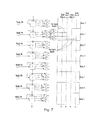
- FIG. 6 shows a diagram illustrating the selection of ready blocks for dispatch starting from the commit pointer and broadcasting the corresponding port assignments in accordance with one embodiment of the present invention.
- FIG. 7 shows an adder tree structure that is used to implement the selector array described in FIG. 6 in accordance with one embodiment of the present invention.
- FIG. 8 shows exemplary logic of a selector array adder tree in greater detail.
- FIG. 9 shows a parallel implementation of the adder tree for implementing a selector array in accordance with one embodiment of the present invention.
- FIG. 10 shows an exemplary diagram illustrating how adder X from FIG. 9 can be implemented by using carry save adders in accordance with one embodiment of the present invention.
- FIG. 11 shows a masking embodiment for masking ready bits for scheduling starting from the commit pointer and using the selector array adders in accordance with of the present invention.
- FIG. 12 shows an overview diagram of how register view entries are populated by register templates in accordance with one embodiment of the present invention.
- FIG. 13 shows a first embodiment for reduced register view footprint in accordance with one embodiment of the present invention.
- FIG. 14 shows a second embodiment for reduced register footprint in accordance with one embodiment of the present invention.
- FIG. 15 shows an exemplary format of the delta between snapshots in accordance with one embodiment of the present invention.
- FIG. 16 shows a diagram of a process for creating register template snapshots upon allocations of blocks of instructions in accordance with one embodiment of the present invention.
- FIG. 17 shows another diagram of a process for creating register template snapshots upon allocations of blocks of instructions in accordance with one embodiment of the present invention.
- FIG. 18 shows an overview diagram of hardware for implementing the serial implementation of creating a subsequent register template from a previous register template in accordance with one embodiment of the present invention.
- FIG. 19 shows an overview diagram of hardware for implementing a parallel implementation of creating a subsequent register template from a previous register template in accordance with one embodiment of the present invention.
- FIG. 20 shows an overview diagram of the hardware for instruction block-based execution and how it works with the source view, the instruction view, the register templates, and the register view in accordance with one embodiment of the present invention.
- FIG. 21 shows an example of a chunking architecture in accordance with one embodiment of the present invention.
- FIG. 22 shows a depiction of how threads are allocated in accordance with their block numbers and thread ID in accordance with one embodiment of the present invention.
- FIG. 23 shows an implementation of a scheduler using thread pointer maps that point to physical storage locations in order to manage multithreaded execution in accordance with one embodiment of the present invention.
- FIG. 24 shows another implementation of a scheduler using thread based pointer maps in accordance with one embodiment of the present invention.
- FIG. 25 shows a diagram of a dynamic calendar-based allocation of execution resources to threads in accordance with one embodiment of the present invention.
- FIG. 26 diagrams a dual dispatch process in accordance with one embodiment of the present invention.
- FIG. 27 diagrams a dual dispatch transient multiply-accumulate in accordance with one embodiment of the present invention.
- FIG. 28 diagrams a dual dispatch architecturally visible state multiply-add in accordance with one embodiment of the present invention.
- FIG. 29 shows an overview diagram of a fetch and formation of instruction blocks for execution on grouped execution units process in accordance with one embodiment of the present invention.
- FIG. 30 shows an exemplary diagram of instruction grouping in accordance with one embodiment of the present invention.
- two instructions are shown with a third auxiliary operation.
- FIG. 31 shows how half block pairs within a block stack maps onto the execution block units in accordance with one embodiment of the present invention.
- FIG. 32 shows a diagram depicting intermediate block results storage as a first level register file in accordance with one embodiment of the present invention.
- FIG. 33 shows an odd/even ports scheduler in accordance with one embodiment of the present invention.
- FIG. 34 shows a more detailed version of FIG. 33 where four execution units are shown receiving results from the scheduler array and writing outputs to a temporary register file segment.
- FIG. 35 shows a diagram depicting guest flag architecture emulation in accordance with one embodiment of the present invention.
- FIG. 36 shows a diagram illustrating the front end of the machine the scheduler and the execution units and a centralized flag register in accordance with one embodiment of the present invention.
- FIG. 37 shows a diagram of a centralized flag register emulation process as implemented by embodiments of the present invention.
- FIG. 38 shows a flowchart of the steps of a process 3800 of emulating centralized flag register behavior in a guest setting.
- references within the specification to “one embodiment” or “an embodiment” are intended to indicate that a particular feature, structure, or characteristic described in connection with the embodiment is included in at least one embodiment of the present invention.
- the appearance of the phrase “in one embodiment” in various places within the specification are not necessarily all referring to the same embodiment, nor are separate or alternative embodiments mutually exclusive of other embodiments.
- various features are described which may be exhibited by some embodiments and not by others.
- various requirements are described which may be requirements for some embodiments but not other embodiments.
- FIG. 1 shows an overview diagram of a process for grouping instructions into a block and tracking dependencies among the instructions by using a register template.
- FIG. 1 shows an instruction block having a header and a body.
- the block is created from a group of instructions.
- the block comprises an entity that encapsulates the group of instructions.
- the level of abstraction is raised to blocks instead of individual instructions. Blocks are processed for dispatch instead of individual instructions. Each block is labeled with a block number. The machine's out of order management job is thereby greatly simplified.
- One key feature is to find a way to manage a larger number of instructions being processed without greatly increasing the management overhead of the machine.
- Embodiments of the present invention achieves this objective by implementing instruction blocks, register templates and inheritance vectors.
- the header of the block lists and encapsulates all the sources and destinations of the instructions of the block.
- the header includes the destinations that update the register template.
- the sources included in the header will be concatenated with the block numbers stored in the register template.
- the number of instructions that are processed out of order determines the management complexity of the out of order machine. More out of order instructions leads to greater complexity. Sources need to compare against destinations of prior instructions in the out of order dispatch window of the processor.
- the register template has fields for each register from R0 to R63. Blocks write their respective block numbers into the register template fields that correspond to the block destinations. Each block reads the register fields that represent its register sources from the register template. When a block retires and writes its destination register contents into the register file, its number is erased from the register template. This means that those registers can be read as sources from the register file itself.
- the register template is updated each cycle of the machine whenever a block is allocated.
- prior snapshots of the register templates are stored into an array (e.g., the register view shown in FIG. 2 ), one per block. This information is retained until the corresponding block is retired. This allows the machine to recover from miss-predictions and flushes very quickly (e.g., by obtaining the last known dependency state).
- the register templates stored in the register view can be compressed (thereby saving storage space) by storing only the delta between successive snapshots (incremental changes between snapshots). In this manner the machine obtains a shrunk register view. Further compression can be obtained by only storing templates for blocks that have a branch instruction.
- a recovery point is needed other than a branch miss-prediction, then a recovery is first obtained at the branch recovery point, then state can be rebuilt out of allocating instructions (but not executing them) until the machine reaches the sought after recovery point.
- register template as used herein is synonymous with the term “inheritance vectors” as described in the earlier filed commonly assigned patent application “EXECUTING INSTRUCTION SEQUENCE CODE BLOCKS BY USING VIRTUAL CORES INSTANTIATED BY PARTITIONABLE ENGINES” by Mohammad Abdallah, filed on Mar. 23, 2012, Ser. No. 13/428,440, which is incorporated herein in its entirety.
- FIG. 2 shows an overview diagram of a register view, a source view, and an instruction view in accordance with one embodiment of the present invention.
- This figure shows one embodiment of a scheduler architecture (e.g., having a source view, instruction view, register view, etc.).
- a scheduler architecture e.g., having a source view, instruction view, register view, etc.
- Other implementations of a scheduler architecture that achieves the same functionality by combining or splitting one or more of the above cited structures are possible.
- FIG. 2 diagrams the functional entities supporting the operation of the register templates and retention of the machine state.
- the left-hand side of FIG. 2 shows register templates T0 through T4, with the arrows indicating the inheritance of information from one register template/inheritance vector to the next.
- the register view, source view, and instruction view each comprise data structures for storing information which relates to the blocks of instructions.
- FIG. 2 also shows an exemplary instruction block having a header and how the instruction block includes both sources and destinations for the registers of the machine.
- Information about the registers referred to by the blocks is stored in the register view data structure.
- Information about the sources referred to by the blocks is stored in the source view data structure.
- Information about the instructions themselves referred to by the blocks is stored in the instruction view data structure.
- the register templates/inheritance vectors themselves comprise data structures storing dependency and inheritance information referred to by the blocks.
- FIG. 3 shows a diagram that illustrates an exemplary register template and how the source view is populated by information from the register template in accordance with one embodiment of the present invention.
- the goal of the source view is to determine when particular blocks can be dispatched.
- a block When a block is dispatched it broadcasts its block number to all remaining blocks. Any matches in the source view for the block number (e.g., a compare) causes a ready bit (e.g., or some other type of indicator) to be set. When all ready bits are set (e.g., AND gate) the block is ready to be dispatched. Blocks are dispatched based on the readiness of other blocks they depend on.
- a find first circuit can be used to find the oldest block based on proximity to a commit pointer and subsequent blocks based on relative proximity to the commit pointer (e.g., working on each block's ready bit).
- the register template snapshot created at the arrival of block 20 is being examined.
- the register template has fields for each register from R0 to R63. Blocks write their respective block numbers into the register template fields that correspond to the block destinations. Each block reads the register fields that represent its register sources from the register template. The first number is the block that wrote to the register and the second number is the destination number of that block (which also corresponds to instruction number as shown in FIG. 3 ).
- block 20 when block 20 arrives, it reads the register template and looks up its own register sources in the register template to determine the latest block that wrote to each of its sources and populate the source view according to the updates that prior blocks' destinations (e.g., block 11 , as shown in FIG. 3 ) make to the register template. Subsequent blocks will update the register template with their own destinations. This is shown in the bottom left of FIG. 3 , where block 20 populates its sources: source 1, source 2, source 3, all the way to source 8.
- FIG. 4 shows a diagram illustrating a first embodiment for dependency broadcasting within source view.
- each column comprises an instruction block.
- a block When a block is allocated it marks (e.g., by writing 0) in all the block's columns where ever its sources have dependency on those blocks.
- any other block When any other block is dispatched its number is broadcasted across the exact column that relates to that block. It should be noted that writing a 1 is the default value indicating that there is no dependency on that block.
- FIG. 5 shows a diagram illustrating a second embodiment for dependency broadcasting within source view. This embodiment is organized by sources as opposed to being organized by blocks. This is shown by the sources S1 through S8 across the source view data structure.
- the FIG. 5 embodiment when all ready bits in a block are ready, that block is dispatched and its number is broadcast back to all the remaining blocks. The block number compares against all the numbers stored in the sources of the other blocks. If there is a match, the ready bit for that source is set. For example, if the block number broadcasted on source 1 equals 11 then the ready bit for source 1 of block 20 will be set.
- the FIG. 5 embodiment also shows how the compares are only enabled on the blocks between the commit pointer and the allocate pointer. All other blocks are invalid.
- FIG. 6 shows a diagram illustrating the selection of ready blocks for dispatch starting from the commit pointer and broadcasting the corresponding port assignments in accordance with one embodiment of the present invention.
- the source view data structure is shown on the left-hand side of FIG. 6 .
- the instruction view data structure is shown on the right-hand side of FIG. 6 .
- a selector array is shown between the source view and the instruction view. In this embodiment, the selector array dispatches four blocks per cycle via the four dispatch ports P1 through P4.
- blocks are selected for dispatch from the commit pointer wrapping around to allocate pointer (e.g., trying to honor dispatching older blocks first).
- the selector array is used to find the first 4 ready blocks starting from the commit pointer. It is desired to dispatch the oldest ready blocks.
- the selector array can be implemented by using an adder tree structure. This will be described in FIG. 7 below.
- FIG. 6 also shows how the selector array is coupled to each of the four ports that passed through the entries in the instruction view.
- the port couplings as port enables, and enable one of the four ports to be activated and for that instruction view entry to pass through down to the dispatch port and on to the execution units.
- dispatched blocks are broadcast back through the source view.
- the block numbers of selected blocks for dispatch are broadcast back (up to 4). This is shown on the far right-hand side of FIG. 6 .
- FIG. 7 shows an adder tree structure that is used to implement the selector array described in FIG. 6 in accordance with one embodiment of the present invention.
- the depicted adder tree implements the functionality of the selector array.
- the adder tree picks the first four ready blocks and mounts them to the four available ports for dispatch (e.g., read port 1 through read port 4). No arbitration is used.
- the actual logic that is used to specifically enable a specific port is explicitly shown in entry number 1. For the sake of clarity, the logic is not specifically show in the other entries.
- FIG. 7 shows one specific embodiment of how the direct selection of each particular port for block dispatch is implemented. It should be noted however, that alternatively, an embodiment that uses priority encoders can be implemented.
- FIG. 8 shows exemplary logic of a selector array adder tree in greater detail.
- logic is shown for a range exceed bit.
- the range exceed bit ensures that no more than four blocks will be selected for dispatch if a fifth block is ready the range exceed bit will not allow it to be dispatched if the first four also ready.
- the sum bits are S 0 to S 3 are both used to enable the dispatch port as well as propagation to the next adder stage in the serial implementation.
- FIG. 9 shows a parallel implementation of the adder tree for implementing a selector array in accordance with one embodiment of the present invention.
- the parallel implementation does not forward the sum from each adder to the next.
- each adder uses all its necessary inputs directly using a multiple input addition implementation, such as multi-input carry save adder trees. For example, the adder “X” sums all of the previous inputs.
- This parallel implementation is desirable in order to execute faster compute times (e.g., single cycle).
- FIG. 10 shows an exemplary diagram illustrating how adder X from FIG. 9 can be implemented by using carry save adders in accordance with one embodiment of the present invention.
- FIG. 10 shows a structure that can add 32 inputs in a single cycle. The structure is put together using 4-by-2 carry save adders.
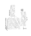
- FIG. 11 shows a masking embodiment for masking ready bits for scheduling starting from the commit pointer and using the selector array adders in accordance with of the present invention.
- the selector array adders are trying to select first 4 ready blocks to dispatch starting from the commit pointer potentially wrapping around to the allocate pointer.
- multi-input parallel adders are used. Additionally, in this implementation a source of these circular buffer is utilized.
- FIG. 11 shows how the ready bits are ANDed together with each of the two masks (individually or separately) and applied to the two adder trees in parallel.
- the first four are selected by using the two adder trees and comparing against the threshold of four.
- the “X” marks denote “exclude from the selection array for that adder tree” thus the “X” value is zero.
- the “Y” marks denote “do include in the selection array for that adder tree” thus the “Y” value is one.
- FIG. 12 shows an overview diagram of how register view entries are populated by register templates in accordance with one embodiment of the present invention.
- register view entries are populated by register templates.
- the register view stores snapshots of register templates for each block in sequence.
- a speculation e.g., a branch miss-prediction
- the register view has a latest valid snapshot before the invalid speculation point.
- the machine can roll back its state to the last valid snapshot by reading that register view entry and loading it into the base of the register template.
- Each entry of register view shows all of the register inheritance states. For example in the FIG. 12 embodiment, if the register view for block F is invalid, the machine state can be rolled back to an earlier last valid register template snapshot.
- FIG. 13 shows a first embodiment for reduced register view footprint in accordance with one embodiment of the present invention.
- the amount of memory needed to store the register view entries can be reduced by only storing those register view template snapshots that contain branch instructions.
- an exception e.g., a speculation is not valid, a branch miss-prediction, etc.
- the last valid snapshot can be rebuilt from the branch instruction that occurred prior to the exception. Instructions are fetched from the branch prior to the exception down to the exception in order to build the last valid snapshot. The instructions are fetched but they are not executed. As shown in FIG. 13 , only those snapshots that include branch instructions are saved in the reduced register view. This greatly reduces the amount of memory needed to store the register template snapshots.
- FIG. 14 shows a second embodiment for reduced register footprint in accordance with one embodiment of the present invention.
- the amount of memory needed to store the register view entries can be reduced by only storing a sequential subset of the snapshots (e.g., one out of every four snapshots).
- the change between successive snapshots can be stored as a “delta” from an original snapshot using a comparatively smaller amount of memory than full successive snapshots.
- an exception e.g., a speculation is not valid, a branch miss-prediction, etc.
- the “delta” from the original snapshot that occurred prior to the exception and the successive snapshots are used to rebuild the last valid snapshot.
- the initial original state can accumulate deltas to arrive to the state of the required snapshot.
- FIG. 15 shows an exemplary format of the delta between snapshots in accordance with one embodiment of the present invention.
- FIG. 15 shows an original snapshot and two deltas.
- R5 and R6 are the only registers being updated by B3. The rest of the entries are not changed.
- R1 and R7 are the only registers being updated by B2. The rest of the entries are not changed.
- FIG. 16 shows a diagram of a process for creating register template snapshots upon allocations of blocks of instructions in accordance with one embodiment of the present invention.
- the left-hand side of FIG. 16 shows two de-multiplexers and at the top of FIG. 16 is a snapshot register template.
- FIG. 16 shows a diagram for creating a subsequent register template from a previous register template (e.g., a serial implementation).
- This serial implementation shows how register template snapshots are created upon allocation of blocks of instructions. Those snapshots serves to capture the latest register architectural states update that are used for dependency tracking (e.g., as described in FIGS. 1 through 4 ) as well as updating the register view for handling miss-predictions/exceptions (e.g., as described in FIGS. 12 through 15 ).
- the de-mux functions by selecting which incoming source is passed on. For example, register R2 will de-mux to a 1 at the second output, while R8 will de-mux to a 1 at the seventh output, and so on.
- FIG. 17 shows another diagram of a process for creating register template snapshots upon allocations of blocks of instructions in accordance with one embodiment of the present invention.
- the FIG. 17 embodiment also shows the creating of a subsequent register template from a previous register template.
- the FIG. 17 embodiment also shows an example of register template block inheritance.
- This Figure shows an example of how the register template is updated from allocated block numbers. For example, block Bf updates R2, R8, and R10. Bg updates R1 and R9.
- the dotted arrows indicate that the values are inherited from the prior snapshot. This process proceeds all the way down to block Bi. Thus, for example, since no snapshot updated register R7, its original value Bb will have propagated all the way down.
- FIG. 18 shows an overview diagram of hardware for implementing the serial implementation of creating a subsequent register template from a previous register template in accordance with one embodiment of the present invention.
- the de-multiplexer is used to control a series of two input multiplexers which of two block numbers will be propagated down to the next stage. It can either be the block number from the previous stage or the current block number.
- FIG. 19 shows an overview diagram of hardware for implementing a parallel implementation of creating a subsequent register template from a previous register template in accordance with one embodiment of the present invention.
- This Parallel implementation uses special encoded multiplexer controls to create a subsequent register template from a previous register template.
- FIG. 20 shows an overview diagram of the hardware for instruction block-based execution and how it works with the source view, the instruction view, the register templates, and the register view in accordance with one embodiment of the present invention.
- the allocator scheduler in dispatcher receives instructions fetched by the machine's front end. These instructions go through block formation in the manner we described earlier. As described earlier the blocks yield register templates and these register templates are used to populate the register view. From the source view the sources are transferred to the register file hierarchy and there are broadcasts back to the source view in the manner described above.
- the instruction view transfers instructions to the execution units. The instructions are executed by the execution units as the sources needed by the instructions coming from the register file hierarchy. These executed instructions are then transferred out of the execution unit and back into the register file hierarchy.
- FIG. 21 shows an example of a chunking architecture in accordance with one embodiment of the present invention.
- the importance of chunking is that it reduces the number of write ports into each scheduler entry from 4 to 1 by using the four multiplexers shown, while still densely packing all the entries without forming bubbles.
- chunking can be seen by the following example (e.g., noting that allocation of blocks in each cycle starts at the top position, in this case B0). Assuming in cycle 1, three blocks of instructions are to be allocated to the scheduler entries (e.g., the three blocks will occupy the first 3 entries in the scheduler). In the next cycle (e.g., cycle 2) another two blocks of instructions are to be allocated. In order to avoid creating bubbles in the scheduler array entries, the scheduler array entries have to be built with support for four write ports. This is expensive in terms of power consumption, timing, area, and the like.
- the chunking structure above simplifies all scheduler arrays to only have one write port by using the multiplexing structure before allocating to the arrays. In the above example, the B0 in cycle two will be selected by the last mux while B1 in cycle two will be selected by the first mux (e.g., going from left to right).
- each for entry chunk only needs one write port per entry and four read ports per entry.
- cost is made up many times over in the savings from not having to implement four write ports per entry, as there can be very many entries.
- FIG. 21 also shows an intermediate allocation buffer. If the scheduler arrays cannot accept all the chunks sent to them, then they can be stored temporarily in the intermediate allocation buffer. When the scheduler arrays have free space, the chunks will be transferred from the intermediate allocation buffer to the scheduler arrays.
- FIG. 22 shows a depiction of how threads are allocated in accordance with their block numbers and thread ID in accordance with one embodiment of the present invention.
- Blocks are allocated to the scheduler array via a chunking implementation as described above.
- Each of the thread blocks maintain a sequential order among themselves using the block number.
- the blocks from different threads can be interleaved (e.g., Blocks for thread Th1 and blocks for thread Th2 are interleaved in the scheduler array. In this manner, blocks from different threads are present within the scheduler array.
- FIG. 23 shows an implementation of a scheduler using thread pointer maps that point to physical storage locations in order to manage multithreaded execution in accordance with one embodiment of the present invention.
- management of the threads is implemented through the control of the thread maps.
- FIG. 23 shows thread 1 map and thread 2 map.
- the maps track the location of the blocks of the individual thread.
- the entries in the map 0.2 physical storage locations the entries in the map are allocated to blocks belonging to that thread.
- each thread has an allocation counter that counts for both threads. The overall count cannot exceed N divided by 2 (e.g., exceeding space available).
- the allocation counters have adjustable thresholds in order to implement fairness in the allocation of the total entries from the pool.
- the allocation counters can prevent one thread from using all of the available space.
- FIG. 24 shows another implementation of a scheduler using thread based pointer maps in accordance with one embodiment of the present invention.
- FIG. 24 shows a relationship between the commit pointer and the allocation pointer. As shown, each thread has a commit pointer and an allocate pointer the arrow shows how reality pointer for thread 2 can wrap around the physical storage allocating blocks B1 and B2, but it cannot allocate block B9 until the commit pointer for thread 2 moves down. This is shown by the position of the commit pointer of thread 2 and the strikethrough. The right-hand side of FIG. 24 shows a relationship between the allocation of blocks and the commit pointer as it moves around counterclockwise.
- FIG. 25 shows a diagram of a dynamic calendar-based allocation of execution resources to threads in accordance with one embodiment of the present invention. Fairness can be dynamically controlled using the allocate counters based on the forward progress of each thread. If both threads are making substantial forward progress, then both allocation counters are set to the same threshold (e.g., 9). However if one thread makes slow forward progress, such as suffering from an L2 cache miss or such events, then the ratio of the threshold counters can be adjusted in the favor of the thread that is still making substantial forward progress.
- the ratio of the threshold counters can be adjusted in the favor of the thread that is still making substantial forward progress.
- the ratio can be completely adjusted to the other thread with the exception of a single return entry that is reserved for the suspended thread to signal the release of the wait state.
- the process starts off with a ratio of 50%:50%.
- the front end of the pipeline stalls any further fetch into the pipeline or allocation into the scheduler of thread 2 blocks.
- those entries will be made available for thread 1 allocation until the point where the new dynamic ratio of thread allocation is achieved. For example, 3 out the recently retired thread 2 blocks will be returned to the pool for allocation to thread 1 instead of thread 2, making the thread 1 to thread 2 ratio 75%:25%.
- a stall of thread 2 blocks in the front of the pipeline might require flushing those blocks from the front of the pipeline if there is no hardware mechanism to bypass them (e.g., by thread 1 blocks by passing the stalled thread 2 blocks).
- FIG. 26 diagrams a dual dispatch process in accordance with one embodiment of the present invention.
- Multi-dispatch generally encompasses dispatching a block (having multiple instruction within) multiple times such that different instructions with the block can execute on each pass through the execution units.
- One example would be a dispatch of an address calculation instruction followed by a subsequent dispatch that consumes the resulting data.
- Another example would be a floating point operation, where the first part is executed as fixed point operation and the second part is executed to complete the operation by performing rounding, flag generation/calculation, exponent adjustment or the like.
- Blocks are allocated, committed and retired atomically as a single entity.
- a main benefit of multi-dispatch is that it avoids allocating multiple separate blocks into the machine window, thereby making the machine window effectively larger.
- a larger machine window means more opportunities for optimization and reordering.
- FIG. 26 there is an instruction block depicted.
- This block cannot be dispatched in a single cycle because there is latency between the load address calculation and the load returning data from the caches/memory. So this block is first dispatched with its intermediate result being held as a transient state (its result is being delivered on the fly to the second dispatch without being visible to the architectural state). The first dispatch sends the two components 1 and 2 that are used in the address calculation and the dispatch of the LA. The second dispatch sends components 3 and 4 which are the execution parts of the load data upon the load returning data from the caches/memory.
- FIG. 26 there is a floating point multiply accumulate operation depicted.
- dual dispatch is used, as the multiply accumulate figure shows.
- the first dispatch is a fixed point multiply as shown.
- the second dispatch is a floating point addition rounding as shown. When both of these dispatched instructions execute, they effectively perform the floating point multiply/accumulate.
- FIG. 27 diagrams a dual dispatch transient multiply-accumulate in accordance with one embodiment of the present invention.
- the first dispatch is the integer 32 bit multiply
- the second dispatch is the integer accumulate add.
- State communicated between the first dispatch and the second dispatch (the result of the multiply) is transient and not architecturally visible.
- the transient storage in one implementation can hold results of more than one multiplier and can tag them to identify the corresponding multiply accumulate pair, thereby allowing intermix of multiple multiply accumulate pairs being dispatch in an arbitrary fashion (e.g., interleaved, etc.).
- FIG. 28 diagrams a dual dispatch architecturally visible state multiply-add in accordance with one embodiment of the present invention.
- the first dispatch is the single precision multiply
- the second dispatch is the single precision add.
- state information communicated between the first dispatch and the second dispatch e.g., the result of the multiply
- this storage is an architecture state register.
- FIG. 29 shows an overview diagram of a fetch and formation of instruction blocks for execution on grouped execution units process in accordance with one embodiment of the present invention.
- Embodiments of the present invention utilize a process whereby instructions are fetched and formed as blocks by the hardware or dynamic converter/JIT.
- the instructions in the blocks are organized such that a result of an early instruction in the block feeds a source of a subsequent instruction in the block. This is shown by the dotted arrows in the block of instructions. This property enables the block to execute efficiently on the stacked execution units of the execution block. Instructions can also be grouped even if they can execute in parallel, such as if they share the same source (not shown explicitly in this figure).
- One alternative to forming the blocks in hardware is to form them in software (statically or at runtime) where instruction pairs, triplets, quads, etc., are formed.
- FIG. 30 shows an exemplary diagram of instruction grouping in accordance with one embodiment of the present invention.
- two instructions are shown with a third auxiliary operation.
- the left-hand side of FIG. 31 instruction block comprising an upper half block/1 slot and a lower half block/1 slot.
- the vertical arrows coming down from the top indicates sources coming into the block while the vertical arrows going down from the bottom indicate destinations going back to memory. Proceeding from the left-hand side of FIG. 3 towards the right-hand side, different instruction combinations that are possible are illustrated.
- each half block can receive three sources and can pass on two destinations.
- OP1 and OP2 are normal operations.
- Auxiliary OPs are auxiliary operations such as a logical, a shift, a move, a sign extend, a branch, etc.
- the benefit of dividing the block into two halves is to allow the benefit of having each half dispatch on its own independently or otherwise together as one block dynamically (either for port utilization or because of resource constrains) based on dependency resolution, thus having better utilization of execution times, at the same time having the 2 halves correspond to one block allows the machine to abstract the complexity of 2 half blocks to be managed like one block (i.e. at allocate and retirement).
- FIG. 31 shows how half block pairs within a block stack maps onto the execution block units in accordance with one embodiment of the present invention.
- each execution block has two slots, slot 1 and slot 2.
- the objective is to s map the block onto the execution units such that the first half block executes on slot 1 and the second half block executes on slot 2.
- the objective is to allow the 2 half blocks to dispatch independently if the instruction group of each half block does not depend on the other half.
- the paired arrows coming into the execution block from the top are two 32-bit words of a source.
- the paired arrows leaving the execution block going down are two 32-bit words of a destination. Going from left to right of FIG. 31 , different exemplary combinations of instructions are shown that are capable of being stacked onto the execution block units.
- FIG. 31 summarizes how the pairs of half blocks execute in a full block context or any half block context.
- Each of the s Execution blocks have two slots/half blocks and each one of the half bocks/execution slots executes either a single, paired or triplet grouped operations.
- the second is atomic parallel halves (which refers to half blocks that can execute in parallel because there is no dependency between the 2 halves but they are forced to execute together as one block because the resource sharing between the 2 halves make it preferred or necessary for the two halves to execute together atomically within the constraint of the resources available in each execution block).
- the third type is atomic serial halves s (which requires the first half to forward data to the second half, through transient forwarding with or without internal storage).
- the fourth type is sequential halves (as in dual dispatch) where the 2 nd half depend on the first half and is dispatched on a later cycle than the first one and forwards the data through external storage that are tracked for dependency resolution, similar to the dual dispatch case.
- FIG. 32 shows a diagram depicting intermediate block results storage as a first level register file in accordance with one embodiment of the present invention.
- Each group of registers represent a block of instructions (representing two half blocks) in which both 32 bit results as well as 64 bits results can be supported by using two 32 bit registers to support one 64 bit register.
- the storage per block assumes a virtual block storage, which means two half blocks from different blocks can write into the same virtual block storage. Combined results' storage of two half blocks that make up one virtual block storage.
- FIG. 33 shows an odd/even ports scheduler in accordance with one embodiment of the present invention.
- the result storage is asymmetrical. Some of the result storage is three 64 bit result registers per half block while others are one 64 bit result register per half block, however alternative implementation can use symmetrical storage per half block and additionally could also employ 64-bit and 32-bit partition as described in FIG. 32 . In these embodiments, storage is assigned per half block, as opposed to per block. This implementation reduces the number of ports needed for dispatch by using them as odd or even.
- FIG. 34 shows a more detailed version of FIG. 33 where four execution units are shown receiving results from the scheduler array and writing outputs to a temporary register file segment.
- the ports are attached at even and odd intervals.
- the left side of the scheduling array shows block numbers and the right side shows half block numbers.
- Each core has even and odd ports into the scheduling array, where each port is connected to an odd or even half block position.
- the even ports and their corresponding half blocks can reside in a different core than the odd ports and their corresponding half blocks.
- the odd and even ports will be distributed across multiple different cores as shown in this figure.
- the cores can be physical cores or virtual cores.
- one half of a block can be dispatched independently from the other half of the block.
- both halves of a block need to be dispatched simultaneously to the same execution block units.
- the two halves of a block need to be dispatched sequentially (the second half after the first half).
- FIG. 35 shows a diagram depicting guest flag architecture emulation in accordance with one embodiment of the present invention.
- the left-hand side of FIG. 35 shows a centralized flag register having five flags.
- the right-hand side of FIG. 35 shows a distributed flag architecture having distributed flag registers wherein the flags are distributed amongst registers themselves.
- Distributed flag architecture can also be implemented by using multiple independent flag registers as opposed to a flag field associated with a data register.
- data registers can be implemented as R0 to R15 while independent flag registers can be implemented as F0 to F3. Those flag registers in this case are not associated directly with the data registers.
- FIG. 36 shows a diagram illustrating the front end of the machine the scheduler and the execution units and a centralized flag register in accordance with one embodiment of the present invention.
- the front end categorizes incoming instructions based on the manner in which they update guest instruction flags.
- the guest instructions are categorized into 4 native instruction types, T1, T2, T3, and T4.
- T1-T4 are instruction types that indicate which flag fields that each guest instruction type updates.
- Guest instruction types update different guest instruction flags, based on their type. For example, logical guest instructions update T1 native instructions.
- FIG. 37 shows a diagram of a centralized flag register emulation process as implemented by embodiments of the present invention.
- the actors in FIG. 37 comprise a latest update type table, a renaming table extension, physical registers, and distributed flag registers.
- FIG. 37 is now described by the flowchart of FIG. 38 .
- FIG. 38 shows a flowchart of the steps of a process 3800 of emulating centralized flag register behavior in a guest setting.
- the front end/dynamic converter categorizes incoming instructions based on the manner in which they update guest instruction flags.
- the guest instructions are categorized into four flag architectural types, T1, T2, T3, and T4.
- T1-T4 are instruction types that indicate which flag fields that each guest instruction type updates. Guest instruction types update different guest flags, based on their type. For example, logical guest instructions update T1 type flags, shift guest instructions update T2 type flags, arithmetic guest instructions update T3 type flags, and special guest instructions update type T4 flags.
- guest instructions can be architectural instruction representation while native can be what the machine internally executes (e.g., microcode).
- guest instructions can be instructions from an emulated architecture (e.g., x86, java, ARM code, etc.).
- step 3802 the order in which those instruction types update their respective guest flags is recorded in a latest update type table data structure. In one embodiment, this action is performed by the front end of the machine.
- step 3803 when those instruction types reach the Scheduler (the in-order part of the allocation/renaming stage), the scheduler assigns an implicit physical destination that corresponds to the architectural type and records that assignment in a renaming/mapping table data structure.
- step 3804 when a subsequent guest instruction reaches the allocation/renaming stage in the scheduler, and that instruction wants to read guest flag fields, (a) the machine determines which flag architectural types need to be accessed to perform the read. (b) if all needed flags are found in the same latest update flag type (e.g., as determined by the latest update type table), then the corresponding physical register (e.g., that maps to that latest flag type) is read to obtain the needed flags. (c) if all needed flags cannot be found in a same latest update flag type, then each flag needs to be read from the corresponding physical register that maps to the individual latest update flag type.
- the machine determines which flag architectural types need to be accessed to perform the read.
- the corresponding physical register e.g., that maps to that latest flag type
- each flag is being read individually from the physical register that holds its latest value that was lastly updated, as tracked by the latest update flag type table.
Abstract
Description
Claims (18)
Priority Applications (2)
| Application Number | Priority Date | Filing Date | Title |
|---|---|---|---|
| US14/213,854 US9575762B2 (en) | 2013-03-15 | 2014-03-14 | Method for populating register view data structure by using register template snapshots |
| US15/408,269 US10198266B2 (en) | 2013-03-15 | 2017-01-17 | Method for populating register view data structure by using register template snapshots |
Applications Claiming Priority (2)
| Application Number | Priority Date | Filing Date | Title |
|---|---|---|---|
| US201361799006P | 2013-03-15 | 2013-03-15 | |
| US14/213,854 US9575762B2 (en) | 2013-03-15 | 2014-03-14 | Method for populating register view data structure by using register template snapshots |
Related Child Applications (1)
| Application Number | Title | Priority Date | Filing Date |
|---|---|---|---|
| US15/408,269 Continuation US10198266B2 (en) | 2013-03-15 | 2017-01-17 | Method for populating register view data structure by using register template snapshots |
Publications (2)
| Publication Number | Publication Date |
|---|---|
| US20140281428A1 US20140281428A1 (en) | 2014-09-18 |
| US9575762B2 true US9575762B2 (en) | 2017-02-21 |
Family
ID=51533995
Family Applications (2)
| Application Number | Title | Priority Date | Filing Date |
|---|---|---|---|
| US14/213,854 Active US9575762B2 (en) | 2013-03-15 | 2014-03-14 | Method for populating register view data structure by using register template snapshots |
| US15/408,269 Active 2034-08-24 US10198266B2 (en) | 2013-03-15 | 2017-01-17 | Method for populating register view data structure by using register template snapshots |
Family Applications After (1)
| Application Number | Title | Priority Date | Filing Date |
|---|---|---|---|
| US15/408,269 Active 2034-08-24 US10198266B2 (en) | 2013-03-15 | 2017-01-17 | Method for populating register view data structure by using register template snapshots |
Country Status (3)
| Country | Link |
|---|---|
| US (2) | US9575762B2 (en) |
| TW (1) | TWI522909B (en) |
| WO (1) | WO2014150806A1 (en) |
Cited By (7)
| Publication number | Priority date | Publication date | Assignee | Title |
|---|---|---|---|---|
| US20180060076A1 (en) * | 2013-03-15 | 2018-03-01 | Intel Corporation | Method for implementing a reduced size register view data structure in a microprocessor |
| US10521239B2 (en) | 2011-11-22 | 2019-12-31 | Intel Corporation | Microprocessor accelerated code optimizer |
| US10564975B2 (en) | 2011-03-25 | 2020-02-18 | Intel Corporation | Memory fragments for supporting code block execution by using virtual cores instantiated by partitionable engines |
| US10585670B2 (en) | 2006-11-14 | 2020-03-10 | Intel Corporation | Cache storing data fetched by address calculating load instruction with label used as associated name for consuming instruction to refer |
| US10740126B2 (en) | 2013-03-15 | 2020-08-11 | Intel Corporation | Methods, systems and apparatus for supporting wide and efficient front-end operation with guest-architecture emulation |
| US11163720B2 (en) | 2006-04-12 | 2021-11-02 | Intel Corporation | Apparatus and method for processing an instruction matrix specifying parallel and dependent operations |
| US11656875B2 (en) | 2013-03-15 | 2023-05-23 | Intel Corporation | Method and system for instruction block to execution unit grouping |
Families Citing this family (17)
| Publication number | Priority date | Publication date | Assignee | Title |
|---|---|---|---|---|
| EP2616928B1 (en) | 2010-09-17 | 2016-11-02 | Soft Machines, Inc. | Single cycle multi-branch prediction including shadow cache for early far branch prediction |
| WO2012135041A2 (en) | 2011-03-25 | 2012-10-04 | Soft Machines, Inc. | Register file segments for supporting code block execution by using virtual cores instantiated by partitionable engines |
| EP2689327B1 (en) | 2011-03-25 | 2021-07-28 | Intel Corporation | Executing instruction sequence code blocks by using virtual cores instantiated by partitionable engines |
| CN103649931B (en) | 2011-05-20 | 2016-10-12 | 索夫特机械公司 | For supporting to be performed the interconnection structure of job sequence by multiple engines |
| WO2012162188A2 (en) | 2011-05-20 | 2012-11-29 | Soft Machines, Inc. | Decentralized allocation of resources and interconnect structures to support the execution of instruction sequences by a plurality of engines |
| KR101703401B1 (en) | 2011-11-22 | 2017-02-06 | 소프트 머신즈, 인크. | An accelerated code optimizer for a multiengine microprocessor |
| KR102063656B1 (en) | 2013-03-15 | 2020-01-09 | 소프트 머신즈, 인크. | A method for executing multithreaded instructions grouped onto blocks |
| WO2014150806A1 (en) | 2013-03-15 | 2014-09-25 | Soft Machines, Inc. | A method for populating register view data structure by using register template snapshots |
| US10275255B2 (en) | 2013-03-15 | 2019-04-30 | Intel Corporation | Method for dependency broadcasting through a source organized source view data structure |
| US9891924B2 (en) | 2013-03-15 | 2018-02-13 | Intel Corporation | Method for implementing a reduced size register view data structure in a microprocessor |
| US9569216B2 (en) | 2013-03-15 | 2017-02-14 | Soft Machines, Inc. | Method for populating a source view data structure by using register template snapshots |
| US9904625B2 (en) | 2013-03-15 | 2018-02-27 | Intel Corporation | Methods, systems and apparatus for predicting the way of a set associative cache |
| US9886279B2 (en) * | 2013-03-15 | 2018-02-06 | Intel Corporation | Method for populating and instruction view data structure by using register template snapshots |
| US9632825B2 (en) | 2013-03-15 | 2017-04-25 | Intel Corporation | Method and apparatus for efficient scheduling for asymmetrical execution units |
| US9811342B2 (en) | 2013-03-15 | 2017-11-07 | Intel Corporation | Method for performing dual dispatch of blocks and half blocks |
| WO2014150971A1 (en) | 2013-03-15 | 2014-09-25 | Soft Machines, Inc. | A method for dependency broadcasting through a block organized source view data structure |
| US11681531B2 (en) | 2015-09-19 | 2023-06-20 | Microsoft Technology Licensing, Llc | Generation and use of memory access instruction order encodings |
Citations (99)
| Publication number | Priority date | Publication date | Assignee | Title |
|---|---|---|---|---|
| US3044951A (en) | 1958-06-05 | 1962-07-17 | Texaco Inc | Hydrocarbon conversion process |
| US3046775A (en) | 1957-09-25 | 1962-07-31 | American Cyanamid Co | Apparatus for treating reticulate material |
| US4727487A (en) | 1984-07-31 | 1988-02-23 | Hitachi, Ltd. | Resource allocation method in a computer system |
| US5404470A (en) * | 1991-11-26 | 1995-04-04 | Matsushita Electric Industrial Co., Ltd. | Information processing apparatus for processing instructions by out-of-order execution |
| US5724565A (en) | 1995-02-03 | 1998-03-03 | International Business Machines Corporation | Method and system for processing first and second sets of instructions by first and second types of processing systems |
| US5751982A (en) | 1995-03-31 | 1998-05-12 | Apple Computer, Inc. | Software emulation system with dynamic translation of emulated instructions for increased processing speed |
| US5761476A (en) | 1993-12-30 | 1998-06-02 | Intel Corporation | Non-clocked early read for back-to-back scheduling of instructions |
| US5819088A (en) | 1993-03-25 | 1998-10-06 | Intel Corporation | Method and apparatus for scheduling instructions for execution on a multi-issue architecture computer |
| US5911057A (en) | 1995-12-19 | 1999-06-08 | Texas Instruments Incorporated | Superscalar microprocessor having combined register and memory renaming circuits, systems, and methods |
| US6216215B1 (en) | 1998-04-02 | 2001-04-10 | Intel Corporation | Method and apparatus for senior loads |
| US6308323B1 (en) | 1998-05-28 | 2001-10-23 | Kabushiki Kaisha Toshiba | Apparatus and method for compiling a plurality of instruction sets for a processor and a media for recording the compiling method |
| US6345357B1 (en) | 1999-02-02 | 2002-02-05 | Mitsubishi Denki Kabushiki Kaisha | Versatile branch-less sequence control of instruction stream containing step repeat loop block using executed instructions number counter |
| US20020029308A1 (en) | 1999-02-17 | 2002-03-07 | Boris Babaian | Method for emulating hardware features of a foreign architecture in a host operating system environment |
| US20020062435A1 (en) | 1998-12-16 | 2002-05-23 | Mario D. Nemirovsky | Prioritized instruction scheduling for multi-streaming processors |
| US6490673B1 (en) | 1998-11-27 | 2002-12-03 | Matsushita Electric Industrial Co., Ltd | Processor, compiling apparatus, and compile program recorded on a recording medium |
| US6529928B1 (en) | 1999-03-23 | 2003-03-04 | Silicon Graphics, Inc. | Floating-point adder performing floating-point and integer operations |
| US6557095B1 (en) * | 1999-12-27 | 2003-04-29 | Intel Corporation | Scheduling operations using a dependency matrix |
| US20030093776A1 (en) | 2001-11-14 | 2003-05-15 | Ronald Hilton | Memory address prediction under emulation |
| TW544626B (en) | 2000-02-04 | 2003-08-01 | Ibm | Method and apparatus for verifying that instructions are pipelined in correct architectural sequence |
| US20030233394A1 (en) | 2002-06-14 | 2003-12-18 | Rudd Kevin W. | Method and apparatus for ensuring fairness and forward progress when executing multiple threads of execution |
| US6668316B1 (en) | 1999-02-17 | 2003-12-23 | Elbrus International Limited | Method and apparatus for conflict-free execution of integer and floating-point operations with a common register file |
| US6704860B1 (en) | 2000-07-26 | 2004-03-09 | International Business Machines Corporation | Data processing system and method for fetching instruction blocks in response to a detected block sequence |
| US20040078538A1 (en) | 2002-10-22 | 2004-04-22 | Bala Dutt | System and method for goal-based scheduling of blocks of code for concurrent execution |
| US20040098567A1 (en) | 1995-08-16 | 2004-05-20 | Microunity Systems Engineering, Inc. | System and software for catenated group shift instruction |
| US20040158822A1 (en) | 2002-02-06 | 2004-08-12 | Sandham John H. | Condition code flag emulation for program code conversion |
| US20040187123A1 (en) | 2003-02-13 | 2004-09-23 | Marc Tremblay | Selectively unmarking load-marked cache lines during transactional program execution |
| TW200422949A (en) | 2002-12-05 | 2004-11-01 | Ibm | Processor virtualization mechanism via an enhanced restoration of hard architected states |
| US20050114603A1 (en) | 2003-11-24 | 2005-05-26 | International Business Machines Corporation | Method and circuit for reading and writing an instruction buffer |
| US20050120194A1 (en) | 2003-08-28 | 2005-06-02 | Mips Technologies, Inc. | Apparatus, method, and instruction for initiation of concurrent instruction streams in a multithreading microprocessor |
| US6948172B1 (en) | 1993-09-21 | 2005-09-20 | Microsoft Corporation | Preemptive multi-tasking with cooperative groups of tasks |
| US20050289530A1 (en) | 2004-06-29 | 2005-12-29 | Robison Arch D | Scheduling of instructions in program compilation |
| US7020879B1 (en) | 1998-12-16 | 2006-03-28 | Mips Technologies, Inc. | Interrupt and exception handling for multi-streaming digital processors |
| US20060161921A1 (en) | 2003-08-28 | 2006-07-20 | Mips Technologies, Inc. | Preemptive multitasking employing software emulation of directed exceptions in a multithreading processor |
| US20060179281A1 (en) | 2005-02-04 | 2006-08-10 | Mips Technologies, Inc. | Multithreading instruction scheduler employing thread group priorities |
| US20060179257A1 (en) | 2005-02-09 | 2006-08-10 | Chu Sam G | Apparatus and method for providing multiple reads/writes using a 2read/2write register file array |
| US20060212687A1 (en) | 2005-03-18 | 2006-09-21 | Marvell World Trade Ltd. | Dual thread processor |
| US20060230409A1 (en) | 2005-04-07 | 2006-10-12 | Matteo Frigo | Multithreaded processor architecture with implicit granularity adaptation |
| US20060230243A1 (en) | 2005-04-06 | 2006-10-12 | Robert Cochran | Cascaded snapshots |
| US20060282839A1 (en) | 2005-06-13 | 2006-12-14 | Hankins Richard A | Mechanism for monitoring instruction set based thread execution on a plurality of instruction sequencers |
| US20070006231A1 (en) | 2005-06-30 | 2007-01-04 | Hong Wang | Mechanism for instruction set based thread execution on a plurality of instruction sequencers |
| US20070198665A1 (en) | 2006-02-20 | 2007-08-23 | Luca De Matteis | Method of configuring devices in a telecommunications network |
| US20080016507A1 (en) | 1998-11-16 | 2008-01-17 | Esmertec Ag | Computer system |
| TW200813766A (en) | 2006-04-14 | 2008-03-16 | Cadence Design Systems Iinc | Method and system for simulating state retention of an RTL design |
| US20080104598A1 (en) | 2006-10-26 | 2008-05-01 | Benq Corporation | Systems and methods for operation scheduling |
| US20080148237A1 (en) | 2006-04-24 | 2008-06-19 | Jiang Guowen | Debugging method and apparatus for developing telecom-class service based on model driven |
| US20080250227A1 (en) | 2007-04-04 | 2008-10-09 | Linderman Michael D | General Purpose Multiprocessor Programming Apparatus And Method |
| US20080320476A1 (en) | 2007-06-25 | 2008-12-25 | Sonics, Inc. | Various methods and apparatus to support outstanding requests to multiple targets while maintaining transaction ordering |
| US20090019264A1 (en) | 2007-07-11 | 2009-01-15 | Correale Jr Anthony | Adaptive execution cycle control method for enhanced instruction throughput |
| US20090113170A1 (en) | 2006-04-12 | 2009-04-30 | Mohammad A Abdallah | Apparatus and Method for Processing an Instruction Matrix Specifying Parallel and Dependent Operations |
| US20090138670A1 (en) | 2007-11-27 | 2009-05-28 | Microsoft Corporation | software-configurable and stall-time fair memory access scheduling mechanism for shared memory systems |
| US20090150647A1 (en) | 2007-12-07 | 2009-06-11 | Eric Oliver Mejdrich | Processing Unit Incorporating Vectorizable Execution Unit |
| US20090165007A1 (en) | 2007-12-19 | 2009-06-25 | Microsoft Corporation | Task-level thread scheduling and resource allocation |
| US20090282101A1 (en) | 1998-09-10 | 2009-11-12 | Vmware, Inc. | Mechanism for providing virtual machines for use by multiple users |
| TW200949690A (en) | 2008-05-26 | 2009-12-01 | Faraday Tech Corp | Processor and early execution method of data load thereof |
| US20090307450A1 (en) | 2007-04-11 | 2009-12-10 | Dot Hill Systems Corporation | Snapshot Preserved Data Cloning |
| US20090328053A1 (en) | 2004-06-04 | 2009-12-31 | Sun Microsystems, Inc. | Adaptive spin-then-block mutual exclusion in multi-threaded processing |
| US20100100690A1 (en) | 2008-10-21 | 2010-04-22 | Microsoft Corporation | System to reduce interference in concurrent programs |
| US7707578B1 (en) | 2004-12-16 | 2010-04-27 | Vmware, Inc. | Mechanism for scheduling execution of threads for fair resource allocation in a multi-threaded and/or multi-core processing system |
| WO2010049585A1 (en) | 2008-10-30 | 2010-05-06 | Nokia Corporation | Method and apparatus for interleaving a data block |
| US20100115244A1 (en) | 2005-02-04 | 2010-05-06 | Mips Technologies, Inc. | Multithreading microprocessor with optimized thread scheduler for increasing pipeline utilization efficiency |
| US20100154042A1 (en) | 2008-12-12 | 2010-06-17 | International Business Machines Corporation | Design of virtual machine |
| US20100161948A1 (en) * | 2006-11-14 | 2010-06-24 | Abdallah Mohammad A | Apparatus and Method for Processing Complex Instruction Formats in a Multi-Threaded Architecture Supporting Various Context Switch Modes and Virtualization Schemes |
| US7757065B1 (en) | 2000-11-09 | 2010-07-13 | Intel Corporation | Instruction segment recording scheme |
| US20100205603A1 (en) | 2009-02-09 | 2010-08-12 | Unisys Corporation | Scheduling and dispatching tasks in an emulated operating system |
| TWI329437B (en) | 2007-01-31 | 2010-08-21 | Univ Nat Yunlin Sci & Tech | |
| TWI331282B (en) | 2005-12-30 | 2010-10-01 | Intel Corp | Address space emulation method, processor, computer system, and computer-readable storage medium |
| US20100280996A1 (en) | 2009-05-04 | 2010-11-04 | Moka5, Inc. | Transactional virtual disk with differential snapshots |
| US20100286976A1 (en) | 2006-11-20 | 2010-11-11 | Et International, Inc. | Systems and Methods for Logic Verification |
| US20100299671A1 (en) * | 2009-05-19 | 2010-11-25 | Microsoft Corporation | Virtualized thread scheduling for hardware thread optimization |
| US20100306503A1 (en) | 2009-06-01 | 2010-12-02 | Via Technologies, Inc. | Guaranteed prefetch instruction |
| US20100325394A1 (en) | 2009-06-23 | 2010-12-23 | Golla Robert T | System and Method for Balancing Instruction Loads Between Multiple Execution Units Using Assignment History |
| US20110055479A1 (en) | 2009-08-28 | 2011-03-03 | Vmware, Inc. | Thread Compensation For Microarchitectural Contention |
| US20110067016A1 (en) | 2008-07-10 | 2011-03-17 | Rocketick Technologies Ltd. | Efficient parallel computation on dependency problems |
| US20110093857A1 (en) | 2009-10-20 | 2011-04-21 | Infineon Technologies Ag | Multi-Threaded Processors and Multi-Processor Systems Comprising Shared Resources |
| TWI352288B (en) | 2005-01-14 | 2011-11-11 | Verigy Pte Ltd Singapore | Method for optimizing test order, and machine-read |
| US20120023318A1 (en) | 2010-07-22 | 2012-01-26 | Xing Bin C | Providing platform independent memory logic |
| US20120066483A1 (en) | 2010-09-15 | 2012-03-15 | International Business Machines Corporation | Computing Device with Asynchronous Auxiliary Execution Unit |
| US8145882B1 (en) * | 2006-05-25 | 2012-03-27 | Mips Technologies, Inc. | Apparatus and method for processing template based user defined instructions |
| US20120089812A1 (en) | 2009-06-12 | 2012-04-12 | Graeme Roy Smith | Shared resource multi-thread processor array |
| US8200949B1 (en) | 2008-12-09 | 2012-06-12 | Nvidia Corporation | Policy based allocation of register file cache to threads in multi-threaded processor |
| TW201227520A (en) | 2010-12-17 | 2012-07-01 | Microsoft Corp | Virtual machine branching and parallel execution |
| US20120246450A1 (en) | 2011-03-25 | 2012-09-27 | Soft Machines, Inc. | Register file segments for supporting code block execution by using virtual cores instantiated by partitionable engines |
| TW201241744A (en) | 2011-04-01 | 2012-10-16 | Intel Corp | Systems, apparatuses, and methods for expanding a memory source into a destination register and compressing a source register into a destination memory location |
| TW201305819A (en) | 2011-03-25 | 2013-02-01 | Soft Machines Inc | Executing instruction sequence code blocks by using virtual cores instantiated by partitionable engines |
| US20130036296A1 (en) | 2011-08-04 | 2013-02-07 | International Business Machines Corporation | Floating point execution unit with fixed point functionality |
| US8539486B2 (en) | 2009-07-17 | 2013-09-17 | International Business Machines Corporation | Transactional block conflict resolution based on the determination of executing threads in parallel or in serial mode |
| US20130283286A1 (en) | 2012-04-23 | 2013-10-24 | Electronics And Telecommunications Research Institute | Apparatus and method for resource allocation in clustered computing environment |
| US20140181833A1 (en) | 2012-12-21 | 2014-06-26 | International Business Machines Corporation | Processor provisioning by a middleware system for a plurality of logical processor partitions |
| US20140282592A1 (en) | 2013-03-15 | 2014-09-18 | Soft Machines, Inc. | Method for executing multithreaded instructions grouped into blocks |
| US20140281426A1 (en) | 2013-03-15 | 2014-09-18 | Soft Machines, Inc. | Method for populating a source view data structure by using register template snapshots |
| US20140281416A1 (en) | 2013-03-15 | 2014-09-18 | Soft Machines, Inc. | Method for implementing a reduced size register view data structure in a microprocessor |
| US20140281427A1 (en) | 2013-03-15 | 2014-09-18 | Soft Machines, Inc. | Method for implementing a reduced size register view data structure in a microprocessor |
| US20140281411A1 (en) | 2013-03-15 | 2014-09-18 | Soft Machines, Inc. | Method for dependency broadcasting through a source organized source view data structure |
| US20140281436A1 (en) | 2013-03-15 | 2014-09-18 | Soft Machines, Inc. | Method for emulating a guest centralized flag architecture by using a native distributed flag architecture |
| US20140281412A1 (en) | 2013-03-15 | 2014-09-18 | Soft Machines, Inc. | Method for populating and instruction view data structure by using register template snapshots |
| US20140282601A1 (en) | 2013-03-15 | 2014-09-18 | Soft Machines, Inc. | Method for dependency broadcasting through a block organized source view data structure |
| US20140317387A1 (en) | 2013-03-15 | 2014-10-23 | Soft Machines, Inc. | Method for performing dual dispatch of blocks and half blocks |
| US20140373022A1 (en) | 2013-03-15 | 2014-12-18 | Soft Machines, Inc. | Method and apparatus for efficient scheduling for asymmetrical execution units |
| US20150046683A1 (en) | 2013-03-15 | 2015-02-12 | Soft Machines, Inc. | Method for using register templates to track interdependencies among blocks of instructions |
Family Cites Families (379)
| Publication number | Priority date | Publication date | Assignee | Title |
|---|---|---|---|---|
| US727487A (en) | 1902-10-21 | 1903-05-05 | Swan F Swanson | Dumping-car. |
| US4075704A (en) | 1976-07-02 | 1978-02-21 | Floating Point Systems, Inc. | Floating point data processor for high speech operation |
| US4228496A (en) | 1976-09-07 | 1980-10-14 | Tandem Computers Incorporated | Multiprocessor system |
| US4245344A (en) | 1979-04-02 | 1981-01-13 | Rockwell International Corporation | Processing system with dual buses |
| US4527237A (en) | 1979-10-11 | 1985-07-02 | Nanodata Computer Corporation | Data processing system |
| US4414624A (en) | 1980-11-19 | 1983-11-08 | The United States Of America As Represented By The Secretary Of The Navy | Multiple-microcomputer processing |
| US4524415A (en) | 1982-12-07 | 1985-06-18 | Motorola, Inc. | Virtual machine data processor |
| US4597061B1 (en) | 1983-01-03 | 1998-06-09 | Texas Instruments Inc | Memory system using pipleline circuitry for improved system |
| US4577273A (en) | 1983-06-06 | 1986-03-18 | Sperry Corporation | Multiple microcomputer system for digital computers |
| US4682281A (en) | 1983-08-30 | 1987-07-21 | Amdahl Corporation | Data storage unit employing translation lookaside buffer pointer |
| US4600986A (en) | 1984-04-02 | 1986-07-15 | Sperry Corporation | Pipelined split stack with high performance interleaved decode |
| US4633434A (en) | 1984-04-02 | 1986-12-30 | Sperry Corporation | High performance storage unit |
| US4835680A (en) | 1985-03-15 | 1989-05-30 | Xerox Corporation | Adaptive processor array capable of learning variable associations useful in recognizing classes of inputs |
| JPS6289149A (en) | 1985-10-15 | 1987-04-23 | Agency Of Ind Science & Technol | Multi-port memory system |
| JPH0658650B2 (en) | 1986-03-14 | 1994-08-03 | 株式会社日立製作所 | Virtual computer system |
| US4920477A (en) | 1987-04-20 | 1990-04-24 | Multiflow Computer, Inc. | Virtual address table look aside buffer miss recovery method and apparatus |
| US4943909A (en) | 1987-07-08 | 1990-07-24 | At&T Bell Laboratories | Computational origami |
| US5339398A (en) | 1989-07-31 | 1994-08-16 | North American Philips Corporation | Memory architecture and method of data organization optimized for hashing |
| US5471593A (en) | 1989-12-11 | 1995-11-28 | Branigin; Michael H. | Computer processor with an efficient means of executing many instructions simultaneously |
| US5197130A (en) | 1989-12-29 | 1993-03-23 | Supercomputer Systems Limited Partnership | Cluster architecture for a highly parallel scalar/vector multiprocessor system |
| US5317754A (en) | 1990-10-23 | 1994-05-31 | International Business Machines Corporation | Method and apparatus for enabling an interpretive execution subset |
| US5317705A (en) | 1990-10-24 | 1994-05-31 | International Business Machines Corporation | Apparatus and method for TLB purge reduction in a multi-level machine system |
| US6282583B1 (en) | 1991-06-04 | 2001-08-28 | Silicon Graphics, Inc. | Method and apparatus for memory access in a matrix processor computer |
| US5539911A (en) | 1991-07-08 | 1996-07-23 | Seiko Epson Corporation | High-performance, superscalar-based computer system with out-of-order instruction execution |
| GB2277181B (en) | 1991-12-23 | 1995-12-13 | Intel Corp | Interleaved cache for multiple accesses per clock in a microprocessor |
| KR100309566B1 (en) | 1992-04-29 | 2001-12-15 | 리패치 | Method and apparatus for grouping multiple instructions, issuing grouped instructions concurrently, and executing grouped instructions in a pipeline processor |
| DE69308548T2 (en) | 1992-05-01 | 1997-06-12 | Seiko Epson Corp | DEVICE AND METHOD FOR COMPLETING THE COMMAND IN A SUPER-SCALAR PROCESSOR. |
| DE69329260T2 (en) | 1992-06-25 | 2001-02-22 | Canon Kk | Device for multiplying integers by many digits |
| JPH0637202A (en) | 1992-07-20 | 1994-02-10 | Mitsubishi Electric Corp | Package for microwave ic |
| JPH06110781A (en) | 1992-09-30 | 1994-04-22 | Nec Corp | Cache memory device |
| US5493660A (en) | 1992-10-06 | 1996-02-20 | Hewlett-Packard Company | Software assisted hardware TLB miss handler |
| US5513335A (en) | 1992-11-02 | 1996-04-30 | Sgs-Thomson Microelectronics, Inc. | Cache tag memory having first and second single-port arrays and a dual-port array |
| JPH0784883A (en) | 1993-09-17 | 1995-03-31 | Hitachi Ltd | Method for purging address conversion buffer of virtual computer system |
| US5469376A (en) | 1993-10-14 | 1995-11-21 | Abdallah; Mohammad A. F. F. | Digital circuit for the evaluation of mathematical expressions |
| US5517651A (en) | 1993-12-29 | 1996-05-14 | Intel Corporation | Method and apparatus for loading a segment register in a microprocessor capable of operating in multiple modes |
| US5956753A (en) | 1993-12-30 | 1999-09-21 | Intel Corporation | Method and apparatus for handling speculative memory access operations |
| JP3048498B2 (en) | 1994-04-13 | 2000-06-05 | 株式会社東芝 | Semiconductor storage device |
| JPH07287668A (en) | 1994-04-19 | 1995-10-31 | Hitachi Ltd | Data processor |
| CN1084005C (en) | 1994-06-27 | 2002-05-01 | 国际商业机器公司 | Method and apparatus for dynamically controlling address space allocation |
| US5548742A (en) | 1994-08-11 | 1996-08-20 | Intel Corporation | Method and apparatus for combining a direct-mapped cache and a multiple-way cache in a cache memory |
| US5813031A (en) | 1994-09-21 | 1998-09-22 | Industrial Technology Research Institute | Caching tag for a large scale cache computer memory system |
| US5640534A (en) | 1994-10-05 | 1997-06-17 | International Business Machines Corporation | Method and system for concurrent access in a data cache array utilizing multiple match line selection paths |
| US5835951A (en) | 1994-10-18 | 1998-11-10 | National Semiconductor | Branch processing unit with target cache read prioritization protocol for handling multiple hits |
| JP3569014B2 (en) | 1994-11-25 | 2004-09-22 | 富士通株式会社 | Processor and processing method supporting multiple contexts |
| US5673426A (en) | 1995-02-14 | 1997-09-30 | Hal Computer Systems, Inc. | Processor structure and method for tracking floating-point exceptions |
| US5675759A (en) | 1995-03-03 | 1997-10-07 | Shebanow; Michael C. | Method and apparatus for register management using issue sequence prior physical register and register association validity information |
| US5634068A (en) | 1995-03-31 | 1997-05-27 | Sun Microsystems, Inc. | Packet switched cache coherent multiprocessor system |
| US6209085B1 (en) | 1995-05-05 | 2001-03-27 | Intel Corporation | Method and apparatus for performing process switching in multiprocessor computer systems |
| US5710902A (en) | 1995-09-06 | 1998-01-20 | Intel Corporation | Instruction dependency chain indentifier |
| US6341324B1 (en) | 1995-10-06 | 2002-01-22 | Lsi Logic Corporation | Exception processing in superscalar microprocessor |
| US5864657A (en) | 1995-11-29 | 1999-01-26 | Texas Micro, Inc. | Main memory system and checkpointing protocol for fault-tolerant computer system |
| US5983327A (en) | 1995-12-01 | 1999-11-09 | Nortel Networks Corporation | Data path architecture and arbitration scheme for providing access to a shared system resource |
| US5793941A (en) | 1995-12-04 | 1998-08-11 | Advanced Micro Devices, Inc. | On-chip primary cache testing circuit and test method |
| US5699537A (en) | 1995-12-22 | 1997-12-16 | Intel Corporation | Processor microarchitecture for efficient dynamic scheduling and execution of chains of dependent instructions |
| US6882177B1 (en) | 1996-01-10 | 2005-04-19 | Altera Corporation | Tristate structures for programmable logic devices |
| US5754818A (en) | 1996-03-22 | 1998-05-19 | Sun Microsystems, Inc. | Architecture and method for sharing TLB entries through process IDS |
| US5904892A (en) | 1996-04-01 | 1999-05-18 | Saint-Gobain/Norton Industrial Ceramics Corp. | Tape cast silicon carbide dummy wafer |
| US5752260A (en) | 1996-04-29 | 1998-05-12 | International Business Machines Corporation | High-speed, multiple-port, interleaved cache with arbitration of multiple access addresses |
| US5806085A (en) | 1996-05-01 | 1998-09-08 | Sun Microsystems, Inc. | Method for non-volatile caching of network and CD-ROM file accesses using a cache directory, pointers, file name conversion, a local hard disk, and separate small database |
| US5829028A (en) | 1996-05-06 | 1998-10-27 | Advanced Micro Devices, Inc. | Data cache configured to store data in a use-once manner |
| US6108769A (en) | 1996-05-17 | 2000-08-22 | Advanced Micro Devices, Inc. | Dependency table for reducing dependency checking hardware |
| US5881277A (en) | 1996-06-13 | 1999-03-09 | Texas Instruments Incorporated | Pipelined microprocessor with branch misprediction cache circuits, systems and methods |
| US5860146A (en) | 1996-06-25 | 1999-01-12 | Sun Microsystems, Inc. | Auxiliary translation lookaside buffer for assisting in accessing data in remote address spaces |
| US5903760A (en) | 1996-06-27 | 1999-05-11 | Intel Corporation | Method and apparatus for translating a conditional instruction compatible with a first instruction set architecture (ISA) into a conditional instruction compatible with a second ISA |
| US5974506A (en) | 1996-06-28 | 1999-10-26 | Digital Equipment Corporation | Enabling mirror, nonmirror and partial mirror cache modes in a dual cache system |
| US6167490A (en) | 1996-09-20 | 2000-12-26 | University Of Washington | Using global memory information to manage memory in a computer network |
| KR19980032776A (en) | 1996-10-16 | 1998-07-25 | 가나이 츠토무 | Data processor and data processing system |
| WO1998020415A1 (en) | 1996-11-04 | 1998-05-14 | Philips Electronics N.V. | Processing device, reads instructions in memory |
| US6385715B1 (en) | 1996-11-13 | 2002-05-07 | Intel Corporation | Multi-threading for a processor utilizing a replay queue |
| US5978906A (en) | 1996-11-19 | 1999-11-02 | Advanced Micro Devices, Inc. | Branch selectors associated with byte ranges within an instruction cache for rapidly identifying branch predictions |
| US6253316B1 (en) | 1996-11-19 | 2001-06-26 | Advanced Micro Devices, Inc. | Three state branch history using one bit in a branch prediction mechanism |
| US5903750A (en) | 1996-11-20 | 1999-05-11 | Institute For The Development Of Emerging Architectures, L.L.P. | Dynamic branch prediction for branch instructions with multiple targets |
| US6212542B1 (en) | 1996-12-16 | 2001-04-03 | International Business Machines Corporation | Method and system for executing a program within a multiscalar processor by processing linked thread descriptors |
| US6134634A (en) | 1996-12-20 | 2000-10-17 | Texas Instruments Incorporated | Method and apparatus for preemptive cache write-back |
| US5918251A (en) | 1996-12-23 | 1999-06-29 | Intel Corporation | Method and apparatus for preloading different default address translation attributes |
| US6065105A (en) | 1997-01-08 | 2000-05-16 | Intel Corporation | Dependency matrix |
| US6016540A (en) | 1997-01-08 | 2000-01-18 | Intel Corporation | Method and apparatus for scheduling instructions in waves |
| US5802602A (en) | 1997-01-17 | 1998-09-01 | Intel Corporation | Method and apparatus for performing reads of related data from a set-associative cache memory |
| US6088780A (en) | 1997-03-31 | 2000-07-11 | Institute For The Development Of Emerging Architecture, L.L.C. | Page table walker that uses at least one of a default page size and a page size selected for a virtual address space to position a sliding field in a virtual address |
| US6075938A (en) | 1997-06-10 | 2000-06-13 | The Board Of Trustees Of The Leland Stanford Junior University | Virtual machine monitors for scalable multiprocessors |
| US6073230A (en) | 1997-06-11 | 2000-06-06 | Advanced Micro Devices, Inc. | Instruction fetch unit configured to provide sequential way prediction for sequential instruction fetches |
| JPH1124929A (en) | 1997-06-30 | 1999-01-29 | Sony Corp | Arithmetic processing unit and its method |
| US6170051B1 (en) | 1997-08-01 | 2001-01-02 | Micron Technology, Inc. | Apparatus and method for program level parallelism in a VLIW processor |
| US6128728A (en) | 1997-08-01 | 2000-10-03 | Micron Technology, Inc. | Virtual shadow registers and virtual register windows |
| US6085315A (en) | 1997-09-12 | 2000-07-04 | Siemens Aktiengesellschaft | Data processing device with loop pipeline |
| US6101577A (en) | 1997-09-15 | 2000-08-08 | Advanced Micro Devices, Inc. | Pipelined instruction cache and branch prediction mechanism therefor |
| US5901294A (en) | 1997-09-18 | 1999-05-04 | International Business Machines Corporation | Method and system for bus arbitration in a multiprocessor system utilizing simultaneous variable-width bus access |
| US6185660B1 (en) | 1997-09-23 | 2001-02-06 | Hewlett-Packard Company | Pending access queue for providing data to a target register during an intermediate pipeline phase after a computer cache miss |
| US5905509A (en) | 1997-09-30 | 1999-05-18 | Compaq Computer Corp. | Accelerated Graphics Port two level Gart cache having distributed first level caches |
| US6226732B1 (en) | 1997-10-02 | 2001-05-01 | Hitachi Micro Systems, Inc. | Memory system architecture |
| US5922065A (en) | 1997-10-13 | 1999-07-13 | Institute For The Development Of Emerging Architectures, L.L.C. | Processor utilizing a template field for encoding instruction sequences in a wide-word format |
| US6178482B1 (en) | 1997-11-03 | 2001-01-23 | Brecis Communications | Virtual register sets |
| US6021484A (en) | 1997-11-14 | 2000-02-01 | Samsung Electronics Co., Ltd. | Dual instruction set architecture |
| US6256728B1 (en) | 1997-11-17 | 2001-07-03 | Advanced Micro Devices, Inc. | Processor configured to selectively cancel instructions from its pipeline responsive to a predicted-taken short forward branch instruction |
| US6260131B1 (en) | 1997-11-18 | 2001-07-10 | Intrinsity, Inc. | Method and apparatus for TLB memory ordering |
| US6016533A (en) | 1997-12-16 | 2000-01-18 | Advanced Micro Devices, Inc. | Way prediction logic for cache array |
| US6219776B1 (en) | 1998-03-10 | 2001-04-17 | Billions Of Operations Per Second | Merged array controller and processing element |
| US6609189B1 (en) | 1998-03-12 | 2003-08-19 | Yale University | Cycle segmented prefix circuits |
| JP3657424B2 (en) | 1998-03-20 | 2005-06-08 | 松下電器産業株式会社 | Center device and terminal device for broadcasting program information |
| US6157998A (en) | 1998-04-03 | 2000-12-05 | Motorola Inc. | Method for performing branch prediction and resolution of two or more branch instructions within two or more branch prediction buffers |
| US6115809A (en) | 1998-04-30 | 2000-09-05 | Hewlett-Packard Company | Compiling strong and weak branching behavior instruction blocks to separate caches for dynamic and static prediction |
| US6205545B1 (en) | 1998-04-30 | 2001-03-20 | Hewlett-Packard Company | Method and apparatus for using static branch predictions hints with dynamically translated code traces to improve performance |
| US6256727B1 (en) | 1998-05-12 | 2001-07-03 | International Business Machines Corporation | Method and system for fetching noncontiguous instructions in a single clock cycle |
| US6272616B1 (en) | 1998-06-17 | 2001-08-07 | Agere Systems Guardian Corp. | Method and apparatus for executing multiple instruction streams in a digital processor with multiple data paths |
| US6988183B1 (en) | 1998-06-26 | 2006-01-17 | Derek Chi-Lan Wong | Methods for increasing instruction-level parallelism in microprocessors and digital system |
| US6260138B1 (en) | 1998-07-17 | 2001-07-10 | Sun Microsystems, Inc. | Method and apparatus for branch instruction processing in a processor |
| US6122656A (en) | 1998-07-31 | 2000-09-19 | Advanced Micro Devices, Inc. | Processor configured to map logical register numbers to physical register numbers using virtual register numbers |
| US6272662B1 (en) | 1998-08-04 | 2001-08-07 | International Business Machines Corporation | Distributed storage system using front-end and back-end locking |
| JP2000057054A (en) | 1998-08-12 | 2000-02-25 | Fujitsu Ltd | High speed address translation system |
| US6339822B1 (en) | 1998-10-02 | 2002-01-15 | Advanced Micro Devices, Inc. | Using padded instructions in a block-oriented cache |
| US6332189B1 (en) | 1998-10-16 | 2001-12-18 | Intel Corporation | Branch prediction architecture |
| JP3110404B2 (en) | 1998-11-18 | 2000-11-20 | 甲府日本電気株式会社 | Microprocessor, software instruction speed-up method therefor, and recording medium recording control program therefor |
| US6519682B2 (en) | 1998-12-04 | 2003-02-11 | Stmicroelectronics, Inc. | Pipelined non-blocking level two cache system with inherent transaction collision-avoidance |
| US6247097B1 (en) | 1999-01-22 | 2001-06-12 | International Business Machines Corporation | Aligned instruction cache handling of instruction fetches across multiple predicted branch instructions |
| US6321298B1 (en) | 1999-01-25 | 2001-11-20 | International Business Machines Corporation | Full cache coherency across multiple raid controllers |
| US6327650B1 (en) | 1999-02-12 | 2001-12-04 | Vsli Technology, Inc. | Pipelined multiprocessing with upstream processor concurrently writing to local register and to register of downstream processor |
| US6418530B2 (en) | 1999-02-18 | 2002-07-09 | Hewlett-Packard Company | Hardware/software system for instruction profiling and trace selection using branch history information for branch predictions |
| US6437789B1 (en) | 1999-02-19 | 2002-08-20 | Evans & Sutherland Computer Corporation | Multi-level cache controller |
| US6850531B1 (en) | 1999-02-23 | 2005-02-01 | Alcatel | Multi-service network switch |
| US6212613B1 (en) | 1999-03-22 | 2001-04-03 | Cisco Technology, Inc. | Methods and apparatus for reusing addresses in a computer |
| DE69938621D1 (en) | 1999-05-03 | 2008-06-12 | St Microelectronics Sa | Command output in a computer |
| US6449671B1 (en) | 1999-06-09 | 2002-09-10 | Ati International Srl | Method and apparatus for busing data elements |
| US6473833B1 (en) | 1999-07-30 | 2002-10-29 | International Business Machines Corporation | Integrated cache and directory structure for multi-level caches |
| US6643770B1 (en) | 1999-09-16 | 2003-11-04 | Intel Corporation | Branch misprediction recovery using a side memory |
| US6772325B1 (en) | 1999-10-01 | 2004-08-03 | Hitachi, Ltd. | Processor architecture and operation for exploiting improved branch control instruction |
| US6704822B1 (en) | 1999-10-01 | 2004-03-09 | Sun Microsystems, Inc. | Arbitration protocol for a shared data cache |
| US6457120B1 (en) | 1999-11-01 | 2002-09-24 | International Business Machines Corporation | Processor and method including a cache having confirmation bits for improving address predictable branch instruction target predictions |
| US7441110B1 (en) | 1999-12-10 | 2008-10-21 | International Business Machines Corporation | Prefetching using future branch path information derived from branch prediction |
| US7107434B2 (en) | 1999-12-20 | 2006-09-12 | Board Of Regents, The University Of Texas | System, method and apparatus for allocating hardware resources using pseudorandom sequences |
| US7925869B2 (en) | 1999-12-22 | 2011-04-12 | Ubicom, Inc. | Instruction-level multithreading according to a predetermined fixed schedule in an embedded processor using zero-time context switching |
| US6542984B1 (en) | 2000-01-03 | 2003-04-01 | Advanced Micro Devices, Inc. | Scheduler capable of issuing and reissuing dependency chains |
| DE60005860T2 (en) | 2000-01-03 | 2004-08-05 | Advanced Micro Devices, Inc., Sunnyvale | PROCESS CONTROL FOR ISSUING AND REPUTING CHAINS OF DEPENDENT COMMANDS |
| US6594755B1 (en) | 2000-01-04 | 2003-07-15 | National Semiconductor Corporation | System and method for interleaved execution of multiple independent threads |
| GB0002848D0 (en) | 2000-02-08 | 2000-03-29 | Siroyan Limited | Communicating instruction results in processors and compiling methods for processors |
| GB2365661A (en) | 2000-03-10 | 2002-02-20 | British Telecomm | Allocating switch requests within a packet switch |
| US6615340B1 (en) | 2000-03-22 | 2003-09-02 | Wilmot, Ii Richard Byron | Extended operand management indicator structure and method |
| US6604187B1 (en) | 2000-06-19 | 2003-08-05 | Advanced Micro Devices, Inc. | Providing global translations with address space numbers |
| US6557083B1 (en) | 2000-06-30 | 2003-04-29 | Intel Corporation | Memory system for multiple data types |
| US7206925B1 (en) | 2000-08-18 | 2007-04-17 | Sun Microsystems, Inc. | Backing Register File for processors |
| US6728866B1 (en) | 2000-08-31 | 2004-04-27 | International Business Machines Corporation | Partitioned issue queue and allocation strategy |
| US6721874B1 (en) | 2000-10-12 | 2004-04-13 | International Business Machines Corporation | Method and system for dynamically shared completion table supporting multiple threads in a processing system |
| JP2002185513A (en) | 2000-12-18 | 2002-06-28 | Hitachi Ltd | Packet communication network and method for controlling packet transfer |
| US6907600B2 (en) | 2000-12-27 | 2005-06-14 | Intel Corporation | Virtual translation lookaside buffer |
| US6877089B2 (en) | 2000-12-27 | 2005-04-05 | International Business Machines Corporation | Branch prediction apparatus and process for restoring replaced branch history for use in future branch predictions for an executing program |
| US6647466B2 (en) | 2001-01-25 | 2003-11-11 | Hewlett-Packard Development Company, L.P. | Method and apparatus for adaptively bypassing one or more levels of a cache hierarchy |
| FR2820921A1 (en) | 2001-02-14 | 2002-08-16 | Canon Kk | DEVICE AND METHOD FOR TRANSMISSION IN A SWITCH |
| US6985951B2 (en) | 2001-03-08 | 2006-01-10 | International Business Machines Corporation | Inter-partition message passing method, system and program product for managing workload in a partitioned processing environment |
| US6950927B1 (en) | 2001-04-13 | 2005-09-27 | The United States Of America As Represented By The Secretary Of The Navy | System and method for instruction-level parallelism in a programmable multiple network processor environment |
| US7200740B2 (en) | 2001-05-04 | 2007-04-03 | Ip-First, Llc | Apparatus and method for speculatively performing a return instruction in a microprocessor |
| US7707397B2 (en) | 2001-05-04 | 2010-04-27 | Via Technologies, Inc. | Variable group associativity branch target address cache delivering multiple target addresses per cache line |
| US6658549B2 (en) | 2001-05-22 | 2003-12-02 | Hewlett-Packard Development Company, Lp. | Method and system allowing a single entity to manage memory comprising compressed and uncompressed data |
| US6985591B2 (en) | 2001-06-29 | 2006-01-10 | Intel Corporation | Method and apparatus for distributing keys for decrypting and re-encrypting publicly distributed media |
| US7203824B2 (en) | 2001-07-03 | 2007-04-10 | Ip-First, Llc | Apparatus and method for handling BTAC branches that wrap across instruction cache lines |
| US7024545B1 (en) | 2001-07-24 | 2006-04-04 | Advanced Micro Devices, Inc. | Hybrid branch prediction device with two levels of branch prediction cache |
| US6954846B2 (en) | 2001-08-07 | 2005-10-11 | Sun Microsystems, Inc. | Microprocessor and method for giving each thread exclusive access to one register file in a multi-threading mode and for giving an active thread access to multiple register files in a single thread mode |
| US6718440B2 (en) | 2001-09-28 | 2004-04-06 | Intel Corporation | Memory access latency hiding with hint buffer |
| US7150021B1 (en) | 2001-10-12 | 2006-12-12 | Palau Acquisition Corporation (Delaware) | Method and system to allocate resources within an interconnect device according to a resource allocation table |
| US7117347B2 (en) | 2001-10-23 | 2006-10-03 | Ip-First, Llc | Processor including fallback branch prediction mechanism for far jump and far call instructions |
| US7272832B2 (en) | 2001-10-25 | 2007-09-18 | Hewlett-Packard Development Company, L.P. | Method of protecting user process data in a secure platform inaccessible to the operating system and other tasks on top of the secure platform |
| US6964043B2 (en) | 2001-10-30 | 2005-11-08 | Intel Corporation | Method, apparatus, and system to optimize frequently executed code and to use compiler transformation and hardware support to handle infrequently executed code |
| GB2381886B (en) | 2001-11-07 | 2004-06-23 | Sun Microsystems Inc | Computer system with virtual memory and paging mechanism |
| US7363467B2 (en) | 2002-01-03 | 2008-04-22 | Intel Corporation | Dependence-chain processing using trace descriptors having dependency descriptors |
| US6640333B2 (en) | 2002-01-10 | 2003-10-28 | Lsi Logic Corporation | Architecture for a sea of platforms |
| US7055021B2 (en) | 2002-02-05 | 2006-05-30 | Sun Microsystems, Inc. | Out-of-order processor that reduces mis-speculation using a replay scoreboard |
| US6839816B2 (en) | 2002-02-26 | 2005-01-04 | International Business Machines Corporation | Shared cache line update mechanism |
| US6731292B2 (en) | 2002-03-06 | 2004-05-04 | Sun Microsystems, Inc. | System and method for controlling a number of outstanding data transactions within an integrated circuit |
| JP3719509B2 (en) | 2002-04-01 | 2005-11-24 | 株式会社ソニー・コンピュータエンタテインメント | Serial arithmetic pipeline, arithmetic unit, arithmetic logic arithmetic circuit, and arithmetic method using serial arithmetic pipeline |
| US7565509B2 (en) | 2002-04-17 | 2009-07-21 | Microsoft Corporation | Using limits on address translation to control access to an addressable entity |
| US6920530B2 (en) | 2002-04-23 | 2005-07-19 | Sun Microsystems, Inc. | Scheme for reordering instructions via an instruction caching mechanism |
| US7113488B2 (en) | 2002-04-24 | 2006-09-26 | International Business Machines Corporation | Reconfigurable circular bus |
| US7281055B2 (en) | 2002-05-28 | 2007-10-09 | Newisys, Inc. | Routing mechanisms in systems having multiple multi-processor clusters |
| US7117346B2 (en) | 2002-05-31 | 2006-10-03 | Freescale Semiconductor, Inc. | Data processing system having multiple register contexts and method therefor |
| US6938151B2 (en) | 2002-06-04 | 2005-08-30 | International Business Machines Corporation | Hybrid branch prediction using a global selection counter and a prediction method comparison table |
| JP3845043B2 (en) | 2002-06-28 | 2006-11-15 | 富士通株式会社 | Instruction fetch control device |
| JP3982353B2 (en) | 2002-07-12 | 2007-09-26 | 日本電気株式会社 | Fault tolerant computer apparatus, resynchronization method and resynchronization program |
| US6944744B2 (en) | 2002-08-27 | 2005-09-13 | Advanced Micro Devices, Inc. | Apparatus and method for independently schedulable functional units with issue lock mechanism in a processor |
| US6950925B1 (en) | 2002-08-28 | 2005-09-27 | Advanced Micro Devices, Inc. | Scheduler for use in a microprocessor that supports data-speculative execution |
| US7546422B2 (en) | 2002-08-28 | 2009-06-09 | Intel Corporation | Method and apparatus for the synchronization of distributed caches |
| TW200408242A (en) | 2002-09-06 | 2004-05-16 | Matsushita Electric Ind Co Ltd | Home terminal apparatus and communication system |
| US6895491B2 (en) | 2002-09-26 | 2005-05-17 | Hewlett-Packard Development Company, L.P. | Memory addressing for a virtual machine implementation on a computer processor supporting virtual hash-page-table searching |
| US7334086B2 (en) | 2002-10-08 | 2008-02-19 | Rmi Corporation | Advanced processor with system on a chip interconnect technology |
| US6829698B2 (en) | 2002-10-10 | 2004-12-07 | International Business Machines Corporation | Method, apparatus and system for acquiring a global promotion facility utilizing a data-less transaction |
| US7213248B2 (en) | 2002-10-10 | 2007-05-01 | International Business Machines Corporation | High speed promotion mechanism suitable for lock acquisition in a multiprocessor data processing system |
| US20040103251A1 (en) | 2002-11-26 | 2004-05-27 | Mitchell Alsup | Microprocessor including a first level cache and a second level cache having different cache line sizes |
| AU2003292451A1 (en) | 2002-12-04 | 2004-06-23 | Koninklijke Philips Electronics N.V. | Register file gating to reduce microprocessor power dissipation |
| US7073042B2 (en) | 2002-12-12 | 2006-07-04 | Intel Corporation | Reclaiming existing fields in address translation data structures to extend control over memory accesses |
| US20040117594A1 (en) | 2002-12-13 | 2004-06-17 | Vanderspek Julius | Memory management method |
| US20040122887A1 (en) | 2002-12-20 | 2004-06-24 | Macy William W. | Efficient multiplication of small matrices using SIMD registers |
| US7191349B2 (en) | 2002-12-26 | 2007-03-13 | Intel Corporation | Mechanism for processor power state aware distribution of lowest priority interrupt |
| US6925421B2 (en) | 2003-01-09 | 2005-08-02 | International Business Machines Corporation | Method, system, and computer program product for estimating the number of consumers that place a load on an individual resource in a pool of physically distributed resources |
| US20040139441A1 (en) | 2003-01-09 | 2004-07-15 | Kabushiki Kaisha Toshiba | Processor, arithmetic operation processing method, and priority determination method |
| US7178010B2 (en) | 2003-01-16 | 2007-02-13 | Ip-First, Llc | Method and apparatus for correcting an internal call/return stack in a microprocessor that detects from multiple pipeline stages incorrect speculative update of the call/return stack |
| US7278030B1 (en) | 2003-03-03 | 2007-10-02 | Vmware, Inc. | Virtualization system for computers having multiple protection mechanisms |
| US6912644B1 (en) | 2003-03-06 | 2005-06-28 | Intel Corporation | Method and apparatus to steer memory access operations in a virtual memory system |
| US7111145B1 (en) | 2003-03-25 | 2006-09-19 | Vmware, Inc. | TLB miss fault handler and method for accessing multiple page tables |
| US7143273B2 (en) | 2003-03-31 | 2006-11-28 | Intel Corporation | Method and apparatus for dynamic branch prediction utilizing multiple stew algorithms for indexing a global history |
| CN1214666C (en) | 2003-04-07 | 2005-08-10 | 华为技术有限公司 | Method for limiting position information request flow rate in position service |
| US7058764B2 (en) | 2003-04-14 | 2006-06-06 | Hewlett-Packard Development Company, L.P. | Method of adaptive cache partitioning to increase host I/O performance |
| US7139855B2 (en) | 2003-04-24 | 2006-11-21 | International Business Machines Corporation | High performance synchronization of resource allocation in a logically-partitioned system |
| US7290261B2 (en) | 2003-04-24 | 2007-10-30 | International Business Machines Corporation | Method and logical apparatus for rename register reallocation in a simultaneous multi-threaded (SMT) processor |
| EP1471421A1 (en) | 2003-04-24 | 2004-10-27 | STMicroelectronics Limited | Speculative load instruction control |
| US7469407B2 (en) | 2003-04-24 | 2008-12-23 | International Business Machines Corporation | Method for resource balancing using dispatch flush in a simultaneous multithread processor |
| US7055003B2 (en) | 2003-04-25 | 2006-05-30 | International Business Machines Corporation | Data cache scrub mechanism for large L2/L3 data cache structures |
| US7007108B2 (en) | 2003-04-30 | 2006-02-28 | Lsi Logic Corporation | System method for use of hardware semaphores for resource release notification wherein messages comprises read-modify-write operation and address |
| ATE554443T1 (en) | 2003-06-25 | 2012-05-15 | Koninkl Philips Electronics Nv | INSTRUCTION-DRIVEN DATA PROCESSING DEVICE AND METHOD |
| JP2005032018A (en) | 2003-07-04 | 2005-02-03 | Semiconductor Energy Lab Co Ltd | Microprocessor using genetic algorithm |
| US7149872B2 (en) | 2003-07-10 | 2006-12-12 | Transmeta Corporation | System and method for identifying TLB entries associated with a physical address of a specified range |
| WO2006082091A2 (en) | 2005-02-07 | 2006-08-10 | Pact Xpp Technologies Ag | Low latency massive parallel data processing device |
| US7089398B2 (en) | 2003-07-31 | 2006-08-08 | Silicon Graphics, Inc. | Address translation using a page size tag |
| US8296771B2 (en) | 2003-08-18 | 2012-10-23 | Cray Inc. | System and method for mapping between resource consumers and resource providers in a computing system |
| US7133950B2 (en) | 2003-08-19 | 2006-11-07 | Sun Microsystems, Inc. | Request arbitration in multi-core processor |
| US7594089B2 (en) | 2003-08-28 | 2009-09-22 | Mips Technologies, Inc. | Smart memory based synchronization controller for a multi-threaded multiprocessor SoC |
| US7849297B2 (en) | 2003-08-28 | 2010-12-07 | Mips Technologies, Inc. | Software emulation of directed exceptions in a multithreading processor |
| US7111126B2 (en) | 2003-09-24 | 2006-09-19 | Arm Limited | Apparatus and method for loading data values |
| JP4057989B2 (en) | 2003-09-26 | 2008-03-05 | 株式会社東芝 | Scheduling method and information processing system |
| US7047322B1 (en) | 2003-09-30 | 2006-05-16 | Unisys Corporation | System and method for performing conflict resolution and flow control in a multiprocessor system |
| US7373637B2 (en) | 2003-09-30 | 2008-05-13 | International Business Machines Corporation | Method and apparatus for counting instruction and memory location ranges |
| FR2860313B1 (en) | 2003-09-30 | 2005-11-04 | Commissariat Energie Atomique | COMPONENT WITH RECONFIGURABLE ARCHITECTURE DYNAMICALLY |
| TWI281121B (en) | 2003-10-06 | 2007-05-11 | Ip First Llc | Apparatus and method for selectively overriding return stack prediction in response to detection of non-standard return sequence |
| US7395372B2 (en) | 2003-11-14 | 2008-07-01 | International Business Machines Corporation | Method and system for providing cache set selection which is power optimized |
| US20050120191A1 (en) | 2003-12-02 | 2005-06-02 | Intel Corporation (A Delaware Corporation) | Checkpoint-based register reclamation |
| US20050132145A1 (en) | 2003-12-15 | 2005-06-16 | Finisar Corporation | Contingent processor time division multiple access of memory in a multi-processor system to allow supplemental memory consumer access |
| US7310722B2 (en) | 2003-12-18 | 2007-12-18 | Nvidia Corporation | Across-thread out of order instruction dispatch in a multithreaded graphics processor |
| US7293164B2 (en) | 2004-01-14 | 2007-11-06 | International Business Machines Corporation | Autonomic method and apparatus for counting branch instructions to generate branch statistics meant to improve branch predictions |
| US20050204118A1 (en) | 2004-02-27 | 2005-09-15 | National Chiao Tung University | Method for inter-cluster communication that employs register permutation |
| US20050216920A1 (en) | 2004-03-24 | 2005-09-29 | Vijay Tewari | Use of a virtual machine to emulate a hardware device |
| EP1731998A1 (en) | 2004-03-29 | 2006-12-13 | Kyoto University | Data processing device, data processing program, and recording medium containing the data processing program |
| US7383427B2 (en) | 2004-04-22 | 2008-06-03 | Sony Computer Entertainment Inc. | Multi-scalar extension for SIMD instruction set processors |
| US20050251649A1 (en) | 2004-04-23 | 2005-11-10 | Sony Computer Entertainment Inc. | Methods and apparatus for address map optimization on a multi-scalar extension |
| US7418582B1 (en) | 2004-05-13 | 2008-08-26 | Sun Microsystems, Inc. | Versatile register file design for a multi-threaded processor utilizing different modes and register windows |
| US7478198B2 (en) | 2004-05-24 | 2009-01-13 | Intel Corporation | Multithreaded clustered microarchitecture with dynamic back-end assignment |
| US7284092B2 (en) | 2004-06-24 | 2007-10-16 | International Business Machines Corporation | Digital data processing apparatus having multi-level register file |
| EP1628235A1 (en) | 2004-07-01 | 2006-02-22 | Texas Instruments Incorporated | Method and system of ensuring integrity of a secure mode entry sequence |
| US8044951B1 (en) | 2004-07-02 | 2011-10-25 | Nvidia Corporation | Integer-based functionality in a graphics shading language |
| US7339592B2 (en) | 2004-07-13 | 2008-03-04 | Nvidia Corporation | Simulating multiported memories using lower port count memories |
| US7398347B1 (en) | 2004-07-14 | 2008-07-08 | Altera Corporation | Methods and apparatus for dynamic instruction controlled reconfigurable register file |
| EP1619593A1 (en) | 2004-07-22 | 2006-01-25 | Sap Ag | Computer-Implemented method and system for performing a product availability check |
| JP4064380B2 (en) | 2004-07-29 | 2008-03-19 | 富士通株式会社 | Arithmetic processing device and control method thereof |
| US8443171B2 (en) | 2004-07-30 | 2013-05-14 | Hewlett-Packard Development Company, L.P. | Run-time updating of prediction hint instructions |
| US7213106B1 (en) | 2004-08-09 | 2007-05-01 | Sun Microsystems, Inc. | Conservative shadow cache support in a point-to-point connected multiprocessing node |
| US7318143B2 (en) | 2004-10-20 | 2008-01-08 | Arm Limited | Reuseable configuration data |
| US20090150890A1 (en) | 2007-12-10 | 2009-06-11 | Yourst Matt T | Strand-based computing hardware and dynamically optimizing strandware for a high performance microprocessor system |
| US7257695B2 (en) | 2004-12-28 | 2007-08-14 | Intel Corporation | Register file regions for a processing system |
| US7996644B2 (en) | 2004-12-29 | 2011-08-09 | Intel Corporation | Fair sharing of a cache in a multi-core/multi-threaded processor by dynamically partitioning of the cache |
| US7343476B2 (en) | 2005-02-10 | 2008-03-11 | International Business Machines Corporation | Intelligent SMT thread hang detect taking into account shared resource contention/blocking |
| US7152155B2 (en) | 2005-02-18 | 2006-12-19 | Qualcomm Incorporated | System and method of correcting a branch misprediction |
| US20060200655A1 (en) | 2005-03-04 | 2006-09-07 | Smith Rodney W | Forward looking branch target address caching |
| US20060212853A1 (en) | 2005-03-18 | 2006-09-21 | Marvell World Trade Ltd. | Real-time control apparatus having a multi-thread processor |
| GB2424727B (en) | 2005-03-30 | 2007-08-01 | Transitive Ltd | Preparing instruction groups for a processor having a multiple issue ports |
| US8522253B1 (en) | 2005-03-31 | 2013-08-27 | Guillermo Rozas | Hardware support for virtual machine and operating system context switching in translation lookaside buffers and virtually tagged caches |
| US7313775B2 (en) | 2005-04-06 | 2007-12-25 | Lsi Corporation | Integrated circuit with relocatable processor hardmac |
| US8230423B2 (en) | 2005-04-07 | 2012-07-24 | International Business Machines Corporation | Multithreaded processor architecture with operational latency hiding |
| US20060230253A1 (en) | 2005-04-11 | 2006-10-12 | Lucian Codrescu | Unified non-partitioned register files for a digital signal processor operating in an interleaved multi-threaded environment |
| US20060236074A1 (en) | 2005-04-14 | 2006-10-19 | Arm Limited | Indicating storage locations within caches |
| US7437543B2 (en) | 2005-04-19 | 2008-10-14 | International Business Machines Corporation | Reducing the fetch time of target instructions of a predicted taken branch instruction |
| US7461237B2 (en) | 2005-04-20 | 2008-12-02 | Sun Microsystems, Inc. | Method and apparatus for suppressing duplicative prefetches for branch target cache lines |
| US8713286B2 (en) | 2005-04-26 | 2014-04-29 | Qualcomm Incorporated | Register files for a digital signal processor operating in an interleaved multi-threaded environment |
| GB2426084A (en) | 2005-05-13 | 2006-11-15 | Agilent Technologies Inc | Updating data in a dual port memory |
| US7861055B2 (en) | 2005-06-07 | 2010-12-28 | Broadcom Corporation | Method and system for on-chip configurable data ram for fast memory and pseudo associative caches |
| WO2007027671A2 (en) | 2005-08-29 | 2007-03-08 | Searete Llc | Scheduling mechanism of a hierarchical processor including multiple parallel clusters |
| EP1927054A1 (en) | 2005-09-14 | 2008-06-04 | Koninklijke Philips Electronics N.V. | Method and system for bus arbitration |
| US7350056B2 (en) | 2005-09-27 | 2008-03-25 | International Business Machines Corporation | Method and apparatus for issuing instructions from an issue queue in an information handling system |
| US7546420B1 (en) | 2005-09-28 | 2009-06-09 | Sun Microsystems, Inc. | Efficient trace cache management during self-modifying code processing |
| US7231106B2 (en) | 2005-09-30 | 2007-06-12 | Lucent Technologies Inc. | Apparatus for directing an optical signal from an input fiber to an output fiber within a high index host |
| US7613131B2 (en) | 2005-11-10 | 2009-11-03 | Citrix Systems, Inc. | Overlay network infrastructure |
| US7681019B1 (en) | 2005-11-18 | 2010-03-16 | Sun Microsystems, Inc. | Executing functions determined via a collection of operations from translated instructions |
| US7861060B1 (en) | 2005-12-15 | 2010-12-28 | Nvidia Corporation | Parallel data processing systems and methods using cooperative thread arrays and thread identifier values to determine processing behavior |
| US7634637B1 (en) | 2005-12-16 | 2009-12-15 | Nvidia Corporation | Execution of parallel groups of threads with per-instruction serialization |
| US7770161B2 (en) | 2005-12-28 | 2010-08-03 | International Business Machines Corporation | Post-register allocation profile directed instruction scheduling |
| WO2007097019A1 (en) | 2006-02-27 | 2007-08-30 | Fujitsu Limited | Cache controller and cache control method |
| US7543282B2 (en) | 2006-03-24 | 2009-06-02 | Sun Microsystems, Inc. | Method and apparatus for selectively executing different executable code versions which are optimized in different ways |
| US7577820B1 (en) | 2006-04-14 | 2009-08-18 | Tilera Corporation | Managing data in a parallel processing environment |
| US7804076B2 (en) | 2006-05-10 | 2010-09-28 | Taiwan Semiconductor Manufacturing Co., Ltd | Insulator for high current ion implanters |
| US20080126771A1 (en) | 2006-07-25 | 2008-05-29 | Lei Chen | Branch Target Extension for an Instruction Cache |
| CN100495324C (en) | 2006-07-27 | 2009-06-03 | 中国科学院计算技术研究所 | Deepness priority exception handling method in sophisticated vocabulary architecture |
| US7904704B2 (en) | 2006-08-14 | 2011-03-08 | Marvell World Trade Ltd. | Instruction dispatching method and apparatus |
| US8046775B2 (en) | 2006-08-14 | 2011-10-25 | Marvell World Trade Ltd. | Event-based bandwidth allocation mode switching method and apparatus |
| US7539842B2 (en) | 2006-08-15 | 2009-05-26 | International Business Machines Corporation | Computer memory system for selecting memory buses according to physical memory organization information stored in virtual address translation tables |
| US7594060B2 (en) | 2006-08-23 | 2009-09-22 | Sun Microsystems, Inc. | Data buffer allocation in a non-blocking data services platform using input/output switching fabric |
| US7752474B2 (en) | 2006-09-22 | 2010-07-06 | Apple Inc. | L1 cache flush when processor is entering low power mode |
| US7716460B2 (en) | 2006-09-29 | 2010-05-11 | Qualcomm Incorporated | Effective use of a BHT in processor having variable length instruction set execution modes |
| US7774549B2 (en) | 2006-10-11 | 2010-08-10 | Mips Technologies, Inc. | Horizontally-shared cache victims in multiple core processors |
| US7680988B1 (en) | 2006-10-30 | 2010-03-16 | Nvidia Corporation | Single interconnect providing read and write access to a memory shared by concurrent threads |
| US7617384B1 (en) | 2006-11-06 | 2009-11-10 | Nvidia Corporation | Structured programming control flow using a disable mask in a SIMD architecture |
| US7493475B2 (en) | 2006-11-15 | 2009-02-17 | Stmicroelectronics, Inc. | Instruction vector-mode processing in multi-lane processor by multiplex switch replicating instruction in one lane to select others along with updated operand address |
| US20080235500A1 (en) | 2006-11-21 | 2008-09-25 | Davis Gordon T | Structure for instruction cache trace formation |
| JP2008130056A (en) | 2006-11-27 | 2008-06-05 | Renesas Technology Corp | Semiconductor circuit |
| US7783869B2 (en) | 2006-12-19 | 2010-08-24 | Arm Limited | Accessing branch predictions ahead of instruction fetching |
| WO2008077088A2 (en) | 2006-12-19 | 2008-06-26 | The Board Of Governors For Higher Education, State Of Rhode Island And Providence Plantations | System and method for branch misprediction prediction using complementary branch predictors |
| EP1940028B1 (en) | 2006-12-29 | 2012-02-29 | STMicroelectronics Srl | Asynchronous interconnection system for 3D inter-chip communication |
| US8321849B2 (en) | 2007-01-26 | 2012-11-27 | Nvidia Corporation | Virtual architecture and instruction set for parallel thread computing |
| US20080189501A1 (en) | 2007-02-05 | 2008-08-07 | Irish John D | Methods and Apparatus for Issuing Commands on a Bus |
| US7685410B2 (en) | 2007-02-13 | 2010-03-23 | Global Foundries Inc. | Redirect recovery cache that receives branch misprediction redirects and caches instructions to be dispatched in response to the redirects |
| US7647483B2 (en) | 2007-02-20 | 2010-01-12 | Sony Computer Entertainment Inc. | Multi-threaded parallel processor methods and apparatus |
| JP4980751B2 (en) | 2007-03-02 | 2012-07-18 | 富士通セミコンダクター株式会社 | Data processing apparatus and memory read active control method. |
| US8452907B2 (en) | 2007-03-27 | 2013-05-28 | Arm Limited | Data processing apparatus and method for arbitrating access to a shared resource |
| US7941791B2 (en) | 2007-04-13 | 2011-05-10 | Perry Wang | Programming environment for heterogeneous processor resource integration |
| US7769955B2 (en) | 2007-04-27 | 2010-08-03 | Arm Limited | Multiple thread instruction fetch from different cache levels |
| US7711935B2 (en) | 2007-04-30 | 2010-05-04 | Netlogic Microsystems, Inc. | Universal branch identifier for invalidation of speculative instructions |
| US8555039B2 (en) | 2007-05-03 | 2013-10-08 | Qualcomm Incorporated | System and method for using a local condition code register for accelerating conditional instruction execution in a pipeline processor |
| US8219996B1 (en) | 2007-05-09 | 2012-07-10 | Hewlett-Packard Development Company, L.P. | Computer processor with fairness monitor |
| CN101344840B (en) | 2007-07-10 | 2011-08-31 | 苏州简约纳电子有限公司 | Microprocessor and method for executing instruction in microprocessor |
| US20090025004A1 (en) | 2007-07-16 | 2009-01-22 | Microsoft Corporation | Scheduling by Growing and Shrinking Resource Allocation |
| US8108545B2 (en) | 2007-08-27 | 2012-01-31 | International Business Machines Corporation | Packet coalescing in virtual channels of a data processing system in a multi-tiered full-graph interconnect architecture |
| US7711929B2 (en) | 2007-08-30 | 2010-05-04 | International Business Machines Corporation | Method and system for tracking instruction dependency in an out-of-order processor |
| US8725991B2 (en) | 2007-09-12 | 2014-05-13 | Qualcomm Incorporated | Register file system and method for pipelined processing |
| US8082420B2 (en) | 2007-10-24 | 2011-12-20 | International Business Machines Corporation | Method and apparatus for executing instructions |
| US7856530B1 (en) | 2007-10-31 | 2010-12-21 | Network Appliance, Inc. | System and method for implementing a dynamic cache for a data storage system |
| US7877559B2 (en) | 2007-11-26 | 2011-01-25 | Globalfoundries Inc. | Mechanism to accelerate removal of store operations from a queue |
| US8145844B2 (en) | 2007-12-13 | 2012-03-27 | Arm Limited | Memory controller with write data cache and read data cache |
| US7870371B2 (en) | 2007-12-17 | 2011-01-11 | Microsoft Corporation | Target-frequency based indirect jump prediction for high-performance processors |
| US7831813B2 (en) | 2007-12-17 | 2010-11-09 | Globalfoundries Inc. | Uses of known good code for implementing processor architectural modifications |
| US8782384B2 (en) | 2007-12-20 | 2014-07-15 | Advanced Micro Devices, Inc. | Branch history with polymorphic indirect branch information |
| US7917699B2 (en) | 2007-12-21 | 2011-03-29 | Mips Technologies, Inc. | Apparatus and method for controlling the exclusivity mode of a level-two cache |
| US9244855B2 (en) | 2007-12-31 | 2016-01-26 | Intel Corporation | Method, system, and apparatus for page sizing extension |
| US8645965B2 (en) | 2007-12-31 | 2014-02-04 | Intel Corporation | Supporting metered clients with manycore through time-limited partitioning |
| US7877582B2 (en) | 2008-01-31 | 2011-01-25 | International Business Machines Corporation | Multi-addressable register file |
| WO2009101563A1 (en) | 2008-02-11 | 2009-08-20 | Nxp B.V. | Multiprocessing implementing a plurality of virtual processors |
| US7987343B2 (en) | 2008-03-19 | 2011-07-26 | International Business Machines Corporation | Processor and method for synchronous load multiple fetching sequence and pipeline stage result tracking to facilitate early address generation interlock bypass |
| US7949972B2 (en) | 2008-03-19 | 2011-05-24 | International Business Machines Corporation | Method, system and computer program product for exploiting orthogonal control vectors in timing driven synthesis |
| US9513905B2 (en) | 2008-03-28 | 2016-12-06 | Intel Corporation | Vector instructions to enable efficient synchronization and parallel reduction operations |
| US8120608B2 (en) | 2008-04-04 | 2012-02-21 | Via Technologies, Inc. | Constant buffering for a computational core of a programmable graphics processing unit |
| US8145880B1 (en) | 2008-07-07 | 2012-03-27 | Ovics | Matrix processor data switch routing systems and methods |
| JP2010039536A (en) | 2008-07-31 | 2010-02-18 | Panasonic Corp | Program conversion device, program conversion method, and program conversion program |
| US8316435B1 (en) | 2008-08-14 | 2012-11-20 | Juniper Networks, Inc. | Routing device having integrated MPLS-aware firewall with virtual security system support |
| US8135942B2 (en) | 2008-08-28 | 2012-03-13 | International Business Machines Corpration | System and method for double-issue instructions using a dependency matrix and a side issue queue |
| US7769984B2 (en) | 2008-09-11 | 2010-08-03 | International Business Machines Corporation | Dual-issuance of microprocessor instructions using dual dependency matrices |
| US8225048B2 (en) | 2008-10-01 | 2012-07-17 | Hewlett-Packard Development Company, L.P. | Systems and methods for resource access |
| US8423749B2 (en) | 2008-10-22 | 2013-04-16 | International Business Machines Corporation | Sequential processing in network on chip nodes by threads generating message containing payload and pointer for nanokernel to access algorithm to be executed on payload in another node |
| GB2464703A (en) | 2008-10-22 | 2010-04-28 | Advanced Risc Mach Ltd | An array of interconnected processors executing a cycle-based program |
| US8032678B2 (en) | 2008-11-05 | 2011-10-04 | Mediatek Inc. | Shared resource arbitration |
| US7848129B1 (en) | 2008-11-20 | 2010-12-07 | Netlogic Microsystems, Inc. | Dynamically partitioned CAM array |
| US8868838B1 (en) | 2008-11-21 | 2014-10-21 | Nvidia Corporation | Multi-class data cache policies |
| US8171223B2 (en) | 2008-12-03 | 2012-05-01 | Intel Corporation | Method and system to increase concurrency and control replication in a multi-core cache hierarchy |
| US8099586B2 (en) | 2008-12-30 | 2012-01-17 | Oracle America, Inc. | Branch misprediction recovery mechanism for microprocessors |
| US20100169578A1 (en) | 2008-12-31 | 2010-07-01 | Texas Instruments Incorporated | Cache tag memory |
| JP5417879B2 (en) | 2009-02-17 | 2014-02-19 | 富士通セミコンダクター株式会社 | Cache device |
| US8505013B2 (en) | 2010-03-12 | 2013-08-06 | Lsi Corporation | Reducing data read latency in a network communications processor architecture |
| US8386754B2 (en) | 2009-06-24 | 2013-02-26 | Arm Limited | Renaming wide register source operand with plural short register source operands for select instructions to detect dependency fast with existing mechanism |
| CN101582025B (en) | 2009-06-25 | 2011-05-25 | 浙江大学 | Implementation method of rename table of global register under on-chip multi-processor system framework |
| US8397049B2 (en) | 2009-07-13 | 2013-03-12 | Apple Inc. | TLB prefetching |
| JP5423217B2 (en) | 2009-08-04 | 2014-02-19 | 富士通株式会社 | Arithmetic processing device, information processing device, and control method of arithmetic processing device |
| US8127078B2 (en) | 2009-10-02 | 2012-02-28 | International Business Machines Corporation | High performance unaligned cache access |
| US20110082983A1 (en) | 2009-10-06 | 2011-04-07 | Alcatel-Lucent Canada, Inc. | Cpu instruction and data cache corruption prevention system |
| US8364933B2 (en) | 2009-12-18 | 2013-01-29 | International Business Machines Corporation | Software assisted translation lookaside buffer search mechanism |
| JP2011150397A (en) | 2010-01-19 | 2011-08-04 | Panasonic Corp | Bus arbitration device |
| KR101699910B1 (en) | 2010-03-04 | 2017-01-26 | 삼성전자주식회사 | Reconfigurable processor and control method using the same |
| US20120005462A1 (en) | 2010-07-01 | 2012-01-05 | International Business Machines Corporation | Hardware Assist for Optimizing Code During Processing |
| CN101916180B (en) | 2010-08-11 | 2013-05-29 | 中国科学院计算技术研究所 | Method and system for executing register type instruction in RISC (Reduced Instruction-Set Computer) processor |
| US8751745B2 (en) | 2010-08-11 | 2014-06-10 | Advanced Micro Devices, Inc. | Method for concurrent flush of L1 and L2 caches |
| US8856460B2 (en) | 2010-09-15 | 2014-10-07 | Oracle International Corporation | System and method for zero buffer copying in a middleware environment |
| EP2616928B1 (en) | 2010-09-17 | 2016-11-02 | Soft Machines, Inc. | Single cycle multi-branch prediction including shadow cache for early far branch prediction |
| US20120079212A1 (en) | 2010-09-23 | 2012-03-29 | International Business Machines Corporation | Architecture for sharing caches among multiple processes |
| US9678755B2 (en) | 2010-10-12 | 2017-06-13 | Intel Corporation | Instruction sequence buffer to enhance branch prediction efficiency |
| EP2628076B1 (en) | 2010-10-12 | 2017-08-30 | Intel Corporation | An instruction sequence buffer to store branches having reliably predictable instruction sequences |
| US8370553B2 (en) | 2010-10-18 | 2013-02-05 | International Business Machines Corporation | Formal verification of random priority-based arbiters using property strengthening and underapproximations |
| US9047178B2 (en) | 2010-12-13 | 2015-06-02 | SanDisk Technologies, Inc. | Auto-commit memory synchronization |
| WO2012103245A2 (en) | 2011-01-27 | 2012-08-02 | Soft Machines Inc. | Guest instruction block with near branching and far branching sequence construction to native instruction block |
| EP2689326B1 (en) | 2011-03-25 | 2022-11-16 | Intel Corporation | Memory fragments for supporting code block execution by using virtual cores instantiated by partitionable engines |
| US9740494B2 (en) | 2011-04-29 | 2017-08-22 | Arizona Board Of Regents For And On Behalf Of Arizona State University | Low complexity out-of-order issue logic using static circuits |
| US8843690B2 (en) | 2011-07-11 | 2014-09-23 | Avago Technologies General Ip (Singapore) Pte. Ltd. | Memory conflicts learning capability |
| US20130046934A1 (en) | 2011-08-15 | 2013-02-21 | Robert Nychka | System caching using heterogenous memories |
| US8839025B2 (en) | 2011-09-30 | 2014-09-16 | Oracle International Corporation | Systems and methods for retiring and unretiring cache lines |
| EP2783282B1 (en) | 2011-11-22 | 2020-06-24 | Intel Corporation | A microprocessor accelerated code optimizer and dependency reordering method |
| KR101832679B1 (en) | 2011-11-22 | 2018-02-26 | 소프트 머신즈, 인크. | A microprocessor accelerated code optimizer |
| KR101703401B1 (en) | 2011-11-22 | 2017-02-06 | 소프트 머신즈, 인크. | An accelerated code optimizer for a multiengine microprocessor |
| US8930674B2 (en) | 2012-03-07 | 2015-01-06 | Soft Machines, Inc. | Systems and methods for accessing a unified translation lookaside buffer |
| US9684601B2 (en) | 2012-05-10 | 2017-06-20 | Arm Limited | Data processing apparatus having cache and translation lookaside buffer |
| US9996348B2 (en) | 2012-06-14 | 2018-06-12 | Apple Inc. | Zero cycle load |
| US9940247B2 (en) | 2012-06-26 | 2018-04-10 | Advanced Micro Devices, Inc. | Concurrent access to cache dirty bits |
| US9740612B2 (en) | 2012-07-30 | 2017-08-22 | Intel Corporation | Systems and methods for maintaining the coherency of a store coalescing cache and a load cache |
| US9430410B2 (en) | 2012-07-30 | 2016-08-30 | Soft Machines, Inc. | Systems and methods for supporting a plurality of load accesses of a cache in a single cycle |
| US9229873B2 (en) | 2012-07-30 | 2016-01-05 | Soft Machines, Inc. | Systems and methods for supporting a plurality of load and store accesses of a cache |
| US9710399B2 (en) | 2012-07-30 | 2017-07-18 | Intel Corporation | Systems and methods for flushing a cache with modified data |
| US9916253B2 (en) | 2012-07-30 | 2018-03-13 | Intel Corporation | Method and apparatus for supporting a plurality of load accesses of a cache in a single cycle to maintain throughput |
| US9678882B2 (en) | 2012-10-11 | 2017-06-13 | Intel Corporation | Systems and methods for non-blocking implementation of cache flush instructions |
| US10037228B2 (en) | 2012-10-25 | 2018-07-31 | Nvidia Corporation | Efficient memory virtualization in multi-threaded processing units |
| WO2014150806A1 (en) | 2013-03-15 | 2014-09-25 | Soft Machines, Inc. | A method for populating register view data structure by using register template snapshots |
| US9904625B2 (en) | 2013-03-15 | 2018-02-27 | Intel Corporation | Methods, systems and apparatus for predicting the way of a set associative cache |
-
2014
- 2014-03-12 WO PCT/US2014/024276 patent/WO2014150806A1/en active Application Filing
- 2014-03-14 US US14/213,854 patent/US9575762B2/en active Active
- 2014-03-14 TW TW103109509A patent/TWI522909B/en not_active IP Right Cessation
-
2017
- 2017-01-17 US US15/408,269 patent/US10198266B2/en active Active
Patent Citations (101)
| Publication number | Priority date | Publication date | Assignee | Title |
|---|---|---|---|---|
| US3046775A (en) | 1957-09-25 | 1962-07-31 | American Cyanamid Co | Apparatus for treating reticulate material |
| US3044951A (en) | 1958-06-05 | 1962-07-17 | Texaco Inc | Hydrocarbon conversion process |
| US4727487A (en) | 1984-07-31 | 1988-02-23 | Hitachi, Ltd. | Resource allocation method in a computer system |
| US5404470A (en) * | 1991-11-26 | 1995-04-04 | Matsushita Electric Industrial Co., Ltd. | Information processing apparatus for processing instructions by out-of-order execution |
| US5819088A (en) | 1993-03-25 | 1998-10-06 | Intel Corporation | Method and apparatus for scheduling instructions for execution on a multi-issue architecture computer |
| US6948172B1 (en) | 1993-09-21 | 2005-09-20 | Microsoft Corporation | Preemptive multi-tasking with cooperative groups of tasks |
| US5761476A (en) | 1993-12-30 | 1998-06-02 | Intel Corporation | Non-clocked early read for back-to-back scheduling of instructions |
| US5724565A (en) | 1995-02-03 | 1998-03-03 | International Business Machines Corporation | Method and system for processing first and second sets of instructions by first and second types of processing systems |
| US5751982A (en) | 1995-03-31 | 1998-05-12 | Apple Computer, Inc. | Software emulation system with dynamic translation of emulated instructions for increased processing speed |
| US20040098567A1 (en) | 1995-08-16 | 2004-05-20 | Microunity Systems Engineering, Inc. | System and software for catenated group shift instruction |
| US5911057A (en) | 1995-12-19 | 1999-06-08 | Texas Instruments Incorporated | Superscalar microprocessor having combined register and memory renaming circuits, systems, and methods |
| US6216215B1 (en) | 1998-04-02 | 2001-04-10 | Intel Corporation | Method and apparatus for senior loads |
| US6308323B1 (en) | 1998-05-28 | 2001-10-23 | Kabushiki Kaisha Toshiba | Apparatus and method for compiling a plurality of instruction sets for a processor and a media for recording the compiling method |
| US20090282101A1 (en) | 1998-09-10 | 2009-11-12 | Vmware, Inc. | Mechanism for providing virtual machines for use by multiple users |
| US20080016507A1 (en) | 1998-11-16 | 2008-01-17 | Esmertec Ag | Computer system |
| US6490673B1 (en) | 1998-11-27 | 2002-12-03 | Matsushita Electric Industrial Co., Ltd | Processor, compiling apparatus, and compile program recorded on a recording medium |
| US20020062435A1 (en) | 1998-12-16 | 2002-05-23 | Mario D. Nemirovsky | Prioritized instruction scheduling for multi-streaming processors |
| US7020879B1 (en) | 1998-12-16 | 2006-03-28 | Mips Technologies, Inc. | Interrupt and exception handling for multi-streaming digital processors |
| US6345357B1 (en) | 1999-02-02 | 2002-02-05 | Mitsubishi Denki Kabushiki Kaisha | Versatile branch-less sequence control of instruction stream containing step repeat loop block using executed instructions number counter |
| US20020029308A1 (en) | 1999-02-17 | 2002-03-07 | Boris Babaian | Method for emulating hardware features of a foreign architecture in a host operating system environment |
| US6668316B1 (en) | 1999-02-17 | 2003-12-23 | Elbrus International Limited | Method and apparatus for conflict-free execution of integer and floating-point operations with a common register file |
| US6529928B1 (en) | 1999-03-23 | 2003-03-04 | Silicon Graphics, Inc. | Floating-point adder performing floating-point and integer operations |
| US6557095B1 (en) * | 1999-12-27 | 2003-04-29 | Intel Corporation | Scheduling operations using a dependency matrix |
| TW544626B (en) | 2000-02-04 | 2003-08-01 | Ibm | Method and apparatus for verifying that instructions are pipelined in correct architectural sequence |
| US6704860B1 (en) | 2000-07-26 | 2004-03-09 | International Business Machines Corporation | Data processing system and method for fetching instruction blocks in response to a detected block sequence |
| US7757065B1 (en) | 2000-11-09 | 2010-07-13 | Intel Corporation | Instruction segment recording scheme |
| US20030093776A1 (en) | 2001-11-14 | 2003-05-15 | Ronald Hilton | Memory address prediction under emulation |
| US20040158822A1 (en) | 2002-02-06 | 2004-08-12 | Sandham John H. | Condition code flag emulation for program code conversion |
| US20030233394A1 (en) | 2002-06-14 | 2003-12-18 | Rudd Kevin W. | Method and apparatus for ensuring fairness and forward progress when executing multiple threads of execution |
| US20040078538A1 (en) | 2002-10-22 | 2004-04-22 | Bala Dutt | System and method for goal-based scheduling of blocks of code for concurrent execution |
| TW200422949A (en) | 2002-12-05 | 2004-11-01 | Ibm | Processor virtualization mechanism via an enhanced restoration of hard architected states |
| US20040187123A1 (en) | 2003-02-13 | 2004-09-23 | Marc Tremblay | Selectively unmarking load-marked cache lines during transactional program execution |
| US20060161921A1 (en) | 2003-08-28 | 2006-07-20 | Mips Technologies, Inc. | Preemptive multitasking employing software emulation of directed exceptions in a multithreading processor |
| US20050120194A1 (en) | 2003-08-28 | 2005-06-02 | Mips Technologies, Inc. | Apparatus, method, and instruction for initiation of concurrent instruction streams in a multithreading microprocessor |
| US20050114603A1 (en) | 2003-11-24 | 2005-05-26 | International Business Machines Corporation | Method and circuit for reading and writing an instruction buffer |
| US20090328053A1 (en) | 2004-06-04 | 2009-12-31 | Sun Microsystems, Inc. | Adaptive spin-then-block mutual exclusion in multi-threaded processing |
| US20050289530A1 (en) | 2004-06-29 | 2005-12-29 | Robison Arch D | Scheduling of instructions in program compilation |
| US7707578B1 (en) | 2004-12-16 | 2010-04-27 | Vmware, Inc. | Mechanism for scheduling execution of threads for fair resource allocation in a multi-threaded and/or multi-core processing system |
| TWI352288B (en) | 2005-01-14 | 2011-11-11 | Verigy Pte Ltd Singapore | Method for optimizing test order, and machine-read |
| US20060179281A1 (en) | 2005-02-04 | 2006-08-10 | Mips Technologies, Inc. | Multithreading instruction scheduler employing thread group priorities |
| US20100115244A1 (en) | 2005-02-04 | 2010-05-06 | Mips Technologies, Inc. | Multithreading microprocessor with optimized thread scheduler for increasing pipeline utilization efficiency |
| US20060179257A1 (en) | 2005-02-09 | 2006-08-10 | Chu Sam G | Apparatus and method for providing multiple reads/writes using a 2read/2write register file array |
| US20060212687A1 (en) | 2005-03-18 | 2006-09-21 | Marvell World Trade Ltd. | Dual thread processor |
| CN1841314A (en) | 2005-03-18 | 2006-10-04 | 马维尔国际贸易有限公司 | Dual thread processor |
| US20060230243A1 (en) | 2005-04-06 | 2006-10-12 | Robert Cochran | Cascaded snapshots |
| US20060230409A1 (en) | 2005-04-07 | 2006-10-12 | Matteo Frigo | Multithreaded processor architecture with implicit granularity adaptation |
| US20060282839A1 (en) | 2005-06-13 | 2006-12-14 | Hankins Richard A | Mechanism for monitoring instruction set based thread execution on a plurality of instruction sequencers |
| US20070006231A1 (en) | 2005-06-30 | 2007-01-04 | Hong Wang | Mechanism for instruction set based thread execution on a plurality of instruction sequencers |
| TWI331282B (en) | 2005-12-30 | 2010-10-01 | Intel Corp | Address space emulation method, processor, computer system, and computer-readable storage medium |
| US20070198665A1 (en) | 2006-02-20 | 2007-08-23 | Luca De Matteis | Method of configuring devices in a telecommunications network |
| US20090113170A1 (en) | 2006-04-12 | 2009-04-30 | Mohammad A Abdallah | Apparatus and Method for Processing an Instruction Matrix Specifying Parallel and Dependent Operations |
| TW200813766A (en) | 2006-04-14 | 2008-03-16 | Cadence Design Systems Iinc | Method and system for simulating state retention of an RTL design |
| US20080148237A1 (en) | 2006-04-24 | 2008-06-19 | Jiang Guowen | Debugging method and apparatus for developing telecom-class service based on model driven |
| US8145882B1 (en) * | 2006-05-25 | 2012-03-27 | Mips Technologies, Inc. | Apparatus and method for processing template based user defined instructions |
| US20080104598A1 (en) | 2006-10-26 | 2008-05-01 | Benq Corporation | Systems and methods for operation scheduling |
| US20100161948A1 (en) * | 2006-11-14 | 2010-06-24 | Abdallah Mohammad A | Apparatus and Method for Processing Complex Instruction Formats in a Multi-Threaded Architecture Supporting Various Context Switch Modes and Virtualization Schemes |
| US20100286976A1 (en) | 2006-11-20 | 2010-11-11 | Et International, Inc. | Systems and Methods for Logic Verification |
| TWI329437B (en) | 2007-01-31 | 2010-08-21 | Univ Nat Yunlin Sci & Tech | |
| US20080250227A1 (en) | 2007-04-04 | 2008-10-09 | Linderman Michael D | General Purpose Multiprocessor Programming Apparatus And Method |
| US20090307450A1 (en) | 2007-04-11 | 2009-12-10 | Dot Hill Systems Corporation | Snapshot Preserved Data Cloning |
| US20080320476A1 (en) | 2007-06-25 | 2008-12-25 | Sonics, Inc. | Various methods and apparatus to support outstanding requests to multiple targets while maintaining transaction ordering |
| US20090019264A1 (en) | 2007-07-11 | 2009-01-15 | Correale Jr Anthony | Adaptive execution cycle control method for enhanced instruction throughput |
| US20090138670A1 (en) | 2007-11-27 | 2009-05-28 | Microsoft Corporation | software-configurable and stall-time fair memory access scheduling mechanism for shared memory systems |
| US20090150647A1 (en) | 2007-12-07 | 2009-06-11 | Eric Oliver Mejdrich | Processing Unit Incorporating Vectorizable Execution Unit |
| US20090165007A1 (en) | 2007-12-19 | 2009-06-25 | Microsoft Corporation | Task-level thread scheduling and resource allocation |
| TW200949690A (en) | 2008-05-26 | 2009-12-01 | Faraday Tech Corp | Processor and early execution method of data load thereof |
| US20110067016A1 (en) | 2008-07-10 | 2011-03-17 | Rocketick Technologies Ltd. | Efficient parallel computation on dependency problems |
| US20100100690A1 (en) | 2008-10-21 | 2010-04-22 | Microsoft Corporation | System to reduce interference in concurrent programs |
| WO2010049585A1 (en) | 2008-10-30 | 2010-05-06 | Nokia Corporation | Method and apparatus for interleaving a data block |
| US8200949B1 (en) | 2008-12-09 | 2012-06-12 | Nvidia Corporation | Policy based allocation of register file cache to threads in multi-threaded processor |
| US20100154042A1 (en) | 2008-12-12 | 2010-06-17 | International Business Machines Corporation | Design of virtual machine |
| US20100205603A1 (en) | 2009-02-09 | 2010-08-12 | Unisys Corporation | Scheduling and dispatching tasks in an emulated operating system |
| US20100280996A1 (en) | 2009-05-04 | 2010-11-04 | Moka5, Inc. | Transactional virtual disk with differential snapshots |
| US20100299671A1 (en) * | 2009-05-19 | 2010-11-25 | Microsoft Corporation | Virtualized thread scheduling for hardware thread optimization |
| US20100306503A1 (en) | 2009-06-01 | 2010-12-02 | Via Technologies, Inc. | Guaranteed prefetch instruction |
| US20120089812A1 (en) | 2009-06-12 | 2012-04-12 | Graeme Roy Smith | Shared resource multi-thread processor array |
| US20100325394A1 (en) | 2009-06-23 | 2010-12-23 | Golla Robert T | System and Method for Balancing Instruction Loads Between Multiple Execution Units Using Assignment History |
| US8539486B2 (en) | 2009-07-17 | 2013-09-17 | International Business Machines Corporation | Transactional block conflict resolution based on the determination of executing threads in parallel or in serial mode |
| US20110055479A1 (en) | 2009-08-28 | 2011-03-03 | Vmware, Inc. | Thread Compensation For Microarchitectural Contention |
| US20110093857A1 (en) | 2009-10-20 | 2011-04-21 | Infineon Technologies Ag | Multi-Threaded Processors and Multi-Processor Systems Comprising Shared Resources |
| US20120023318A1 (en) | 2010-07-22 | 2012-01-26 | Xing Bin C | Providing platform independent memory logic |
| US20120066483A1 (en) | 2010-09-15 | 2012-03-15 | International Business Machines Corporation | Computing Device with Asynchronous Auxiliary Execution Unit |
| TW201227520A (en) | 2010-12-17 | 2012-07-01 | Microsoft Corp | Virtual machine branching and parallel execution |
| TW201305819A (en) | 2011-03-25 | 2013-02-01 | Soft Machines Inc | Executing instruction sequence code blocks by using virtual cores instantiated by partitionable engines |
| US20120246450A1 (en) | 2011-03-25 | 2012-09-27 | Soft Machines, Inc. | Register file segments for supporting code block execution by using virtual cores instantiated by partitionable engines |
| TW201241744A (en) | 2011-04-01 | 2012-10-16 | Intel Corp | Systems, apparatuses, and methods for expanding a memory source into a destination register and compressing a source register into a destination memory location |
| US20130036296A1 (en) | 2011-08-04 | 2013-02-07 | International Business Machines Corporation | Floating point execution unit with fixed point functionality |
| US20130283286A1 (en) | 2012-04-23 | 2013-10-24 | Electronics And Telecommunications Research Institute | Apparatus and method for resource allocation in clustered computing environment |
| US20140181833A1 (en) | 2012-12-21 | 2014-06-26 | International Business Machines Corporation | Processor provisioning by a middleware system for a plurality of logical processor partitions |
| US20140281416A1 (en) | 2013-03-15 | 2014-09-18 | Soft Machines, Inc. | Method for implementing a reduced size register view data structure in a microprocessor |
| US20140281426A1 (en) | 2013-03-15 | 2014-09-18 | Soft Machines, Inc. | Method for populating a source view data structure by using register template snapshots |
| US20140282592A1 (en) | 2013-03-15 | 2014-09-18 | Soft Machines, Inc. | Method for executing multithreaded instructions grouped into blocks |
| US20140281427A1 (en) | 2013-03-15 | 2014-09-18 | Soft Machines, Inc. | Method for implementing a reduced size register view data structure in a microprocessor |
| US20140281411A1 (en) | 2013-03-15 | 2014-09-18 | Soft Machines, Inc. | Method for dependency broadcasting through a source organized source view data structure |
| US20140281436A1 (en) | 2013-03-15 | 2014-09-18 | Soft Machines, Inc. | Method for emulating a guest centralized flag architecture by using a native distributed flag architecture |
| US20140281412A1 (en) | 2013-03-15 | 2014-09-18 | Soft Machines, Inc. | Method for populating and instruction view data structure by using register template snapshots |
| US20140282601A1 (en) | 2013-03-15 | 2014-09-18 | Soft Machines, Inc. | Method for dependency broadcasting through a block organized source view data structure |
| US20140317387A1 (en) | 2013-03-15 | 2014-10-23 | Soft Machines, Inc. | Method for performing dual dispatch of blocks and half blocks |
| US20140373022A1 (en) | 2013-03-15 | 2014-12-18 | Soft Machines, Inc. | Method and apparatus for efficient scheduling for asymmetrical execution units |
| US20150046683A1 (en) | 2013-03-15 | 2015-02-12 | Soft Machines, Inc. | Method for using register templates to track interdependencies among blocks of instructions |
| US20150046686A1 (en) | 2013-03-15 | 2015-02-12 | Soft Machines, Inc. | Method for executing blocks of instructions using a microprocessor architecture having a register view, source view, instruction view, and a plurality of register templates |
Non-Patent Citations (1)
| Title |
|---|
| Mogul et al; "Potential benefits of delta encoding and data compression for HTTP"; Oct. 1, 1997; ACM; SIGCOMM '97; pp. 181-194. |
Cited By (9)
| Publication number | Priority date | Publication date | Assignee | Title |
|---|---|---|---|---|
| US11163720B2 (en) | 2006-04-12 | 2021-11-02 | Intel Corporation | Apparatus and method for processing an instruction matrix specifying parallel and dependent operations |
| US10585670B2 (en) | 2006-11-14 | 2020-03-10 | Intel Corporation | Cache storing data fetched by address calculating load instruction with label used as associated name for consuming instruction to refer |
| US10564975B2 (en) | 2011-03-25 | 2020-02-18 | Intel Corporation | Memory fragments for supporting code block execution by using virtual cores instantiated by partitionable engines |
| US11204769B2 (en) | 2011-03-25 | 2021-12-21 | Intel Corporation | Memory fragments for supporting code block execution by using virtual cores instantiated by partitionable engines |
| US10521239B2 (en) | 2011-11-22 | 2019-12-31 | Intel Corporation | Microprocessor accelerated code optimizer |
| US20180060076A1 (en) * | 2013-03-15 | 2018-03-01 | Intel Corporation | Method for implementing a reduced size register view data structure in a microprocessor |
| US10503514B2 (en) * | 2013-03-15 | 2019-12-10 | Intel Corporation | Method for implementing a reduced size register view data structure in a microprocessor |
| US10740126B2 (en) | 2013-03-15 | 2020-08-11 | Intel Corporation | Methods, systems and apparatus for supporting wide and efficient front-end operation with guest-architecture emulation |
| US11656875B2 (en) | 2013-03-15 | 2023-05-23 | Intel Corporation | Method and system for instruction block to execution unit grouping |
Also Published As
| Publication number | Publication date |
|---|---|
| US20170123805A1 (en) | 2017-05-04 |
| WO2014150806A1 (en) | 2014-09-25 |
| US10198266B2 (en) | 2019-02-05 |
| TW201504940A (en) | 2015-02-01 |
| TWI522909B (en) | 2016-02-21 |
| US20140281428A1 (en) | 2014-09-18 |
Similar Documents
| Publication | Publication Date | Title |
|---|---|---|
| US11656875B2 (en) | Method and system for instruction block to execution unit grouping | |
| US10255076B2 (en) | Method for performing dual dispatch of blocks and half blocks | |
| US10146576B2 (en) | Method for executing multithreaded instructions grouped into blocks | |
| US10503514B2 (en) | Method for implementing a reduced size register view data structure in a microprocessor | |
| US10169045B2 (en) | Method for dependency broadcasting through a source organized source view data structure | |
| US10146548B2 (en) | Method for populating a source view data structure by using register template snapshots | |
| US10198266B2 (en) | Method for populating register view data structure by using register template snapshots | |
| US9891924B2 (en) | Method for implementing a reduced size register view data structure in a microprocessor | |
| US9934042B2 (en) | Method for dependency broadcasting through a block organized source view data structure | |
| US9886279B2 (en) | Method for populating and instruction view data structure by using register template snapshots | |
| US20150046686A1 (en) | Method for executing blocks of instructions using a microprocessor architecture having a register view, source view, instruction view, and a plurality of register templates |
Legal Events
| Date | Code | Title | Description |
|---|---|---|---|
| AS | Assignment |
Owner name: SOFT MACHINES, INC., CALIFORNIA Free format text: ASSIGNMENT OF ASSIGNORS INTEREST;ASSIGNOR:ABDALLAH, MOHAMMAD;REEL/FRAME:032453/0883 Effective date: 20140313 |
|
| AS | Assignment |
Owner name: INTEL CORPORATION, CALIFORNIA Free format text: ASSIGNMENT OF ASSIGNORS INTEREST;ASSIGNOR:SOFT MACHINES, INC.;REEL/FRAME:040631/0915 Effective date: 20161107 |
|
| FEPP | Fee payment procedure |
Free format text: PAYOR NUMBER ASSIGNED (ORIGINAL EVENT CODE: ASPN); ENTITY STATUS OF PATENT OWNER: LARGE ENTITY |
|
| STCF | Information on status: patent grant |
Free format text: PATENTED CASE |
|
| MAFP | Maintenance fee payment |
Free format text: PAYMENT OF MAINTENANCE FEE, 4TH YEAR, LARGE ENTITY (ORIGINAL EVENT CODE: M1551); ENTITY STATUS OF PATENT OWNER: LARGE ENTITY Year of fee payment: 4 |
|
| MAFP | Maintenance fee payment |
Free format text: PAYMENT OF MAINTENANCE FEE, 8TH YEAR, LARGE ENTITY (ORIGINAL EVENT CODE: M1552); ENTITY STATUS OF PATENT OWNER: LARGE ENTITY Year of fee payment: 8 |