WO1983001713A1 - Parametric electric machine - Google Patents
Parametric electric machine Download PDFInfo
- Publication number
- WO1983001713A1 WO1983001713A1 PCT/AT1982/000018 AT8200018W WO8301713A1 WO 1983001713 A1 WO1983001713 A1 WO 1983001713A1 AT 8200018 W AT8200018 W AT 8200018W WO 8301713 A1 WO8301713 A1 WO 8301713A1
- Authority
- WO
- WIPO (PCT)
- Prior art keywords
- capacitor
- parametric
- induction coil
- resonant circuit
- machine according
- Prior art date
Links
Classifications
-
- H—ELECTRICITY
- H02—GENERATION; CONVERSION OR DISTRIBUTION OF ELECTRIC POWER
- H02N—ELECTRIC MACHINES NOT OTHERWISE PROVIDED FOR
- H02N1/00—Electrostatic generators or motors using a solid moving electrostatic charge carrier
- H02N1/06—Influence generators
- H02N1/08—Influence generators with conductive charge carrier, i.e. capacitor machines
Definitions
- the invention relates to a parametric electrical machine, consisting of at least one capacitor with time-variable capacitance in series with an inductor comprising at least one induction coil and an ohmic resistor.
- a parametric generator can be expected to have some advantages over conventional generators based on the induction principle do not work with permanent magnets (e.g. bicycle dynamo) - the necessary magnetic field is generated by excitation coils, in the windings of which Joule'sehe losses naturally occur which are so great that direct water cooling is necessary from a certain generator output. However, considerable heat losses can also occur in the rotor windings.
- the parametric generator is largely free of heat loss. Furthermore, relatively high voltages (in the kV range) can be generated directly with a parametric generator. Other advantages are the simple design and the low weight of a parametric generator.
- ⁇ C (C max - C min ) / 2.
- R o is the (initially) constant ohmic resistance of the Inductance and Q (t) is the charge on the capacitor.
- the differential equation (I) is a damped one
- R o , L o , C o and ⁇ C result in a stable periodic oscillation, which does not change with time, however, after a sine function but after a math function.
- Hardly any supply network will be interested in electrical voltages that, according to Mathieu functions, function as a function of time.
- the invention is based on the object of providing a parametric electrical machine with which it is possible to generate stable sinusoidal alternating currents (generator) without the need for external excitation and which can also be used to convert electrical energy into mechanical energy (motor), and by connecting to a power supply network that supplies a sinusoidal alternating current.
- C o the (total) basic capacitance of the capacitor (or capacitors)
- ⁇ C the mechanical change in the (total) capacitance of the capacitor (or capacitors)
- L o the (total) inductance of the induction coil ( n) and R o are the (total) ohmic resistance of the induction coil (s) including any additional purely ohmic resistors in the no-load state, and that at least one parameter element (L, R, C) of the resonant circuit is one. Function of the current I flowing in the resonant circuit is.
- C o and ⁇ C relate to the highest value of the (total) capacitance C max and to the lowest value of the (total) capacitance C min of the capacitor (s) in the following relationship:
- the "capacitance" of the resonant circuit consists of a single capacitor with variable capacitance and the “inductance” consists of a single induction coil with a core made of ferromagnetic material.
- the "capacity” can, however, also from parallel or. Series connections of several capacitors (at least one of which is a variable over time
- the "inductor” consist of several induction coils connected in parallel or in series (at least one of which has a stationary core made of ferromagnetic material).
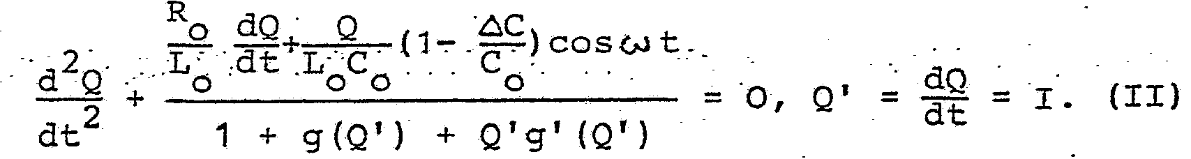
- the invention is based on the knowledge that it is possible to convert the differential equation (I) into an oscillation equation which has sine functions as solutions, namely when the oscillation equation is given a non-linear term.
- the differential equation (II) has a stable sinusoidal solution (after a few periodic non-sinusoidal settling processes), provided that the threshold condition according to the invention applies
- the threshold condition contains the values C o , R o , L o , i.e. the parameter elements of the load-free oscillating circuit, it is considered an inequality even in the loaded state.
- compliance with the threshold condition means that at least as much mechanical energy is supplied to the generator as there are losses in the ohmic resistors.
- compliance with the threshold condition guarantees that the electrical energy supplied is equal to the losses in the ohmic resistances.
- the feature according to the invention according to which at least one parameter element (L, R, C) is a function of the current flowing in the resonant circuit (which leads to non-linearity of the oscillation equation and to sinusoidal solutions) means that an induction coil and / or a resistor is present in the resonant circuit of the machine and / or there must be a capacitor whose inductance or resistance or capacitance changes depending on the current strength.
- At least one induction coil of the inductance of the resonant circuit contains a stationary core made of magnetic material.
- a low-loss ferro-magnetic material for the core of the induction coil, the hysteresis loop of which therefore includes the smallest possible area.
- the Hysteresis curve should be as steep as possible, so that the dependency is very large.
- Another technical possibility of non-linearization of the vibration equation is e.g. in a circuit of a thermal resistor in series with the inductance of the resonant circuit, i.e. a resistor that changes depending on the current (and temperature), or in the use of a capacitor, the capacitance, e.g. due to its special properties, its dielectric depends on the current flowing through it.
- Fig. 2 shows in section an embodiment of a capacitor with time-varying capacitance and an induction coil with an iron core connected in series.
- FIG. 3 shows a rotor plate in view and FIG. 4 shows a stator plate of the capacitor according to FIG. 2.
- FIGS. 5 and 6 show further circuit diagrams of the parametric generator according to the invention.
- the parametric generator consists of a capacitor 1 with a periodically changing capacitance and an induction coil 2 with a core 3 made of ferromagnetic material. 4 with a consumer is designated, which in this case is connected in parallel to the induction coil 2.
- the capacitor 1 consists, as can be seen in FIG. 2, of stator plates 5 and rotor plates 6.
- the rotor plates 6 sit in an electrically conductive connection on the shaft 7, which is driven by a symbolically represented mechanical drive 8, e.g. an engine or a turbine.
- the stator plates 5 are held by electrically conductive rods 9.
- the stator plates 5 and rotor plates 6 are constructed essentially the same and consist, as can be seen from FIGS. 3 (rotor plate) and 4 (stator plate), alternately from sectors 10 made of electrically conductive material, e.g. Copper, and sectors 11 of electrically insulating material, e.g. Plastic. Due to the rotation of the rotor plates 6, the capacitance C of the capacitor changes periodically with time.
- the induction coil 2 connected in series with the capacitor 1 consists of the coil winding 12 and the iron core 3, which in the present case is an EI core, made up of technical dynamo sheets IV of 0.35 mm Thickness and a loss figure (V 10 ) of 1.3 W / kg.
- the consumer, not shown, is connected, for example, to the terminals 13 of the induction coil 2.
- the parametric generator Since the temporal periodicity of the capacitance of the capacitor 1 must correspond to the frequency of the resonant circuit in the sense of the "resonance condition", it is expedient if the parametric generator has setting options in this regard.
- the length of the period of the time change of the capacitance 'of the capacitor 1 depends on the speed of the motor or the turbine, and in the case of the exemplary embodiment shown. - From the number of sectors 10, 11 of the rotor plates 6 or 5 stator plates. To meet the resonance conditions, one can e.g. the speed of the drive 8, for example with the help of a continuously variable transmission, vary.
- the electromagnetic variables of the resonant circuit can also be designed to be adjustable, for example the inductance of the induction coil 2 by adjusting the air gap between the yoke (I-piece) 3 'and the
- E-piece of the iron core 3 or change the total capacity by connecting an additional small variable capacity in series.
- the coil winding 12 of the inductance of the resonant circuit forming the primary winding of the transformer and the iron core 3 of the inductance of the resonant circuit is designed so that it magnetically couples the primary winding 12 and secondary winding 14.
- the entire coil winding 12 of the inductance of the resonant circuit does not necessarily have to be the primary winding of the transformer at the same time part of the induction coils form the primary winding of the transformer.
- the time-periodically changing capacitance can also be solved in a technically different manner than in the exemplary embodiment described, for example by forming the dielectric of the capacitor as a gearwheel and the like, driven by a motor, a water turbine or the like. can rotate between the capacitor plates.
- a cylindrical capacitor which consists of two mutually rotatable, alternately divided into sections of conductive and dielectric material, coaxially pushed cylindrical rollers.
- the capacitor shown in the drawings can (according to general thermodynamic principles) also be used as a motor if one applies an alternating voltage to the terminals 13 in FIG. 2 and gives the rotor plates 6 of the capacitor 1 or the capacitor shaft 7 an initial torque in order to "Resonance condition" to meet. This then results in positive and negative charging of the sectors 10 and in electrostatic repulsive forces or torques.
Abstract
Description


Claims

Priority Applications (14)
| Application Number | Priority Date | Filing Date | Title |
|---|---|---|---|
| AT0905182A AT380358B (en) | 1981-10-29 | 1982-06-07 | PARAMETRIC ELECTRICAL MACHINE |
| GB08314101A GB2116802B (en) | 1981-10-29 | 1982-06-07 | Parametric electric machine |
| IN688/DEL/82A IN158580B (en) | 1981-10-29 | 1982-09-08 | |
| GR69237A GR77350B (en) | 1981-10-29 | 1982-09-08 | |
| IL66842A IL66842A (en) | 1981-10-29 | 1982-09-22 | Parametric electric machine |
| CA000412702A CA1181804A (en) | 1981-10-29 | 1982-10-01 | Parametric electric machine |
| NO823338A NO823338L (en) | 1981-10-29 | 1982-10-04 | PARAMETRIC ELECTRICAL MACHINE. |
| FI823637A FI823637L (en) | 1981-10-29 | 1982-10-25 | PARAMETRISK ELEKTRISK MASKIN |
| AU89759/82A AU8975982A (en) | 1981-10-29 | 1982-10-25 | Parametric resonator |
| EG82637A EG14987A (en) | 1981-10-29 | 1982-10-27 | Parametric electric machine |
| DD82244348A DD208714A5 (en) | 1981-10-29 | 1982-10-28 | PARAMETRIC ELECTRICAL MACHINE |
| ES516919A ES516919A0 (en) | 1981-10-29 | 1982-10-28 | IMPROVEMENTS IN A PARAMETRIC ELECTRIC MACHINE. |
| AR291143A AR230903A1 (en) | 1981-10-29 | 1982-10-28 | IMPROVED PARAMETRIC ELECTRIC MACHINE |
| IT8223981A IT1191054B (en) | 1981-10-29 | 1982-10-28 | PARAMETRIC ELECTRIC MACHINE WITH OSCILLATING CIRCUIT |
Applications Claiming Priority (2)
| Application Number | Priority Date | Filing Date | Title |
|---|---|---|---|
| AT460381 | 1981-10-29 | ||
| ATA4603/81811029 | 1981-10-29 |
Publications (1)
| Publication Number | Publication Date |
|---|---|
| WO1983001713A1 true WO1983001713A1 (en) | 1983-05-11 |
Family
ID=3566059
Family Applications (1)
| Application Number | Title | Priority Date | Filing Date |
|---|---|---|---|
| PCT/AT1982/000018 WO1983001713A1 (en) | 1981-10-29 | 1982-06-07 | Parametric electric machine |
Country Status (21)
| Country | Link |
|---|---|
| US (1) | US4622510A (en) |
| EP (1) | EP0092549A1 (en) |
| JP (1) | JPS58501852A (en) |
| AR (1) | AR230903A1 (en) |
| AT (1) | AT380358B (en) |
| AU (1) | AU8975982A (en) |
| BR (1) | BR8207847A (en) |
| CA (1) | CA1181804A (en) |
| DD (1) | DD208714A5 (en) |
| EG (1) | EG14987A (en) |
| ES (1) | ES516919A0 (en) |
| FI (1) | FI823637L (en) |
| GB (1) | GB2116802B (en) |
| GR (1) | GR77350B (en) |
| HU (1) | HU186149B (en) |
| IL (1) | IL66842A (en) |
| IN (1) | IN158580B (en) |
| IT (1) | IT1191054B (en) |
| NO (1) | NO823338L (en) |
| WO (1) | WO1983001713A1 (en) |
| ZA (1) | ZA827384B (en) |
Families Citing this family (18)
| Publication number | Priority date | Publication date | Assignee | Title |
|---|---|---|---|---|
| US4897592A (en) * | 1988-06-27 | 1990-01-30 | Hyde William W | Electrostatic energy field power generating system |
| DE4033390A1 (en) * | 1990-10-20 | 1992-04-30 | Tralau Guenter Dipl Phys | Electromagnetic energy prodn. from heat content of gas - has assistance of cyclically controlled gas pressure across distance between two capacitor plates and is altered cyclically to produce energy |
| CN1101768A (en) * | 1993-10-14 | 1995-04-19 | 周符明 | Electric energy generating method and electric energy generator for realizing the method |
| DE4418581C2 (en) * | 1994-05-27 | 1995-06-29 | Horst Prof Dr Lippmann | Device for converting the energy of surface waves of a liquid into electrical energy and vice versa |
| US5883499A (en) * | 1996-07-29 | 1999-03-16 | The Regents Of The University Of California | Method for leveling the power output of an electromechanical battery as a function of speed |
| US7034498B2 (en) * | 2002-10-18 | 2006-04-25 | Rt Patent Company, Inc. | Resonant motor system |
| US20060038530A1 (en) * | 2004-07-07 | 2006-02-23 | Rt Patent Company, Inc. | System and method for optimizing motor performance by varying flux |
| US7116029B2 (en) * | 2004-07-19 | 2006-10-03 | Rt Patent Company, Inc. | AC induction motor having multiple poles and increased stator/rotor gap |
| US20060208603A1 (en) * | 2005-03-18 | 2006-09-21 | Rt Patent Company, Inc. | Rotating electric machine with variable length air gap |
| US20070132331A1 (en) * | 2005-12-13 | 2007-06-14 | Rt Patent Company, Inc. | DC homopolar motor/generator |
| US20070132334A1 (en) * | 2005-12-14 | 2007-06-14 | Rt Patent Company, Inc. | Systems and methods for providing electrical contact with a rotating element of a machine |
| GB2436895A (en) * | 2006-04-03 | 2007-10-10 | Rolls Royce Plc | A high voltage current generator using varying capactitance |
| US7834513B2 (en) * | 2007-09-10 | 2010-11-16 | Lawrence Livermore National Security, Llc | Electrostatic generator/motor having rotors of varying thickness and a central stator electrically connected together into two groups |
| US8264121B2 (en) | 2007-09-10 | 2012-09-11 | Lawrence Livermore National Security, Llc | Electrostatic generator/motor configurations |
| US9614462B2 (en) | 2007-09-10 | 2017-04-04 | Lawrence Livermore National Security, Llc | Rippled disc electrostatic generator/motor configurations utilizing magnetic insulation |
| US20100237629A1 (en) * | 2008-01-09 | 2010-09-23 | Velkess, Inc. | Flywheel system |
| US9270204B2 (en) | 2013-06-13 | 2016-02-23 | Lawrence Livermore National Security, Llc | Technique for enhancing the power output of an electrostatic generator employing parametric resonance |
| US10110146B2 (en) | 2014-09-30 | 2018-10-23 | Lawrence Livermore National Security, Llc | Pulse-train drive system for electrostatic generators and motors |
Citations (3)
| Publication number | Priority date | Publication date | Assignee | Title |
|---|---|---|---|---|
| DE348610C (en) * | 1915-03-12 | 1922-02-13 | Plauson S Forschungsinstitut G | Electric motor for alternating current with a high number of periods |
| DE360701C (en) * | 1922-10-06 | Albert Pfeiffer | Influence machine for generating alternating current with static, continuously externally excited surfaces | |
| DE633259C (en) * | 1932-10-29 | 1936-07-23 | Leonid Mandelstam | Arrangement for generating alternating currents |
Family Cites Families (4)
| Publication number | Priority date | Publication date | Assignee | Title |
|---|---|---|---|---|
| US2540327A (en) * | 1948-01-16 | 1951-02-06 | Centre Nat Rech Scient | Electrostatic machine |
| US3094653A (en) * | 1961-05-22 | 1963-06-18 | Tylan Corp | Electrostatic generator |
| US4054826A (en) * | 1975-03-10 | 1977-10-18 | Wahlstrom Sven E | Method and apparatus for charging batteries using variable capacitors |
| US4084101A (en) * | 1975-11-13 | 1978-04-11 | Arden Sher | Apparatus for converting radiant energy to electric energy |
-
1982
- 1982-06-07 EP EP82901826A patent/EP0092549A1/en not_active Withdrawn
- 1982-06-07 GB GB08314101A patent/GB2116802B/en not_active Expired
- 1982-06-07 JP JP82501881A patent/JPS58501852A/en active Pending
- 1982-06-07 AT AT0905182A patent/AT380358B/en not_active IP Right Cessation
- 1982-06-07 US US06/514,816 patent/US4622510A/en not_active Expired - Fee Related
- 1982-06-07 WO PCT/AT1982/000018 patent/WO1983001713A1/en not_active Application Discontinuation
- 1982-09-08 GR GR69237A patent/GR77350B/el unknown
- 1982-09-08 IN IN688/DEL/82A patent/IN158580B/en unknown
- 1982-09-22 IL IL66842A patent/IL66842A/en unknown
- 1982-10-01 CA CA000412702A patent/CA1181804A/en not_active Expired
- 1982-10-04 NO NO823338A patent/NO823338L/en unknown
- 1982-10-08 ZA ZA827384A patent/ZA827384B/en unknown
- 1982-10-25 FI FI823637A patent/FI823637L/en not_active Application Discontinuation
- 1982-10-25 AU AU89759/82A patent/AU8975982A/en not_active Abandoned
- 1982-10-27 HU HU823468A patent/HU186149B/en unknown
- 1982-10-27 EG EG82637A patent/EG14987A/en active
- 1982-10-28 AR AR291143A patent/AR230903A1/en active
- 1982-10-28 IT IT8223981A patent/IT1191054B/en active
- 1982-10-28 DD DD82244348A patent/DD208714A5/en unknown
- 1982-10-28 ES ES516919A patent/ES516919A0/en active Granted
- 1982-10-29 BR BR8207847A patent/BR8207847A/en unknown
Patent Citations (3)
| Publication number | Priority date | Publication date | Assignee | Title |
|---|---|---|---|---|
| DE360701C (en) * | 1922-10-06 | Albert Pfeiffer | Influence machine for generating alternating current with static, continuously externally excited surfaces | |
| DE348610C (en) * | 1915-03-12 | 1922-02-13 | Plauson S Forschungsinstitut G | Electric motor for alternating current with a high number of periods |
| DE633259C (en) * | 1932-10-29 | 1936-07-23 | Leonid Mandelstam | Arrangement for generating alternating currents |
Non-Patent Citations (1)
| Title |
|---|
| Light Metals, November 1946 (Heywood Temple Industrial Publication Ltd. London (GB) B.J. BRENJNIKOFF: "Aluminium and Magnesium in the Electrical Industries", see page 611, left hand column, lines 6-50: page 611, right hand column; page 612, page 613, left hand column, lines 1 to 13, figures 3, 4, 6 * |
Also Published As
| Publication number | Publication date |
|---|---|
| BR8207847A (en) | 1984-08-07 |
| AT380358B (en) | 1986-05-12 |
| AR230903A1 (en) | 1984-07-31 |
| ZA827384B (en) | 1983-08-31 |
| ES8308658A1 (en) | 1983-09-16 |
| IL66842A0 (en) | 1984-05-31 |
| NO823338L (en) | 1983-05-02 |
| EP0092549A1 (en) | 1983-11-02 |
| EG14987A (en) | 1985-03-31 |
| GB2116802A (en) | 1983-09-28 |
| GB2116802B (en) | 1985-04-11 |
| GB8314101D0 (en) | 1983-06-29 |
| AU8975982A (en) | 1983-05-05 |
| US4622510A (en) | 1986-11-11 |
| CA1181804A (en) | 1985-01-29 |
| IL66842A (en) | 1985-10-31 |
| IT8223981A0 (en) | 1982-10-28 |
| DD208714A5 (en) | 1984-04-04 |
| JPS58501852A (en) | 1983-10-27 |
| IT1191054B (en) | 1988-02-24 |
| FI823637L (en) | 1983-04-30 |
| HU186149B (en) | 1985-06-28 |
| ATA905182A (en) | 1985-09-15 |
| ES516919A0 (en) | 1983-09-16 |
| FI823637A0 (en) | 1982-10-25 |
| GR77350B (en) | 1984-09-11 |
| IN158580B (en) | 1986-12-13 |
Similar Documents
| Publication | Publication Date | Title |
|---|---|---|
| WO1983001713A1 (en) | Parametric electric machine | |
| DE2261671A1 (en) | STATOR ARRANGEMENT FOR SINGLE-PHASE INDUCTION MOTOR | |
| DE2305251B2 (en) | EXCITATION DEVICE FOR A SELF-EXCITED ASYNCHRONOUS GENERATOR | |
| CH667168A5 (en) | MULTI-PHASE ELECTRICAL MACHINE WITH CONTROLLED MAGNET FLOW DENSITY. | |
| EP0258344B1 (en) | Electrical component with inductive and capacitive properties | |
| DE2631547B2 (en) | Electric alternating current motor, in particular induction motor with squirrel cage | |
| EP0650248A2 (en) | Power supply | |
| DE102008032666A1 (en) | Capacitive winding for electric motors, transformers and electromagnets | |
| DE2626372A1 (en) | DEVICE FOR SEPARATING ELECTRICALLY CONDUCTIVE COMPONENTS FROM MIXTURES, IN PARTICULAR FROM MUELL | |
| DE3125240A1 (en) | SAME HIGH VOLTAGE GENERATOR | |
| DE2531472A1 (en) | ELECTRIC MACHINE | |
| DE3506651A1 (en) | AC motor | |
| EP0468015B1 (en) | Constant voltage asynchronous generator with stator slot bridges | |
| EP1217712A2 (en) | Damping of amplified resonances at a motor driven with a constant voltage inverter by amplifying losses in the range of critical self oscillations | |
| DE3403041C1 (en) | Single-phase synchronous motor with a two-pole permanent magnetic rotor | |
| DE2634951A1 (en) | Generator producing constant frequency AC for aircraft supply systems - has four active poles and five pole-section groups supplying 400 Hz | |
| DE1814989A1 (en) | Supply device for a stepping motor | |
| DE1277333B (en) | Circuit arrangement for the rapid construction and power-saving maintenance of the magnetic field of coils | |
| DE3316833C2 (en) | DC ring winding for an asynchronous generator | |
| DE3304664A1 (en) | PERFECTED SINGLE-PHASE GENERATOR | |
| DE233970C (en) | ||
| EP0146818A2 (en) | Magnetic amplifier and speed control circuit for motors and its use | |
| EP1489722A1 (en) | Electric motor | |
| DE1538346C (en) | Power supply system for approximately constant frequency | |
| DE252516C (en) |
Legal Events
| Date | Code | Title | Description |
|---|---|---|---|
| AK | Designated states |
Designated state(s): AT DE GB JP US |
|
| AL | Designated countries for regional patents |
Designated state(s): AT BE CH DE FR GB LU NL SE |
|
| WWE | Wipo information: entry into national phase |
Ref document number: 1982901826 Country of ref document: EP |
|
| ENP | Entry into the national phase |
Ref country code: AT Ref document number: 1982 9051 Date of ref document: 19830511 Kind code of ref document: A Format of ref document f/p: F |
|
| WWP | Wipo information: published in national office |
Ref document number: 1982901826 Country of ref document: EP |
|
| WWW | Wipo information: withdrawn in national office |
Ref document number: 1982901826 Country of ref document: EP |