WO2006111401A2 - A technique for platform-independent service modeling - Google Patents

A technique for platform-independent service modeling Download PDF

Info

Publication number
WO2006111401A2
WO2006111401A2 PCT/EP2006/003692 EP2006003692W WO2006111401A2 WO 2006111401 A2 WO2006111401 A2 WO 2006111401A2 EP 2006003692 W EP2006003692 W EP 2006003692W WO 2006111401 A2 WO2006111401 A2 WO 2006111401A2
Authority
WO
WIPO (PCT)
Prior art keywords
service
platform
model
model elements
specific
Prior art date
Application number
PCT/EP2006/003692
Other languages
French (fr)
Other versions
WO2006111401A3 (en
Inventor
Aniello Bove
Hansbeat Loacker
Original Assignee
Ubs Ag
Priority date (The priority date is an assumption and is not a legal conclusion. Google has not performed a legal analysis and makes no representation as to the accuracy of the date listed.)
Filing date
Publication date
Application filed by Ubs Ag filed Critical Ubs Ag
Publication of WO2006111401A2 publication Critical patent/WO2006111401A2/en
Publication of WO2006111401A3 publication Critical patent/WO2006111401A3/en
Priority to HK08107074.6A priority Critical patent/HK1112085A1/en

Links

Classifications

    • GPHYSICS
    • G06COMPUTING; CALCULATING OR COUNTING
    • G06FELECTRIC DIGITAL DATA PROCESSING
    • G06F8/00Arrangements for software engineering
    • G06F8/30Creation or generation of source code
    • G06F8/35Creation or generation of source code model driven
    • GPHYSICS
    • G06COMPUTING; CALCULATING OR COUNTING
    • G06FELECTRIC DIGITAL DATA PROCESSING
    • G06F8/00Arrangements for software engineering
    • G06F8/30Creation or generation of source code
    • G06F8/36Software reuse

Definitions

  • the invention generally relates to the field of generating platform-independent service models. More specifically, the invention relates to the generation of platform- independent service models that form the basis for platform-specific physical artifacts.
  • the software architecture defines different kinds of classes.
  • a first kind a classes may represent persistent entities, while a second kind of classes represents processes or process steps.
  • Whether a specific element of the logical model is an entity or a process is of course a functional issue.
  • the way how a logical entity will eventually be transformed into the corresponding physical representation is generally the same for all logical entities, and the same holds for the transformation of logical processes.
  • Generative software development exploits the fact that the step from a logical model to the physical artifact can be regarded as the application of a set of transformation rules to the various elements of the logical model. So basically one has to define the individual transformations, specify when to apply them and annotate the logical model with some control information that controls the automated transformation process.
  • Transformations are typically defined via templates. For each of the different physical artifacts that need to be generated, a separate template or set of templates will have to be provided.
  • the templates include transformation logic specifying how the individual elements of the logical model are to be transformed into their physical counterparts.
  • the logical model in turn, includes annotations specifying which template to use for a particular type of model element.
  • the annotations are for example constituted by stereotypes or tagged values.
  • a model may include protected sections in which the developer can directly write program code that is to be protected from the transformation run.
  • the protected section guarantees that the manually entered code survives changes in the model. So even if the model is (e.g. iteratively) changed, the code in the protected sections will still remain in the same logical place.
  • the SOA aims at providing the functionalities of a complex software component via individual services.
  • individual services may be used and re-used, rather than copying the corresponding program code or, more generally, the physical artifact. This becomes possible as the service is abstracted away from a particular platform-specific implementation.
  • the object underlying the invention generally relates to an efficient combination of MDD with SOA.
  • a technique for efficiently modeling a service for generative software development is required.
  • a template-driven system for generating platform-specific artifacts, such as program code, from platform-independent service models.
  • the system comprises a template storage with platform-specific templates, each template including platform-specific model transformation information; a repository with a plurality of at least essentially platform-independent service model elements and one or more service models modeled from the model elements; and a generator adapted to generate platform-specific artifacts by applying the transformation information included in the templates to the service models.
  • model elements that constitute the services models may be platform-independent to the largest possible extent, in one variation the model elements may nonetheless be associated with minor platform-specific information.
  • this platform-specific information may include attribute-related format information.
  • At least some of the service model elements may be shared by two or more service models. This re-use of previously defined model elements for a plurality of service models reduces redundant modeling efforts. Moreover, change management is facilitated as changes to an individual model element will automatically be reflected in each service model comprising this model element.
  • the system may further comprise a service model creator for creating at least one of service model elements and platform-independent service models from the service model elements.
  • the output of the service model creator is preferably again stored in the repository.
  • the service model elements included in the repository are hierarchically structured. Such a hierarchical structure facilitates the creation of service models and additionally helps to structure the internal design of the repository.
  • the repository may be configured as a database (e.g. a relational database).
  • each service may be modeled from one or more first model elements of a higher hierarchy level and one or more second model elements of a lower hierarchy level.
  • each first model element may be associated with one or more second model elements.
  • the one or more second model elements preferably constitute attributes of the first model elements.
  • the first model elements may define at least one of one or more service input parameters and one or more service output parameters.
  • the second model elements may constitute leaf fields in at least one of a service input parameter tree and a service output parameter tree.
  • the service models in the repository are associated with mappings.
  • the mappings may occur between two or more model elements or between model elements and database tables.
  • the mappings may define transfer operations between model elements belonging to the same hierarchy level.
  • the mappings define transfer operations between one or more service input parameters and one or more service output parameters.
  • the input parameters and output parameters may belong to one and the same or, alternatively, they may belong to different services.
  • predefined service types and service publicities may be selectable.
  • the service model creator may then allow for a selection of at least one of a service type and a service publicity.
  • the service types preferably include one or more of a process service, an entity service, a presentation service, a technical service, a batch job and a view.
  • the template storage may include at least one dedicated template for each service type. The service type can thus be interpreted as a transformation control parameter.
  • first model elements may be defined and selectable via the service model creator for service modeling.
  • the kinds of first model elements may constitute transformation control parameters when generating the physical artifacts.
  • the generated artifacts may include at least one of Java code, Cobol code, HTML code and XML code.
  • the generator allows for a selection of a platform type.
  • the template storage may include at least one dedicated template.
  • the template storage may include for various combinations of service type and platform type at least one dedicated template.
  • a repository database comprises at least essentially platform-independent model elements and service models modeled from the model elements, the service models forming the basis for the generation of platform-specific artifacts under the control of platform-specific templates, each template including platform-specific model transformation information.
  • a method for generating platform- specific artifacts, such as program code, from platform-independent service models comprises the steps of providing platform-specific templates, each template including platform-specific model transformation information; providing a plurality of at least essentially platform-independent service model elements and one or more service models modeled from the model elements; and generating platform-specific artifacts by applying the transformation information included in the templates to the service models.
  • the invention can be practiced in the form of hardware, in the form of software, or in the form of a combined hardware/software approach.
  • a computer program product is provided.
  • the computer program product comprises program code portions for performing the steps of the present invention when the computer program product is run on one or more computing devices.
  • the computer program product may be stored on a computer-readable recording medium.
  • Fig. 1 is a schematic block diagram illustrating a first device embodiment of the present invention
  • FIG. 2 is a flowchart illustrating a first method embodiment of the present invention
  • Fig. 3 is a schematic block diagram illustrating a second device embodiment of the present invention
  • Fig. 4 is a schematic diagram illustrating the major functionalities of the second device embodiment
  • Fig. 5 is a schematic diagram illustrating an iterative development process used in context with the embodiments and two different service modeling approaches;
  • Fig. 6 is a schematic diagram illustrating the major entities of the logical data model used in the embodiments.
  • Figs. 7 to 9 are schematic diagrams illustrating the individual parts of the logical data model of Fig. 6;
  • Fig. 10 is a flowchart illustrating the decision process relating to two fundamental modeling approaches
  • Fig. 11 is a flowchart illustrating the basic steps of a second method embodiment for generating a service model
  • Fig. 11a is an overview illustrating the definition of various kinds of services as used herein.
  • Figs. 12 to 74 illustrate various user interfaces for use in the second method embodiment.
  • Hg. 1 shows an embodiment of a template-driven system 100 for generating platform-specific artifacts from platform-independent service models.
  • the system 100 comprises three main components: a template storage 102, a repository database 104, and a generator for platform-specific artifacts 106.
  • a template storage 102 In the template storage 102 platform-specific templates are stored.
  • Each template includes platform-specific transformation information.
  • the repository database 104 includes a plurality of at least essentially platform- independent service model elements and one or more service models modeled from the model elements.
  • the model elements included in the repository database are preferably shared by several of the service models. This reduces the overall number of model elements that have to be stored.
  • the generator 106 generates platform-specific artifacts. To this end, one or more of the platform-specific templates included in the template storage 102 are applied to the platform-independent service models stored in the repository database 104.
  • Fig. 2 shows a flowchart 200 illustrating a method embodiment for generating platform-specific artifacts from platform-independent service models. The method may be performed by the system 100 shown in Fig. 1 or any other device.
  • the method starts, in step 202, with the provision of platform-specific templates.
  • Each template includes platform-specific transformation information required for transforming a particular service model into a particular artifact.
  • a plurality of at least essentially platform-independent service model elements are provided. Additionally, one or more service models modeled from the model elements are provided.
  • platform-specific artifacts are generated. For generation of the artifacts, one or more of the platform-specific templates are applied to a particular platform-independent service model.
  • Fig. 3 shows a further system 300 for generating artifacts from platform-independent service models.
  • the system 300 includes a repository database 302 for service models (and service model elements) and a template-driven generator 304 for generating artifacts 308 for the service models stored in the repository database 302.
  • the transformation of service models to artifacts is controlled by template files 306.
  • template files 306 In the present embodiment, for each individual platform a specific set of one or more template files 306 is provided. If needed, the generated artifacts may manually be completed (e.g. within so-called protected areas) before storing them in a software component management repository 310.
  • Fig. 4 schematically shows the way of a platform-independent model to a platform- specific artifact as implemented in the systems 100 and 300 discussed above.
  • a platform-independent service model is generated first.
  • the platform-independent service model is then transformed into a platform-specific artifact such as an executable presentation or application (business) service.
  • Fig. 5 illustrates, on the left-hand side, the iterative generation of a service starting from a service model.
  • the two basic approaches for generating a physical artifact are shown, namely the top-down approach on the one hand and the bottom-up approach on the other hand. These approaches will later be described in more detail with reference to the user interfaces of Figs. 12 to 74.
  • the main elements of the logical data model used in the present embodiments are shown in Fig. 6.
  • the logical data model provides the basis for the physical database design of the repository database 302. It is independent of the implementation and thus makes a clear distinction between specification and implementation on the database. Its physical model is more complex and contains many more elements, which are relevant to store all detailed information about each of the main elements. Nevertheless, the logical data model as shown in Fig. 6 is the key to the overall repository database.
  • One service is modeled from two basic and hierarchically structured model elements, complex type model elements (or simply "complex types"), which may again comprise complex types, on the one hand and data item model elements (or simply "data items”) on the other hand. These model elements are shown in Fig. 7.
  • the relationship between a service and these two model element categories is represented via a field element as shown in Fig. 8.
  • the field element is an instance of an individual data item and manages the relationship and usage of data items within complex types.
  • the relationship between individual services is represented via a mapping element as depicted in Fig. 9.
  • Figs. 10 to 74 the tool permits two ways of service modeling.
  • the top-down implementation shown on the left hand side of Fig. 10 is used in the case that no specific artifacts are available for reuse ("green field modeling").
  • the bottom-up implementation shown on the right hand side of Fig. 10 has some prerequisites, some physical implementations (such as a database table description, source code, ..) that will be reused for service design ("modeling based on physical artifact").
  • the meta model will be the same in each case.
  • the service for which the service model is to be created may for example be the mutation of a customer address in a database or the search for customers in the database that fulfill certain criteria.
  • the software developer Before starting the modeling of a service, the software developer has to think about the interfaces of the service to be modeled, i.e. the input and output parameters, as well as how the input parameters are transferred ("mapped") to the output parameters.
  • step 1 of Fig. 11 the initiation of a new service model for a particular software component (that may include further services) starts with the display of a graphical user interface as shown in Fig. 12.
  • the user interface of Fig. 12 requests the input of service parameters as illustrated in the following table:
  • Fig. 11a schematically illustrates in a layered manner some of the various service types that can be selected.
  • Presentation services reside on an upper layer. This service type mainly provide visual functionalities in context with requesting information from a user and/or displaying information to a user.
  • database services are provided on a lower layer.
  • a middle layer provides general application services that are neither presentation services nor database services (sometimes also called business services herein).
  • Entity services generally have database access (e.g. they read data from a database or write data into a database using the corresponding database service).
  • Process services on the other hand, have no (direct) database access. They perform one or more dedicated processing operations and include the application logic required for this task.
  • the selection of a particular service type via the user interface of Fig. 12 influences the template (or template set) that will later be used when transforming the corresponding service model into a particular artifact.
  • there will be one or more dedicated templates for presentation services (specifying, for example, the visual appearance of the resulting graphical user interface), one or more dedicated templates for entity services (specifying, for example, the database interfaces), and so on.
  • Each publicity category in the above table indicates the availability of the service model (or its elements) for re-use a hierarchical software environment that includes, from a lower hierarchy level to a higher hierarchy level, the levels "Software
  • a service always belongs to a particular software component, which means that service governance is performed via the associated software component.
  • Each software component has an owner, which is at the same time the owner of all the services assigned to this software component.
  • software components such as application components for the backend, presentation components for the front-end, and technical components for technical purposes.
  • a presentation service can only exist within a presentation component, an application service can only exist within an application component, and so on.
  • the type of a particular software component controls the service types that may be associated therewith.
  • a presentation service may for example not exist within an application component.
  • a presentation service always requires at least one application service for performing an operation within the backend (e.g. a backend processing operation or a database operation). The reason for this is the fact that presentation services are not allowed to access databases or include backend processing logic. These tasks are always performed by application/business services.
  • Fig. 13 shows the user interface that allows for an editing of the "basic data" of a service that is to be newiy generated.
  • Implementation-specific attributes can be defined via the tab "Attributes" in the lower left corner of the user interface shown in Fig. 14.
  • the "Attributes" user interface is illustrated in Fig. 15. It should be noted that although the service modeling is to a large extent implementation-independent, it might nonetheless be advantageous to specify a small amount of implementation-specific information already when modeling the service.
  • each service necessarily includes one or more complex types, and each complex type may in turn include one or more further complex types.
  • Fig. 16 shows the complex type "aku" of the sequence kind.
  • This kind of complex type consists of a sequence of individual fields (see Fig. 8), here titled “Address- Element_l” to "Address_Element_4", as shown in the following table:
  • Fig. 17 shows the complex type "Address_Output" of the list kind.
  • This kind of complex type consists of one or more complex types of the sequence kind (including the complex type "Address” explained above) and additionally of individual fields (including a list length parameter) as shown in the following table:
  • Fig. 18 shows the complex type "Choice” of the choice kind.
  • This kind of complex type typically consists of two or more complex types of the sequence kind (including the complex type "Address” explained above) as shown in the following table:
  • a service model may re-use an existing complex type, in other cases a new complex type has to be created.
  • the required complex type may simply be selected from the previously defined complex types included in the repository database. Re-use of a previously defined complex type may be prevented by an incompatible publicity.
  • Creation of new complex type will now be discussed in context with the user interfaces shown in Figs. 19 to 27.
  • Creation of a new complex type starts with the user interface of Fig. 19. This user interface requests the user to specify the name of the complex type that is to be newly created and the software component to which the complex type is to be assigned. Once the corresponding data have been input, they may be saved by clicking the "OK" button.
  • the newly created complex type may be edited via the user interface shown in Fig. 20.
  • This user interface allows for a selection of the kind of complex type (i.e., either sequence, list or choice as discussed above).
  • the user interface of Fig. 20 basically permits the creation of input or output fields via the menu shown in Fig. 21.
  • creation of a "sibling” creates an element on the same level
  • creation of a "child” creates a child to an element.
  • a leaf attribute, based on a data item type can not have any children.
  • the user interface of Fig. 22 constitutes a data item selection dialog that allows for a re-use of an existing data item included in the repository database. All currently loaded data items are shown in the lower part of the user interface in Fig. 21. If the required data item is not yet shown, a search for this data item can be initiated based on search criteria that may be specified in the upper part of the user interface of Fig. 22. Once the data item that is to be inserted in the newly created complex type is selected and the button "OK" is clicked, a new field for the complex type based on the selected data item is created. In this context the user interface of Fig. 23 will be displayed and an appropriate name for this field can be entered.
  • the user interface of Fig. 24 is displayed.
  • the user interface of Fig. 24 constitutes a complex type selection dialog. All currently loaded complex types are displayed in the result list in the lower part of the user interface of Fig. 24. If the required complex type is not yet displayed, a search can be initiated based on search criteria that may be specified in the upper part of the user interface of Fig. 24. Once the complex type that is to be inserted in the newly created complex type is selected and the button "OK" is clicked, a new field based on the selected complex type is created as shown in Rg. 25.
  • the user interface of Fig. 26 is displayed for creation of a new complex type.
  • the new complex type may be given a characteristic name and the parameter "Kind” is preset to "Sequence” (see Fig. 27).
  • the parameter "Kind” will be preset to "Choice” if the user selects the option "New Choice Complex Type” in the user interface of Fig. 21.
  • the modeling tool of the present embodiment not only allows for a creation of a new complex type, but also for the creation of a new data item (that will then also be stored in the repository database).
  • data items are primarily used for the definition of service parameters. Every leaf in the input or output tree of a service will be based on a data item.
  • existing data items should be reused as often as possible (as explained with reference to Figs. 21 to 23). However, there may still be situations in which the creation of new data items is unavoidable.
  • a new data item will always be a specific data item, meaning that it is created in a specific domain, but with its significance and use by other domains it may become a core data item.
  • Core data items represent the company's main data dictionary.
  • Fig. 28 shows a user interface that allows for the definition of data item properties for a data item that is to be newly created.
  • the properties include a name, description, length, category, a parent and software component.
  • data items must always belong to a particular software component.
  • the initial properties are explained in more detail in the following table:
  • the "OK" button of the user interface of Fig. 28 may be clicked to create the date item.
  • the data item may later be edited via the data items properties user interface shown in Fig. 29.
  • This user interface has five tabs, namely "Basic”, “Physical”, “Business”, “GUI” and “Lifecycle” as shown in Figs. 29, 30, 31, 32 and 33, respectively.
  • the "Physical" properties as shown in Fig. 30 allow for a specification of some implementation-specific information already on the model level in relation to the data item newly created.
  • the physical properties that may be specified include the following:
  • the "Business” (or application) properties as shown in Rg. 31 include the following:
  • GUI The "GUI” properties as shown in Fig. 32 are used to control the presentation of data items in the respective user interfaces. Care will be taken that data items are always shown to the user in the same way and with the same labeling.
  • the "GUI” properties include the following:
  • the "Lifecycle” properties as shown in Fig. 33 reflect the current state of the particular data item ("DI"). These properties are primarily used for data item reviews. Most of the settings can only be set and changed by a user having the corresponding authorization (“Data Manager”).
  • the “Lifecycle” properties include the following:
  • Input and output parameters of a service are composite tree structures (in the form of "complex types"). They are displayed in the modeling tool in a similar manner like folder structures in a file system. That is, complex types correspond to folders, while fields (or attributes) correspond to files. Every field must be assigned to a data item.
  • the modeling tool permits the specification of input and output parameters (i.e. the creation of attributes) either via a tree editor (step 2a in Fig. 11) or, alternatively, via a graphical editor (step 2b in Fig. 11).
  • a tree editor i.e. the creation of attributes
  • a graphical editor step 2b in Fig. 11
  • the tree editor will be discussed first with reference to the user interfaces shown in Figs. 34 to 36. Opening a service and successively selecting the "Interface” (see Fig. 14) and the "Tree” tabs opens the editor for input and output parameters shown in Fig. 34.
  • the pull-down menu in the upper part allows for a switching between "Input” and "Output”.
  • the respective structure of the input or output complex type is shown in the left frame. In the right frame, the properties of the selected field can be described. Right-clicking of an element in the complex type shown in the left frame creates new input or output fields (Fig. 35).
  • Inserting a sibling creates an element on the same level; inserting a child creates a child to an element.
  • a leaf attribute based on a data item type, can, of course, not have any children.
  • Fig. 36 shows an example of an "Input" complex type with an element of the "choice” complex type as displayed by the tree editor.
  • Fig. 37 Opening a service and successively selecting the "Interface" (see Fig. 14) and the "Graphical" tabs opens the graphical editor for input and output parameters shown in Fig. 37.
  • input and output parameters are shown in parallel in their respective hierarchical structure. Different kinds of complex types may graphically be represented in different colors.
  • the toolkit on the left side of Fig. 37 allows for a change of the interface with the following options:
  • mappings can be used as input and output parameters (or parameter sets) of a service.
  • Mappings (step 3 in Fig. 11) now define how a complex type is transferred into another complex type and are thus primarily used for mapping the input parameters of a specific service to its output parameters as illustrated in Fig. 38 for two exemplary complex types.
  • Mapping an input to an output complex type of a service means that one specifies the "algorithm" of the service. It also means that the output can directly be calculated from the input, without calling another service.
  • Mappings are also used for mapping the input parameters of a specific service to database tables or for mapping output parameters of a first service to input parameters of a second service.
  • mappings are defined on a "Mappings" page of the service editor.
  • mappings In order to be handled correctly by the subsequent artifact generator, mappings have to adhere to certain naming conventions, depending on the mapping type. For each mapping a developer can define a name. There are no technical restrictions on these names, but special characters should be avoided as the names will also be used as names in the generated code. If there is more than one mapping in a particular entity service, the same name should be used for all the mappings. In process services, the same name should be used for two substep mappings. In order to create a new mapping, the "Add" button in the "Mappings" page (see Fig. 39) of the service editor has to be clicked.
  • the "Mappings” page can be reached via the "Mappings” tab of the user interface shown in Fig. 14.
  • the main properties of the mapping can be defined by selecting a mapping type via a window as illustrated in Fig. 40.
  • the mapping kind influences the generation of the service code frame (the "construct” that can be manually completed if required). It does not influence the functionalities of the service editor (such as mapping source, mapping target, mapping operation).
  • mappings Input, Output, Restriction, Substep Input (Invoke or Call), Substep Output and Internal Mapping.
  • the properties of these mapping kinds are summarized in the following table:
  • mappings may also be used as a vehicle for transferring data between two individual services.
  • An exemplary scenario is illustrated in Fig. 41.
  • the example shows how the service “GetItemList_Vl_O" (A) is called within the service “GetSingleKunde_Vl_0" (B).
  • a first mapping is used for calling service "B”
  • a second mapping is used for returning the result of service "B” to service "A”.
  • a corresponding user interface is shown in Fig. 42.
  • the input complex type of service "A” is mapped to the input complex type of service "B” in order to provide the necessary information to service "B”.
  • the output complex type of service "B” is mapped to the output complex type of service "A”. This means that the return parameters from the called service "B” are transferred to the output parameters of "A” (see Fig. 43).
  • Mapping sources and mapping targets can either be chosen manually or via the "Use Service” button of the user interface shown in Figs. 39, 42 and 43. Then, a search dialog appears that permits the selection of a service as a substep. After the selection has been confirmed, the mapping sources and mapping targets are offered as shown in the user interface of Fig. 44. This user interface offers the following options:
  • mapping operations In addition to defining mapping sources and mapping targets, mapping operations have to be defined.
  • a mapping operation defines how individual input fields are transferred to the output fields.
  • Fig. 45 shows a user interface in which the copy operation is illustrated. Such an operation is for example useful for transferring data between a database, via one or more entity services and/or process services, and a presentation service.
  • a mapping may be added to a service by clicking one field in the mapping source section, one field in the mapping target section, and by activating the "Add" button. If required, more complex operations could be defined as well.
  • the modeling tool additionally permits error messages management for a service that is to be modeled.
  • Error messages management (step 4 in Fig. 11) will now be explained in more detail with reference to the user interfaces of Figs. 46 to 52.
  • the "Error Messages" page (shown in Fig. 46) can be reached via the corresponding "Error Messages" tab. Error messages already defined for the particular service are displayed automatically in the table "Associated user error messages".
  • the user interface of Fig. 46 shows the page before any messages have been associated with the exemplary (business) service GetAddressinglmageList.
  • Subcomponent-specific messages can be associated with the service by clicking the button "GAC messages", where ⁇ GAC> is the software subcomponent ID in which the services is defined.
  • Common messages can be associated with the service by clicking the button "Common messages". Clicking on either of these two buttons results in a dialog user interface as shown in Fig. 47.
  • the table on the left hand side of the dialog user interface shows all possible messages associated with the subcomponent (or, in the "Common messages" scenario, of Common messages). Selecting a row of the table displays a summary of the message on the right hand side of the dialog. It is possible that the user interface displays no messages, and instead displays an empty table indicating that no error messages have been defined for the subcomponent in question.
  • Fig. 48 shows the original editor screen after both subcomponent-specific and common messages have been added.
  • the user interface as shown in Fig. 48 offers to indicated a "Message Severity". For each message, one of the following options may be selected: "Warning", "Exception” or "Severe"
  • a service may call additional services. These calls are defined in the "Mappings" tab of the service editor. After creating a service mappings, one may reopen the services that are to be called. In the tab “Mapping”, all error messages of the called services are listed. The modeling tool offers the possibility of mapping these "child” error messages into any existing error message which belongs to the service in work as shown in Fig. 49. In this context, one or more child messages may be selected first, and then the option "Map to" may be chosen and one error message can be selected out of the list as shown in Fig. 50. The child messages will be mapped to the selected message. After this action, the corresponding information will be displayed in the column “Mapped to" as shown in Fig. 51. On the tab “ErrorMessages", all messages which map child messages are marked with a check-mark (see Fig. 52). Additionally, a mechanism is provided for removing mappings.
  • the corresponding output code can look as follows:
  • top-down modeling is finished and the service model can be transferred to the generator for generating the required artifacts.
  • bottom-up modeling can be used (see Figs. 5 and 10).
  • This modeling type uses some previously defined artifacts to ensure automated fill-out of repository meta information.
  • the automated processes are called wizards.
  • the following wizards are defined for the modeling tool of the present embodiment: Wizard Name Description
  • a presentation component In order to create a presentation service from a backend application (business application or technical application), a presentation component must be created first.
  • the modeling tool can create a presentation service (e.g. WPS) out of an existing application service.
  • the application service has to be selected first.
  • a container i.e. the software subcomponent for the presentation service, has to be chosen.
  • the user interface of Fig. 53 shows the search function provided by the modeling tool in this regard. Because only business applications and technical applications are allowed here, these kinds of software components are set automatically.
  • the user interface of Fig. 53 permits a search for the desired software component. By clicking 1 OK 1 a software component can be selected and assigned as a container for the presentation service.
  • the presentation service type has to be selected next via the user interface of Fig. 54.
  • the default presentation service type is "Simple”.
  • the version of the presentation service may additionally be entered.
  • a confirmation dialog user interface as shown in Fig. 55 will be displayed.
  • additional steps will have to be initiate that will not be discussed in more detail here. Clicking the "Finish” button initiates the creation of the requested presentation service.
  • elements are created for the presentation service in the repository database of the modeling tool and the presentation service appears in the software component explorer under the selected application and software subcomponent as shown in Fig. 56.
  • the numeral (1) denotes a presentation service created following the instructions for simple presentation service
  • (2) denotes a presentation service created following the instructions for a "modify" presentation service.
  • a further wizard is defined to import a database table and create an entity service.
  • a so-called DCLGEN file can be generated containing a description of the table and a mapping to a Cobol copybook. This file can be used for an import of the table definition in the modeling tool.
  • the DB2 table is represented in the modeling tool as a complex type. Creation of this complex type out of a DCLGEN file starts with a table selection dialog as shown in Fig. 57.
  • the directory of DCLGen-Files should already contain the correct path, e.g.
  • the one or more created complex types can be selected for the creation of an entity service (see Fig. Ha).
  • the entity service for the selected complex types can be defined via the user interface shown in Fig. 58. The following options exist:
  • Entity Service Type Type of Entity Service (Read , . Search etc) . Read (' Get”) of an object
  • the software component release and the subcomponent in which the entity service will be created can be selected via the user interface shown in Fig. 62.
  • the release can be opened by use of the "Search” button (if it is not already open). Clicking "Create” will create the entity service in the selected software subcomponent as shown in Fig. 63. If the newly created entity service is opened and the "Mapping" page is displayed, the two mappings are defined as shown in Figs. 64 and 65.
  • a software component release must first be opened in the software component explorer of the modeling tool. Then the software subcomponent which should provide the service(s) to be created (service provider) is to be selected.
  • the user interface shown in Fig. 66 allows for a selection of one or more input files containing the existing DTD(s). After the selection has been performed, clicking on the "Next" button initiates parsing or the selected DTDs.
  • the complex types that will be created are then displayed next via a user interface shown in Fig. 67.
  • the import mechanism merges all complex types that are equivalent. Clicking on the "Finish" button starts the import process.
  • a software component release must be opened in the software component explorer. Then the software subcomponent which should provide the service(s) to be created (service provider) has to be selected.
  • the import of a Cobol copybook file can be performed via the user interface shown in Fig. 69. This user interface offers the following options.
  • a file has to be selected (extension is ".cpy” or “.cob") via the user interface of Fig. 70.
  • extension is ".cpy” or ".cob"
  • the "Import Definition” might look as shown in Fig. 71. Closing this dialog with "OK” will show this particular import as one row in the copybook import dialog (see Fig. 72).
  • the next task is to assign a data item to every field in the copybooks (by default, all data items are assigned to the "Generic Data Item"). If one or more fields are to be assigned to an existing data item, corresponding steps can be initiated via the "Link selected item(s) to existing Data Items" button, which launches the data item selection dialog. If a new data item is to be created for one or more fields, this can be initiated via the corresponding button of the user interface of Fig. 73. After finishing these assignments, clicking "Finish” will complete the operation and also complete bottom-up generation of the service model.
  • the service model and its individual model elements will at least temporarily be stored in the repository database 302 of the system shown in Fig. 3. If a particular artifact is needed, the service model may then at any time be retrieved from the repository database 302 by the generator 304. The generator will then select one or more template files 306 associated with the underlying service type and with the requested artifact type (e.g. Java code) and transform the service model into an artifact under control of the selected template files 306. Accordingly, one and the same model may form the basis for generating different types of artifacts, including code, test cases, and specifications such as a physical description of a service. For each of these types of artifacts, one or more dedicated template files 306 are provided.
  • the underlying service type e.g. Java code
  • the generated artifacts may be constructs (or frames) that will have to be manually completed by entering code (e.g. specific application logic) within protected areas of the construct.
  • code e.g. specific application logic
  • Such a modeling approach has the advantage that the service model as such is independent of the application logic, which greatly facilitates the re-use of the service model and its model elements. Moreover, amendments to the application logic do not require changes of the underlying service model.
  • the provision of the central repository database permits a guided and highly structured creation of service models. It is ensured that previously defined model elements such as complex types and data items can be shared between software developers and software development projects. This sharing increases the re-use of available model elements and thus reduces redundancies in the modeling process.
  • the central repository database may include more than 5.000 services, more than 25.000 complex types, and more than 5.000 data items. From these numbers the advantages of a central repository becomes apparent.
  • the management of service models and model elements in the repository is much easier (and less resource- consuming) than the management of the corresponding physical artifacts.
  • each element (service, complex type, data item) in the repository may be associated with a unique identifier. The identifier facilitates change management and allows for an (automatic) change modification.
  • Each repository element may additionally be associated with a (re-)use indicator. This indicator may serve for repository management, for example with respect to the deletion and/or archiving of elements that have not been used for a certain period of time.
  • authorization profiles may be defined indicating the (re-)usage rights of individual software developers.

Abstract

A template-driven system for generating platform-specific artifacts, such as program code, from platform-independent service models is described. The system comprises a template storage (102) with platform-specific templates, each template including platform-specific model transformation information; a repository (104) with a plurality of at least essentially platform-independent service model elements and one or more service models modeled from the model elements; and a generator (106) adapted to generate platform-specific artifacts by applying the transformation information included in the templates to the service models.

Description

A Technique for Platform-Independent Service Modeling
Field of the Invention
The invention generally relates to the field of generating platform-independent service models. More specifically, the invention relates to the generation of platform- independent service models that form the basis for platform-specific physical artifacts.
Background of the Invention
Software development conventionally starts with the creation of a logical model reflecting the functional requirements of the particular process for which the software is to be developed. At some point of this model-driven approach, the logical model has to be transformed into a physical representation or artifact (such as a code representation) that additionally satisfies non-functional requirements. Among the non-functional requirements are the technical constraints of the particular software and hardware platform, including the programming language, that have to be taken into account.
For generating the physical code, a set of rules and patterns will have to be applied to the logical model. For example, in some cases, the software architecture defines different kinds of classes. A first kind a classes may represent persistent entities, while a second kind of classes represents processes or process steps. Whether a specific element of the logical model is an entity or a process is of course a functional issue. However, the way how a logical entity will eventually be transformed into the corresponding physical representation is generally the same for all logical entities, and the same holds for the transformation of logical processes.
To assist a software developer in his work and to automate as many steps as possible in the software development process, generative software development approaches have been introduced. Generative software development exploits the fact that the step from a logical model to the physical artifact can be regarded as the application of a set of transformation rules to the various elements of the logical model. So basically one has to define the individual transformations, specify when to apply them and annotate the logical model with some control information that controls the automated transformation process.
Transformations are typically defined via templates. For each of the different physical artifacts that need to be generated, a separate template or set of templates will have to be provided. The templates include transformation logic specifying how the individual elements of the logical model are to be transformed into their physical counterparts. The logical model, in turn, includes annotations specifying which template to use for a particular type of model element. In an conventional UML (Unified Modeling Language) scenario, the annotations are for example constituted by stereotypes or tagged values.
Since not everything can be defined in the model, certain procedural aspects can be defined by programming inside the generated physical constructs. Therefore, a model may include protected sections in which the developer can directly write program code that is to be protected from the transformation run. The protected section guarantees that the manually entered code survives changes in the model. So even if the model is (e.g. iteratively) changed, the code in the protected sections will still remain in the same logical place.
Today, there are attempts to apply the concept of model-driven development (MDD) to the service paradigm underlying the so-called service-oriented architecture (SOA). The SOA aims at providing the functionalities of a complex software component via individual services. In the SOA context, individual services may be used and re-used, rather than copying the corresponding program code or, more generally, the physical artifact. This becomes possible as the service is abstracted away from a particular platform-specific implementation.
In conventional SOAs the individual services are merely regarded as "black boxes" with interfaces to other services. In other words, the internal structure of the services does not play a major role for the implementation of a SOA. However, when applying the principles of MDD to the modeling of individual services, the internal structure of the service model is of course an important aspect.
Therefore, the object underlying the invention generally relates to an efficient combination of MDD with SOA. In particular, a technique for efficiently modeling a service for generative software development is required. Summary of the Invention
According to a first aspect, a template-driven system for generating platform-specific artifacts, such as program code, from platform-independent service models is provided. The system comprises a template storage with platform-specific templates, each template including platform-specific model transformation information; a repository with a plurality of at least essentially platform-independent service model elements and one or more service models modeled from the model elements; and a generator adapted to generate platform-specific artifacts by applying the transformation information included in the templates to the service models.
Although the service models and the model elements that constitute the services models may be platform-independent to the largest possible extent, in one variation the model elements may nonetheless be associated with minor platform-specific information. For model elements that correspond for example to attributes, this platform-specific information may include attribute-related format information.
At least some of the service model elements may be shared by two or more service models. This re-use of previously defined model elements for a plurality of service models reduces redundant modeling efforts. Moreover, change management is facilitated as changes to an individual model element will automatically be reflected in each service model comprising this model element.
The system may further comprise a service model creator for creating at least one of service model elements and platform-independent service models from the service model elements. The output of the service model creator is preferably again stored in the repository.
In one variation, the service model elements included in the repository are hierarchically structured. Such a hierarchical structure facilitates the creation of service models and additionally helps to structure the internal design of the repository. The repository may be configured as a database (e.g. a relational database).
Based on the hierarchical structured model elements, each service may be modeled from one or more first model elements of a higher hierarchy level and one or more second model elements of a lower hierarchy level. In the service model, each first model element may be associated with one or more second model elements. In such a case, the one or more second model elements preferably constitute attributes of the first model elements.
The first model elements may define at least one of one or more service input parameters and one or more service output parameters. On the other hand, the second model elements may constitute leaf fields in at least one of a service input parameter tree and a service output parameter tree.
In a further variation, the service models in the repository are associated with mappings. The mappings may occur between two or more model elements or between model elements and database tables. The mappings may define transfer operations between model elements belonging to the same hierarchy level. In one implementation, the mappings define transfer operations between one or more service input parameters and one or more service output parameters. The input parameters and output parameters may belong to one and the same or, alternatively, they may belong to different services.
For service modeling, predefined service types and service publicities may be selectable. The service model creator may then allow for a selection of at least one of a service type and a service publicity. The service types preferably include one or more of a process service, an entity service, a presentation service, a technical service, a batch job and a view. In such a scenario, the template storage may include at least one dedicated template for each service type. The service type can thus be interpreted as a transformation control parameter.
Additionally, specific kinds of first model elements may be defined and selectable via the service model creator for service modeling. The kinds of first model elements may constitute transformation control parameters when generating the physical artifacts. The generated artifacts may include at least one of Java code, Cobol code, HTML code and XML code.
There may exist a plurality of predefined platform types defining the physical implementation of a particular service model. Preferably, the generator allows for a selection of a platform type. For each platform type, the template storage may include at least one dedicated template. Moreover, the template storage may include for various combinations of service type and platform type at least one dedicated template.
According to a further aspect of the invention, a repository database is provided. The repository database comprises at least essentially platform-independent model elements and service models modeled from the model elements, the service models forming the basis for the generation of platform-specific artifacts under the control of platform-specific templates, each template including platform-specific model transformation information.
According to a still further aspect of the invention, a method for generating platform- specific artifacts, such as program code, from platform-independent service models is provided. The method comprises the steps of providing platform-specific templates, each template including platform-specific model transformation information; providing a plurality of at least essentially platform-independent service model elements and one or more service models modeled from the model elements; and generating platform-specific artifacts by applying the transformation information included in the templates to the service models.
The invention can be practiced in the form of hardware, in the form of software, or in the form of a combined hardware/software approach. As for a software aspect, a computer program product is provided. The computer program product comprises program code portions for performing the steps of the present invention when the computer program product is run on one or more computing devices. The computer program product may be stored on a computer-readable recording medium.
Brief Description of the Drawings
In the following, the invention will be described with reference to exemplary embodiments illustrated in the drawings, wherein:
Fig. 1 is a schematic block diagram illustrating a first device embodiment of the present invention;
Fig. 2 is a flowchart illustrating a first method embodiment of the present invention; Fig. 3 is a schematic block diagram illustrating a second device embodiment of the present invention;
Fig. 4 is a schematic diagram illustrating the major functionalities of the second device embodiment;
Fig. 5 is a schematic diagram illustrating an iterative development process used in context with the embodiments and two different service modeling approaches;
Fig. 6 is a schematic diagram illustrating the major entities of the logical data model used in the embodiments;
Figs. 7 to 9 are schematic diagrams illustrating the individual parts of the logical data model of Fig. 6;
Fig. 10 is a flowchart illustrating the decision process relating to two fundamental modeling approaches;
Fig. 11 is a flowchart illustrating the basic steps of a second method embodiment for generating a service model;
Fig. 11a is an overview illustrating the definition of various kinds of services as used herein; and
Figs. 12 to 74 illustrate various user interfaces for use in the second method embodiment.
Description of Preferred Embodiments
In the following description, for purposes of explanation and not limitation, specific details are set forth, such as particular sequences of steps, user interfaces and device configurations in order to provide a thorough understanding of the present invention. It will be apparent to one skilled in the art that the present invention may be practiced in other embodiments that depart from these specific details.
Moreover, those skilled in the art will appreciate that the functions explained herein below may be implemented using software functioning in conjunction with a programmed microprocessor or general purpose computer. It will also be appreciated that while the current invention is primarily described in the form of methods and devices, the invention may also be embodied in a computer program product as well as in a system comprising a computer processor and memory coupled to the processor, wherein the memory is encoded with one or more programs that may perform the functions disclosed herein.
Hg. 1 shows an embodiment of a template-driven system 100 for generating platform-specific artifacts from platform-independent service models. The system 100 comprises three main components: a template storage 102, a repository database 104, and a generator for platform-specific artifacts 106. In the template storage 102 platform-specific templates are stored. Each template includes platform-specific transformation information.
The repository database 104 includes a plurality of at least essentially platform- independent service model elements and one or more service models modeled from the model elements. The model elements included in the repository database are preferably shared by several of the service models. This reduces the overall number of model elements that have to be stored.
The generator 106 generates platform-specific artifacts. To this end, one or more of the platform-specific templates included in the template storage 102 are applied to the platform-independent service models stored in the repository database 104.
Fig. 2 shows a flowchart 200 illustrating a method embodiment for generating platform-specific artifacts from platform-independent service models. The method may be performed by the system 100 shown in Fig. 1 or any other device.
The method starts, in step 202, with the provision of platform-specific templates. Each template includes platform-specific transformation information required for transforming a particular service model into a particular artifact.
In a next step 204 a plurality of at least essentially platform-independent service model elements are provided. Additionally, one or more service models modeled from the model elements are provided. In a further step 206, platform-specific artifacts are generated. For generation of the artifacts, one or more of the platform-specific templates are applied to a particular platform-independent service model.
Fig. 3 shows a further system 300 for generating artifacts from platform-independent service models. The system 300 includes a repository database 302 for service models (and service model elements) and a template-driven generator 304 for generating artifacts 308 for the service models stored in the repository database 302. The transformation of service models to artifacts is controlled by template files 306. In the present embodiment, for each individual platform a specific set of one or more template files 306 is provided. If needed, the generated artifacts may manually be completed (e.g. within so-called protected areas) before storing them in a software component management repository 310.
Fig. 4 schematically shows the way of a platform-independent model to a platform- specific artifact as implemented in the systems 100 and 300 discussed above. Starting with a platform-independent component model, a platform-independent service model is generated first. The platform-independent service model is then transformed into a platform-specific artifact such as an executable presentation or application (business) service.
Fig. 5 illustrates, on the left-hand side, the iterative generation of a service starting from a service model. On the right-hand side, the two basic approaches for generating a physical artifact are shown, namely the top-down approach on the one hand and the bottom-up approach on the other hand. These approaches will later be described in more detail with reference to the user interfaces of Figs. 12 to 74.
The main elements of the logical data model used in the present embodiments are shown in Fig. 6. The logical data model provides the basis for the physical database design of the repository database 302. It is independent of the implementation and thus makes a clear distinction between specification and implementation on the database. Its physical model is more complex and contains many more elements, which are relevant to store all detailed information about each of the main elements. Nevertheless, the logical data model as shown in Fig. 6 is the key to the overall repository database. One service is modeled from two basic and hierarchically structured model elements, complex type model elements (or simply "complex types"), which may again comprise complex types, on the one hand and data item model elements (or simply "data items") on the other hand. These model elements are shown in Fig. 7. The relationship between a service and these two model element categories is represented via a field element as shown in Fig. 8. The field element is an instance of an individual data item and manages the relationship and usage of data items within complex types. The relationship between individual services is represented via a mapping element as depicted in Fig. 9.
In the following a tool for generating service models for a particular software component will be discussed with reference to Figs. 10 to 74. As shown in Fig. 10, and as already mentioned in context with Fig. 5, the tool permits two ways of service modeling. The top-down implementation shown on the left hand side of Fig. 10 is used in the case that no specific artifacts are available for reuse ("green field modeling"). The bottom-up implementation shown on the right hand side of Fig. 10 has some prerequisites, some physical implementations (such as a database table description, source code, ..) that will be reused for service design ("modeling based on physical artifact"). The meta model will be the same in each case.
The top-down implementation will be described first with respect to the steps listed in the following table and illustrated in Fig. 11:
Figure imgf000010_0001
The service for which the service model is to be created may for example be the mutation of a customer address in a database or the search for customers in the database that fulfill certain criteria. Before starting the modeling of a service, the software developer has to think about the interfaces of the service to be modeled, i.e. the input and output parameters, as well as how the input parameters are transferred ("mapped") to the output parameters.
Referring now to step 1 of Fig. 11, the initiation of a new service model for a particular software component (that may include further services) starts with the display of a graphical user interface as shown in Fig. 12. The user interface of Fig. 12 requests the input of service parameters as illustrated in the following table:
Figure imgf000011_0001
The tool supports different service types and different publicity categories. Fig. 11a schematically illustrates in a layered manner some of the various service types that can be selected. Presentation services reside on an upper layer. This service type mainly provide visual functionalities in context with requesting information from a user and/or displaying information to a user. On a lower layer, database services are provided. A middle layer provides general application services that are neither presentation services nor database services (sometimes also called business services herein). There are two types of application services: process services and entity services. Entity services generally have database access (e.g. they read data from a database or write data into a database using the corresponding database service). Process services, on the other hand, have no (direct) database access. They perform one or more dedicated processing operations and include the application logic required for this task.
The selection of a particular service type via the user interface of Fig. 12 influences the template (or template set) that will later be used when transforming the corresponding service model into a particular artifact. In other words, there will be one or more dedicated templates for presentation services (specifying, for example, the visual appearance of the resulting graphical user interface), one or more dedicated templates for entity services (specifying, for example, the database interfaces), and so on.
Each publicity category in the above table indicates the availability of the service model (or its elements) for re-use a hierarchical software environment that includes, from a lower hierarchy level to a higher hierarchy level, the levels "Software
Component", "Business Domain", and "Business System". The software components themselves are also categorized in such a manner that each individual software component category is associated with particular sub-sets of service types (and, optionally, publicity categories).
In principle, a service always belongs to a particular software component, which means that service governance is performed via the associated software component. Each software component has an owner, which is at the same time the owner of all the services assigned to this software component. As mentioned above, there are different categories of software components (such as application components for the backend, presentation components for the front-end, and technical components for technical purposes). Accordingly, a presentation service can only exist within a presentation component, an application service can only exist within an application component, and so on. Generally speaking, the type of a particular software component controls the service types that may be associated therewith. A presentation service may for example not exist within an application component. On the other hand, a presentation service always requires at least one application service for performing an operation within the backend (e.g. a backend processing operation or a database operation). The reason for this is the fact that presentation services are not allowed to access databases or include backend processing logic. These tasks are always performed by application/business services.
Returning now to Fig. 12, clicking the "Next" button leads to the user interface of Fig. 13. Using this user interface, the type of input (only the option "New, empty interface" is available here) can be selected. By clicking "Finish", the tool creates the new service with the version as set in the previous user interface ("1.0.0" if not changed). In order to change service parameters or add properties to the service, the service need to be newly opened in a service editor module (not shown). Fig. 14 shows the corresponding user interface that allows for an editing of the "basic data" of a service that is to be newiy generated.
Implementation-specific attributes can be defined via the tab "Attributes" in the lower left corner of the user interface shown in Fig. 14. The "Attributes" user interface is illustrated in Fig. 15. It should be noted that although the service modeling is to a large extent implementation-independent, it might nonetheless be advantageous to specify a small amount of implementation-specific information already when modeling the service.
Once the basic data and attributes for a new service have been defined, the modeling continues with associating one or more model elements of the "complex type" with the service that is to be modeled. It has already been explained with reference to Fig. 7 that in the service model of the present embodiment, each service necessarily includes one or more complex types, and each complex type may in turn include one or more further complex types.
Before discussing the mechanisms of assigning model elements of the complex type to a service in detail, exemplary service modeling rules with respect to complex types will be discussed first. In the present embodiment, three different kinds of such elements are defined: namely the sequence kind (Fig. 16), the list kind (Fig. 17) and the choice kind (Fig. 18). Each particular kind of complex type is associated with a particular transformation operation when generating an artifact. Accordingly, and similar to the service type, the complex type kind specified during model creation acts as a control parameter for the subsequent transformation process. For a better understanding, the different kinds will now be explained in an exemplary context with address data fields.
Fig. 16 shows the complex type "Adresse" of the sequence kind. This kind of complex type consists of a sequence of individual fields (see Fig. 8), here titled "Address- Element_l" to "Address_Element_4", as shown in the following table:
Name Typ Implementation Name
Adresse Complex Type / Sequence ADRESSE
Address_Element_l Field ADR-ZEILE-I
Address_E!ement_2 Field ADR-ZEILE-2
Address_Element_3 Field ADR-ZEILE-3
Address_Element_4 Field ADR-ZEILE-4
When transforming the complex type "Adresse" of Fig. 16 into an exemplary Document Type Description (DTD) code by the code generator, the following output (artifact portion) will be generated:
< /ELEMENT Output (Adresse) >
< .'ELEMENT Adresse (Address_Element_l, Address_Element_2/ Address_Element_3, Address_Element_4)>
< /ELEMENT Address_E/emeπt_l (#PCDA TA) > <! ELEMENT Address_Element_2 (#PCDA TA)>
< i ELEMENT Address_Element_3 (#PCDA TA)> <! ELEMENT Address_Element_4 (#PCDA TA)>
When transforming the complex type "Adresse" of Fig. 16 into an exemplary COBOL copybook code, the following output (artifact portion) will be generated: * Definition of OUTPUT Interface without flags for Service * * RWGStuff
05 :BLW:-ADRESSE. 10 :BLW:-ADR-ZEILE-1 PIC X(35). 10 :BLW:-ADR-ZEILE-2 PIC X(35). 10 :BLW:-ADR-ZEILE-3 PIC X(35). 10 :BLW:-ADR-ZEILE-4 PIC X(35).
Fig. 17 shows the complex type "Address_Output" of the list kind. This kind of complex type consists of one or more complex types of the sequence kind (including the complex type "Address" explained above) and additionally of individual fields (including a list length parameter) as shown in the following table:
Name Type
Address_Output Complex Type / Sequence
Address_List_Length Field / numeric
Address_List Complex Type / Sequence
Address Complex Type / Sequence
Address_Element_l Field
Address_Element_2 Field
Address_Element_3 Field
Address_Element_4 Field
When transforming the complex type "Address_Output" of Fig. 17 into an exemplary Document Type Description (DTD) code, the following output (artifact portion) will be generated: < !ELEMENT Output (Address_Output)>
< !ELEMENT Address_Output (Address_List_Length, Address_ϋst)>
< !ELEMENT Address_List_Length (#PCDATA)>
< !ELEMENT AddressJJst (Address+)>
< !ELEMENT Address (Address_Element_l, Address_Element_2, Address_Element_3,
Address_Element_4)>
< !ELEMENT Address_Element_l (#PCDATA)>
< !ELEMENT Address_Element_2 (#PCDATA)>
< !ELEMENT Address_Element_3 (#PCDATA)>
< !ELEMENT Address_Element_4 (#PCDATA)>
When transforming the complex type "Address_Output" of Fig. 17 into an exemplary COBOL copybook code, the following output (artifact portion) will be generated:
* Definition of OUTPUT Interface without flags for Service * * RWGStuff
05:BLW:-ADDRESS-OUTPUT.
10:BLW:-ADDRESS-LIST-LENGTH PIC 9(6).
10:BLW:-ADDRESS-LIST. 15:BLW:-ADDRESS
OCCURS 1 TO 999 TIMES DEPENDING ON : BLW: -ADDRESS-LIST-LENGTH. 20:BLW:-ADR-ZEILE-l PICX(35).
20:BLW:-ADR-ZEILE-2 PICX(35).
20:BLW:-ADR-ZEILE-3 PICX(35).
20:BLW:-ADR-ZEILE-4 PICX(35). Fig. 18 shows the complex type "Choice" of the choice kind. This kind of complex type typically consists of two or more complex types of the sequence kind (including the complex type "Address" explained above) as shown in the following table:
Name Type
Choice Complex Type / Choice
AdressePrivat Complex Type / Sequence
Address_Element_l Field
Address_Element_2 Field
Address_Element_3 Field
Address_Element_4 Field
Ad resseGeschaeft Complex Type / Sequence
Address_Element_l Field
Address_Element_2 Field
Address_Element_3 Field
Address_Element_4 Field
When transforming the complex type "Choice" of Fig. 18 into an exemplary DTD code, the following output (artifact portion) will be generated:
< !ELEMENT Output (Choice) >
< !ELEMENT Choice (AdressePrivat | Ad resseGeschaeft) >
< !ELEMENT AdressePrivat (Address_Element_l, Address_Element_2, Address_Element_3, Address_Element_4)>
< !ELEMENT Ad resseGeschaeft (Address_Element_l, Address_Element_2, Address_Element_3, AddressJΞIement_4)> When transforming the complex type "Choice" of Fig. 18 into an exemplary COBOL copybook code, the following output (artifact portion) will be generated:
* Definition of OUTPUT Interface without flags for Service * * RWGStuff
05:BLW:-CHOICE.
10:BLW:-ADRESSEPRIVAT.
15:BLW:-ADDRESS-ELEMENT-1 PICX(35).
15:BLW:-ADDRESS-ELEMENT-2 PICX(35).
15:BLW:-ADDRESS-ELEMENT-3 PICX(35).
15:BLW:-ADDRESS-ELEMENT-4 PICX(35). 10:BLW:-ADRESSEGESCHAEFT.
15:BLW:-ADDRESS-ELEMENT-1 PICX(35).
15:BLW:-ADDRESS-ELEMENT-2 PICX(35).
15:BLW:-ADDRESS-ELEMENT-3 PICX(35).
15:BLW:-ADDRESS-ELEMENT-4 PICX(35).
In some cases a service model may re-use an existing complex type, in other cases a new complex type has to be created. For re-use, the required complex type may simply be selected from the previously defined complex types included in the repository database. Re-use of a previously defined complex type may be prevented by an incompatible publicity.
Creation of new complex type will now be discussed in context with the user interfaces shown in Figs. 19 to 27. Creation of a new complex type (step 2 of Fig. 11) starts with the user interface of Fig. 19. This user interface requests the user to specify the name of the complex type that is to be newly created and the software component to which the complex type is to be assigned. Once the corresponding data have been input, they may be saved by clicking the "OK" button.
In a next step, the newly created complex type may be edited via the user interface shown in Fig. 20. This user interface allows for a selection of the kind of complex type (i.e., either sequence, list or choice as discussed above). Additionally, the user interface of Fig. 20 basically permits the creation of input or output fields via the menu shown in Fig. 21. Here, creation of a "sibling" creates an element on the same level, and creation of a "child" creates a child to an element. A leaf attribute, based on a data item type, can not have any children.
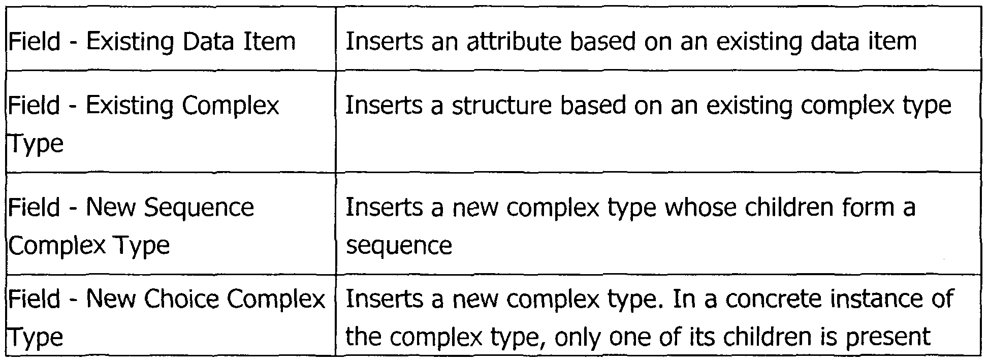
When selecting "Create Child" or "Create Sibling", five option are offered (on the top level shown in Fig. 21, the option "Create Sibling is disabled). This is illustrated in the following table:
Figure imgf000019_0001
If, in the user interface of Fig. 21, the option "Existing Data Item" is chosen, the user interface of Fig. 22 is displayed. The user interface of Fig. 22 constitutes a data item selection dialog that allows for a re-use of an existing data item included in the repository database. All currently loaded data items are shown in the lower part of the user interface in Fig. 21. If the required data item is not yet shown, a search for this data item can be initiated based on search criteria that may be specified in the upper part of the user interface of Fig. 22. Once the data item that is to be inserted in the newly created complex type is selected and the button "OK" is clicked, a new field for the complex type based on the selected data item is created. In this context the user interface of Fig. 23 will be displayed and an appropriate name for this field can be entered.
If, in the user interface of Fig. 21, the option "Existing Complex Type" is chosen, the user interface of Fig. 24 is displayed. The user interface of Fig. 24 constitutes a complex type selection dialog. All currently loaded complex types are displayed in the result list in the lower part of the user interface of Fig. 24. If the required complex type is not yet displayed, a search can be initiated based on search criteria that may be specified in the upper part of the user interface of Fig. 24. Once the complex type that is to be inserted in the newly created complex type is selected and the button "OK" is clicked, a new field based on the selected complex type is created as shown in Rg. 25.
If, in the user interface of Fig. 21, the option "New Sequence Complex Type" is chosen, the user interface of Fig. 26 is displayed for creation of a new complex type. In the user interface of Fig. 26, the new complex type may be given a characteristic name and the parameter "Kind" is preset to "Sequence" (see Fig. 27). In a similar manner, the parameter "Kind" will be preset to "Choice" if the user selects the option "New Choice Complex Type" in the user interface of Fig. 21.
The modeling tool of the present embodiment not only allows for a creation of a new complex type, but also for the creation of a new data item (that will then also be stored in the repository database). In the modeling tool, data items are primarily used for the definition of service parameters. Every leaf in the input or output tree of a service will be based on a data item. In general, existing data items should be reused as often as possible (as explained with reference to Figs. 21 to 23). However, there may still be situations in which the creation of new data items is unavoidable. A new data item will always be a specific data item, meaning that it is created in a specific domain, but with its significance and use by other domains it may become a core data item. Core data items represent the company's main data dictionary.
Fig. 28 shows a user interface that allows for the definition of data item properties for a data item that is to be newly created. The properties include a name, description, length, category, a parent and software component. In the present embodiment, data items must always belong to a particular software component. The initial properties are explained in more detail in the following table:
Figure imgf000020_0001
Figure imgf000021_0001
Once the parameters for a new data item have been specified, the "OK" button of the user interface of Fig. 28 may be clicked to create the date item. The data item may later be edited via the data items properties user interface shown in Fig. 29. This user interface has five tabs, namely "Basic", "Physical", "Business", "GUI" and "Lifecycle" as shown in Figs. 29, 30, 31, 32 and 33, respectively.
The "Basic" properties as shown in Fig. 29 include the following:
Figure imgf000021_0002
Figure imgf000022_0001
The "Physical" properties as shown in Fig. 30 allow for a specification of some implementation-specific information already on the model level in relation to the data item newly created. The physical properties that may be specified include the following:
Figure imgf000022_0002
The "Business" (or application) properties as shown in Rg. 31 include the following:
Figure imgf000023_0001
The "GUI" properties as shown in Fig. 32 are used to control the presentation of data items in the respective user interfaces. Care will be taken that data items are always shown to the user in the same way and with the same labeling. The "GUI" properties include the following:
Figure imgf000023_0002
The "Lifecycle" properties as shown in Fig. 33 reflect the current state of the particular data item ("DI"). These properties are primarily used for data item reviews. Most of the settings can only be set and changed by a user having the corresponding authorization ("Data Manager"). The "Lifecycle" properties include the following:
Figure imgf000024_0001
Input and output parameters of a service are composite tree structures (in the form of "complex types"). They are displayed in the modeling tool in a similar manner like folder structures in a file system. That is, complex types correspond to folders, while fields (or attributes) correspond to files. Every field must be assigned to a data item.
The modeling tool permits the specification of input and output parameters (i.e. the creation of attributes) either via a tree editor (step 2a in Fig. 11) or, alternatively, via a graphical editor (step 2b in Fig. 11). In the following, the tree editor will be discussed first with reference to the user interfaces shown in Figs. 34 to 36. Opening a service and successively selecting the "Interface" (see Fig. 14) and the "Tree" tabs opens the editor for input and output parameters shown in Fig. 34. The pull-down menu in the upper part allows for a switching between "Input" and "Output". The respective structure of the input or output complex type is shown in the left frame. In the right frame, the properties of the selected field can be described. Right-clicking of an element in the complex type shown in the left frame creates new input or output fields (Fig. 35). Several possibilities are offered when selecting "Create Child" or "Create Sibling" (see also Fig. 21 and corresponding description):
Figure imgf000025_0001
Inserting a sibling creates an element on the same level; inserting a child creates a child to an element. A leaf attribute, based on a data item type, can, of course, not have any children.
It should be noted that no new data items can be created in the editor. New data items can only be created in the data item explorer as discussed above in context with Figs. 28 to 33. Further, it is not possible to change the properties of a data item directly in the service or complex type editor. The user interface of Fig. 36 shows an example of an "Input" complex type with an element of the "choice" complex type as displayed by the tree editor.
Opening a service and successively selecting the "Interface" (see Fig. 14) and the "Graphical" tabs opens the graphical editor for input and output parameters shown in Fig. 37. In the graphical editor of Fig. 37, input and output parameters are shown in parallel in their respective hierarchical structure. Different kinds of complex types may graphically be represented in different colors. The toolkit on the left side of Fig. 37 allows for a change of the interface with the following options:
Figure imgf000026_0001
As has been mentioned above, complex types can be used as input and output parameters (or parameter sets) of a service. Mappings (step 3 in Fig. 11) now define how a complex type is transferred into another complex type and are thus primarily used for mapping the input parameters of a specific service to its output parameters as illustrated in Fig. 38 for two exemplary complex types. Mapping an input to an output complex type of a service means that one specifies the "algorithm" of the service. It also means that the output can directly be calculated from the input, without calling another service. Mappings are also used for mapping the input parameters of a specific service to database tables or for mapping output parameters of a first service to input parameters of a second service.
In the modeling tool, mappings are defined on a "Mappings" page of the service editor. In order to be handled correctly by the subsequent artifact generator, mappings have to adhere to certain naming conventions, depending on the mapping type. For each mapping a developer can define a name. There are no technical restrictions on these names, but special characters should be avoided as the names will also be used as names in the generated code. If there is more than one mapping in a particular entity service, the same name should be used for all the mappings. In process services, the same name should be used for two substep mappings. In order to create a new mapping, the "Add" button in the "Mappings" page (see Fig. 39) of the service editor has to be clicked. The "Mappings" page can be reached via the "Mappings" tab of the user interface shown in Fig. 14. In response to activation of the "Add" button, the main properties of the mapping can be defined by selecting a mapping type via a window as illustrated in Fig. 40. The mapping kind influences the generation of the service code frame (the "construct" that can be manually completed if required). It does not influence the functionalities of the service editor (such as mapping source, mapping target, mapping operation).
In the present embodiment, there are six kinds of mappings: Input, Output, Restriction, Substep Input (Invoke or Call), Substep Output and Internal Mapping. The properties of these mapping kinds are summarized in the following table:
Figure imgf000027_0001
As mentioned above, mappings may also be used as a vehicle for transferring data between two individual services. An exemplary scenario is illustrated in Fig. 41. The example shows how the service "GetItemList_Vl_O" (A) is called within the service "GetSingleKunde_Vl_0" (B). A first mapping is used for calling service "B", and a second mapping is used for returning the result of service "B" to service "A". A corresponding user interface is shown in Fig. 42. First, the input complex type of service "A" is mapped to the input complex type of service "B" in order to provide the necessary information to service "B". Next, the output complex type of service "B" is mapped to the output complex type of service "A". This means that the return parameters from the called service "B" are transferred to the output parameters of "A" (see Fig. 43).
Mapping sources and mapping targets can either be chosen manually or via the "Use Service" button of the user interface shown in Figs. 39, 42 and 43. Then, a search dialog appears that permits the selection of a service as a substep. After the selection has been confirmed, the mapping sources and mapping targets are offered as shown in the user interface of Fig. 44. This user interface offers the following options:
Use Input Uses the service input
Use Output Uses the service output
Use Other ... Uses another complex type, A search window is opened for finding the complex type
In addition to defining mapping sources and mapping targets, mapping operations have to be defined. A mapping operation defines how individual input fields are transferred to the output fields. Fig. 45 shows a user interface in which the copy operation is illustrated. Such an operation is for example useful for transferring data between a database, via one or more entity services and/or process services, and a presentation service.
In the user interface of Fig 45, a mapping may be added to a service by clicking one field in the mapping source section, one field in the mapping target section, and by activating the "Add" button. If required, more complex operations could be defined as well.
The modeling tool additionally permits error messages management for a service that is to be modeled. Error messages management (step 4 in Fig. 11) will now be explained in more detail with reference to the user interfaces of Figs. 46 to 52. In the service editor start page as illustrated in Fig. 14, the "Error Messages" page (shown in Fig. 46) can be reached via the corresponding "Error Messages" tab. Error messages already defined for the particular service are displayed automatically in the table "Associated user error messages". The user interface of Fig. 46 shows the page before any messages have been associated with the exemplary (business) service GetAddressinglmageList.
Two types of message can be associated with a business service: Subcomponent- specific messages and Common messages. Subcomponent-specific messages can be associated with the service by clicking the button "GAC messages...", where <GAC> is the software subcomponent ID in which the services is defined. Likewise, Common messages can be associated with the service by clicking the button "Common messages...". Clicking on either of these two buttons results in a dialog user interface as shown in Fig. 47.
The table on the left hand side of the dialog user interface shows all possible messages associated with the subcomponent (or, in the "Common messages" scenario, of Common messages). Selecting a row of the table displays a summary of the message on the right hand side of the dialog. It is possible that the user interface displays no messages, and instead displays an empty table indicating that no error messages have been defined for the subcomponent in question.
Messages already associated with the service will already be checked when the dialog is opened. To specify that a message should be associated with the service, the checkbox of the message has to be marked. To specify that a message should be disassociated 'with the service, the checkbox of the message has to be cleared. Finally, to make the association, the "Associate messages" button has to be clicked.
Fig. 48 shows the original editor screen after both subcomponent-specific and common messages have been added. The user interface as shown in Fig. 48 offers to indicated a "Message Severity". For each message, one of the following options may be selected: "Warning", "Exception" or "Severe"
As mentioned above in context with mapping, a service may call additional services. These calls are defined in the "Mappings" tab of the service editor. After creating a service mappings, one may reopen the services that are to be called. In the tab "Mapping", all error messages of the called services are listed. The modeling tool offers the possibility of mapping these "child" error messages into any existing error message which belongs to the service in work as shown in Fig. 49. In this context, one or more child messages may be selected first, and then the option "Map to..." may be chosen and one error message can be selected out of the list as shown in Fig. 50. The child messages will be mapped to the selected message. After this action, the corresponding information will be displayed in the column "Mapped to" as shown in Fig. 51. On the tab "ErrorMessages", all messages which map child messages are marked with a check-mark (see Fig. 52). Additionally, a mechanism is provided for removing mappings.
As an example, when generating Cobol service code, for each error message the following comment will be written into the source:
* <Swsdd>:<MessagId> < Productive text in english>
The corresponding output code can look as follows:
productive Application Error Messages to use for this Service:
* GACOOOOl Invalid input data: {Field}
* GAQOOOIl CIF Root {Root}, {Clnr} don't exist or has no business relationship * GAC: 00012 Business relationship {Busrel-ID} don t exist
* GAC:00013 The relationship management {Role-OE-Krz} already exists
Once the error messages have been specified for a particular service, top-down modeling is finished and the service model can be transferred to the generator for generating the required artifacts.
As an alternative to the top-down modeling approach discussed above, bottom-up modeling can be used (see Figs. 5 and 10). This modeling type uses some previously defined artifacts to ensure automated fill-out of repository meta information. The automated processes are called wizards. The following wizards are defined for the modeling tool of the present embodiment: Wizard Name Description
Create Presentation Service Create Presentation Service Starting from a
Business Component
Create Entity Service Import Database Table and Create Entity Service
Create Service based on DTD Import DTD
Create Service based on Import Cobol Copybook copybooks
The operation of each of the four wizards illustrated in the above table will now be explained separately starting with the creation of a presentation service using an application component as a starting point.
In order to create a presentation service from a backend application (business application or technical application), a presentation component must be created first. The modeling tool can create a presentation service (e.g. WPS) out of an existing application service. In this context, the application service has to be selected first. Once the application service has been selected, a container, i.e. the software subcomponent for the presentation service, has to be chosen. The user interface of Fig. 53 shows the search function provided by the modeling tool in this regard. Because only business applications and technical applications are allowed here, these kinds of software components are set automatically. The user interface of Fig. 53 permits a search for the desired software component. By clicking 1OK1 a software component can be selected and assigned as a container for the presentation service.
The presentation service type has to be selected next via the user interface of Fig. 54. The default presentation service type is "Simple". The version of the presentation service may additionally be entered. In case of a "Simple (Get, Open or Delete)" presentation service ("simple" e.g. with respect to the corresponding database operations), a confirmation dialog user interface as shown in Fig. 55 will be displayed. In case of more complex presentation services (such as a "Modify" presentation service), additional steps will have to be initiate that will not be discussed in more detail here. Clicking the "Finish" button initiates the creation of the requested presentation service. Thereby, elements (objects) are created for the presentation service in the repository database of the modeling tool and the presentation service appears in the software component explorer under the selected application and software subcomponent as shown in Fig. 56. In Fig. 56, the numeral (1) denotes a presentation service created following the instructions for simple presentation service, whereas (2) denotes a presentation service created following the instructions for a "modify" presentation service.
As mentioned above, for bottom-down modeling a further wizard is defined to import a database table and create an entity service. Based for example on a DB2 table definition, a so-called DCLGEN file can be generated containing a description of the table and a mapping to a Cobol copybook. This file can be used for an import of the table definition in the modeling tool. The DB2 table is represented in the modeling tool as a complex type. Creation of this complex type out of a DCLGEN file starts with a table selection dialog as shown in Fig. 57. The directory of DCLGen-Files should already contain the correct path, e.g.
"\DataSets\Shrxtd \SHRXTC1. TRO. DO. DCLGEN".
Entering the DCLGEN file name pattern refreshes the list of tables available. Selection of one or more tables and clicking of the "Import" button initiates creation of a new complex type for each DCLGEN files.
In a next step the one or more created complex types can be selected for the creation of an entity service (see Fig. Ha). The entity service for the selected complex types can be defined via the user interface shown in Fig. 58. The following options exist:
Entity Service Type Type of Entity Service: (Read ,. Search etc) . Read (' Get") of an object
• Search ("GetList") for objects
• Insert ( "Open") a new object
• Update ("Modify") an existing object
• Delete ("Close") an existing object
Figure imgf000033_0001
After the necessary data have been supplied, the software component release and the subcomponent in which the entity service will be created can be selected via the user interface shown in Fig. 62. The release can be opened by use of the "Search" button (if it is not already open). Clicking "Create" will create the entity service in the selected software subcomponent as shown in Fig. 63. If the newly created entity service is opened and the "Mapping" page is displayed, the two mappings are defined as shown in Figs. 64 and 65.
In the following, another example of bottom-down modeling will be explained with reference to the import of an existing DTD. To create a new process service, a software component release must first be opened in the software component explorer of the modeling tool. Then the software subcomponent which should provide the service(s) to be created (service provider) is to be selected. The user interface shown in Fig. 66 allows for a selection of one or more input files containing the existing DTD(s). After the selection has been performed, clicking on the "Next" button initiates parsing or the selected DTDs. The complex types that will be created are then displayed next via a user interface shown in Fig. 67. The import mechanism merges all complex types that are equivalent. Clicking on the "Finish" button starts the import process. After the import has finished, the services are shown in the software component explorer as illustrated in Fig. 68. Now, a further example of bottom-down modeling will be explained with reference to the import of an existing copybook file. To create a new process service, a software component release must be opened in the software component explorer. Then the software subcomponent which should provide the service(s) to be created (service provider) has to be selected. The import of a Cobol copybook file can be performed via the user interface shown in Fig. 69. This user interface offers the following options.
Figure imgf000034_0001
For the input and output copybook files, a file has to be selected (extension is ".cpy" or ".cob") via the user interface of Fig. 70. After setting all fields, the "Import Definition" might look as shown in Fig. 71. Closing this dialog with "OK" will show this particular import as one row in the copybook import dialog (see Fig. 72). As illustrated in Fig. 73, the next task is to assign a data item to every field in the copybooks (by default, all data items are assigned to the "Generic Data Item"). If one or more fields are to be assigned to an existing data item, corresponding steps can be initiated via the "Link selected item(s) to existing Data Items..." button, which launches the data item selection dialog. If a new data item is to be created for one or more fields, this can be initiated via the corresponding button of the user interface of Fig. 73. After finishing these assignments, clicking "Finish" will complete the operation and also complete bottom-up generation of the service model.
Regardless of its creation (top-down or bottom-up), the service model and its individual model elements will at least temporarily be stored in the repository database 302 of the system shown in Fig. 3. If a particular artifact is needed, the service model may then at any time be retrieved from the repository database 302 by the generator 304. The generator will then select one or more template files 306 associated with the underlying service type and with the requested artifact type (e.g. Java code) and transform the service model into an artifact under control of the selected template files 306. Accordingly, one and the same model may form the basis for generating different types of artifacts, including code, test cases, and specifications such as a physical description of a service. For each of these types of artifacts, one or more dedicated template files 306 are provided.
In some cases, the generated artifacts may be constructs (or frames) that will have to be manually completed by entering code (e.g. specific application logic) within protected areas of the construct. Such a modeling approach has the advantage that the service model as such is independent of the application logic, which greatly facilitates the re-use of the service model and its model elements. Moreover, amendments to the application logic do not require changes of the underlying service model.
As has become apparent from the above, the provision of the central repository database permits a guided and highly structured creation of service models. It is ensured that previously defined model elements such as complex types and data items can be shared between software developers and software development projects. This sharing increases the re-use of available model elements and thus reduces redundancies in the modeling process.
It should be noted that in larger software development environments, the central repository database may include more than 5.000 services, more than 25.000 complex types, and more than 5.000 data items. From these numbers the advantages of a central repository becomes apparent. The management of service models and model elements in the repository is much easier (and less resource- consuming) than the management of the corresponding physical artifacts. For this purpose, each element (service, complex type, data item) in the repository may be associated with a unique identifier. The identifier facilitates change management and allows for an (automatic) change modification. Each repository element may additionally be associated with a (re-)use indicator. This indicator may serve for repository management, for example with respect to the deletion and/or archiving of elements that have not been used for a certain period of time. Furthermore, authorization profiles may be defined indicating the (re-)usage rights of individual software developers.
The generative software development approach described herein, with a highly structured repository database assisting the creation of service models, represents an advantageous model-driven approach for implementing a SOA, i.e. an architecture communicating via individually executable services, rather than via objects such as in object-oriented (OO) approaches. It will be appreciated by those skilled in the art that the above-described methods and devices can be adapted or extended in various ways. While the foregoing description makes reference to preferred embodiments, the scope of the invention is defined solely by the claims that follow and the elements recited therein.

Claims

Claims
1. A template-driven system (100) for generating platform-specific artifacts, such as program code, from platform-independent service models, the system comprising:
- a template storage (102) with platform-specific templates, each template including platform-specific model transformation information;
- a repository (104) with i. a plurality of at least essentially platform-independent service model elements and ii. one or more service models modeled from the model elements; and
- a generator (106) adapted to generate platform-specific artifacts by applying the transformation information included in the templates to the service models.
2. The system of claim 1, wherein at least some of the service-model elements are shared by two or more service models.
3. The system of claim 1 or 2, further comprising a service model creator for creating at least one of service model elements and platform-independent service models from the service model elements.
4. The system of one of claims 1 to 3, wherein the service model elements included in the repository are hierarchically structured.
5. The system of claim 4, wherein each service is modeled from one or more first model elements of a higher hierarchy level and one or more second model elements of a lower hierarchy level.
6. The system of claim 5, wherein in the service model each first model element is associated with one or more second model elements, the one or more second model elements constituting attributes of the first model element.
7. The system of claim 5 or 6, wherein the first model elements define at least one of one or more service input parameters and one or more service output parameters.
8. The system of one of claims 5 to 7, wherein the second model elements constitute leaf fields in at least one of a service input parameter tree and a service output parameter tree.
9. The system of one of claims 1 to 8, wherein the service models in the repository are associated with mappings between two or more model elements or between model elements and database tables.
10. The system of claim 9, wherein the mappings define transfer operations between model elements belonging to the same hierarchy level.
11. The system of claim 9 or 10, wherein the mappings defines transfer operations between one or more service input parameters and one or more service output parameters.
12. The system of claim 11, wherein the input parameters and output parameters belong to different services.
13. The system of one of claims 1 to 12, wherein predefined service types are selectable for service modeling.
H.The system of claim 13, wherein the service types include one or more of a process service, an entity service, a presentation service, a technical service, a batch job and a view.
15. The system of claim 13 or 14, wherein the template storage includes at least one dedicated template for each service type.
16. The system of one of claims 1 to 15, wherein there exist a plurality of predefined platform types.
17. The system of claim 16, wherein the template storage includes at least one dedicated template for each platform type.
18. The system of claim 16, wherein the template storage includes for various combinations of service type and platform type at least one dedicated template.
19. The system of one or claims 3 to 18, wherein the model creator allows for a selection of at least one of a service type and a service publicity.
20. The system of one of claims 1 to 19, wherein the generator allows for a selection of a platform type.
21. The system of one of claims 5 to 20, wherein specific kinds of first model elements are defined and selectable via the service model creator for service modeling.
22. The system of one of claims 1 to 21, wherein the generated artifacts include at least one of Java code, Cobol code, HTML code and XML code.
23.A repository database (302) comprising at least essentially platform- independent model elements and service models modeled from the model elements, the service models forming the basis for the generation of platform- specific artifacts under the control of platform-specific templates, each template including platform-specific model transformation information.
24.A method for generating platform-specific artifacts, such as program code, 5 from platform-independent service models, the method comprising:
- providing platform-specific templates, each template including platform- specific model transformation information;
- providing i. a plurality of at least essentially platform-independent service o model elements and ii. one or more service models modeled from the model elements; and
- generating platform-specific artifacts by applying the transformation information included in the templates to the service models. 5
25.A computer program product comprising program code portions for performing the steps of claim 24 when the computer program product is run on one or more computing devices.
o 26.The computer program product of claim 25, stored on a computer-readable recording medium.
PCT/EP2006/003692 2005-04-22 2006-04-21 A technique for platform-independent service modeling WO2006111401A2 (en)

Priority Applications (1)

Application Number Priority Date Filing Date Title
HK08107074.6A HK1112085A1 (en) 2005-04-22 2008-06-25 A technique for platform-independent service modeling

Applications Claiming Priority (2)

Application Number Priority Date Filing Date Title
EP05008925.9 2005-04-22
EP05008925 2005-04-22

Publications (2)

Publication Number Publication Date
WO2006111401A2 true WO2006111401A2 (en) 2006-10-26
WO2006111401A3 WO2006111401A3 (en) 2006-12-28

Family

ID=36570668

Family Applications (1)

Application Number Title Priority Date Filing Date
PCT/EP2006/003692 WO2006111401A2 (en) 2005-04-22 2006-04-21 A technique for platform-independent service modeling

Country Status (5)

Country Link
US (1) US7761844B2 (en)
EP (1) EP1715419A1 (en)
CN (1) CN100573448C (en)
HK (1) HK1112085A1 (en)
WO (1) WO2006111401A2 (en)

Cited By (4)

* Cited by examiner, † Cited by third party
Publication number Priority date Publication date Assignee Title
WO2009065209A1 (en) * 2007-11-23 2009-05-28 International Business Machines Corporation Systems and methods for transforming a business process into reusable services
WO2012031768A1 (en) * 2010-09-10 2012-03-15 Deutsche Telekom Ag Method for producing an application which is capable of being executed on a digital terminal which has a touch-sensitive screen, and apparatus
CN104111826A (en) * 2013-04-19 2014-10-22 杭州新世纪电子科技有限公司 Software project development method and device
US9501273B1 (en) 2015-09-25 2016-11-22 International Business Machines Corporation Data sharing

Families Citing this family (64)

* Cited by examiner, † Cited by third party
Publication number Priority date Publication date Assignee Title
US7962326B2 (en) * 2000-04-20 2011-06-14 Invention Machine Corporation Semantic answering system and method
US8799776B2 (en) * 2001-07-31 2014-08-05 Invention Machine Corporation Semantic processor for recognition of whole-part relations in natural language documents
US9009590B2 (en) * 2001-07-31 2015-04-14 Invention Machines Corporation Semantic processor for recognition of cause-effect relations in natural language documents
US9009658B2 (en) * 2004-03-15 2015-04-14 Ramco Systems Limited Component based software system
US7844942B2 (en) * 2006-06-12 2010-11-30 International Business Machines Corporation System and method for model driven transformation filtering
US20080046858A1 (en) * 2006-08-15 2008-02-21 Zeligsoft Inc. Method and apparatus for merge condition detection
US9031947B2 (en) * 2007-03-27 2015-05-12 Invention Machine Corporation System and method for model element identification
JP4412674B2 (en) * 2007-04-18 2010-02-10 インターナショナル・ビジネス・マシーンズ・コーポレーション Apparatus and method for supporting model-driven development
US7937250B2 (en) * 2007-04-27 2011-05-03 International Business Machines Corporation Method and system for addressing non-functional concerns
US20080312982A1 (en) * 2007-06-15 2008-12-18 International Business Machine Corporation Dynamic Creation of a Service Model
US7970892B2 (en) 2007-06-29 2011-06-28 Microsoft Corporation Tuning and optimizing distributed systems with declarative models
US8239505B2 (en) * 2007-06-29 2012-08-07 Microsoft Corporation Progressively implementing declarative models in distributed systems
US8230386B2 (en) * 2007-08-23 2012-07-24 Microsoft Corporation Monitoring distributed applications
US8225308B2 (en) 2007-10-26 2012-07-17 Microsoft Corporation Managing software lifecycle
US8181151B2 (en) * 2007-10-26 2012-05-15 Microsoft Corporation Modeling and managing heterogeneous applications
US20090113292A1 (en) * 2007-10-26 2009-04-30 Microsoft Corporation Flexibly editing heterogeneous documents
US7974939B2 (en) 2007-10-26 2011-07-05 Microsoft Corporation Processing model-based commands for distributed applications
US8099720B2 (en) 2007-10-26 2012-01-17 Microsoft Corporation Translating declarative models
US8533660B2 (en) * 2007-11-21 2013-09-10 Sap Ag Annotation of models for model-driven engineering
US8869098B2 (en) * 2007-12-05 2014-10-21 International Business Machines Corporation Computer method and apparatus for providing model to model transformation using an MDA approach
US20100058198A1 (en) * 2008-04-16 2010-03-04 Modria, Inc. Collaborative realtime planning using a model driven architecture and iterative planning tools
US8516435B2 (en) * 2008-06-19 2013-08-20 International Business Machines Corporation System and method for generating implementation artifacts for contextually-aware business applications
EP2157508A1 (en) * 2008-08-18 2010-02-24 Software AG SOA-registry, method and platform manager for automatic SOA application deployment
US8495559B2 (en) * 2008-09-09 2013-07-23 International Business Machines Corporation Extracting platform independent models from composite applications
US8813024B2 (en) * 2008-09-22 2014-08-19 International Business Machines Corporation System and a method for cross-platform porting of business application and making them contextually-aware on target platforms
US8020051B2 (en) * 2008-10-20 2011-09-13 Sap Ag Message handling in a service-oriented architecture
US20100138252A1 (en) * 2008-12-02 2010-06-03 International Business Machines Corporation Governing Realizing Services In A Service Oriented Architecture
US10152692B2 (en) 2008-12-03 2018-12-11 International Business Machines Corporation Governing exposing services in a service model
US8316347B2 (en) * 2008-12-05 2012-11-20 International Business Machines Corporation Architecture view generation method and system
US20100145751A1 (en) * 2008-12-10 2010-06-10 Charles Franklin Berry Validation method and system
US8332813B2 (en) * 2008-12-11 2012-12-11 International Business Machines Corporation Service re-factoring method and system
US8224869B2 (en) * 2008-12-16 2012-07-17 International Business Machines Corporation Re-establishing traceability method and system
US8612930B2 (en) * 2009-01-30 2013-12-17 Oracle America, Inc. Methods and apparatus for dynamic class reloading and versioning
JP2012520528A (en) * 2009-03-13 2012-09-06 インベンション マシーン コーポレーション System and method for automatic semantic labeling of natural language text
CN102439594A (en) * 2009-03-13 2012-05-02 发明机器公司 System and method for knowledge research
US8296725B2 (en) * 2009-03-25 2012-10-23 International Business Machines Corporation Framework for variation oriented analysis for service-oriented architecture
US8640085B2 (en) * 2009-07-01 2014-01-28 International Business Machines Corporation Generating a service component architecture (SCA) module with service oriented architecture (SOA) model elements
EP2330469B1 (en) * 2009-12-03 2012-10-31 dspace digital signal processing and control engineering GmbH Method and development environment for generating an executable total control program
US8677309B2 (en) * 2009-12-29 2014-03-18 Oracle International Corporation Techniques for automated generation of deployment plans in an SOA development lifecycle
US8661015B2 (en) * 2010-06-24 2014-02-25 Bizosys Technologies Private Limited Identification of name entities via search, determination of alternative searches, and automatic integration of data across a computer network for dynamic portal generation
US8285800B2 (en) * 2010-06-25 2012-10-09 Compuware Corporation Service model creation using monitored data of the performance management tool
US8719770B2 (en) 2010-09-09 2014-05-06 International Business Machines Corporation Verifying programming artifacts generated from ontology artifacts or models
US8607192B2 (en) 2010-09-15 2013-12-10 International Business Machines Corporation Automating a governance process of creating a new version of a service in a governed SOA
US8726227B2 (en) 2010-09-15 2014-05-13 International Business Machines Corporation Modeling a governance process of establishing a subscription to a deployed service in a governed SOA
US8769483B2 (en) 2010-09-15 2014-07-01 International Business Machines Corporation Automating a governance process of optimizing a portfolio of services in a governed SOA
CN102467405A (en) * 2010-11-12 2012-05-23 鸿富锦精密工业(深圳)有限公司 Measurement program conversion system and method
US8712947B2 (en) 2011-01-27 2014-04-29 International Business Machines Corporation Collaborative system for capture and reuse of software application knowledge and a method of realizing same
US20150149980A1 (en) * 2013-09-11 2015-05-28 Tongling Yucheng Software Technology Co., Ltd. Service model-oriented software operation platform and operation method thereof
US11144333B2 (en) * 2011-07-12 2021-10-12 Tongling Yuchen Software Technology Co., Ltd. Service model-oriented software system and operation method thereof
US8719781B2 (en) 2011-12-01 2014-05-06 Amer Agovic Universal and adaptive software development platform for data-driven applications
US9021420B2 (en) * 2012-03-02 2015-04-28 Xerox Corporation Deployment of business processes in service-oriented architecture environments
US8910115B2 (en) * 2012-04-02 2014-12-09 Kony Solutions, Inc. Systems and methods for application development
US9304746B2 (en) * 2012-06-07 2016-04-05 Carmel-Haifa University Economic Corporation Ltd. Creating a user model using component based approach
CN103973634B (en) * 2013-01-24 2015-03-18 腾讯科技(深圳)有限公司 Application data construction method, related equipment and network system
US9047325B2 (en) * 2013-04-08 2015-06-02 International Business Machines Corporation Modularizing complex XML data for generation and extraction
US10073867B2 (en) 2013-05-17 2018-09-11 Oracle International Corporation System and method for code generation from a directed acyclic graph using knowledge modules
US10296652B2 (en) * 2013-09-21 2019-05-21 Oracle International Corporation Method and system for selection of user interface rendering artifacts in enterprise web applications using a manifest mechanism
US9262783B1 (en) * 2014-08-11 2016-02-16 Software Ag System and method for evaluating input based on dynamic grammars
CN104360859B (en) * 2014-11-14 2017-08-25 中国建设银行股份有限公司 A kind of visual service development method and system
US20170168792A1 (en) * 2015-12-15 2017-06-15 Futurewei Technologies, Inc. Space and time aware organization and isolation of components in real time systems
SG10201701962TA (en) * 2016-03-11 2017-10-30 Tata Consultancy Services Ltd System and method for developing mobile based applications using model driven development
CN109117152B (en) * 2018-07-26 2022-02-25 新华三大数据技术有限公司 Service generation system and method
US10922075B2 (en) 2019-04-10 2021-02-16 Morgan Stanley Services Group Inc. System and method for creating and validating software development life cycle (SDLC) digital artifacts
CN112817571B (en) * 2021-02-24 2023-06-30 复旦大学 Man-machine object fusion application modeling method based on scene storyboard

Citations (2)

* Cited by examiner, † Cited by third party
Publication number Priority date Publication date Assignee Title
US6199195B1 (en) * 1999-07-08 2001-03-06 Science Application International Corporation Automatically generated objects within extensible object frameworks and links to enterprise resources
US20020023261A1 (en) * 1999-07-08 2002-02-21 Goodwin Richard Glenn Automatically generated objects within extensible object frameworks and links to enterprise resources

Family Cites Families (19)

* Cited by examiner, † Cited by third party
Publication number Priority date Publication date Assignee Title
US6101500A (en) * 1998-01-07 2000-08-08 Novell, Inc. System and method for managing objects in a hierarchical data structure
US6742175B1 (en) * 1998-10-13 2004-05-25 Codagen Technologies Corp. Component-based source code generator
US6862735B1 (en) * 1999-02-11 2005-03-01 Sun Microsystems, Inc. Mechanism by which platform independent software may bind to and access platform dependent software
US6442748B1 (en) * 1999-08-31 2002-08-27 Accenture Llp System, method and article of manufacture for a persistent state and persistent object separator in an information services patterns environment
US6601234B1 (en) * 1999-08-31 2003-07-29 Accenture Llp Attribute dictionary in a business logic services environment
US6615253B1 (en) * 1999-08-31 2003-09-02 Accenture Llp Efficient server side data retrieval for execution of client side applications
WO2001067309A2 (en) * 2000-03-03 2001-09-13 Radiant Logic, Inc. System and method for providing access to databases via directories and other hierarchical structures and interfaces
US6957230B2 (en) * 2000-11-30 2005-10-18 Microsoft Corporation Dynamically generating multiple hierarchies of inter-object relationships based on object attribute values
WO2002073402A1 (en) * 2001-01-05 2002-09-19 Consystant Design Technologies, Inc. Coordination synthesis for software systems
US6957391B2 (en) * 2001-05-31 2005-10-18 International Business Machines Corporation Application program interface that can maintain similar look and feel of a displayed image regardless of whether the interface is platform dependent or platform independent
US7392483B2 (en) * 2001-09-28 2008-06-24 Ntt Docomo, Inc, Transformation of platform specific graphical user interface widgets migrated between heterogeneous device platforms
AU2002328726A1 (en) * 2001-09-28 2003-04-14 Codagen Technologies Corp. A system and method for managing architectural layers within a software model
US7457846B2 (en) * 2001-10-05 2008-11-25 International Business Machines Corporation Storage area network methods and apparatus for communication and interfacing with multiple platforms
US7340718B2 (en) * 2002-09-30 2008-03-04 Sap Ag Unified rendering
US6952817B1 (en) * 2002-12-04 2005-10-04 Xilinx, Inc. Generating hardware interfaces for designs specified in a high level language
US7478408B2 (en) * 2003-04-04 2009-01-13 Sesma Systems, Inc. System and method for accessing objects in a platform dependent environment from a platform independent environment
US7490332B2 (en) * 2003-04-04 2009-02-10 Sesma Systems, Inc. System and method for accessing ActiveX objects in a platform dependent environment from objects in a platform independent environment
US7941784B2 (en) * 2005-03-14 2011-05-10 Research In Motion Limited System and method for generating component based applications
US7418710B1 (en) * 2007-10-05 2008-08-26 Kaspersky Lab, Zao Processing data objects based on object-oriented component infrastructure

Patent Citations (2)

* Cited by examiner, † Cited by third party
Publication number Priority date Publication date Assignee Title
US6199195B1 (en) * 1999-07-08 2001-03-06 Science Application International Corporation Automatically generated objects within extensible object frameworks and links to enterprise resources
US20020023261A1 (en) * 1999-07-08 2002-02-21 Goodwin Richard Glenn Automatically generated objects within extensible object frameworks and links to enterprise resources

Non-Patent Citations (1)

* Cited by examiner, † Cited by third party
Title
DAVID FRANKEL, JOHN PARODI: "White Paper Using Model-Driven Architecture to Develop Web Services" INTERNET ARTICLE, [Online] April 2002 (2002-04), XP002385064 IONA Website Retrieved from the Internet: URL:http://www.iona.com/archwebservice/WSM DA.pdf> [retrieved on 2006-06-13] *

Cited By (7)

* Cited by examiner, † Cited by third party
Publication number Priority date Publication date Assignee Title
WO2009065209A1 (en) * 2007-11-23 2009-05-28 International Business Machines Corporation Systems and methods for transforming a business process into reusable services
WO2012031768A1 (en) * 2010-09-10 2012-03-15 Deutsche Telekom Ag Method for producing an application which is capable of being executed on a digital terminal which has a touch-sensitive screen, and apparatus
CN104111826A (en) * 2013-04-19 2014-10-22 杭州新世纪电子科技有限公司 Software project development method and device
US9501273B1 (en) 2015-09-25 2016-11-22 International Business Machines Corporation Data sharing
US9674309B2 (en) 2015-09-25 2017-06-06 International Business Machines Corporation Data sharing
US9705988B2 (en) 2015-09-25 2017-07-11 International Business Machines Corporation Data sharing
US10075535B2 (en) 2015-09-25 2018-09-11 International Business Machines Corporation Business logic sharing

Also Published As

Publication number Publication date
US20060242195A1 (en) 2006-10-26
EP1715419A1 (en) 2006-10-25
US7761844B2 (en) 2010-07-20
CN101164044A (en) 2008-04-16
CN100573448C (en) 2009-12-23
HK1112085A1 (en) 2008-08-22
WO2006111401A3 (en) 2006-12-28

Similar Documents

Publication Publication Date Title
US7761844B2 (en) Technique for platform-independent service modeling
US7130863B2 (en) Method for enhancing object-oriented programming through extending metadata associated with class-body class-head by adding additional metadata to the database
CA2504082C (en) Method and apparatus for generating user interfaces based upon automation with full flexibility
US7788238B2 (en) Extensible object-modelling mechanism
US20020092004A1 (en) Methods and systems for automatically generating software applications
JP2004280821A (en) Software business process model
JP2004280820A (en) Framework for supporting business software application
US20040003091A1 (en) Accessing a remote iSeries or AS/400 computer system from an integrated development environment
US8707171B2 (en) Service registry policy editing user interface
Cheong et al. Frame-based method for customizing generic software architectures
Jelinek et al. GUI generation from annotated source code
CN102289448B (en) The entity of visit data access layer
Kalnins et al. Metamodel specialization for graphical language support
Bettig et al. An object-oriented program shell for integrating CAD software tools
KR100609240B1 (en) Method and apparatus for generating diagram modeling tools with user&#39;s customization requirements based on mof meta-models
Duddy et al. Design of a model-generated repository as a service for USDL
Kulkarni et al. A model-driven approach for developing business applications: experience, lessons learnt and a way forward
Noronha et al. Extending a structured document model with version control
Kovse et al. Supporting mass customization by generating adjusted repositories for product configuration knowledge
Heimann et al. Integrated Product and Process Management for Engineering Design in Manufacturing Systems1
Porres et al. A generic deep copy algorithm for MOF-based models
Ahmed-Nacer Towards a new approach on software process evolution
Çetinkaya A metamodel for the high level architecture object model
Ayesh Essential UMLTM Fast: Using SELECT Use Case Tool for Rapid Applications Development
Amelunxen et al. Creating Well-Structured Specifications in MOFLON

Legal Events

Date Code Title Description
121 Ep: the epo has been informed by wipo that ep was designated in this application
DPE1 Request for preliminary examination filed after expiration of 19th month from priority date (pct application filed from 20040101)
WWE Wipo information: entry into national phase

Ref document number: 200680013571.2

Country of ref document: CN

NENP Non-entry into the national phase

Ref country code: DE

WWW Wipo information: withdrawn in national office

Ref document number: DE

WWE Wipo information: entry into national phase

Ref document number: 4426/KOLNP/2007

Country of ref document: IN

NENP Non-entry into the national phase

Ref country code: RU

WWW Wipo information: withdrawn in national office

Ref document number: RU

122 Ep: pct application non-entry in european phase

Ref document number: 06724497

Country of ref document: EP

Kind code of ref document: A2

WWW Wipo information: withdrawn in national office

Ref document number: 6724497

Country of ref document: EP