WO2013192247A1 - System and method for calculating and reporting maximum allowable operating pressure - Google Patents
System and method for calculating and reporting maximum allowable operating pressure Download PDFInfo
- Publication number
- WO2013192247A1 WO2013192247A1 PCT/US2013/046441 US2013046441W WO2013192247A1 WO 2013192247 A1 WO2013192247 A1 WO 2013192247A1 US 2013046441 W US2013046441 W US 2013046441W WO 2013192247 A1 WO2013192247 A1 WO 2013192247A1
- Authority
- WO
- WIPO (PCT)
- Prior art keywords
- maop
- pipeline
- determination
- report
- fve
- Prior art date
Links
- 238000000034 method Methods 0.000 title claims description 116
- 238000004458 analytical method Methods 0.000 claims abstract description 30
- 238000003860 storage Methods 0.000 claims abstract description 17
- 238000012545 processing Methods 0.000 claims description 17
- 238000012360 testing method Methods 0.000 description 195
- 238000013461 design Methods 0.000 description 94
- 238000004364 calculation method Methods 0.000 description 81
- 239000000463 material Substances 0.000 description 75
- 230000008569 process Effects 0.000 description 32
- 238000010586 diagram Methods 0.000 description 22
- 238000010276 construction Methods 0.000 description 21
- 239000007789 gas Substances 0.000 description 16
- 238000007689 inspection Methods 0.000 description 15
- 239000003638 chemical reducing agent Substances 0.000 description 14
- 230000006870 function Effects 0.000 description 13
- 238000009434 installation Methods 0.000 description 12
- QCAWEPFNJXQPAN-UHFFFAOYSA-N methoxyfenozide Chemical compound COC1=CC=CC(C(=O)NN(C(=O)C=2C=C(C)C=C(C)C=2)C(C)(C)C)=C1C QCAWEPFNJXQPAN-UHFFFAOYSA-N 0.000 description 12
- 238000010200 validation analysis Methods 0.000 description 11
- 230000000712 assembly Effects 0.000 description 9
- 238000000429 assembly Methods 0.000 description 9
- 230000008859 change Effects 0.000 description 7
- 238000011835 investigation Methods 0.000 description 7
- 230000001105 regulatory effect Effects 0.000 description 7
- 230000008439 repair process Effects 0.000 description 6
- 230000035882 stress Effects 0.000 description 6
- 230000037303 wrinkles Effects 0.000 description 6
- 238000009826 distribution Methods 0.000 description 5
- 230000009467 reduction Effects 0.000 description 5
- 238000012552 review Methods 0.000 description 5
- 238000013500 data storage Methods 0.000 description 4
- 230000007613 environmental effect Effects 0.000 description 4
- 239000000446 fuel Substances 0.000 description 4
- 238000012423 maintenance Methods 0.000 description 4
- VNWKTOKETHGBQD-UHFFFAOYSA-N methane Chemical compound C VNWKTOKETHGBQD-UHFFFAOYSA-N 0.000 description 4
- 229910000831 Steel Inorganic materials 0.000 description 3
- 230000005540 biological transmission Effects 0.000 description 3
- 238000013479 data entry Methods 0.000 description 3
- 238000004519 manufacturing process Methods 0.000 description 3
- 230000003287 optical effect Effects 0.000 description 3
- 239000010959 steel Substances 0.000 description 3
- 239000004698 Polyethylene Substances 0.000 description 2
- 230000009471 action Effects 0.000 description 2
- 239000008186 active pharmaceutical agent Substances 0.000 description 2
- 239000003795 chemical substances by application Substances 0.000 description 2
- 238000004891 communication Methods 0.000 description 2
- 238000004590 computer program Methods 0.000 description 2
- 239000004567 concrete Substances 0.000 description 2
- 230000008878 coupling Effects 0.000 description 2
- 238000010168 coupling process Methods 0.000 description 2
- 238000005859 coupling reaction Methods 0.000 description 2
- 239000013078 crystal Substances 0.000 description 2
- 238000013502 data validation Methods 0.000 description 2
- 230000000694 effects Effects 0.000 description 2
- 238000011156 evaluation Methods 0.000 description 2
- 239000012212 insulator Substances 0.000 description 2
- 238000012986 modification Methods 0.000 description 2
- 230000004048 modification Effects 0.000 description 2
- 239000003345 natural gas Substances 0.000 description 2
- -1 polyethylene Polymers 0.000 description 2
- 229920000573 polyethylene Polymers 0.000 description 2
- 230000000644 propagated effect Effects 0.000 description 2
- 238000000275 quality assurance Methods 0.000 description 2
- 238000003908 quality control method Methods 0.000 description 2
- 230000003014 reinforcing effect Effects 0.000 description 2
- 230000004044 response Effects 0.000 description 2
- 238000012795 verification Methods 0.000 description 2
- BTFMCMVEUCGQDX-UHFFFAOYSA-N 1-[10-[3-[4-(2-hydroxyethyl)-1-piperidinyl]propyl]-2-phenothiazinyl]ethanone Chemical class C12=CC(C(=O)C)=CC=C2SC2=CC=CC=C2N1CCCN1CCC(CCO)CC1 BTFMCMVEUCGQDX-UHFFFAOYSA-N 0.000 description 1
- 229910000975 Carbon steel Inorganic materials 0.000 description 1
- SWECWXGUJQLXJF-BTJKTKAUSA-N Dimetindene maleate Chemical compound OC(=O)\C=C/C(O)=O.CN(C)CCC=1CC2=CC=CC=C2C=1C(C)C1=CC=CC=N1 SWECWXGUJQLXJF-BTJKTKAUSA-N 0.000 description 1
- 101100289061 Drosophila melanogaster lili gene Proteins 0.000 description 1
- 101000578920 Homo sapiens Microtubule-actin cross-linking factor 1, isoforms 1/2/3/5 Proteins 0.000 description 1
- 102100028322 Microtubule-actin cross-linking factor 1, isoforms 1/2/3/5 Human genes 0.000 description 1
- 201000007902 Primary cutaneous amyloidosis Diseases 0.000 description 1
- 230000032683 aging Effects 0.000 description 1
- 238000013459 approach Methods 0.000 description 1
- 239000010962 carbon steel Substances 0.000 description 1
- 238000005266 casting Methods 0.000 description 1
- 239000003518 caustics Substances 0.000 description 1
- 230000001413 cellular effect Effects 0.000 description 1
- 239000011248 coating agent Substances 0.000 description 1
- 238000000576 coating method Methods 0.000 description 1
- 239000002131 composite material Substances 0.000 description 1
- 239000004035 construction material Substances 0.000 description 1
- 230000007797 corrosion Effects 0.000 description 1
- 238000005260 corrosion Methods 0.000 description 1
- 238000007405 data analysis Methods 0.000 description 1
- 230000002950 deficient Effects 0.000 description 1
- 230000001419 dependent effect Effects 0.000 description 1
- 230000009977 dual effect Effects 0.000 description 1
- 230000005611 electricity Effects 0.000 description 1
- 238000005516 engineering process Methods 0.000 description 1
- 229920006333 epoxy cement Polymers 0.000 description 1
- 230000003628 erosive effect Effects 0.000 description 1
- 238000001914 filtration Methods 0.000 description 1
- 239000012530 fluid Substances 0.000 description 1
- 230000004927 fusion Effects 0.000 description 1
- 231100001261 hazardous Toxicity 0.000 description 1
- 230000036541 health Effects 0.000 description 1
- 230000008676 import Effects 0.000 description 1
- 230000000977 initiatory effect Effects 0.000 description 1
- 230000000266 injurious effect Effects 0.000 description 1
- 150000002500 ions Chemical class 0.000 description 1
- 230000008376 long-term health Effects 0.000 description 1
- 230000007774 longterm Effects 0.000 description 1
- 238000005259 measurement Methods 0.000 description 1
- 239000002184 metal Substances 0.000 description 1
- 238000012544 monitoring process Methods 0.000 description 1
- 210000002445 nipple Anatomy 0.000 description 1
- 230000008520 organization Effects 0.000 description 1
- 229960004265 piperacetazine Drugs 0.000 description 1
- 208000014670 posterior cortical atrophy Diseases 0.000 description 1
- 238000000513 principal component analysis Methods 0.000 description 1
- 230000002787 reinforcement Effects 0.000 description 1
- 239000011435 rock Substances 0.000 description 1
- 238000010079 rubber tapping Methods 0.000 description 1
- 238000007778 shielded metal arc welding Methods 0.000 description 1
- 239000011343 solid material Substances 0.000 description 1
- 238000005482 strain hardening Methods 0.000 description 1
- 230000000153 supplemental effect Effects 0.000 description 1
- 238000012546 transfer Methods 0.000 description 1
- 230000009466 transformation Effects 0.000 description 1
- 230000001131 transforming effect Effects 0.000 description 1
- 230000007704 transition Effects 0.000 description 1
- 238000011144 upstream manufacturing Methods 0.000 description 1
- 238000012800 visualization Methods 0.000 description 1
- 238000003466 welding Methods 0.000 description 1
Classifications
-
- G—PHYSICS
- G05—CONTROLLING; REGULATING
- G05D—SYSTEMS FOR CONTROLLING OR REGULATING NON-ELECTRIC VARIABLES
- G05D16/00—Control of fluid pressure
- G05D16/20—Control of fluid pressure characterised by the use of electric means
-
- F—MECHANICAL ENGINEERING; LIGHTING; HEATING; WEAPONS; BLASTING
- F17—STORING OR DISTRIBUTING GASES OR LIQUIDS
- F17D—PIPE-LINE SYSTEMS; PIPE-LINES
- F17D5/00—Protection or supervision of installations
-
- F—MECHANICAL ENGINEERING; LIGHTING; HEATING; WEAPONS; BLASTING
- F17—STORING OR DISTRIBUTING GASES OR LIQUIDS
- F17D—PIPE-LINE SYSTEMS; PIPE-LINES
- F17D1/00—Pipe-line systems
Definitions
- Some embodiments of the invention provide a pipeline analysis system for analyzing a pipeline dataset to determine compliance with desired maximum allowable pipeline operating pressures.
- the pipeline analysis system can revise pipeline component data to specify pipeline components that are in compliance with desired maximum allowable pipeline operating pressures.
- included pipeline component data can correspond to an existing or planned physical pipeline.
- the pipeline analysis system can enable revision of the pipeline component data to specify at least one pipeline component having at least one different characteristic than was originally specified in the dataset.
- the revised dataset can be analyzed to determine the maximum allowable pipeline operating pressure for the existing or planned physical pipeline.
- the pipeline analysis system comprises a processor, and a first non-transitory computer-readable storage medium for tangibly storing thereon program logic for execution by the processor.
- the program logic comprises logic executed by the processor for receiving and tangibly storing on a second non-transitory computer-readable storage medium a dataset including pipeline component data corresponding to an existing or planned physical pipeline.
- Some embodiments include logic executed by the processor for analyzing the dataset to determine compliance with desired maximum allowable pipeline operating pressures.
- Some embodiments also include logic executed by the processor for enabling revision of the pipeline component data to specify pipeline components that are in compliance with desired maximum allowable pipeline operating pressures, and logic executed by the processor for providing an exception report listing non- compliant pipeline components.
- the pipeline component data includes data corresponding to pipe segments, pipe fittings and pipe valves.
- Some embodiments include batch processing techniques for analyzing the data set.
- the dataset contains pipeline component data for an entire pipeline.
- the pipeline analysis system analyzes the dataset at least in part by comparing the pipeline component data to an industry standard pipeline database stored on a third non-transitory computer-readable medium. DESCRIPTION OF THE DRAWINGS
- FIG. 1 is a flow chart showing a determination of whether an identified feature is a pipe or a pipe component according to one embodiment of the invention.
- FIG. 2 is a flow chart showing a specified minimum yield strength (SMYS) test for zero according to one embodiment of the invention.
- STYS specified minimum yield strength
- FIG. 3 is a flow chart showing a decision point relating to specified minimum yield strength (SMYS) indicating an assumption was used or data was obtained by a field investigation according to one embodiment of the invention.
- STYS specified minimum yield strength
- FIG. 4 is a flow chart showing the OD - maximum allowable operating pressure (MAOP) Report according to one embodiment of the invention.
- FIG. 5 is a flow chart showing a method for OD calculation according to one embodiment of the invention.
- FIG. 6 is a flow chart showing an OD calculation and assignment according to one embodiment of the invention.
- FIG. 7 is a flow chart showing an OD 2 assignment according to one embodiment of the invention.
- FIGS. 8A-8B are a flow chart showing methods for LS factor assignment according to one embodiment of the invention.
- FIG. 9 is a flow chart showing the valid test for >30% SMYS? 1 class out? according to one embodiment of the invention.
- FIGS. 10A-10B are a flow chart showing the strength test factor relative to converted date for table search according to one embodiment of the invention.
- FIG. 11 is a flow chart showing methods related to the supported feature MAOP according to one embodiment of the invention.
- FIGS. 12A-12B are a flow chart showing methods for the STPR supported MAOP according to one embodiment of the invention.
- FIGS. 13A-13B are a flow chart showing the MAOP according to one embodiment of the invention.
- FIG. 14 is a flow chart showing the code compliant allowable pressure according to one embodiment of the invention.
- FIG. 15 is a flow chart showing the % SMYS (specified minimum yield strength) @ MAOP of record when a rated fitting is not used according to one embodiment of the invention.
- FIG. 16 is a flow chart showing the % SMYS at the supported feature MAOP according to one embodiment of the invention.
- FIG. 17 is a flow chart showing the % SMYS @ MAOP of record according to one embodiment of the invention.
- FIG. 18 is a flow chart showing the limited MAOP according to one embodiment of the invention.
- FIG. 19 is a flow chart showing the design factor according to one embodiment of the invention.
- FIG. 20 is a flow chart showing the WT - MAOP is equal to WT @ minimum DP location according to one embodiment of the invention.
- FIG. 21 is a flow chart showing the WT footnote - MAOP report indicating an assumption was used or data was obtained by field investigation according to one embodiment of the invention.
- FIG. 22 is a flow chart showing the fitting rating - MAOP report is N/A if N/A is an unknown according to one embodiment of the invention.
- FIG. 23 is a flow chart showing the footnote fitting rating - MAOP report indicating an assumption was used or data was obtained by field investigation according to one embodiment of the invention.
- FIGS. 24A-24B are a flow chart showing the feature MAOP according to one embodiment of the invention.
- FIG. 25 is a flow chart showing the joint efficiency factor - MAOP report for CAP equals N/A, otherwise equals LS Factor according to one embodiment of the invention.
- FIG. 26 is a flow chart showing the test pressure - the MAOP report equals N/A if no test according to one embodiment of the invention.
- FIG. 27 is a flow chart showing the footnote MAOP [R] - the maximum MAOP report equals B if A pressure reduction from MAOP per record according to one embodiment of the invention.
- FIG. 28 is a flow chart showing the MAOP per design - the MAOP report is either one class out, fitting MAOP, or minimum of DP @ 1 or 2 according to one embodiment of the invention.
- FIG. 29 is a flow chart showing the test year equaling MAOP report equals test one? according to one embodiment of the invention.
- FIG. 30 is a flow chart showing the % SMYS Per R - MAOP report equals minimum DP Location @ MAOP per recon according to one embodiment of the invention.
- FIG. 31 is a flow chart showing the footnote MAOP [D] - MAOP report equals A when MAOP per design is one class out according to one embodiment of the invention.
- FIGS. 32A-32B are a flow chart showing the operating in class according to one embodiment of the invention.
- FIGS. 33A-33B are a flow chart showing the MAOP limit factor according to one embodiment of the invention.
- FIG. 34 is a flow chart showing the calculated DP @ 1 according to one embodiment of the invention.
- FIG. 35 is a flow chart showing the calculated DP @ 2 according to one embodiment of the invention.
- FIG. 36 is a flow chart showing the minimum DP location according to one embodiment of the invention.
- FIG. 37 is a flow chart showing the DP according to one embodiment of the invention.
- FIG. 38 is a flow chart showing the seam type footnote - MAOP report indicating an assumption was used or data was obtained by field investigation according to one embodiment of the invention.
- FIG. 39 is a flow chart showing the Fitting MAOP from a lookup table with WOG and ANSI values according to one embodiment of the invention.
- FIGS. 40A-40B are a flow chart showing the seam type according to one embodiment of the invention.
- FIG. 41 is a schematic diagram showing the structure for the analysis template and MAOP report including the PFL body with the pipeline features, and FVE columns which produces the MAOP report according to one embodiment of the invention.
- FIG. 42 is an example of a MAOP report according to one embodiment of the invention.
- FIG. 43 is a flow chart showing the process for the MAOP data validation project according to one embodiment of the invention.
- FIGS. 44A-44C is a spreadsheet diagram showing the feature specifications for the FVE columns according to one embodiment of the invention.
- FIGS. 45A-45B are a spreadsheet diagram showing the structure for the MAOP report according to one embodiment of the invention.
- FIG. 46 is a spreadsheet diagram showing the calculations used in determining a design pressure (DP) for the MAOP report according to one embodiment of the invention.
- FIG. 47 is a spreadsheet diagram showing the MAOP per test for the MAOP report Calculations according to one embodiment of the invention.
- FIG. 48 is a spreadsheet diagram showing another view of the MAOP per test for the MAOP report calculations according to one embodiment of the invention.
- FIG. 49 is a spreadsheet diagram showing the Assumptions for the MAOP report footnote guide according to one embodiment of the invention.
- FIG. 50 is a spreadsheet diagram showing the 61 1 calculations for the MAOP report footnote guide according to one embodiment of the invention.
- FIG. 51 is a spreadsheet diagram showing reduced pressure operation compared to recon for the MAOP report footnote guide according to one embodiment of the invention.
- FIG. 52 is a flow chart showing the MAOP report upload and centralized calculator for IntrepidTM software according to one embodiment of the invention.
- FIG. 53 is a flow chart showing the centralized calculator for IntrepidTM according to one embodiment of the invention.
- FIG. 54 depicts a system architecture and MAOP report methods including batch execution across all the pipeline segments in the PODS database in accordance with some embodiments of the invention.
- FIG. 55 shows one example of a software front-end interface for selecting MAOP reports including batch processing MAOP reports in accordance with some embodiments of the invention.
- FIG. 56 illustrates a pipeline route with associated pipeline segments and associated data tables in accordance with one embodiment of the invention.
- FIG. 57 illustrates methods for MAOP calculations using one embodiment of the system architecture of FIG. 54 including batch processing of compliance reports in accordance with some embodiments of the invention.
- FIG. 58 illustrates methods to determine and set override values based on whether MAOP calculator values are null or unknown in accordance with some embodiments of the invention.
- FIG. 59 illustrates methods to input one or more pipeline designs using a computer aided design software package 5910 for use in MAOP calculations in accordance with one embodiment of the invention.
- FIG. 60 shows one example of system architecture capable of implementation of at least one of the methods or reports as shown in FIGS. 1-53 according to one embodiment of the invention.
- the disclosed system and method assists engineers and operators in efficiently and accurately identifying infrastructure weaknesses so that the weaknesses can be addressed in advance of encountering a negative event.
- the disclosed calculator helps engineers to identify and/or predict potential weaknesses in the high-pressure infrastructure that may eventually lead to a rupture, for example, that may be injurious or monetarily and environmentally costly. Such weaknesses may occur as a result of normal aging and environmental wear on the many components that are used to construct and maintain pressurized pipelines, which are often used to transport caustic and/or hazardous fuels across geographic spans.
- the present system utilizes historical data, which reflects real-world results culminating from a specific combination of various components under any number of environmental variables. Moreover, slight variation in manufacturing conditions can affect the reliability of a component (e.g., the maximum pressure capacity of a pipe). These slight variances alone may not be significant enough to create a discernable or detectable result. However, a combination of historical data, which includes sufficient details regarding the very specific components used with present day test data, for example, can provide a more accurate and reliable calculation, leading to a more proactive approach to maintaining critical infrastructure components.
- Some embodiments of the disclosed system and method include an ability to utilize historical, pre-existing data to produce more precise calculations, resulting in more true-to-life outcomes.
- historical information may include the type of sleeves to link pipe segments (for example, pipe segments 5608 shown in FIG. 56) in the construction of a pipeline, long before the present system was developed.
- the system may accept data pertaining to methodologies used in various aspects of construction. For example, what was the commonly accepted cure time for epoxy cement before a first pressure test was allowed to be performed? The inclusion of historical data can have an immediate affect on the calculation outcomes beyond the addition of present day variables.
- the disclosed system and method provides a computerized tool that automates large and often complex tasks. Those tasks include identifying potential problems before the problems occur by determining the age of a combination of infrastructure components and using practical experience with historical knowledge regarding the reliability and lifespan of the various infrastructure components to assist in infrastructure maintenance decisioning processes.
- the disclosed system may be utilized for estimating and predicting failure probabilities in a pipeline by removing subjectivity from the calculation process, in favor of objective data resulting from knowledge obtained over a period of time.
- Some embodiments include various systems and methods for calculating and reporting a maximum allowable operating pressure (hereinafter referred to as "MOAP") of at least one component of a natural gas pipeline.
- MOAP maximum allowable operating pressure
- the MOAP can be calculated using at least one specified minimum yield strength (hereinafter referred to as "SMYS”) of at least one component.
- STYS specified minimum yield strength
- the MOAP can be calculated using at least one of the flowcharts 100, 200, 300, 400, 500, 600, 700, 800, 900, 1000, 1 100, 1200, 1300, 1500, 1600, 1650, 1700, 1800, 1900, 2000, 2100, 2200, 2300, 2400, 2500, 2600, 2700, 2800, 2900, 3000, 3100, 3200, 3300, 3400, 3500, 3600, 3700, 3800, 3900, 4000 as described in FIGS. 1-40B.
- Some embodiments can include one or more variables of an operating pressure (hereinafter referred to as "OP").
- OP operating pressure
- Some embodiments of the invention can include one or more variables of a pipe outer diameter.
- the OD can be a major or primary pipe outer diameter (which can be referred to as "OD 1"), and in some other embodiments, the OD can be a secondary outer diameter (which can be referred to as "OD 2").
- DP design pressure
- Some embodiments of the invention can include one or more variables of a wall thickness (hereinafter referred to as "WT”).
- WT wall thickness
- a component may comprise a first wall thickness and a second wall thickness (hereinafter referred to as “WT1” and WT2" respectively).
- Some embodiments of the invention can include one or more variables of field verification engineers (hereinafter referred to as "FVE") and/or one or more actions performed or to be performed by FVE.
- FVE field verification engineers
- any one variable of the system and method may be assigned as non-applicable (hereinafter referred to as "N/A").
- Some embodiments of the invention can include one or more variables of a long seam factor (hereinafter referred to as "LS factor").
- LS factor long seam factor
- Some embodiments include one or more components manufactured by A. O. Smith Corporation, P. O. Box 245008, Milwaukee, Wisconsin 53224, USA (hereinafter referred to as "AO Smith").
- Some embodiments of the invention can include at least one system or method for exchanging data with a Pipeline Open Data Standard database and model (hereinafter referred to as "PODS").
- PODS Pipeline Open Data Standard database and model
- Some embodiments of the invention can include at least one calculation using Barlow's formula (hereinafter referred to as "Barlows").
- FIG. 1 is a flow chart 100 showing a determination 1 10 of whether an identified feature for use in a calculation is a pipe or a pipe component (e.g., a field bend, manufacturers bend, tee, reducer, sleeve or cap type) according to one embodiment of the invention. According to this embodiment, the determination 1 10 regarding a particular feature results in either a true or a false result. In the negative case 120, an SMYS value is indicative of being not applicable. In the positive case 115, an SMYS value is maintained to identify the feature.
- FIG. 2 is a flow chart 200 showing an SMYS test for zero according to one embodiment of the invention.
- a decision 210 is performed to first determine whether the SMYS value is equal to zero. If SMYS does equal zero, then a variable representing SMYS is assigned an "NA" value (215); otherwise, the existing SMYS value is maintained (220).
- FIG. 3 is a flow chart 300 showing a decision point 310 relating to SMYS according to one embodiment of the invention.
- a footnote rationale value equals the SMYS rationale when the SMYS rationale value is greater than zero (315). If the SMYS rationale value is not greater than zero, then the footnote rationale value is blank or empty (320).
- FIG. 4 is a flow chart 400 showing the OD - MAOP report according to one embodiment of the invention.
- FIG. 4 illustrates two decision points 410, 420.
- a first decision point 410 is for determining whether the minimum DP value is at "1". If it is at one, then the OD value equals the OD 1 value (415). Otherwise, a second decision point 420 is executed to determine whether a fitting MAOP value does not equal "N/A". If the fitting MAOP is "N/A", then OD equals OD 2 (425); otherwise, OD equals OD 1 (415).
- FIG. 5 is a flow chart 500 showing a method for OD calculation according to one embodiment of the invention.
- a decision point 510 determines whether a component is a sleeve feature. If the component is a sleeve feature, then a next determination 520 is made as to whether a WT1 field is blank. If the WT1 field is blank, then FVE insert WT into the WT1 field (530) and auto calculate the OD of the sleeve (535). If the WT1 field is not blank, then OD 1 equals the sleeve OD (525). If the component is not a sleeve feature, then OD 1 is made equal to OD 1.
- FIG. 6 is a flow chart 600 showing an OD calculation and assignment according to one embodiment of the invention. If a determination 610 is made that an OD rationale is greater than zero, then the footnote rationale equals the OD rationale (615). Otherwise, the OD footnote is left blank (620).
- FIG. 7 is a flow chart 700 showing an OD 2 assignment according to one embodiment of the invention.
- a determination 710 is made as to whether the feature type is a casing. If the type is a casing, then the OD 2 field value is set to N/A (715). If the type is not a Casting, then the OD 2 field value retains the present value of OD 2 (720).
- FIGS. 8A-8B are a flow chart 800 showing methods for LS factor assignment according to one embodiment of the invention.
- a series of decision points 810, 820, 830, 835, 840, 845, 850, 855, 860, 870, 875, 880, 885, 890, 892, 894 can be used to identify a seam type and a feature in order to set the LS factor value.
- a determination 810 is used to ascertain if the seam type is unknown and four inches or less. If true, then the LS factor is assigned as 0.6. Otherwise, a determination 820 is made as to whether or not the seam type is a butt weld. If true, then the LS factor is assigned 0.6.
- a determination 830 is performed to determine if the seam type is unknown and greater than four inches. If true, then the LS factor is assigned as 0.8 (825). If false, then a determination 835 is performed to determine if the seam type is a lap weld. If true, then the LS factor is assigned as 0.8 (825). If false, then a determination 840 is performed to determine if the seam type is AO Smith. If true, then the LS factor is assigned as 0.8 (825). If false, then a determination 870 is made as to whether the seam type is a single submerged arc weld. If true, then the LS factor is assigned as 0.8 (825). If false, then a determination 875 is made as to whether the seam is a spiral weld.
- the LS factor is assigned as 0.8 (825). If false, then a determination 880 is made as to whether or not the seam is a spiral type weld or a lap type weld. If true, then the LS factor is assigned as 0.8 (825). If false, then a determination 845 is made as to whether or not the feature is a tap. If true, then the LS factor is assigned as N/A (865). If false, then a determination 850 can ascertain if the feature is a valve 850a. If true, then the LS factor is assigned as N/A (865). If false, then a determination 855 can ascertain of the feature is a PCF type fitting. If true, then the LS factor is assigned as N/A (865).
- a determination 860 can ascertain of the feature is a flange type fitting. If true, then the LS factor is assigned as N/A (865). If false, then a determination 885 can ascertain of the feature is an appurtenance. If true, then the LS factor is assigned as N/A (865). If false, then a determination 890 can ascertain of the feature is a meter. If true, then the LS factor is assigned as N/A (865). If false, then a determination 892 can ascertain of the feature is a pig trap. If true, then the LS factor is assigned as N/A (865). If false, then a determination 894 can ascertain of the feature is a relief valve 850b. If true, then the LS factor is assigned as N/A (865). If false, then the LS factor equals 1.0.
- FIG. 9 is a flow chart 900 showing the Valid Test for >30% SMYS? 1 Class Out? in accordance with one embodiment of the invention.
- several decision points 910, 925, 915, 930 are included into the process for test date (915), fabricated assembly (910), and test duration (925, 930) in order to set a valid test value to "Yes”.
- test date 915
- fabricated assembly 910
- test duration 925, 930
- a determination 925 can ascertain if the test duration is greater than or equal to four hours. If yes, then a valid test for greater than 30% SMYS? 1 class out? is equal to "YES” (940). Further, if the determination 910 is negative, then a determination 930 can ascertain if the test duration is greater than or equal to 8 hours, and if true, then a valid test for greater than 30% SMYS? 1 class out? is equal to "YES" (940). If the determination 930 is false, then then a valid test for greater than 30% SMYS? 1 class out? is equal to "NO".
- FIGS. 10A-10B are a flow chart 1000 to determine the strength test factor for a test by indexing the test date by class location. Potential low frequency ERW pipe is also evaluated according to some embodiments of the invention.
- the chart 1000 can include numerous determinations including 1010, 1020, 1025, 1030, 1035, 1040, 1091, 1093, 1095, 1055 and 1050. For example, in some embodiments, through a determination 1010, if a test date is N/A, then the strength test factor is N/A (1015). If the test date is applicable, then a determination 1020 can ascertain if the seam type is an electric resistance weld. If yes, then a determination 1025 can ascertain if the install date was less than 1970.
- a determination 1030 can determine of the test date was less than July 1 st , 1961. If yes, then a determination can ascertain if the installed class is equal to 1. If yes, then the strength test factor is equal to 1.25. If determination 1035 is no, then a determination 1040 can ascertain if today's class is 1, and if yes, then the strength test factor is equal to 1.25. In some embodiments, if any one the determinations 1020, 1025, 1030, 1035, or 1040 is negative, then a determination 1050 can ascertain if ABS [(Install Date)-(Test Date)] equals 1. In a positive outcome of determination 1050, a determination 1055 can ascertain if an install class is less than zero.
- the class location In a positive outcome, the class location equals the install class. In some embodiments, a negative outcome for determinations 1050, 1055 leads to the class location equating to today's class (1060), index looks at FVE table converted date for the table search (1075), and strength test factor (1070). Further, a determination 1091 can ascertain if the test date is N/A, and if yes, the converted date for table search is N/A, and index looks at FVE table converted date for the table search (1075), and strength test factor (1070).
- a determination 1093 can ascertain if test date is less than July 1 st , 1961, and if yes, converted date for table search equals 1, and index looks at FVE table converted date for the table search (1075), and strength test factor (1070). If determination 1093 is false, then a determination 1095 can ascertain if the test date is less than February 1 1 th , 1969, and if yes, converted date for table search equals 2, and index looks at FVE table converted date for the table search (1075), and strength test factor (1070). If no, then converted date for table search equals 3, and index looks at FVE table converted date for the table search (1075), and strength test factor (1070).
- FIG. 11 is a flow chart 1 100 showing methods related to the supported feature MAOP according to one embodiment of the invention.
- the method can include various determinations 11 10, 1120, 1130, 1135.
- determination 1 110 can ascertain if a fitting MACF does not equal N/A. If the outcome is positive, a supported feature MAOP is equal to the fitting MAOP (11 15). If the determination 1 1 10 is negative, a determination 1120 can assess if code complaint allow press is not equal to N/A. For a positive outcome, supported feature MAOP equals code compliant allow press (1125). For a negative outcome, a determination 1 130 can assess if STPR SUPP MAOP is not equal to N/A.
- supported feature MAOP For a negative outcome, supported feature MAOP equals DP. For a positive outcome, a determination 1135 can assess if STPR SUPP MAOP is greater than DP. For a negative outcome, supported feature MAOP equals STPR supported MAOP (1150). However, for a positive outcome, supported feature MAOP equals DP.
- FIGS. 12A-12B are a flow chart 1200 showing methods for STPR supported MAOP according to one embodiment of the invention. As shown, some embodiments include determinations 1210, 1220, 1225, 1230, 1235, 1240, 1245, 1250, 1275, 1280, and 1285. In some embodiments, if a strength test factor is not equal to N/A (1210), then STPR supported MAOP equals N/A (1215). Conversely, if a strength test factor is equal N/A (1210), then a determination 1220 can ascertain if feature does not equal pipe. If the answer is positive, then determination 1225 can ascertain if feature doe not equal field bend.
- determination 1230 can ascertain if feature does not equal manufacturer bend. If the answer is positive, then determination 1275 can ascertain if feature does not equal tee. If the answer is positive, then determination 1280 can ascertain if feature does not equal reducer. If the answer is positive, then determination 1275 can ascertain if feature does not equal sleeve. If determinations 1220, 1225, 1230, 1275, 1280, or 1285 or negative, then a determination 1235 can ascertain if test duration is greater than or equal to 8 hours. In some embodiments, if either of determinations 1235 or 1285 are positive, then STR supported MAOP is equal to test pressure divided by strength test factor (1290).
- the a determination 1240 can ascertain if test duration is greater than or equal to 4 hours. If the answer is positive, then a determination 1245 can test for fabricated assembly. If the answer is positive, then STR supported MAOP is equal to test pressure divided by strength test factor (1290). If either of determinations 1240, 1245 are negative, then a determination 1250 can ascertain if test date is less than November 12 th , 1970. If the answer is positive, then STR supported MAOP is equal to test pressure divided by strength test factor (1290). If the answer is negative, then, STPR supported MAOP equals min of all three (1255), 30% SMYS is at 1 (1260), STPR supported MAOP equals test pressure divided by strength test factor (1270) and 30% SMYS is at 2 (1265).
- FIGS. 13A-13B are a flow chart 1300 showing the raw maximum allowable pressure determination according to one embodiment of the invention.
- the illustrated combination flow chart 1300 includes a number of decision points 1305, 1310, 1315, 1320, 1325, 1330, 1335, 1340, 1345, 1350, 1355, 1360, 1365, 1370, 1373, 1380, 1385, 1390, 1395, 1400, 1405, 1410, 1420, 1425, 1430, 1435, 1440, 1460, 1465, and 1475 that lead to setting a value for a maximum allowable pressure.
- a determination 1305 can ascertain if test pressure equals N/A.
- a determination 1310 can ascertain if seam type equals furnace butt weld. If the answer is positive, then determination 1315 can ascertain if install date is greater than or equal to October 13 th , 1964. If the answer is positive, then maximum allowable pressure equals N/A (1415). In some embodiments, if determinations 1310 or 1315 are negative, then determination 1325 can test if feature does not equal pipe. If the answer is positive, then determination 1330 can ascertain if feature does not equal field bend. If the answer is positive, then determination 1335 can ascertain if feature does not equal manufacturer bend.
- determination 1400 can ascertain if feature does not equal tee. If the answer is positive, then determination 1405 can ascertain if feature does not equal reducer. If the answer is positive, then determination 1410 can ascertain if feature does not equal sleeve. If the answer is positive, maximum allowable pressure equals N/A (1415). In some embodiments, if any of determinations 1325, 1330, 1335, 1400, 1405, or 1410 are negative, a determination 1320 can test if fitting MAOP does not equal N/A. If the answer is positive, maximum allowable pressure equals N/A (1415). If the answer is negative, then determination 1340 can ascertain if % SMYS at 1 is less than or equal to 0.6.
- a determination 1345 can ascertain if % SMYS at 2 equals N/A. If the outcome is negative, then a determination 1350 can ascertain if % SMYS at 2 is less than or equal to 0.6. If determinations 1345 or 1350 are positive, then a determination 1355 can test for today's class. If the outcome is positive, then maximum allowed pressure equals N/A (1375). If either of determinations 1340, 1350 or 1355 are negative, then a determination 1360 can ascertain if % SMYS at 1 is less than or equal to 0.5. If the outcome is positive, then a determination 1365 can ascertain if % SMYS at 2 equals N/A.
- a determination 1370 can ascertain if % SMYS at 2 is less than or equal to 0.5. If determinations 1365 or 1370 are positive, then a determination 1373 can test for today's class 3. If the outcome is positive, then maximum allowed pressure equals N/A (1375). In some embodiments, if either of determinations 1360, 1370 or 1373 are negative, then a determination 1380 can ascertain if % SMYS at 1 is less than or equal to 0.4. If the outcome is positive, then a determination 1385 can ascertain if % SMYS at 2 equals N/A. If the outcome is negative, then a determination 1390 can ascertain if % SMYS at 2 is less than or equal to 0.4.
- a determination 1395 can test for today's class 4. If the outcome is positive, then maximum allowed pressure equals N/A (1375). If either of determinations 1380, 1390 or 1395 are negative, then a determination 1420 can ascertain if test data equals N/A. If the answer is positive, then maximum allowable pressure equals N/A. Conversely, upon a negative outcome, a determination 1425 can ascertain if test duration is greater than or equal to 8 hours. If the answer is positive, then maximum allowable pressure equals N/A. If the answer is negative, then a determination 1430 can ascertain if today's class equals 1. If the answer is positive, then maximum allowable pressure equals N/A.
- a determination 1435 can ascertain ABS install date test minus test data is less than or equal to 1. If the answer is positive, then a determination 1440 can ascertain if % SMYS at minimum DP location at test pressure is less than 0.09. If the answer is positive, then maximum allowable pressure equals N/A. If either of determinations 1435 or 1490 are negative, then a determination 1460 can ascertain if design factor equals 0.4. If the answer is positive, then maximum allowable pressure equals test pressure multiplied by 0.555 (1455). If the answer is negative, then a determination 1465 can ascertain if design factor equals 0.5. If the answer is positive, then maximum allowable pressure equals test pressure multiplied by 0.667 (1470).
- a determination 1475 can ascertain if design factor equals 0.6. If the answer is negative, then maximum allowable pressure equals N/A (1485). If the answer is positive, then maximum allowable pressure equals test pressure multiplied by 0.8 (1480).
- FIG. 14 is a flow chart 1500 showing the calculation process for 1 class out code compliant allowable pressure according to one embodiment of the invention.
- the flow chart 1500 includes determinations 1520, 1525, 1530, 1535, 1540, 1665, 1570, and 1575.
- a determination 1510 can ascertain if maximum allowable pressure equals N/A. If the answer is positive, then code compliant allowable pressure equals N/A (1515). If the answer is negative, then a determination 1520 can ascertain if Barlows at 2 equals N/A. If the answer is negative, then a determination 1525 can ascertain if Barlows at 2 is greater than Barlows at 1.
- a determination 1530 can ascertain if design factor equals 0.6. If the answer is positive, then the method can include calculation of Barlows at 2 using 0.72 DF (1550), code compliant allowable pressure (1588), min (1590), and max allow pressure (1592). If the answer is negative, then a determination 1535 can ascertain if design factor equals 0.5. If the answer is positive, then the method can include calculation of Barlows at 2 using 0.6 DF (1555), code compliant allowable pressure (1588), min (1590), and max allow pressure (1592). If the answer is negative, then a determination 1540 can ascertain if design factor equals 0.4. If the answer is positive, then the method can include calculation of Barlows at 2 using 0.5 DF (1560), code compliant allowable pressure (1588), min (1590), and max allow pressure (1592).
- a determination 1565 can ascertain if design factor equals 0.6. If the answer is positive, then the method can include calculation of Barlows at 1 using 0.72 DF (1586), code compliant allowable pressure (1588), min (1590), and max allow pressure (1592). If the answer is negative, then a determination 1570 can ascertain if design factor equals 0.5. If the answer is positive, then the method can include calculation of Barlows at 1 using 0.6 DF (1584), code compliant allowable pressure (1588), min (1590), and max allow pressure (1592). If the answer is negative, then a determination 1575 can ascertain if design factor equals 0.4. If the answer is positive, then the method can include calculation of Barlows at 1 using 0.5 DF (1582), code compliant allowable pressure (1588), min (1590), and max allow pressure (1592). If determination 1575 is negative, then error (1580).
- FIG. 15 is a flow chart 1600 showing the % SMYS at 1 according to one embodiment of the invention. More specifically, if the value of a fitting MAOP equals N/A (determination 1610), then % SMYS at 1 is calculated using the MAOP of record (1615), otherwise, % SMYS at 1 is equal to N/A.
- FIG. 16 is a flow chart 1650 showing the % SMYS according to one embodiment of the invention.
- % SMYS is calculated at the minimum DP location using supported feature MAOP.
- Up to two decision points 1655, 1665 are used to determine a value for % SMYS. As shown, in some embodiments, a determination 1655 can ascertain if fitting MAOP equals N/A. If the answer is positive, % SMYS equals N/A (1660). If the answer is negative, a determination 1665 can ascertain if minimum DP at 1.
- FIG. 17 is a flow chart 1700 showing the % SMYS @ 2 according to one embodiment of the invention.
- a decision block 1710 determines whether BARLOWS at 2 equals N/A, and sets the N/A value of % SMYS at 2 if that is the case. Otherwise, the % SMYS at 2 is calculated at the MAOP of record.
- FIG. 18 is a flow chart 1800 showing how the MAOP is limited according to one embodiment of the invention. Specifically, the process illustrated in FIG. 18 follows the same general logic as FIG. 11. As shown, the method includes determinations 1810, 1820, 1830, and 1835. In some embodiments, a determination 1810 tests if fitting MAOP equals N/A. If yes, then MAOP limited by equals D (1815). If no, then a determination 1820 can ascertain if code compliant allowable pressure equals N/A. If yes, then MAOP limited by equals A (1825). If no, then a determination 1830 STPR supported MAOP equals N/A is performed. Upon a negative outcome, MAOP limited by equals D. If determination 1830 is positive, then a determination 1835 can ascertain if STPR supported MAOP is less than or equal to DP. If a negative outcome then MAOP limited by equals D (1850), otherwise, MAOP limited by equals T (1840).
- a determination 1810 tests if fitting MAOP equals N/
- FIG. 19 is a flow chart 1900 showing the design factor calculation according to one embodiment of the invention.
- the process shown in FIG. 19 determines a DF value based on a number of decision points 1910, 1920, 1930, 1940, 1950, 1960 relating to if the pipe is installed before or on/after July 1, 1961, in road, on bridge, or in station.
- a determination 1910 is can ascertain if todays class equals blank, and if yes, DF equals blank (1915). If no, then a determination 1920 can ascertain if todays class equals 1. The outcome is positive, then DF equals 0.72 (1925). If no, then a determination 1930 can ascertain if todays class equals 2.
- DF 0.6 (1935). If no, then a determination 1940 can ascertain if todays class equals 3. If the outcome is positive, then DF equals 0.5 (1945). If no, then a determination 1950 can ascertain if todays class equals 4. If the outcome is positive, then DF equals 0.4 (1955), and if not, then error (1960).
- FIG. 20 is a flow chart 2000 showing the WT - MAOP report according to one embodiment of the invention. Specifically, the process of FIG. 20 sets the WT value based on whether the minimum DP value is at one (2010). If yes, then WT is equal to WT 1 (2015), otherwise, WT equals WT 2 (2020).
- FIG. 21 is a flow chart 2100 showing the WT footnote - MAOP report according to one embodiment of the invention. Specifically, the process of FIG. 21 sets the footnote WT value based on whether the WT rational value is greater than zero. If yes, then the footnote WT equals rational (21 15), otherwise, footnote WT equals blank (2120).
- FIG. 22 is a flow chart 2200 showing the fitting rating - MAOP report according to one embodiment of the invention.
- the process illustrated in FIG. 22 sets the value of a fitting rating based on determining whether the fitting value is N/A or is unknown (2210, 2220). If true, then the fitting rating equals N/A. Otherwise, the fitting rating is as specified (i.e., the fitting rating equals the fitting rating) (see for example, 2225).
- FIG. 23 is a flow chart 2300 showing the footnote fitting rating - MAOP report according to one embodiment of the invention. More specifically, FIG. 23 illustrates setting the footnote fitting rationale to ANSI rationale when the ANSI rationale value is greater than zero (2320, by determination 2310), otherwise it is blank (2315).
- FIGS. 24A-24B are a flow chart 2400 showing the feature MAOP - MAOP report according to one embodiment of the invention. Specifically, the process as illustrated in FIG. 24 calculates a value for feature MAOP based on comparing MAOP per design, MAOP per record, and MAOP per test. As shown, the method includes various determinations 2410, 2420, 2415, 2430, 2440, 2445, 2455, 2460, 2470, 2475, 2485, 2487, 2491, 2493, 2496, and 2497. In some embodiments, determination 2410 can ascertain if fitting rating does not equal N/A.
- a determination 2420 can ascertain if MAOP per design is less than or MAOP per R, and if so, feature MAOP equals MAOP per R (2425). If determinations 2410, 2420 are negative, then a determination 2415 can ascertain if fitting rating equals N/A. If the outcome is positive, then a determination 2445 can ascertain if MAOP per R is less than or equal to MAOP per design, and if so, feature MAOP equals MAOP per R (2450). In some embodiments, if determinations 2440, 2445 are negative, then a determination 2455 can ascertain if MAOP per T equals N/A.
- a determination 2460 can ascertain if MAOP per R is greater than MAOP per D, and if so, then feature MAOP equals MAOP per D (2465). If either determinations 2455, 2460 are negative, then a determination 2470 can ascertain if MAOP per T is greater than or equal to MAOP per R. If yes, then a determination 2475 can ascertain if MAOP per D is greater than or equal to MAOP per R, and if yes, feature MAOP equals MAOP per R (2480). In some embodiments, if either of determinations 2470, 2475 are negative, then determination 2485 can ascertain if MAOP per T is greater than or equal to MAOP per R.
- a determination 2487 can ascertain if MAOP per D is less than MAOP per R, and if so, feature MAOP equals MAOP per D (2489). In some embodiments, if either determinations 2485, 2487 are negative, then a determination 2491 can ascertain if MAOP per T is less than MAOP per R. If the outcome is positive, then a determination 2493 can ascertain if MAOP per design is greater than or equal to MAOP per R, and if yes, feature MAOP equals MAOP per T (2495). In some embodiments, if either determinations 2491 or 2493 are negative, then a determination 2496 can ascertain if MAOP per T is less than MAOP per R.
- a determination 2497 can assess if MAOP per D is greater than MAOP per R, and if yes, then minimum MAOP per test MAOP per test D? (2498). However, if determinations 2496 or 2497 are negative, then feature MAOP equals MAOP per R (2499).
- FIG. 25 is a flow chart 2500 showing the joint efficiency factor - MAOP report according to one embodiment of the invention. More specifically, the process of FIG. 25 sets a joint efficiency factor to either N/A or LSF based on whether a fitting rating is equal to N/A (by determination 2510). As shown, if through determination 2510 it is shown that fitting rating does not equal N/A, then joint efficiency factor equals N/A (2520), otherwise, joint efficiency factor equals LSF (2515).
- FIG. 26 is a flow chart 2600 showing the test pressure - MAOP report according to one embodiment of the invention.
- a determination 2610 is made as to whether a test pressure equals zero and sets the test pressure value to N/A if that is the case (2615), or outputs test pressure if not (2620).
- FIG. 27 is a flow chart 2700 showing the footnote MAOP [R] - MAOP report according to one embodiment of the invention.
- footnote MAOP [R] value is set to B (2715) when a MAOP [R] pressure reduction determination 2710 is positive or output is blank if not (2720).
- FIG. 28 is a flow chart 2800 showing the MAOP per design - MAOP report according to one embodiment of the invention. Specifically, the process of FIG. 28 sets a MAOP per design value (through determinations 2810, 2820) based on: 1) whether code comp allow pressure value is not equal to N/A, then it equals code compliant allowable pressure if it is (2815); and 2) whether a fitting MAOP value is not equal to N/A (determination 2820), then it equals fitting MAOP if it is (2825). If neither is true, then the MAOP per design value is set to DP (2830).
- FIG. 29 is a flow chart 2900 showing test year - MAOP report according to one embodiment. Specifically, the process 2900 of FIG. 29 sets the test year equal to the year of the test date if the test date is applicable (2915), or alternatively, the test date is equal to N/A (2920).
- FIG. 30 is a flow chart 3000 showing the % SMYS Per R - MAOP report according to one embodiment.
- % SMYS per R is calculated using MAOP per record at minimum DP location. For example, if a determination 3010 ascertains the minimum DP is 1, then % SMYS per R equals % SMYS at 1 (3015), otherwise, % SMYS per R equals % SMYS at 2 (3020).
- FIG. 31 is a flow chart 3100 showing the footnote MAOP [D] - MAOP report according to one embodiment of the invention. As shown, if a MAOP per design value is equal to code comp allow pressure (through a determination 31 10), then footnote MAOP [D] value is set to A (3120), otherwise the result is blank (31 15).
- FIGS. 32A-32B are a flow chart 3200 showing the MAOP limit factor - MAOP report according to one embodiment.
- the process of FIG. 32 sets a MAOP limit factor value based on comparing MAOP per design, MAOP per record, and MAOP per test.
- the method detailed in flow chart 3200 can include determinations 3210, 3215, 3220, 3225, 3230, 3235, 3255, 3260, 3270, 3275, 3285, 3290, 3300, 3310, 3325, and 3330.
- a determination 3210 can assess if fitting rating does not equal N/A. If the outcome is positive, then a determination 3215 can ascertain if MAOP per design is greater than or equal to MAOP per R.
- MAOP limit factor equals R.
- a determination 3220 can assess if fitting rating does not equal N/A. If the outcome is positive, then a determination 3225 can ascertain if MAOP per design is less than MAOP per R. If the answer is positive, then MAOP limit factor equals D (3245). In some embodiments, if determinations 3220, 3225 are negative, then a determination 3230 can assess if MAOP per test does not equal N/A. If the outcome is positive, then a determination 3235 can ascertain if MAOP per R is less than or equal to MAOP per design. If the answer is positive, then MAOP limit factor equals R (3250).
- determination 3255 can assess if MAOP per test does not equal N/A. If the outcome is positive, then a determination 3260 can assess if MAOP per R is greater than MAOP per D. If the answer is positive, then MAOP limit factor equals D (3265). In some embodiments, if determinations 3255, 3260 are negative, then a determination 3270 can ascertain if MAOP per test is greater than or equal to MAOP per R. If the outcome is positive, then a determination 3275 can assess if MAOP per D is greater than or equal to MAOP per R. If the outcome is positive, then MAOP limit factor equals R.
- a determination 3285 can assess if MAOP per test is greater than or equal to MAOP per R. If the answer is positive, then a determination 3290 can assess if MAOP per D is less than MAOP per R. If the answer is positive, then MAOP limit factor equals D (3295). In some embodiments, if either determination 3285, 3290 is negative, then a determination 3300 can assess if MAOP per test is less than MAOP per R. If the outcome is positive, then a determination 3310 can assess if MAOP per D is greater than or equal to MAOP per R, and if so, the MAOP limit factor equals T (3320).
- FIGS. 33A-33B illustrate a flow chart 3400 showing the operating in class - MAOP report according to one embodiment.
- the system calculates a "Yes" or “No” value for operating in class based on whether % SMYS is within limits for the current class, if operating 1 class out, or if % SMYS is less than or equal to the 1 class out calculation.
- the method depicted in flow chart 3400 can include determinations 3410, 3415, 3425, 3430, 3440, 3445, 3450, 3455, 3467, 3469, 3475, 3477, 3473, 3481, 3483, 3485, and nand operations 3465, 3471, and 3489.
- a determination 3410 can make an assessment if fitting rating equals N/A.
- a determination 3415 can assess if MAOP per design is greater than or equal to MAOP per R. If the answer is yes, then operating in class equals "yes" (3420). In some embodiments, if either determinations 3410, 3415 are negative, then a determination 3425 can assess if the component is a class 1, and if so, a determination 3430 can ascertain if % SMYS per R is less than or equal to 0.72. If the outcome is positive, operating in class equals "yes" (3435). In some embodiments, if either outcome 3425, 3430 is negative, then a determination 3440 can make an assessment for class 2.
- a determination 3445 can ascertain if % SMYS per R is less than or equal to 0.6, and if the outcome is positive, operating in class is equal to "yes" (3460). Further, upon a positive outcome of determination 3440, a determination 3450 if (1) is a valid test. If the outcome is positive, then a determination 3455 can ascertain if % SMYS per R is less than or equal to 0.72, and if yes, operating in class is equal to "yes" (3460).
- the results can be processed with a nand operator 3465.
- the outcome of determination 3440 is negative, and the output of the nand operator 3465 can be assessed using determination 3467.
- a positive outcome of determination 3467 can include a determination 3469, in which a positive outcome can include operating in class equal to "yes" (3479). Further, a positive outcome of determination 3467 can lead to a determination 3475, an assessment of (1) valid test.
- a positive outcome of determination 3475 can include a determination 3477 including an assessment if % SMYS per R is less than or equal to 0.6.
- a positive outcome leads to operating in class equal to "yes" (3479).
- negative outcomes of determinations 3469, 3475, 3477 lead through a nand operation 3471.
- the results, along with the output of nand operation 3471 can include a determination 3472 to assess class 4.
- a positive outcome can proceed to a determination 3481, leading to operating in class equals "yes” if the outcome is positive (3487).
- a positive outcome of determination 3473 can lead to a determination 3483, assessing (1) valid test.
- a positive outcome of determination 3483 can lead to determination 3485, in which a positive outcome leads to operating in class equals "yes" (3487).
- negative outcomes of determinations 3481, 3483 and 3485 lead to a nand operation 3489.
- results of the nand operation lead to operation in class equals "no". This same results applies if the earlier described determination 3473 is negative.
- FIG. 34 is a flow chart 3500 showing the calculated DP @ 1 according to one embodiment of the invention.
- a DP @ 1 value is set according to a number of decision points as shown in FIG. 34, including determinations 3510, 3515, 3530, 3540, 3545, 3555, 3565.
- a determination 3510 can ascertain if fitting MAOP equals N/A. If not, then DP at 1 equals N/A (3520). For a positive outcome, a determination 3515 can ascertain if seam type equals furnace butt weld. If the outcome is negative, DP at 1 equals barlow at 1 (3525).
- a determination 3530 can assess if the install date is less than October 13 th , 1964. If the answer is no, then DP at 1 equals 400 pounds per square inch gauge. If the outcome is positive, then a determination 3540 can assess if OD 1 equals 4.5. If the answer is yes, then DP at 1 equals barlow at 1 (3560). If the answer is no, then a determination 3545 can assess if OD 1 equals 3.5. If the answer is negative, then DP @ 1 equals 30% SMYS. If the answer is positive, then a determination 3555 can ascertain of installed class equals 4. If the answer is yes, then DP at 1 equals barlow at 1 (3570). If the answer is no, then a determination 3565 can ascertain if today's class equals 4. If not, then the result is DP at 1 equals 575 pounds per square inch gauge.
- FIG. 35 is a flow chart 3580 showing the calculated DP @ 2 according to one embodiment of the invention.
- DP @ 2 is calculated based on whether a fitting MAOP is equal to N/A if "yes" through determination 3585, then N/A and whether the OD2 value is equal to N/A (determination 3587). In some embodiments, if the determination 3585 is positive, then DP at 2 equals N/A. Conversely, if the determination is negative, then a determination 3587 can ascertain if OD 2 equals N/A. For a negative outcome, DP at 2 equals barlow at 2 (3591), otherwise, DP at 2 equals N/A (3589).
- FIG. 36 is a flow chart 3600 showing the minimum DP location according to one embodiment of the invention.
- the minimum DP location is set according to a number of decision points 3610, 3620, 3615, 3630, 3640 for determining the value of barlow @ 1 and barlow @ 2.
- a determination 3610 can ascertain if barlow at 1 equals N/A.
- barlow at 2 equals N/A
- minimum DP location equals N/A (3625).
- a determination 3615 can assess if barlow at 1 equals zero, and if so, a determination 3630 can assess if barlow at 2 equals N/A. If determination 3630 is positive, then minimum DP location equals 1. In some embodiments, if either determination 3615 or 3630 are negative, then a determination 3640 can ascertain if barlow at 1 is less than barlow at 2. For a positive outcome, then minimum DP location equals 1, otherwise then minimum DP location equals 2.
- FIG. 37 is a flow chart 3700 showing the DP according to one embodiment of the invention. Specifically, FIG. 37 illustrates a process for setting the DP value by determining the values of barlow @ 1 and barlow @ 2, and comparing the two with the smaller value equal to DP. As shown process shown in FIG. 37 includes determinations 3710, 3715, and 3725. In some embodiments, the determination 3710 can ascertain if barlow at 1 equals N/A. For a positive outcome, a determination 3715 can ascertain if barlow at 2 equals N/A, from which a positive outcome yields a result of DP equals N/A (3720).
- a determination 3725 can ascertain if barlow at 1 is less than barlow at two. As shown, a positive outcome yields DP equals barlow at 1 (3735), and a negative outcome yields DP equals barlow at 2.
- FIG. 38 is a flow chart 3800 showing the seam type footnote - MAOP report according to one embodiment of the invention. As shown, a footnote seam type value is set based on whether a LSF rationale value is greater than zero (determination 3810). If true, then footnote is set to that value (3815), otherwise, footnote seam type equals blank (3820).
- FIG. 39 is a flow chart 3900 showing the fitting MAOP according to one embodiment of the invention.
- the fitting MAOP value is set to N/A (3915) when a fitting rating equals a blank or unknown value using determination 3910. Otherwise, fitting MAOP is the value from a lookup table with WOG/ANSI values (3920, 3925).
- FIGS. 40A-40B are a flow chart 4000 showing the seam type according to one embodiment of the invention.
- FIG. 40 comprises a number of decision points 4010, 4015, 4020, 4025, 4030, 4035, 4040, 4045, 4050, 4055, 4060, 4065, 4067, 4069, 4071, 4073, 4075, 4079, 4081, 4083, 4087, 4089, 4091, 4093, 4095, and 4097 for ultimately determining a value for seam type.
- a determination 4010 can ascertain if feature equals tap. If the outcome is positive, then seam type equals unknown (4085). However if the outcome is negative, then a determination 4015 can ascertain if feature equals valve 850a. If the outcome is positive, then seam type equals unknown (4085).
- a determination 4020 can ascertain if feature equals PCF. If the outcome is positive, then seam type equals unknown (4085). However if the outcome is negative, then a determination 4025 can ascertain if feature equals flange. If the outcome is positive, then seam type equals unknown (4085). However if the outcome is negative, then a determination 4030 can ascertain if feature equals appurtenance. If the outcome is positive, then seam type equals unknown (4085). However if the outcome is negative, then a determination 4067 can ascertain if feature equals meter. If the outcome is positive, then seam type equals N/A (4077).
- a determination 4069 can ascertain if feature equals pig trap. If the outcome is positive, then seam type equals unknown (4085). However if the outcome is negative, then a determination 4071 can ascertain if feature equals relief valve 850b. If the outcome is positive, then seam type equals unknown (4085). However if the outcome is negative, then a determination 4073 can ascertain if feature equals other. If the outcome is positive, then seam type equals unknown (4085). However if the outcome is negative, then a determination 4075 can ascertain if feature equals sleeve. If the outcome is positive, then seam type equals unknown (4085).
- a determination 4035 can ascertain if seam type equals N/A - value filter / other. If the outcome is negative, then a determination 4040 can ascertain if seam type equals unknown greater than 4 inch. If the outcome is negative, then determination 4045 can assess if seam type equals unknown greater than four inches minus modern. If the outcome is negative then a determination 4050 can ascertain if seam type equals unknown 4 inches or less. In some embodiments, the outcome for 4050, or if any of determinations 4035, 4040, 4045 are positive, a determination 4055 can assess if feature equals manufacturers bend. If the outcome is negative, a determination 4060 can assess if feature equal tee.
- a determination 4065 can assess if feature equals reducer. In some embodiments, if any of determinations 4055, 4060, or 4065 are positive, then seam type equals unknown (4085). Further, if any of determinations 4050, 4065 are negative, then a determination 4079 can assess if feature equals manufacturers bend. If the outcome is negative, then a determination 4081 can assess if feature equals tee. If the outcome is negative, a determination 4083 can assess if feature equals reducer. In some embodiments, if any of determinations 4079, 4081 or 4083 are positive, then a determination 4087 can ascertain if seam type equals sleeve.
- a determination 4089 can assess if seam type equals polyethylene pipe. In some embodiments, for positive outcomes of determinations 4087, 4089, seam type equals error (4099). Moreover, for negative outcomes of determinations 4083 and 4089, a determination 4091 can assess if feature equals pipe. For a negative outcome a determination 4093 can assess if feature equals field bend, in which a negative outcome yields a seam type equals seam type (4098). In some embodiments, if either of determinations 4091, 4093 are positive, a determination 4095 can assess if seam type equals N/A minus value filter / other.
- a determination 4097 can assess if seam type equals sleeve, in which a negative outcome equates to seam type equals seam type. Finally, in some embodiments, if either of determinations 4095, 4097 are positive, then seam type equals error (4099).
- FIG. 41 is a block schematic 4100 showing the structure for the analysis template and MAOP report 4115 including the pipeline features, PFL Body 4105, and FVE columns 41 10 according to one embodiment of the invention. Specifically, FIG. 41 is a high-level view of the inter-relationships of the MAOP report 4115 with the PFL body (pipeline feature list) 4105 and FVE columns 41 15.
- the PFL body 4105 maintains data that is populated, edited, and revised by one or more designated entities and/or teams such as, for example, the PFL build and quality control teams.
- the data in the PFL Body 4105 includes known data from verifiable sources such as as-built drawings, STPR, plat Sheets, and the like.
- the data in the PFL body 4105 includes stationing and MPs; segment identifier numbers; class locations; pip specifications; purchase and installation information; strength test information; relevant images; drawings, plat sheets, etc.; and PFL build / quality control engineering comments.
- an FVE assigned to an issues resolution team can review, revise, and/or add data to the FVE Columns 41 10.
- the FVE columns 41 10 may auto-populate with information provided in the PFL body and data added by an FVE member could originate from a document (e.g., as built), dig/direct inspection results, or may be based on historical data (i.e., PRUPF).
- the FVE members may utilize an assumptions macro, for example, to generate suggestions for missing pipe specifications. The suggestions may be based on a defined procedure for resolving unknown pipe features (i.e., PRUPF).
- the assumptions macro may be embedded in the FVE PFL template.
- FIG. 42 is a spreadsheet showing the MAOP report structure according to one embodiment of the invention.
- the embedded MAOP report calculator generates an MAOP report.
- macros may be implemented to generate a final MAOP report and summary report as other tabs in the worksheet. Practitioners will appreciate that a report may naturally include a greater or lesser degree of detail without departing from the scope of the invention.
- FIG. 43 is a flow chart 4300 showing the process for the MAOP data validation project according to one embodiment of the invention.
- the disclosed system includes an MAOP portal, which tracks PFLs from the build team to MAOP report processing through its status and reports/metrics system.
- the MAOP portal may include workflows that automatically route a PFL to the next person or group in accordance with predefined business rules, for example.
- the flow chart 4300 can include a quality assurance block 4310.
- quality assurance 4310 can couple with PFL build 4320, PFL Q. C 4330, issues resolution (I.R) 4335, MAOP report processing 4340 and IntrepidTM software upload 4345 functions.
- I.R is a trademark of Coler & Colantonio, Inc.
- record collections 4315 can couple to function blocks 4320, 4330, 4335, 4340 4345, and 4310.
- functions 4350 can include PFL is uploaded into the MAOP portal* by the PFL build team
- function 4355 can include PFL is put into FVE template* by the I.R. team.
- the PFL build 4320 is couple with function 4350
- function 4335 is coupled to the 4355 function.
- FIGS. 44A-44C is a spreadsheet diagram 4400 showing the feature specifications for the FVE columns according to one embodiment of the invention.
- the PRUPF-generated assumptions and/or suggestions may be displayed in a "Suggested-SMYS" column.
- FIGS. 44B and 44C are continuations of the MAOP report in accordance with one embodiment and are provided to demonstrate the depth and versatility of the types of information included in the disclosed MAOP report. Practitioners will appreciate that a report may naturally include a greater or lesser degree of detail without departing from the scope of the invention.
- FIGS. 44A-44C is presented to illustrate the culmination of the various data types as identified and calculated in the various processes described above with reference to the preceding Figures.
- FIGS. 45A-45B shows a spreadsheet diagram 4500 showing the structure for the MAOP report
- FIG. 46 is a spreadsheet diagram 4600 showing design pressure for the MAOP report calculations according to one embodiment of the invention.
- the MAOP per design column value may be calculated as illustrated in FIG. 46, with further limitations on DP for reporting purposes being based on date, organizational restrictions, legal codes, class location, and the like. Practitioners will appreciate that a report may naturally include a greater or lesser degree of detail without departing from the scope of the invention.
- FIG. 47 is a spreadsheet diagram 4700 showing the MAOP per test for the MAOP report calculations according to one embodiment of the invention.
- the MAOP per test column values are derived from STPR - supported MAOP, which includes pipe specification, install date, test date, and test duration. Practitioners will appreciate that a report may naturally include a greater or lesser degree of detail without departing from the scope of the invention.
- FIG. 48 is a spreadsheet diagram 4800 showing another view of the MAOP per test for the MAOP report calculations according to one embodiment of the invention.
- FIG. 48 provides a more detailed view than the high-level perspective presented in FIG. 47.
- examples of values comprising the STPR supported MAOP are shown (4805). Practitioners will appreciate that a report may naturally include a greater or lesser degree of detail without departing from the scope of the invention.
- FIG. 49 is a spreadsheet diagram 4900 showing the assumptions for the MAOP report footnote guide according to one embodiment of the invention.
- the MAOP report includes an indicator to denote that an assumption based on the PRUPF was made for a pipe specification (as shown in this example as "1" being printed in the columns adjacent to the displayed values, which according to the footnote Key 4905, denotes historical procurement practices / sound engineering analysis 4905a).
- other footnote keys include field verification 4905b, design pressure per 49 CFR. 192.611 4905c, and operating at reduced pressure as compared to MAOP from 806868, rev 20 (4905d).
- the footnote key 4905 can also include a MAOP limit key factors 4905e, 4905f, 4905g. Practitioners will appreciate that a report may naturally include a greater or lesser degree of detail without departing from the scope of the invention.
- FIG. 50 is a spreadsheet diagram 5000 showing the 611 calculations for the MAOP report footnote guide according to one embodiment of the invention. Practitioners will appreciate that a report may naturally include a greater or lesser degree of detail without departing from the scope of the invention.
- FIG. 51 is a spreadsheet diagram 5100 showing the footnote guide for the MAOP report according to one embodiment of the invention. In accordance with this embodiment, an indication that a pressure reduction was performed on a particular segment of pipe is captured in the PFL and report. In this example, the footnote key 4905 defines "B" as indicative of such a reduction in operating pressure (4905d). Practitioners will appreciate that a report may naturally include a greater or lesser degree of detail without departing from the scope of the invention.
- FIG. 52 is a flowchart 5200 showing the MAOP report upload and centralized calculator for IntrepidTM according to one embodiment of the invention.
- the flowchart can include a PFL body 5210 and FVE columns 5215 coupled to a MAOP report block 5220.
- blocks 5210, 5215 can proceed to IntrepidTM upload function 5225, master MAOP calculator 5230 and a MAOP validation report 5235.
- the upload 5225 can include data including spreadsheets 5245, 5250.
- FIG. 53 is a flowchart 5300 showing the centralized calculator for IntrepidTM according to one embodiment of the invention.
- IntrepidTM may also run its own calculation based on data collected from MAOP reports and logic that mirrors the MAOP calculator of the PFL.
- the flowchart can include a PFL body 5310 and FVE columns 5315 coupled to a MAOP report block 5320.
- blocks 5310, 5315 can proceed to IntrepidTM upload function 5325, master MAOP calculator 5330 and a MAOP validation report 5335.
- other calculations 5340 can run and coupled to the master MAOP calculator 5330 and can include various data including 5343, 5344 and 5346 shown in FIG. 53.
- Some embodiments of the invention can include at least one system 5400 for exchanging data with industry standard data architectures, including, but not limited to PODS 5401.
- the system 5400 including IntrepidTM software 5410, can pull data from PDS data tables 5402, create a MAOP view 5403, and a MAOP calculator table 5404.
- the MAOP report methods can include a software module and has the ability to execute the methods in batch across all the pipeline segments in the PODS database.
- the methods (for example, one or more of the methods described in flow charts 100, 200, 300, 400, 500, 600, 700, 800, 900, 1000, 1100, 1200, 1300, 1500, 1600, 1650, 1700, 1800, 1900, 2000, 2100, 2200, 2300, 2400, 2500, 2600, 2700, 2800, 2900, 3000, 3100, 3200, 3300, 3400, 3500, 3600, 3700, 3800, 3900, 4000) can be run where any one method or any one item of data (for instance, any one variable from PODS) can be processed by the methods across an entire pipeline system using batch processing as described assumptions and reprocess the entire pipeline system in batch. For example, FIG.
- any one method or any one item of data for instance, any one variable from PODS
- FIG. 55 shows one example of a software front-end interface 5500 for selecting MAOP reports, including batch processing 5502 of MAOP reports.
- the methods as described and depicted in FIGS. 1-59 can include selection of an MAOP report to be run at the company level 5505, system level 5510, or route level 5515.
- Some embodiments can include baseline monitoring.
- one or more of the methods as described can monitor the entire pipeline database (including for example, PODS databases 5401) for compliance with the MAOP calculations. See for example FIG. 56 showing a pipeline route 5600 with associated pipeline segments 5608 and associated data tables 5605, and FIG. 57 illustrates methods for MAOP calculations including batch processing of compliance reports in accordance with some embodiments of the invention.
- the system 5400 including for example, IntrepidTM software 5410 as shown
- pipeline data can be pulled from any one of data tables 5605a, 5605b, 5605c, 5605d and if there is an out of operating pressure compliance for any pipeline fitting (for example elbow 5609) or pipe segments 5608, the system 5400 (including for example, IntrepidTM software 5410 as shown) can detect this situation, and report on any non- compliant pipe segment or fitting via exception report.
- Some embodiments include methods for modeling of equivalent pipe events.
- historic pipeline fittings 5609 can be modeled in substantially the same way as pipe segments 5608 using the Barlows formula.
- FIG. 56 it can be possible to view and edit attributes for fittings 5609, and include the underlying pipe event as one object. This enables operational logic that defines pipe segments 5608 without any gaps or overlaps.
- the equivalent pipe event for the fittings 5609 is the place holder for the gap between adjacent pipe segment 5608 events.
- one or more pipeline databases being maintained by an operator may be missing values critical to a MAOP calculation. In some cases these values are unknown, and in other cases the pipeline engineers can make determinations of key values based on past operating and design standards used at the time of the pipelines installation. In some embodiments, to keep the integrity of the pipeline data it is critical that these default values not be stored in the database where the actual confirmed pipeline data resides. The other critical component to this functionality is that we must always maintain the values that are tied to the historical pipeline documentation. In some embodiments, the IntrepidTM software 5410 allows the operator to setup an override or default value table that the calculator interrogates when it finds missing values critical to the calculation (for example, see MAOP default value table 5830 and sample data 5840 in FIG.
- these default or override values can be configured at the route, system or company level (shown as 5515, 5510, 5505 in FIG. 55). In some embodiments, if the calculator cannot find an override value at the route level it the checks the system, and if nothing is found there will default to the system 5510 or company 5505. In some embodiments, if any value is overridden, it is flagged and stored with the calculation results. In some embodiments, this allows a footnote to be displayed on the MAOP validation report indicating when a value has been updated by the default value method. For example, as shown in FIG. 58, the method can include MAOP calculator reads data from standard PODS tables 5805.
- the method can include determine is there any of the key MAOP calculator values are null or unknown 5810, and determine is there an override value at the route level 5815. In some embodiments, the method can include determine if there is an override value at the system level 5820, and then determine if there is an override value at the company level 5825.
- Some embodiments include methods to input one or more pipeline designs using a computer aided design software package 5910.
- preliminary pipeline designs can be uploaded into the IntrepidTM system 5410 from a Bentley® CAD/CAM software platform such as Bentley Microstation®. Bentley® and Bentley Micro Station® are registered trademarks of Bentley Systems Inc, or Bentley Software Inc.
- preliminary pipeline designs can be uploaded into the IntrepidTM system 5410 from an Autodesk, Inc AutoCAD® CAD/CAM software product.
- AutoCAD® is a registered trademarks of Autodesk, Inc.
- MAOP calculations can be executed against the design data retrieved from a computer aided design software package 5910 to confirm that the pipeline is being built to operate within the expected operating pressure of the proposed line.
- the system and method includes an interface that allows a user to configure the MAOP report in accordance with preferences and or specific needs.
- Commercial report writing products exist that may be implemented into the system and method.
- SAP® Crystal Reports produced by SAP AG for example.
- SAP® Crystal Reports are the trademarks or registered trademarks of SAP AG in Germany and in several other countries [00156] However, those of ordinary skill in the art will appreciate that any commercial or proprietary reporting tools may be implemented.
- the MAOP report may take various forms including, for example, paper reports and electronic reports.
- paper reports may be printed from a personal computer or mainframe computing system.
- electronic reports may be delivered by way of a user interface on a computing device, sent as an attachment to an email message, accessed via a smartphone device, viewed on a webpage, and the like.
- the user may be provided interface elements to allow for the filtering and ordering of data within the report.
- the report may be configured such that automated systems are invoked in response to defined values being present in the report. For example, a value falling outside of a defined threshold may automatically cause the report to be emailed to a mailing list of engineers and managers.
- certain values in the report may trigger automated tasks relating to the pipeline infrastructure. For example, a value that is outside of a maximum pressure value may cause a valve (for example, valve 850a, 850b) to divert pressure to a second pipeline or reduce the pressure flowing into an affected pipeline.
- FIG. 60 shows one example of a system architecture 30 that, in some embodiments, can be used to implement at least one of the methods or reports described earlier and illustrated in FIGS. 1-59.
- the system 30 can include at least one computing device, including at least one or more processors 32.
- Some processors 32 may include processors 32 residing in one or more server platforms.
- the system architecture 30 may include a network and application interface 35 coupled to a plurality of processors 32 running at least one operating system 34, coupled to at least one data storage device 37b, a plurality of data sources 37a, and at least one input/output device 37c.
- Some embodiments include at least one computer readable medium 36.
- the invention can also be embodied as computer readable code on a computer readable medium 36.
- the computer readable medium 36 may be any data storage device that can store data, which can thereafter be read by a computer system.
- Examples of the computer readable medium 36 can include hard drives, network attached storage (NAS), read- only memory, random-access memory, FLASH based memory, CD-ROMs, CD-Rs, CD-RWs, DVDs, magnetic tapes, other optical and non-optical data storage devices, or any other physical or material medium which can be used to tangibly store the desired information or data or instructions and which can be accessed by a computer or processor.
- the computer readable medium 36 can also be distributed over a network so that the computer readable code may be stored and executed in a distributed fashion.
- one or more components of the system architecture 30 can be tethered to send and/or receive data through a local area network (LAN) 39a.
- one or more components of the system architecture 30 can be tethered to send or receive data through an internet 39b.
- at least one software module including for instance, enterprise applications 38
- one or more components of the system architecture 30 may be configured to be coupled for communication over a network 39a, 39b.
- one or more components of the network 39a, 39b can include one or more resources for data storage, including any other form of computer readable media beyond the media 36 for storing information and including any form of computer readable media for communicating information from one electronic device to another electronic device.
- the system architecture 30 as described can enable one or more users 40 to receive, analyze, input, modify, create and send data to the system architecture 30, including to and from one or more enterprise applications 38 running on the system architecture 30, and/or to a network 39a, 39b.
- the network 39a, 39b may include wide area networks (WAN's), direct connections, such as through a universal serial bus (USB) port, other forms of computer-readable media, or any combination thereof.
- WAN wide area networks
- USB universal serial bus
- various other forms of computer-readable media 36 may transmit or carry instructions to a computer, including a router, private or public network, or other transmission device or channel, both wired and wireless.
- one or more components of the network 39a, 39b can include a number of client devices which may be personal computers, digital assistants, personal digital assistants, cellular phones, mobile phones, smart phones, pagers, digital tablets, laptop computers, Internet appliances, and other processor-based devices.
- client devices can be any type of external or internal devices such as a mouse, a CD-ROM, DVD, a keyboard, a display, or other input or output devices.
- FIG. 60 While one embodiment can be implemented in fully functioning computers and computer systems as described with respect to FIG. 60 (depicted as system architecture 30), various embodiments are capable of being distributed as a computing product in a variety of forms and are capable of being applied regardless of the particular type of machine or computer-readable media used to actually effect the distribution.
- at least some aspects disclosed can be embodied, at least in part, in software. That is, the techniques may be carried out in a computer system 30 or other data processing system in response to its processors 32 (such as a microprocessor) executing sequences of instructions contained in a memory, such as ROM, volatile RAM, non-volatile memory, cache or a remote storage device 37a, 37b, 36.
- processors 32 such as a microprocessor
- the above-described methods and reports implemented with system architecture 30 can store analytical models and other data on computer-readable storage media 36, 37a, 37b.
- the invention can employ various computer-implemented operations involving data stored in computer systems (such as for example, system 30). These operations are those requiring physical manipulation of physical quantities. Usually, though not necessarily, these quantities take the form of electrical or magnetic signals capable of being stored, transferred, combined, compared and otherwise manipulated.
- the instructions may also be embodied in digital and analog communication links for electrical, optical, acoustical or other forms of propagated signals, such as carrier waves, infrared signals, digital signals, etc. However, propagated signals, such as carrier waves, infrared signals, digital signals, etc. are not tangible machine readable medium and are not configured to store instructions.
- any of the operations described herein that form part of the invention are useful machine operations.
- the processes and method steps performed within the system architecture 30 cannot be performed in the human mind or derived by a human using pen and paper, but require machine operations to process input data to useful output data.
- the processes and method steps performed with the system architecture 30 can include a computer-implemented method comprising steps performed by at least one processor 32.
- the embodiments of the present invention can also be defined as a machine that transforms data from one state to another state.
- the data may represent an article, that can be represented as an electronic signal and electronically manipulate data.
- the transformed data can, in some cases, be visually depicted on a display, representing the physical object that results from the transformation of data.
- the transformed data can be saved to storage 37a, 37b, 36, or in particular formats that enable the construction or depiction of a physical and tangible object.
- the manipulation can be performed by a processor 32.
- the processor 32 thus transforms the data from one thing to another.
- the methods can be processed by one or more machines or processors 32 that can be connected over a network 39a, 39b. Each machine can transform data from one state or thing to another, and can also process data, save data to storage, transmit data over a network, display the result, or communicate the result to another machine.
- Computer-readable storage media 36 refers to physical or tangible storage (as opposed to signals) and includes without limitation volatile and non-volatile, removable and non-removable storage media implemented in any method or technology for the tangible storage of information such as computer- readable instructions, data structures, program modules or other data.
- the invention also relates to a device or an apparatus for performing these operations.
- the apparatus may be specially constructed for the required purpose, such as a special purpose computer system 30.
- the computer system 30 can also perform other processing, program execution or routines that are not part of the special purpose, while still being capable of operating for the special purpose.
- the operations may be processed by a general purpose computer selectively activated or configured by one or more computer programs stored in the computer memory, cache, or obtained over a network. When data is obtained over a network the data may be processed by other computers on the network, e.g. a cloud of computing resources.
- Some embodiments can include the methods as described as follows
- MAOP maximum allowable operating pressure
- PFL Pipeline Features List
- This calculator is based on the requirements contained in ⁇ 192, GO 1 12 and COMPANY policy.
- Feature (Build) is used to designate the "feature” colu field, on the Build side of the PFL.
- the MAOP Calculator compares the three values summarized below for each component listed on the PFL. (More detailed descriptions are presented in Sections 2 and 8.)
- Design pressure depends on the pipe size, wall thickness, composition material, manufacturing process and proposed location.
- Allowable pressure is determined generally as described above, except that this applies to pipe already installed and in operation, and is therefore affected by the past and present conditions of the location.
- Design factor (or class location factor for operations) determined
- This formula is employed in the following rearranged form when examining the percent of SMYS resulting from the pressure. This is useful when evaluating operating in class requirements.
- the SMYS is adjusted by the longitudinal joint factor E as shown in the term S x E in the equation above.
- % SMYS is calculated as follows:
- % SMYS _ n , n nn° n ⁇ X 100
- MAOP Calculation Initiation / Overview MAOP calculations are performed in two environments:
- the Calculator uses data from the Build side to populate the FVE side
- Assumptions and Field Verified Data are manually flagged in the PFL on the Pipe Data tab during the data analysis process, which upon inspection of the Pipe Data tab clearly indicate assumptions and field verified data situations.
- the logic within the PFL reproduces the flag in the MAOP Report tab in a Rat'le field adjacent to the data, and a footnote is included at the bottom of the report page to add clarity for the reader:
- SMYS value is based on the federal code minimums, WT values based on COMPANY'S understanding of historical minimums on its system, LS factor and class locations which are worst case.
- Diameters O.D. 1 (FVE) is required for all components. If this value is missing, "Unknown” shaded in yellow appears in O.D. (Report). The actual diameter in inches is used in the calculation and is obtained from the input data field O.D. 1 (Build). Custom / non-standard diameters in the PFL and uploaded to Intrepid will be used in the calculator just as would a standard diameter.
- SMYS SMYS values are entered to SMYS (Build). The calculator imports from this field to SMYS (FVE) and then uses that in MAOP calculations if needed.
- the manufacturer can be included in the PFL input database. If that data is present, it will be imported by Intrepid to improve the quality of the Intrepid database. This information is not used by the MAOP Calculator.
- This calculator is applicable only to carbon steel pipe and fittings, since MAOP for pipe and fittings of other material is based on different criteria.
- Girth Weld Type The girth weld type can be included in the PFL input database. If that data is present, it will be imported by Intrepid to improve the quality of the Intrepid database. This information is not used by the Intrepid MAOP Calculator.
- Appendix 3 lists all data fields in both the PFL Pipe Data tab and the MAOP Report tab, all of which are attributes for the pipeline component, but only some of which are employed by the MAOP Calculator.
- the tables in Appendix 3 have been marked to designate data fields that are either input to or output from the calculator.
- the calculator uses the data in Seam Type (Build) with logic embedded within the calculator (the calculator does not use the lookup table) to populate Seam Type (FVE) if appropriate (e.g., component is one which should have a seam type, and seam type is logical).
- Seam Type (Build) must be populated for pipe and field bends for the calculation to proceed, since this information is required input to the pressure design formula. If this field is not populated for these components, "Unknown” is automatically populated in Seam Type (FVE).
- the calculator does not check for incompatible combinations of data for a particular pipeline component, and will follow MAOP determination logic, even if combinations are not consistent with PURPF (or industry practice). For example:
- the suggestion macro (refer to separate user guide) WILL reject such mutually exclusive specification combinations.
- LS Factor - FVE Joint Efficiency Factor E
- the calculator examines the seam type in Seam Type (FVE) addressed in 2.3.2 above and then employs a corresponding LS Factor value from logic imbedded in the calculator.
- LS Factor the values produced by the calculator in LS Factor (FVE) can be over-ridden by manual entry using a drop down menu in LS Factor (FVE).
- FVE LS Factor
- the joint efficiency factor defaults to 1 .0 for unrated welded fittings and the seam type defaults to "Unknown” if not specified.
- Furnace Butt Weld Pipe Pressure limits are set within the calculator for BW pipe as follows. 1 . For pipe installed on or after 10/13/64, pressure is limited to no more than 400 psig regardless of a) strength test circumstances or b) stress level vs. class location in accordance with the basic pressure design formula. This is a specific COMPANY policy.
- the MAOP-D limits are based on the basic pressure design formula vs. class location, and the test pressure ratio. The constraints in #3 below are not applied.
- the pressure limit is also determined in accordance with the pressure design formula, employing the design factor or class location factor as appropriate. This pressure limit is applied in these cases since it is more stringent than the limit in step 2 above. This is addressed throughout the rest of Section 2. If BW pipe at issue is other than the COMPANY standard 3" or 4" WT, the calculations in #1 through #3 above should be performed manually.
- Wall Thickness The actual thickness data is used in the calculation and is obtained from W. T. 1 (Build). Welded Fittings without Ratings
- seam type and joint efficiency factor inputs are optional data input fields for fittings because seam type and joint efficiency factor defaults, respectively, to Unknown and 1 .0 in the absence of a factor specified for the calculation in the basic pressure design formula.
- the MAOP-D for the fitting is calculated from the same PFL data fields imported by Intrepid, as used for pipe described in sections above, with the basic pressure formula at the beginning of Section 2 above.
- the calculation is performed on both ends to determine and to report on the lower pressure limit of the two.
- the actual diameter and wall thickness values are used in the calculation as described immediately above. For fittings where W.T. 2 and O.D. 2 are specified (reducers and tees) the calculator determines the MAOP-D for both O.D. 1 and O.D. 2, and chooses the more conservative MAOP-D value.
- O.D. 2 If a component is expected to have an O.D. 2 value (i.e., reducer or tee) but none is provided, the calculator returns "ERROR” in O.D. 2 (FVE). Additionally, OD (Report) will show “ERROR” with yellow fill to alert the user to resolve this issue.
- seam type is entered as "n/a"
- Joint Efficiency Factor For tee, manufactured bends, tees or reducers for which the joint efficiency factor is not specified, and likewise a seam type is not specified from which a joint efficiency factor could be determined, the calculator will perform with seam type defaulted to "Unknown" and joint efficiency fator defaulted to 1 .0. In contrast, the calculator requires a value in Seam Type (FVE) for pipe and field bends.
- FVE Seam Type
- the calculator includes lookup tables presented in Appendix 1 that establish the MAOP-D for each fitting rating.
- MAOP-D is represented by MAOP per Design (Report) and Fitting MAOP (FVE). These are described in more detail in
- Appendix 3 and can be found with the index at the beginning of Appendix 3.
- ANSI-WOG Rating (Build) and Fitting Rating (FVE) ANSI/WOG Rating (Build) and Fitting Rating (FVE) are the foundation for the maximum allowable pressure which the calculator populates in Fitting MAOP (FVE):
- ANSI ratings B16.5 are entered into ANSI-WOG Rating (Build) and are used for flanges and sometimes for valves and pressure control fittings, but are not typically employed as pressure limits for welded fittings.
- Feature (Build) and Type (Build) the logic uses the drawing number in the lookup table and populates Fitting MAOP (FVE).
- FVE Fitting MAOP
- Fitting MAOP (FVE) is populated by the calculator only for rated fittings
- Max Working Pressure (Build) Max Working Pressure (Build) is referred to as MWP, and is sometimes used by COMPANY to specify its own limits. If this data entry field is populated, this value takes precedent over all other pressure limits and is used to populate Fitting MAOP (FVE). In addition, Fitting MAOP (FVE) is filled with yellow to indicate that Max Working Pressure (Build) is active and limiting.
- GWP Gas Working Pressure - a term also used by COMPANY
- values are also entered in Max Working Pressure (Build) and are therefore treated in the same manner as the MWP. Alternatively, GWP can be entered as an ANSI - WOG Rating (Build).
- the calculator approximates a value for sleeve OD by calculating the O.D. 1 (FVE) as two times the sleeve wall thickness plus a 0.25" allowance for a the total gap between the sleeve inside diameter and the carrier pipe OD, plus the pipe OD. These values are used unless manually revised and entered into O.D. 1 (FVE). Wrinkle Bends: MAOP-D is limited for wrinkle bends to 30% of SMYS for installations after 8/19/1970, consistent with ⁇ 192 code requirements.
- Installed CL Design Factor (FVE) and Today's CL Design Factor (FVE) are the values populated by the calculator from the data entered into Installed CL (FVE) and Today's CL (FVE),
- Design Factor Design Factor
- FVE Today's CL Design Factor
- Installed Class Location In some instances, the installed class is known and entered into Installed CL (FVE). Installed CL Design Factor (FVE) is based on class location populated in Installed CL (FVE). The calculator has design factor vs. class location values imbedded in the logic and does not use a lookup table. Design factors are essentially the factor of safety required for various class locations per 49 CFR ⁇ 192.1 1 1 .
- Class Location Factor Logic The logic to select the applicable pressure limit factor to use in the basic pressure design formula for determining MAOP-D follows not only 49 CFR ⁇ 192.1 1 1 but CPUC GO-1 12.
- the calculator logic examines other data to attempt to calculate the Code Compliant Allowable Pressure (FVE) per 49 CFR ⁇ 192.61 1 consistent with one-class-out operation.
- FVE Code Compliant Allowable Pressure
- Component is pipe, field bend, manufactured bend, tee, reducer, sleeve, or cap
- the calculator makes no calculations associated with one-class-out operation.
- the logic uses the actual limit in Tables 1 and 2 below ("USED IN THE CALCULATION" column), not just a simple limit based solely on class location. See Section 5 for more detail.
- the calculator contains a COMPANY specific policy that furnace butt weld pipe not be allowed to operate out of class on or after 10/13/64, since in all such instances, one-class-out operation would involve pressures above 400 psig.
- the MAOP-T is based on the following formula:
- the logic contained in the calculator is based on the combination of
- a pressure limit established by the calculator for one-class-out operation is at the top of the pressure limit hierarchy in the calculator, except for rated components which are unaffected by class location and/or strength tests. If a one-class-out limit is in force (the calculator has identified that a one-class-out pressure limit meets all of the criteria in the calculator for validity), then:
- the calculator adopts a limit based on the PHMSA advisory for the strength test pressure/MAOP ratio for potential low-frequency (purchased pre-1970) ERW pipe of a minimunn of 1 .25. This is in contrast to ⁇ 192 which allows a 1 .1 test pressure ratio under certain conditions as shown in the table below.
- the MAOP calculator employs requirements in CPUC GO1 12
- Minimum test durations required by the calculator for components to be operated at or above 30% SMYS are as follows:
- a strength test factor of 1 .0 must be manually inputted into Strength Test Factor (FVE).
- MAOP-T by uprating is limited in the calculator to a maximum of 30% SMYS on or after 1 1/12/70, since an 8 hour strength test is required to operate over 30% SMYS.
- STPR Quality (Build) values are chosen from a drop down menu.
- Determination of MAOP-T by the calculator begins with checking the quality of the test documentation. Quality code values are entered during the initial build of the PFL based on criteria established for test documentation validity. Quality codes Q1 to Q7 are considered sufficient to support determination of a valid MAOP-T. Quality codes of Q8 and above are associated with deficient test documentation, and in these cases, the MAOP calculator will suspend the determination of a value for MAOP-T. Refer to Appendix 2 for more detail.
- MAOP-R MAOP of RECORD
- the MAOP of R (FVE) is the maximum allowable operating pressure currently on record with the operator for the pipeline system in which a component is installed. If the MAOP of R (FVE) is missing, the calculator will flag MAOP per R (report) by highlighting it yellow.
- This section describes the method in which the MAOP Calculator assesses the compliance of the operating status of a component, by comparing MAOP-D, MAOP-T (if available), and MAOP-R.
- This evaluation is comprised of two distinct criteria:
- step 1 The determination if the component is operating class compliant at MAOP- R (step 1 );
- MAOP-R is the minimum MAOP.
- Category (FVE) (refer to Appendix 3) is used to indicate the primary source of information used to evaluate the component.
- FVE Confidence Level
- o % SMYS per R is the percent SMYS of the component when operating at MAOP-R.
- Operating in Class is the determination if the % SMYS per R (Report) exceeds the operating limits for the current class location and is represented by a "Y" or "N". Operating in class can be "Y" for one-class-out circumstances, if one-class-out operation is permitted. Refer to Appendix 3.
- MAOP-T MAOP-T is the lowest limit, and is lower than MAOP-R, so yellow highlighting of Component MAOP (Report) is produced to flag the problem that the MAOP-Tis too low.
- ⁇ D MAOP-D is the lowest limit, and is lower than MAOP-R, so yellow highlighting of Component MAOP (Report) is produced to flag the problem that the MAOP-R is too high.
- o Component MAOP (Report) displays the corresponding numerical pressure value associated with the applicable limit factor from above.
- Step 1 Operating Class Compliance (5 ) MAOP per R
- Component MAOP Report
- MAOP - D The design/operating-based MAOP is actually one of two potential limits.
- the appearance of a superscript " A " adjacent to MAOP per Design (Report) indicates that MAOP-D is the MAOP allowed under legitimate one-class-out circumstances for the component. This corresponds to an "A” in MAOP Limited by (FVE) field. Absent the superscript " A ", the design/operating-based MAOP limit for the component is for operating within the current class location.
- Table 5 below maps the letter designations that correlate between the "Pipe Data” and "MAOP Report” tabs.
- the report values are derived from the FVE values.
- R R equal to MAOP of R (FVE)
- MAOP (Report) is equal to MAOP per R (Report).
- MAOP-D is the "in class” operating limit.
- Supported Component MAOP (FVE) could be either:
- T T STPR Supported MAOP (FVE) and Component MAOP (Report) is equal to MAOP per Test (Report)
- T Pressure limit which is qualified by strength test, or MAOP-T.
- the physical strength of the The stress level in the component is not adequate to component at MAOP-R is support operation at R above the maximum limit
- Appendix 3 uses the Appendix 3 index to find this field name.
- the figures below show an example of an Intrepid MAOP Report. It consists of two parts: the MAOP Validation Report and the MAOP Validation Summary Report. 1 ) The MAOP Validation Report traces the pipeline segment component by component and displays relevant information about each component, including the MAOP per Design and the MAOP per Test. As shown in the figure below, some of the information is extracted directly from the PFL database and some of the values are calculated. As also shown, any component for which the Feature MAOP is less than the MAOP per R, the Feature MAOP is highlighted on the report for further review.
- Pipe (including service lines): The mininnunn MAOP-D for all pipe included in the PFL report.
- Valves The minimum MAOP-D for all valves included in the PFL report.
- Flanges The minimum MAOP-D for all FLANGES included in the PFL report.
- Overpressure Protection Devices The minimum MAOP-D for all relief valves included in the PFL report.
- Test Pressure divided by Class The minimum MAOP-T regardless of item t es. If all values are "N/A”, then this field will be "N/A" as well.
- Highest delivery pressure which can be safely applied to customer piping and properly adjusted gas appliances A listing of all distinct values of MAOP-R (or MAOP per Record). If there is only one distinct value, then only that value will be displayed. If there are multiple distinct values, then each value is separated out by a slash (7").
- Either item E, where applicable, or the lowest pressure on any of the above lines is the MAOP: For each distinct MAOP-R, this value is the minimum Feature MAOP. If there are multiple values, then each value is the separated out by a slash ("/") as well.
- This appendix contains lookup tables which reside in the calculator, to provide certain data values needed to perform calculations of MAOP per design.
- the values in the right-hand column are embedded within the MAOP calculator logic - the logic does not consult a lookup table such as this.
- the index entries include both a table designation and a page number on which
- Color coding in the column header matches the color coding on the PFL
- the class location should be gathered
- Bridge "In Station” is piping within 5 pipe
- Crossing is a crossing of a hard
- Crossing is any crossing of dirt or
- Class Loc pipe that is within a station fence line, or equired yes in the current parallel encroachment parallel to a road
Abstract
Embodiments of the invention provide a pipeline analysis system for analyzing a pipeline dataset to determine compliance with desired maximum allowable pipeline operating pressures. In some embodiments, pipeline component data can correspond to an existing or planned physical pipeline. In some embodiments, the pipeline analysis system can enable revision of the pipeline component data to specify at least one pipeline component having at least one different characteristic than was originally specified in the dataset or specify pipeline components that are in compliance with desired maximum allowable pipeline operating pressures. In some embodiments, the pipeline analysis system comprises a processor, and at least one non-transitory computer-readable storage medium for tangibly storing thereon program logic for execution by the processor. In some embodiments, the program logic comprises logic executed by the processor for receiving and tangibly storing pipeline component data corresponding to an existing or planned physical pipeline.
Description
SYSTEM AND METHOD FOR CALCULATING AND REPORTING MAXIMUM ALLOWABLE OPERATING PRESSURE
BACKGROUND
[0001] The industrial age was entirely dependent on newly discovered resources and the means of accessing, storing, and transforming the raw resources into fuel. In 1984, San Francisco lit its gas street lights for the first time, and not long thereafter, other states and other cities were competing discover new uses for, and new sources of gas and later electric power.
[0002] An industry was quickly born out of the demand for gas and electricity by factories, businesses, and homes. Massive projects were undertaken by companies that could acquire the adequate capital investment required to construct the pipeline infrastructures required to transport fuel, in the form of gas across towns, cities, and entire states.
[0003] Various techniques and philosophies have been developed for inspecting and attempting to determine the health of a pipeline. While many good methods have been put into practice to reduce or eliminate infrastructure failures, a completely fail- proof system has not yet been devised. However, a need is recognized for combining systems and methods in order to process large amounts of data relating to various pipeline components such as, for example, component test data. But test data alone is worth little outside of context. A need exists for systems and methods for processing test data in light of contextual information such as construction and installation dates, construction methods, and historical data in order to create a single system capable of accurately and efficiently calculating maximum pressures for pipelines based on the relevant factors.
SUMMARY
[0004] Some embodiments of the invention provide a pipeline analysis system for analyzing a pipeline dataset to determine compliance with desired maximum allowable pipeline operating pressures. In some embodiments, the pipeline analysis system can revise pipeline component data to specify pipeline components that are in compliance with desired maximum allowable pipeline operating pressures.
[0005] In some embodiments, included pipeline component data can correspond to an existing or planned physical pipeline. In some embodiments, the pipeline analysis system can enable revision of the pipeline component data to specify at least one pipeline component having at least one different characteristic than was originally specified in the dataset. In some embodiments, the revised dataset can be analyzed to determine the maximum allowable pipeline operating pressure for the existing or planned physical pipeline.
[0006] In some embodiments, the pipeline analysis system comprises a processor, and a first non-transitory computer-readable storage medium for tangibly storing thereon program logic for execution by the processor. In some embodiments, the program logic comprises logic executed by the processor for receiving and tangibly storing on a second non-transitory computer-readable storage medium a dataset including pipeline component data corresponding to an existing or planned physical pipeline. Some embodiments include logic executed by the processor for analyzing the dataset to determine compliance with desired maximum allowable pipeline operating pressures. Some embodiments also include logic executed by the processor for enabling revision of the pipeline component data to specify pipeline components that are in compliance with desired maximum allowable pipeline operating pressures, and logic executed by the processor for providing an exception report listing non- compliant pipeline components.
[0007] In some embodiments, the pipeline component data includes data corresponding to pipe segments, pipe fittings and pipe valves. Some embodiments include batch processing techniques for analyzing the data set.
[0008] In some embodiments, the dataset contains pipeline component data for an entire pipeline.
[0009] In some embodiments, the pipeline analysis system analyzes the dataset at least in part by comparing the pipeline component data to an industry standard pipeline database stored on a third non-transitory computer-readable medium.
DESCRIPTION OF THE DRAWINGS
[0010] FIG. 1 is a flow chart showing a determination of whether an identified feature is a pipe or a pipe component according to one embodiment of the invention.
[0011] FIG. 2 is a flow chart showing a specified minimum yield strength (SMYS) test for zero according to one embodiment of the invention.
[0012] FIG. 3 is a flow chart showing a decision point relating to specified minimum yield strength (SMYS) indicating an assumption was used or data was obtained by a field investigation according to one embodiment of the invention.
[0013] FIG. 4 is a flow chart showing the OD - maximum allowable operating pressure (MAOP) Report according to one embodiment of the invention.
[0014] FIG. 5 is a flow chart showing a method for OD calculation according to one embodiment of the invention.
[0015] FIG. 6 is a flow chart showing an OD calculation and assignment according to one embodiment of the invention.
[0016] FIG. 7 is a flow chart showing an OD 2 assignment according to one embodiment of the invention.
[0017] FIGS. 8A-8B are a flow chart showing methods for LS factor assignment according to one embodiment of the invention.
[0018] FIG. 9 is a flow chart showing the valid test for >30% SMYS? 1 class out? according to one embodiment of the invention.
[0019] FIGS. 10A-10B are a flow chart showing the strength test factor relative to converted date for table search according to one embodiment of the invention.
[0020] FIG. 11 is a flow chart showing methods related to the supported feature MAOP according to one embodiment of the invention.
[0021] FIGS. 12A-12B are a flow chart showing methods for the STPR supported MAOP according to one embodiment of the invention.
[0022] FIGS. 13A-13B are a flow chart showing the MAOP according to one embodiment of the invention.
[0023] FIG. 14 is a flow chart showing the code compliant allowable pressure according to one embodiment of the invention.
[0024] FIG. 15 is a flow chart showing the % SMYS (specified minimum yield strength) @ MAOP of record when a rated fitting is not used according to one embodiment of the invention.
[0025] FIG. 16 is a flow chart showing the % SMYS at the supported feature MAOP according to one embodiment of the invention.
[0026] FIG. 17 is a flow chart showing the % SMYS @ MAOP of record according to one embodiment of the invention.
[0027] FIG. 18 is a flow chart showing the limited MAOP according to one embodiment of the invention.
[0028] FIG. 19 is a flow chart showing the design factor according to one embodiment of the invention.
[0029] FIG. 20 is a flow chart showing the WT - MAOP is equal to WT @ minimum DP location according to one embodiment of the invention.
[0030] FIG. 21 is a flow chart showing the WT footnote - MAOP report indicating an assumption was used or data was obtained by field investigation according to one embodiment of the invention.
[0031] FIG. 22 is a flow chart showing the fitting rating - MAOP report is N/A if N/A is an unknown according to one embodiment of the invention.
[0032] FIG. 23 is a flow chart showing the footnote fitting rating - MAOP report indicating an assumption was used or data was obtained by field investigation according to one embodiment of the invention.
[0033] FIGS. 24A-24B are a flow chart showing the feature MAOP according to one embodiment of the invention.
[0034] FIG. 25 is a flow chart showing the joint efficiency factor - MAOP report for CAP equals N/A, otherwise equals LS Factor according to one embodiment of the invention.
[0035] FIG. 26 is a flow chart showing the test pressure - the MAOP report equals N/A if no test according to one embodiment of the invention.
[0036] FIG. 27 is a flow chart showing the footnote MAOP [R] - the maximum MAOP report equals B if A pressure reduction from MAOP per record according to one embodiment of the invention.
[0037] FIG. 28 is a flow chart showing the MAOP per design - the MAOP report is either one class out, fitting MAOP, or minimum of DP @ 1 or 2 according to one embodiment of the invention.
[0038] FIG. 29 is a flow chart showing the test year equaling MAOP report equals test one? according to one embodiment of the invention.
[0039] FIG. 30 is a flow chart showing the % SMYS Per R - MAOP report equals minimum DP Location @ MAOP per recon according to one embodiment of the invention.
[0040] FIG. 31 is a flow chart showing the footnote MAOP [D] - MAOP report equals A when MAOP per design is one class out according to one embodiment of the invention.
[0041] FIGS. 32A-32B are a flow chart showing the operating in class according to one embodiment of the invention.
[0042] FIGS. 33A-33B are a flow chart showing the MAOP limit factor according to one embodiment of the invention.
[0043] FIG. 34 is a flow chart showing the calculated DP @ 1 according to one embodiment of the invention.
[0044] FIG. 35 is a flow chart showing the calculated DP @ 2 according to one embodiment of the invention.
[0045] FIG. 36 is a flow chart showing the minimum DP location according to one embodiment of the invention.
[0046] FIG. 37 is a flow chart showing the DP according to one embodiment of the invention.
[0047] FIG. 38 is a flow chart showing the seam type footnote - MAOP report indicating an assumption was used or data was obtained by field investigation according to one embodiment of the invention.
[0048] FIG. 39 is a flow chart showing the Fitting MAOP from a lookup table with WOG and ANSI values according to one embodiment of the invention.
[0049] FIGS. 40A-40B are a flow chart showing the seam type according to one embodiment of the invention.
[0050] FIG. 41 is a schematic diagram showing the structure for the analysis template and MAOP report including the PFL body with the pipeline features, and FVE columns which produces the MAOP report according to one embodiment of the invention.
[0051] FIG. 42 is an example of a MAOP report according to one embodiment of the invention.
[0052] FIG. 43 is a flow chart showing the process for the MAOP data validation project according to one embodiment of the invention.
[0053] FIGS. 44A-44C is a spreadsheet diagram showing the feature specifications for the FVE columns according to one embodiment of the invention.
[0054] FIGS. 45A-45B are a spreadsheet diagram showing the structure for the MAOP report according to one embodiment of the invention.
[0055] FIG. 46 is a spreadsheet diagram showing the calculations used in determining a design pressure (DP) for the MAOP report according to one embodiment of the invention.
[0056] FIG. 47 is a spreadsheet diagram showing the MAOP per test for the MAOP report Calculations according to one embodiment of the invention.
[0057] FIG. 48 is a spreadsheet diagram showing another view of the MAOP per test for the MAOP report calculations according to one embodiment of the invention.
[0058] FIG. 49 is a spreadsheet diagram showing the Assumptions for the MAOP report footnote guide according to one embodiment of the invention.
[0059] FIG. 50 is a spreadsheet diagram showing the 61 1 calculations for the MAOP report footnote guide according to one embodiment of the invention.
[0060] FIG. 51 is a spreadsheet diagram showing reduced pressure operation compared to recon for the MAOP report footnote guide according to one embodiment of the invention.
[0061] FIG. 52 is a flow chart showing the MAOP report upload and centralized calculator for Intrepid™ software according to one embodiment of the invention.
[0062] FIG. 53 is a flow chart showing the centralized calculator for Intrepid™ according to one embodiment of the invention.
[0063] FIG. 54 depicts a system architecture and MAOP report methods including batch execution across all the pipeline segments in the PODS database in accordance with some embodiments of the invention.
[0064] FIG. 55 shows one example of a software front-end interface for selecting MAOP reports including batch processing MAOP reports in accordance with some embodiments of the invention.
[0065] FIG. 56 illustrates a pipeline route with associated pipeline segments and associated data tables in accordance with one embodiment of the invention.
[0066] FIG. 57 illustrates methods for MAOP calculations using one embodiment of the system architecture of FIG. 54 including batch processing of compliance reports in accordance with some embodiments of the invention.
[0067] FIG. 58 illustrates methods to determine and set override values based on whether MAOP calculator values are null or unknown in accordance with some embodiments of the invention.
[0068] FIG. 59 illustrates methods to input one or more pipeline designs using a computer aided design software package 5910 for use in MAOP calculations in accordance with one embodiment of the invention.
[0069] FIG. 60 shows one example of system architecture capable of implementation of at least one of the methods or reports as shown in FIGS. 1-53 according to one embodiment of the invention.
DETAILED DESCRIPTION
[0070] Before any embodiments of the invention are explained in detail, it is to be understood that the invention is not limited in its application to the details of construction and the arrangement of components set forth in the following description or illustrated in the following drawings. The invention is capable of other embodiments and of being practiced or of being carried out in various ways. Also, it is to be understood that the phraseology and terminology used herein is for the purpose of description and should not be regarded as limiting. The use of "including," "comprising," or "having" and variations thereof herein is meant to encompass the items listed thereafter and equivalents thereof as well as additional items. Unless specified or limited otherwise, the terms "mounted," "connected," "supported," and "coupled" and variations thereof are used broadly and encompass both direct and indirect mountings, connections, supports, and couplings. Further, "connected" and "coupled" are not restricted to physical or mechanical connections or couplings.
[0071] The following discussion is presented to enable a person skilled in the art to make and use embodiments of the invention. Various modifications to the illustrated embodiments will be readily apparent to those skilled in the art, and the generic principles herein can be applied to other embodiments and applications without departing from embodiments of the invention. Thus, embodiments of the invention are not intended to be limited to embodiments shown, but are to be accorded the widest scope consistent with the principles and features disclosed herein.
The following detailed description is to be read with reference to the figures, in which like elements in different figures have like reference numerals. The figures, which are not necessarily to scale, depict selected embodiments and are not intended to limit the scope of embodiments of the invention. Skilled artisans will recognize the examples provided herein have many useful alternatives that fall within the scope of embodiments of the invention.
[0072] Moreover, the figures disclosed and described herein represent high-level visualizations of decision points and actions that may be incorporated for calculating and compiling the disclosed MAOP report. Those of ordinary skill in the art will appreciate that each figure is presented for explanation only and does not include each and every decision, function, and feature that may be implemented. Likewise, the figures and related discussions are not intended to imply that each and every illustrated decision, function, and feature is required or even optimal to achieve the disclosed desired results.
[0073] A significant portion of the specification's figures comprise functional blocks, which are intended to sufficiently illustrate the computerized instructions and logic employed by a computing system for calculating and compiling the disclosed MAOP report.
[0074] In general, the disclosed system and method assists engineers and operators in efficiently and accurately identifying infrastructure weaknesses so that the weaknesses can be addressed in advance of encountering a negative event. In the context of fuel pipelines, for example, the disclosed calculator helps engineers to identify and/or predict potential weaknesses in the high-pressure infrastructure that may eventually lead to a rupture, for example, that may be injurious or monetarily and environmentally costly. Such weaknesses may occur as a result of normal aging and environmental wear on the many components that are used to construct and maintain pressurized pipelines, which are often used to transport caustic and/or hazardous fuels across geographic spans.
[0075] The industry has produced several methods and systems to minimize environmental damage and long-term health effects.
[0076] Many prior art methods for reducing an entity's risk exposure traditionally comprise an informal implementation of specific procedures and practices that are passed down through an organization over time. More recent efforts have led to less subjective computer programs that accept inputs and perform calculations to highlight areas of potential risk exposure. However, such systems typically base their calculations on non-specific data. In other words, a given size of a sleeve may be assigned a particular value regardless of manufacturer or construction material.
[0077] More significantly, many prior art computing systems do not utilize historical data in a meaningful way, such that it serves as a foundation for present day data. For example, a particular sleeve may have an associated failure rate as determined by manufacturer testing. However, in practical use, the same sleeve may have a significantly higher failure rate in an area of high humidity, for example, despite other environmental conditions that were replicated during testing. Moreover, by simply using test data for each component within a calculation of a infrastructure as a whole, the overall calculation includes a culmination of test data for each component that is a part of the infrastructure.
[0078] Contrary to such prior art calculation systems and methods, the same embodiments, the present system utilizes historical data, which reflects real-world results culminating from a specific combination of various components under any number of environmental variables. Moreover, slight variation in manufacturing conditions can affect the reliability of a component (e.g., the maximum pressure capacity of a pipe). These slight variances alone may not be significant enough to create a discernable or detectable result. However, a combination of historical data, which includes sufficient details regarding the very specific components used with present day test data, for example, can provide a more accurate and reliable calculation, leading to a more proactive approach to maintaining critical infrastructure components.
[0079] Some embodiments of the disclosed system and method include an ability to utilize historical, pre-existing data to produce more precise calculations, resulting in more true-to-life outcomes. For example, historical information may include the type of sleeves to link pipe segments (for example, pipe segments 5608 shown in FIG. 56) in the construction of a pipeline, long before the present system was developed.
Moreover, the system may accept data pertaining to methodologies used in various aspects of construction. For example, what was the commonly accepted cure time for epoxy cement before a first pressure test was allowed to be performed? The inclusion of historical data can have an immediate affect on the calculation outcomes beyond the addition of present day variables.
[0080] In some embodiments, the disclosed system and method provides a computerized tool that automates large and often complex tasks. Those tasks include identifying potential problems before the problems occur by determining the age of a combination of infrastructure components and using practical experience with historical knowledge regarding the reliability and lifespan of the various infrastructure components to assist in infrastructure maintenance decisioning processes. In one embodiment, the disclosed system may be utilized for estimating and predicting failure probabilities in a pipeline by removing subjectivity from the calculation process, in favor of objective data resulting from knowledge obtained over a period of time.
[0081] Some embodiments include various systems and methods for calculating and reporting a maximum allowable operating pressure (hereinafter referred to as "MOAP") of at least one component of a natural gas pipeline. In some embodiments, the MOAP can be calculated using at least one specified minimum yield strength (hereinafter referred to as "SMYS") of at least one component. In some embodiments, the MOAP can be calculated using at least one of the flowcharts 100, 200, 300, 400, 500, 600, 700, 800, 900, 1000, 1 100, 1200, 1300, 1500, 1600, 1650, 1700, 1800, 1900, 2000, 2100, 2200, 2300, 2400, 2500, 2600, 2700, 2800, 2900, 3000, 3100, 3200, 3300, 3400, 3500, 3600, 3700, 3800, 3900, 4000 as described in FIGS. 1-40B.
[0082] Some embodiments can include one or more variables of an operating pressure (hereinafter referred to as "OP").
[0083] Some embodiments of the invention can include one or more variables of a pipe outer diameter. In some embodiments, the OD can be a major or primary pipe outer diameter (which can be referred to as "OD 1"), and in some other embodiments, the OD can be a secondary outer diameter (which can be referred to as "OD 2").
[0084] Some embodiments of the invention can include one or more variables of a design pressure (hereinafter referred to as "DP").
[0085] Some embodiments of the invention can include one or more variables of a wall thickness (hereinafter referred to as "WT"). In some embodiments, a component may comprise a first wall thickness and a second wall thickness (hereinafter referred to as "WT1" and WT2" respectively).
[0086] Some embodiments of the invention can include one or more variables of field verification engineers (hereinafter referred to as "FVE") and/or one or more actions performed or to be performed by FVE.
[0087] In some embodiments, any one variable of the system and method may be assigned as non-applicable (hereinafter referred to as "N/A").
[0088] Some embodiments of the invention can include one or more variables of a long seam factor (hereinafter referred to as "LS factor").
[0089] Some embodiments include one or more components manufactured by A. O. Smith Corporation, P. O. Box 245008, Milwaukee, Wisconsin 53224, USA (hereinafter referred to as "AO Smith").
[0090] Some embodiments of the invention can include at least one system or method for exchanging data with a Pipeline Open Data Standard database and model (hereinafter referred to as "PODS").
[0091] Some embodiments of the invention can include at least one calculation using Barlow's formula (hereinafter referred to as "Barlows").
[0092] FIG. 1 is a flow chart 100 showing a determination 1 10 of whether an identified feature for use in a calculation is a pipe or a pipe component (e.g., a field bend, manufacturers bend, tee, reducer, sleeve or cap type) according to one embodiment of the invention. According to this embodiment, the determination 1 10 regarding a particular feature results in either a true or a false result. In the negative case 120, an SMYS value is indicative of being not applicable. In the positive case 115, an SMYS value is maintained to identify the feature.
[0093] FIG. 2 is a flow chart 200 showing an SMYS test for zero according to one embodiment of the invention. In this embodiment, a decision 210 is performed to first determine whether the SMYS value is equal to zero. If SMYS does equal zero, then a variable representing SMYS is assigned an "NA" value (215); otherwise, the existing SMYS value is maintained (220).
[0094] FIG. 3 is a flow chart 300 showing a decision point 310 relating to SMYS according to one embodiment of the invention. In accordance with this embodiment, a footnote rationale value equals the SMYS rationale when the SMYS rationale value is greater than zero (315). If the SMYS rationale value is not greater than zero, then the footnote rationale value is blank or empty (320).
[0095] FIG. 4 is a flow chart 400 showing the OD - MAOP report according to one embodiment of the invention. In accordance with this embodiment, FIG. 4 illustrates two decision points 410, 420. A first decision point 410 is for determining whether the minimum DP value is at "1". If it is at one, then the OD value equals the OD 1 value (415). Otherwise, a second decision point 420 is executed to determine whether a fitting MAOP value does not equal "N/A". If the fitting MAOP is "N/A", then OD equals OD 2 (425); otherwise, OD equals OD 1 (415).
[0096] FIG. 5 is a flow chart 500 showing a method for OD calculation according to one embodiment of the invention. In accordance with this embodiment, a decision point 510 determines whether a component is a sleeve feature. If the component is a sleeve feature, then a next determination 520 is made as to whether a WT1 field is blank. If the WT1 field is blank, then FVE insert WT into the WT1 field (530) and auto calculate the OD of the sleeve (535). If the WT1 field is not blank, then OD 1 equals the sleeve OD (525). If the component is not a sleeve feature, then OD 1 is made equal to OD 1.
[0097] FIG. 6 is a flow chart 600 showing an OD calculation and assignment according to one embodiment of the invention. If a determination 610 is made that an OD rationale is greater than zero, then the footnote rationale equals the OD rationale (615). Otherwise, the OD footnote is left blank (620).
[0098] FIG. 7 is a flow chart 700 showing an OD 2 assignment according to one embodiment of the invention. According to this embodiment, a determination 710 is
made as to whether the feature type is a casing. If the type is a casing, then the OD 2 field value is set to N/A (715). If the type is not a Casting, then the OD 2 field value retains the present value of OD 2 (720).
[0099] FIGS. 8A-8B are a flow chart 800 showing methods for LS factor assignment according to one embodiment of the invention. In one embodiment, a series of decision points 810, 820, 830, 835, 840, 845, 850, 855, 860, 870, 875, 880, 885, 890, 892, 894 can be used to identify a seam type and a feature in order to set the LS factor value. In some embodiments a determination 810 is used to ascertain if the seam type is unknown and four inches or less. If true, then the LS factor is assigned as 0.6. Otherwise, a determination 820 is made as to whether or not the seam type is a butt weld. If true, then the LS factor is assigned 0.6. If false, then a determination 830 is performed to determine if the seam type is unknown and greater than four inches. If true, then the LS factor is assigned as 0.8 (825). If false, then a determination 835 is performed to determine if the seam type is a lap weld. If true, then the LS factor is assigned as 0.8 (825). If false, then a determination 840 is performed to determine if the seam type is AO Smith. If true, then the LS factor is assigned as 0.8 (825). If false, then a determination 870 is made as to whether the seam type is a single submerged arc weld. If true, then the LS factor is assigned as 0.8 (825). If false, then a determination 875 is made as to whether the seam is a spiral weld. If true, then the LS factor is assigned as 0.8 (825). If false, then a determination 880 is made as to whether or not the seam is a spiral type weld or a lap type weld. If true, then the LS factor is assigned as 0.8 (825). If false, then a determination 845 is made as to whether or not the feature is a tap. If true, then the LS factor is assigned as N/A (865). If false, then a determination 850 can ascertain if the feature is a valve 850a. If true, then the LS factor is assigned as N/A (865). If false, then a determination 855 can ascertain of the feature is a PCF type fitting. If true, then the LS factor is assigned as N/A (865). If false, then a determination 860 can ascertain of the feature is a flange type fitting. If true, then the LS factor is assigned as N/A (865). If false, then a determination 885 can ascertain of the feature is an appurtenance. If true, then the LS factor is assigned as N/A (865). If false, then a determination 890 can ascertain of the feature is a meter. If true, then the LS factor is assigned as N/A (865). If false, then a determination 892 can ascertain of the feature is a pig trap. If true, then the LS factor is assigned as N/A (865). If false, then
a determination 894 can ascertain of the feature is a relief valve 850b. If true, then the LS factor is assigned as N/A (865). If false, then the LS factor equals 1.0.
[00100] FIG. 9 is a flow chart 900 showing the Valid Test for >30% SMYS? 1 Class Out? in accordance with one embodiment of the invention. In accordance with this embodiment, several decision points 910, 925, 915, 930 are included into the process for test date (915), fabricated assembly (910), and test duration (925, 930) in order to set a valid test value to "Yes". As shown, in some embodiments, if a determination 915 to ascertain if the test date is N/A is true, then the valid test for greater than 30% SMYS? 1 class out? is N/A (920). If false, then a determination 910 ascertains whether or not the component is a fabricated assembly. If true, then a determination 925 can ascertain if the test duration is greater than or equal to four hours. If yes, then a valid test for greater than 30% SMYS? 1 class out? is equal to "YES" (940). Further, if the determination 910 is negative, then a determination 930 can ascertain if the test duration is greater than or equal to 8 hours, and if true, then a valid test for greater than 30% SMYS? 1 class out? is equal to "YES" (940). If the determination 930 is false, then then a valid test for greater than 30% SMYS? 1 class out? is equal to "NO".
[00101] FIGS. 10A-10B are a flow chart 1000 to determine the strength test factor for a test by indexing the test date by class location. Potential low frequency ERW pipe is also evaluated according to some embodiments of the invention. As shown, the chart 1000 can include numerous determinations including 1010, 1020, 1025, 1030, 1035, 1040, 1091, 1093, 1095, 1055 and 1050. For example, in some embodiments, through a determination 1010, if a test date is N/A, then the strength test factor is N/A (1015). If the test date is applicable, then a determination 1020 can ascertain if the seam type is an electric resistance weld. If yes, then a determination 1025 can ascertain if the install date was less than 1970. If yes, then a determination 1030 can determine of the test date was less than July 1st, 1961. If yes, then a determination can ascertain if the installed class is equal to 1. If yes, then the strength test factor is equal to 1.25. If determination 1035 is no, then a determination 1040 can ascertain if today's class is 1, and if yes, then the strength test factor is equal to 1.25. In some embodiments, if any one the determinations 1020, 1025, 1030, 1035, or 1040 is negative, then a determination 1050 can ascertain if ABS [(Install Date)-(Test
Date)] equals 1. In a positive outcome of determination 1050, a determination 1055 can ascertain if an install class is less than zero. In a positive outcome, the class location equals the install class. In some embodiments, a negative outcome for determinations 1050, 1055 leads to the class location equating to today's class (1060), index looks at FVE table converted date for the table search (1075), and strength test factor (1070). Further, a determination 1091 can ascertain if the test date is N/A, and if yes, the converted date for table search is N/A, and index looks at FVE table converted date for the table search (1075), and strength test factor (1070). If determination 1091 is false, then a determination 1093 can ascertain if test date is less than July 1st, 1961, and if yes, converted date for table search equals 1, and index looks at FVE table converted date for the table search (1075), and strength test factor (1070). If determination 1093 is false, then a determination 1095 can ascertain if the test date is less than February 1 1th, 1969, and if yes, converted date for table search equals 2, and index looks at FVE table converted date for the table search (1075), and strength test factor (1070). If no, then converted date for table search equals 3, and index looks at FVE table converted date for the table search (1075), and strength test factor (1070).
[00102] FIG. 11 is a flow chart 1 100 showing methods related to the supported feature MAOP according to one embodiment of the invention. As shown, the method can include various determinations 11 10, 1120, 1130, 1135. In accordance with this embodiment, determination 1 110 can ascertain if a fitting MACF does not equal N/A. If the outcome is positive, a supported feature MAOP is equal to the fitting MAOP (11 15). If the determination 1 1 10 is negative, a determination 1120 can assess if code complaint allow press is not equal to N/A. For a positive outcome, supported feature MAOP equals code compliant allow press (1125). For a negative outcome, a determination 1 130 can assess if STPR SUPP MAOP is not equal to N/A. For a negative outcome, supported feature MAOP equals DP. For a positive outcome, a determination 1135 can assess if STPR SUPP MAOP is greater than DP. For a negative outcome, supported feature MAOP equals STPR supported MAOP (1150). However, for a positive outcome, supported feature MAOP equals DP.
[00103] FIGS. 12A-12B are a flow chart 1200 showing methods for STPR supported MAOP according to one embodiment of the invention. As shown, some
embodiments include determinations 1210, 1220, 1225, 1230, 1235, 1240, 1245, 1250, 1275, 1280, and 1285. In some embodiments, if a strength test factor is not equal to N/A (1210), then STPR supported MAOP equals N/A (1215). Conversely, if a strength test factor is equal N/A (1210), then a determination 1220 can ascertain if feature does not equal pipe. If the answer is positive, then determination 1225 can ascertain if feature doe not equal field bend. If the answer is positive, then determination 1230 can ascertain if feature does not equal manufacturer bend. If the answer is positive, then determination 1275 can ascertain if feature does not equal tee. If the answer is positive, then determination 1280 can ascertain if feature does not equal reducer. If the answer is positive, then determination 1275 can ascertain if feature does not equal sleeve. If determinations 1220, 1225, 1230, 1275, 1280, or 1285 or negative, then a determination 1235 can ascertain if test duration is greater than or equal to 8 hours. In some embodiments, if either of determinations 1235 or 1285 are positive, then STR supported MAOP is equal to test pressure divided by strength test factor (1290). In some embodiments, if determination 1235 is negative, the a determination 1240 can ascertain if test duration is greater than or equal to 4 hours. If the answer is positive, then a determination 1245 can test for fabricated assembly. If the answer is positive, then STR supported MAOP is equal to test pressure divided by strength test factor (1290). If either of determinations 1240, 1245 are negative, then a determination 1250 can ascertain if test date is less than November 12th, 1970. If the answer is positive, then STR supported MAOP is equal to test pressure divided by strength test factor (1290). If the answer is negative, then, STPR supported MAOP equals min of all three (1255), 30% SMYS is at 1 (1260), STPR supported MAOP equals test pressure divided by strength test factor (1270) and 30% SMYS is at 2 (1265).
[00104] FIGS. 13A-13B are a flow chart 1300 showing the raw maximum allowable pressure determination according to one embodiment of the invention. In accordance with this embodiment, the illustrated combination flow chart 1300 includes a number of decision points 1305, 1310, 1315, 1320, 1325, 1330, 1335, 1340, 1345, 1350, 1355, 1360, 1365, 1370, 1373, 1380, 1385, 1390, 1395, 1400, 1405, 1410, 1420, 1425, 1430, 1435, 1440, 1460, 1465, and 1475 that lead to setting a value for a maximum allowable pressure. In some embodiments, a determination 1305 can ascertain if test pressure equals N/A. If the answer is positive, then
maximum allowable pressure equals N/A (1415). If the answer is negative, then a determination 1310 can ascertain if seam type equals furnace butt weld. If the answer is positive, then determination 1315 can ascertain if install date is greater than or equal to October 13th, 1964. If the answer is positive, then maximum allowable pressure equals N/A (1415). In some embodiments, if determinations 1310 or 1315 are negative, then determination 1325 can test if feature does not equal pipe. If the answer is positive, then determination 1330 can ascertain if feature does not equal field bend. If the answer is positive, then determination 1335 can ascertain if feature does not equal manufacturer bend. If the answer is positive, then determination 1400 can ascertain if feature does not equal tee. If the answer is positive, then determination 1405 can ascertain if feature does not equal reducer. If the answer is positive, then determination 1410 can ascertain if feature does not equal sleeve. If the answer is positive, maximum allowable pressure equals N/A (1415). In some embodiments, if any of determinations 1325, 1330, 1335, 1400, 1405, or 1410 are negative, a determination 1320 can test if fitting MAOP does not equal N/A. If the answer is positive, maximum allowable pressure equals N/A (1415). If the answer is negative, then determination 1340 can ascertain if % SMYS at 1 is less than or equal to 0.6. If the outcome is positive, then a determination 1345 can ascertain if % SMYS at 2 equals N/A. If the outcome is negative, then a determination 1350 can ascertain if % SMYS at 2 is less than or equal to 0.6. If determinations 1345 or 1350 are positive, then a determination 1355 can test for today's class. If the outcome is positive, then maximum allowed pressure equals N/A (1375). If either of determinations 1340, 1350 or 1355 are negative, then a determination 1360 can ascertain if % SMYS at 1 is less than or equal to 0.5. If the outcome is positive, then a determination 1365 can ascertain if % SMYS at 2 equals N/A. If the outcome is negative, then a determination 1370 can ascertain if % SMYS at 2 is less than or equal to 0.5. If determinations 1365 or 1370 are positive, then a determination 1373 can test for today's class 3. If the outcome is positive, then maximum allowed pressure equals N/A (1375). In some embodiments, if either of determinations 1360, 1370 or 1373 are negative, then a determination 1380 can ascertain if % SMYS at 1 is less than or equal to 0.4. If the outcome is positive, then a determination 1385 can ascertain if % SMYS at 2 equals N/A. If the outcome is negative, then a determination 1390 can ascertain if % SMYS at 2 is less than or equal to 0.4. If determinations 1385 or 1390 are positive, then a determination 1395 can test for today's class 4. If the outcome is
positive, then maximum allowed pressure equals N/A (1375). If either of determinations 1380, 1390 or 1395 are negative, then a determination 1420 can ascertain if test data equals N/A. If the answer is positive, then maximum allowable pressure equals N/A. Conversely, upon a negative outcome, a determination 1425 can ascertain if test duration is greater than or equal to 8 hours. If the answer is positive, then maximum allowable pressure equals N/A. If the answer is negative, then a determination 1430 can ascertain if today's class equals 1. If the answer is positive, then maximum allowable pressure equals N/A. If the answer is negative, then a determination 1435 can ascertain ABS install date test minus test data is less than or equal to 1. If the answer is positive, then a determination 1440 can ascertain if % SMYS at minimum DP location at test pressure is less than 0.09. If the answer is positive, then maximum allowable pressure equals N/A. If either of determinations 1435 or 1490 are negative, then a determination 1460 can ascertain if design factor equals 0.4. If the answer is positive, then maximum allowable pressure equals test pressure multiplied by 0.555 (1455). If the answer is negative, then a determination 1465 can ascertain if design factor equals 0.5. If the answer is positive, then maximum allowable pressure equals test pressure multiplied by 0.667 (1470). If the answer is negative, then a determination 1475 can ascertain if design factor equals 0.6. If the answer is negative, then maximum allowable pressure equals N/A (1485). If the answer is positive, then maximum allowable pressure equals test pressure multiplied by 0.8 (1480).
[00105] FIG. 14 is a flow chart 1500 showing the calculation process for 1 class out code compliant allowable pressure according to one embodiment of the invention. As shown, the flow chart 1500 includes determinations 1520, 1525, 1530, 1535, 1540, 1665, 1570, and 1575. In some embodiments, a determination 1510 can ascertain if maximum allowable pressure equals N/A. If the answer is positive, then code compliant allowable pressure equals N/A (1515). If the answer is negative, then a determination 1520 can ascertain if Barlows at 2 equals N/A. If the answer is negative, then a determination 1525 can ascertain if Barlows at 2 is greater than Barlows at 1. If the answer is negative, then a determination 1530 can ascertain if design factor equals 0.6. If the answer is positive, then the method can include calculation of Barlows at 2 using 0.72 DF (1550), code compliant allowable pressure (1588), min (1590), and max allow pressure (1592). If the answer is negative, then a
determination 1535 can ascertain if design factor equals 0.5. If the answer is positive, then the method can include calculation of Barlows at 2 using 0.6 DF (1555), code compliant allowable pressure (1588), min (1590), and max allow pressure (1592). If the answer is negative, then a determination 1540 can ascertain if design factor equals 0.4. If the answer is positive, then the method can include calculation of Barlows at 2 using 0.5 DF (1560), code compliant allowable pressure (1588), min (1590), and max allow pressure (1592).
[00106] In some embodiments, if the determinations 1520 or 1525 are positive, then a determination 1565 can ascertain if design factor equals 0.6. If the answer is positive, then the method can include calculation of Barlows at 1 using 0.72 DF (1586), code compliant allowable pressure (1588), min (1590), and max allow pressure (1592). If the answer is negative, then a determination 1570 can ascertain if design factor equals 0.5. If the answer is positive, then the method can include calculation of Barlows at 1 using 0.6 DF (1584), code compliant allowable pressure (1588), min (1590), and max allow pressure (1592). If the answer is negative, then a determination 1575 can ascertain if design factor equals 0.4. If the answer is positive, then the method can include calculation of Barlows at 1 using 0.5 DF (1582), code compliant allowable pressure (1588), min (1590), and max allow pressure (1592). If determination 1575 is negative, then error (1580).
[00107] FIG. 15 is a flow chart 1600 showing the % SMYS at 1 according to one embodiment of the invention. More specifically, if the value of a fitting MAOP equals N/A (determination 1610), then % SMYS at 1 is calculated using the MAOP of record (1615), otherwise, % SMYS at 1 is equal to N/A.
[00108] FIG. 16 is a flow chart 1650 showing the % SMYS according to one embodiment of the invention. In accordance with this embodiment, % SMYS is calculated at the minimum DP location using supported feature MAOP. Up to two decision points 1655, 1665 are used to determine a value for % SMYS. As shown, in some embodiments, a determination 1655 can ascertain if fitting MAOP equals N/A. If the answer is positive, % SMYS equals N/A (1660). If the answer is negative, a determination 1665 can ascertain if minimum DP at 1. If the answer is positive, then % SMYS equals % SMYS1 at supported feature MAOP (1675), otherwise, then % SMYS equals % SMYS2 at supported feature MAOP (1670).
[00109] FIG. 17 is a flow chart 1700 showing the % SMYS @ 2 according to one embodiment of the invention. A decision block 1710 determines whether BARLOWS at 2 equals N/A, and sets the N/A value of % SMYS at 2 if that is the case. Otherwise, the % SMYS at 2 is calculated at the MAOP of record.
[00110] FIG. 18 is a flow chart 1800 showing how the MAOP is limited according to one embodiment of the invention. Specifically, the process illustrated in FIG. 18 follows the same general logic as FIG. 11. As shown, the method includes determinations 1810, 1820, 1830, and 1835. In some embodiments, a determination 1810 tests if fitting MAOP equals N/A. If yes, then MAOP limited by equals D (1815). If no, then a determination 1820 can ascertain if code compliant allowable pressure equals N/A. If yes, then MAOP limited by equals A (1825). If no, then a determination 1830 STPR supported MAOP equals N/A is performed. Upon a negative outcome, MAOP limited by equals D. If determination 1830 is positive, then a determination 1835 can ascertain if STPR supported MAOP is less than or equal to DP. If a negative outcome then MAOP limited by equals D (1850), otherwise, MAOP limited by equals T (1840).
[00111] FIG. 19 is a flow chart 1900 showing the design factor calculation according to one embodiment of the invention. According to this embodiment, the process shown in FIG. 19 determines a DF value based on a number of decision points 1910, 1920, 1930, 1940, 1950, 1960 relating to if the pipe is installed before or on/after July 1, 1961, in road, on bridge, or in station. In some embodiments, a determination 1910 is can ascertain if todays class equals blank, and if yes, DF equals blank (1915). If no, then a determination 1920 can ascertain if todays class equals 1. The outcome is positive, then DF equals 0.72 (1925). If no, then a determination 1930 can ascertain if todays class equals 2. If the outcome is positive, then DF equals 0.6 (1935). If no, then a determination 1940 can ascertain if todays class equals 3. If the outcome is positive, then DF equals 0.5 (1945). If no, then a determination 1950 can ascertain if todays class equals 4. If the outcome is positive, then DF equals 0.4 (1955), and if not, then error (1960).
[00112] FIG. 20 is a flow chart 2000 showing the WT - MAOP report according to one embodiment of the invention. Specifically, the process of FIG. 20 sets the WT
value based on whether the minimum DP value is at one (2010). If yes, then WT is equal to WT 1 (2015), otherwise, WT equals WT 2 (2020).
[00113] FIG. 21 is a flow chart 2100 showing the WT footnote - MAOP report according to one embodiment of the invention. Specifically, the process of FIG. 21 sets the footnote WT value based on whether the WT rational value is greater than zero. If yes, then the footnote WT equals rational (21 15), otherwise, footnote WT equals blank (2120).
[00114] FIG. 22 is a flow chart 2200 showing the fitting rating - MAOP report according to one embodiment of the invention. In one embodiment, the process illustrated in FIG. 22 sets the value of a fitting rating based on determining whether the fitting value is N/A or is unknown (2210, 2220). If true, then the fitting rating equals N/A. Otherwise, the fitting rating is as specified (i.e., the fitting rating equals the fitting rating) (see for example, 2225).
[00115] FIG. 23 is a flow chart 2300 showing the footnote fitting rating - MAOP report according to one embodiment of the invention. More specifically, FIG. 23 illustrates setting the footnote fitting rationale to ANSI rationale when the ANSI rationale value is greater than zero (2320, by determination 2310), otherwise it is blank (2315).
[00116] FIGS. 24A-24B are a flow chart 2400 showing the feature MAOP - MAOP report according to one embodiment of the invention. Specifically, the process as illustrated in FIG. 24 calculates a value for feature MAOP based on comparing MAOP per design, MAOP per record, and MAOP per test. As shown, the method includes various determinations 2410, 2420, 2415, 2430, 2440, 2445, 2455, 2460, 2470, 2475, 2485, 2487, 2491, 2493, 2496, and 2497. In some embodiments, determination 2410 can ascertain if fitting rating does not equal N/A. If the outcome is positive, then a determination 2420 can ascertain if MAOP per design is less than or MAOP per R, and if so, feature MAOP equals MAOP per R (2425). If determinations 2410, 2420 are negative, then a determination 2415 can ascertain if fitting rating equals N/A. If the outcome is positive, then a determination 2445 can ascertain if MAOP per R is less than or equal to MAOP per design, and if so, feature MAOP equals MAOP per R (2450). In some embodiments, if determinations 2440, 2445 are
negative, then a determination 2455 can ascertain if MAOP per T equals N/A. If yes, then a determination 2460 can ascertain if MAOP per R is greater than MAOP per D, and if so, then feature MAOP equals MAOP per D (2465). If either determinations 2455, 2460 are negative, then a determination 2470 can ascertain if MAOP per T is greater than or equal to MAOP per R. If yes, then a determination 2475 can ascertain if MAOP per D is greater than or equal to MAOP per R, and if yes, feature MAOP equals MAOP per R (2480). In some embodiments, if either of determinations 2470, 2475 are negative, then determination 2485 can ascertain if MAOP per T is greater than or equal to MAOP per R. If yes, then a determination 2487 can ascertain if MAOP per D is less than MAOP per R, and if so, feature MAOP equals MAOP per D (2489). In some embodiments, if either determinations 2485, 2487 are negative, then a determination 2491 can ascertain if MAOP per T is less than MAOP per R. If the outcome is positive, then a determination 2493 can ascertain if MAOP per design is greater than or equal to MAOP per R, and if yes, feature MAOP equals MAOP per T (2495). In some embodiments, if either determinations 2491 or 2493 are negative, then a determination 2496 can ascertain if MAOP per T is less than MAOP per R. If the outcome is positive, then a determination 2497 can assess if MAOP per D is greater than MAOP per R, and if yes, then minimum MAOP per test MAOP per test D? (2498). However, if determinations 2496 or 2497 are negative, then feature MAOP equals MAOP per R (2499).
[00117] FIG. 25 is a flow chart 2500 showing the joint efficiency factor - MAOP report according to one embodiment of the invention. More specifically, the process of FIG. 25 sets a joint efficiency factor to either N/A or LSF based on whether a fitting rating is equal to N/A (by determination 2510). As shown, if through determination 2510 it is shown that fitting rating does not equal N/A, then joint efficiency factor equals N/A (2520), otherwise, joint efficiency factor equals LSF (2515).
[00118] FIG. 26 is a flow chart 2600 showing the test pressure - MAOP report according to one embodiment of the invention. A determination 2610 is made as to whether a test pressure equals zero and sets the test pressure value to N/A if that is the case (2615), or outputs test pressure if not (2620).
[00119] FIG. 27 is a flow chart 2700 showing the footnote MAOP [R] - MAOP report according to one embodiment of the invention. In one embodiment, footnote MAOP [R] value is set to B (2715) when a MAOP [R] pressure reduction determination 2710 is positive or output is blank if not (2720).
[00120] FIG. 28 is a flow chart 2800 showing the MAOP per design - MAOP report according to one embodiment of the invention. Specifically, the process of FIG. 28 sets a MAOP per design value (through determinations 2810, 2820) based on: 1) whether code comp allow pressure value is not equal to N/A, then it equals code compliant allowable pressure if it is (2815); and 2) whether a fitting MAOP value is not equal to N/A (determination 2820), then it equals fitting MAOP if it is (2825). If neither is true, then the MAOP per design value is set to DP (2830).
[00121] FIG. 29 is a flow chart 2900 showing test year - MAOP report according to one embodiment. Specifically, the process 2900 of FIG. 29 sets the test year equal to the year of the test date if the test date is applicable (2915), or alternatively, the test date is equal to N/A (2920).
[00122] FIG. 30 is a flow chart 3000 showing the % SMYS Per R - MAOP report according to one embodiment. In accordance with this embodiment, % SMYS per R is calculated using MAOP per record at minimum DP location. For example, if a determination 3010 ascertains the minimum DP is 1, then % SMYS per R equals % SMYS at 1 (3015), otherwise, % SMYS per R equals % SMYS at 2 (3020).
[00123] FIG. 31 is a flow chart 3100 showing the footnote MAOP [D] - MAOP report according to one embodiment of the invention. As shown, if a MAOP per design value is equal to code comp allow pressure (through a determination 31 10), then footnote MAOP [D] value is set to A (3120), otherwise the result is blank (31 15).
[00124] FIGS. 32A-32B are a flow chart 3200 showing the MAOP limit factor - MAOP report according to one embodiment. The process of FIG. 32 sets a MAOP limit factor value based on comparing MAOP per design, MAOP per record, and MAOP per test. As shown, the method detailed in flow chart 3200 can include determinations 3210, 3215, 3220, 3225, 3230, 3235, 3255, 3260, 3270, 3275, 3285, 3290, 3300, 3310, 3325, and 3330. In some embodiments, a determination 3210 can assess if fitting rating does not equal N/A. If the outcome is positive, then a
determination 3215 can ascertain if MAOP per design is greater than or equal to MAOP per R. If the answer is positive, then MAOP limit factor equals R. In some embodiments, if determinations 3210, 3215 are negative, then a determination 3220 can assess if fitting rating does not equal N/A. If the outcome is positive, then a determination 3225 can ascertain if MAOP per design is less than MAOP per R. If the answer is positive, then MAOP limit factor equals D (3245). In some embodiments, if determinations 3220, 3225 are negative, then a determination 3230 can assess if MAOP per test does not equal N/A. If the outcome is positive, then a determination 3235 can ascertain if MAOP per R is less than or equal to MAOP per design. If the answer is positive, then MAOP limit factor equals R (3250). In some embodiments, if determinations 3230, 3235 are negative, then determination 3255 can assess if MAOP per test does not equal N/A. If the outcome is positive, then a determination 3260 can assess if MAOP per R is greater than MAOP per D. If the answer is positive, then MAOP limit factor equals D (3265). In some embodiments, if determinations 3255, 3260 are negative, then a determination 3270 can ascertain if MAOP per test is greater than or equal to MAOP per R. If the outcome is positive, then a determination 3275 can assess if MAOP per D is greater than or equal to MAOP per R. If the outcome is positive, then MAOP limit factor equals R. In some embodiments, if determinations 3270, 3275 are negative, then a determination 3285 can assess if MAOP per test is greater than or equal to MAOP per R. If the answer is positive, then a determination 3290 can assess if MAOP per D is less than MAOP per R. If the answer is positive, then MAOP limit factor equals D (3295). In some embodiments, if either determination 3285, 3290 is negative, then a determination 3300 can assess if MAOP per test is less than MAOP per R. If the outcome is positive, then a determination 3310 can assess if MAOP per D is greater than or equal to MAOP per R, and if so, the MAOP limit factor equals T (3320). If the outcome of determinations 3300, 3310 is negative, then a determination 3325 can ascertain if MAOP per test is less than MAOP per R. If the outcome is positive, then a determination 3330 can ascertain if MAOP per D is less than MAOP per R. If the outcome of either determinations 3325, 3330 is negative, then MAOP limit factor equals R (3345). In some embodiments, if the outcome of determination 3330 is positive, then a determination 3335 can ascertain if minimum MAOP per test MAOP per D?, and if so, MAOP limit factor equals T (3340), otherwise, MAOP limit factor equals D (3350).
[00125] FIGS. 33A-33B illustrate a flow chart 3400 showing the operating in class - MAOP report according to one embodiment. Specifically, the system calculates a "Yes" or "No" value for operating in class based on whether % SMYS is within limits for the current class, if operating 1 class out, or if % SMYS is less than or equal to the 1 class out calculation. As shown, the method depicted in flow chart 3400 can include determinations 3410, 3415, 3425, 3430, 3440, 3445, 3450, 3455, 3467, 3469, 3475, 3477, 3473, 3481, 3483, 3485, and nand operations 3465, 3471, and 3489. In some embodiments, a determination 3410 can make an assessment if fitting rating equals N/A. For a positive outcome, a determination 3415 can assess if MAOP per design is greater than or equal to MAOP per R. If the answer is yes, then operating in class equals "yes" (3420). In some embodiments, if either determinations 3410, 3415 are negative, then a determination 3425 can assess if the component is a class 1, and if so, a determination 3430 can ascertain if % SMYS per R is less than or equal to 0.72. If the outcome is positive, operating in class equals "yes" (3435). In some embodiments, if either outcome 3425, 3430 is negative, then a determination 3440 can make an assessment for class 2. If the answer is positive, then a determination 3445 can ascertain if % SMYS per R is less than or equal to 0.6, and if the outcome is positive, operating in class is equal to "yes" (3460). Further, upon a positive outcome of determination 3440, a determination 3450 if (1) is a valid test. If the outcome is positive, then a determination 3455 can ascertain if % SMYS per R is less than or equal to 0.72, and if yes, operating in class is equal to "yes" (3460).
[00126] In some embodiments, if the outcome of any of determinations 3445, 3450, or 3455 is negative, then the results can be processed with a nand operator 3465. As shown, in some embodiments, if the outcome of determination 3440 is negative, and the output of the nand operator 3465 can be assessed using determination 3467. A positive outcome of determination 3467 can include a determination 3469, in which a positive outcome can include operating in class equal to "yes" (3479). Further, a positive outcome of determination 3467 can lead to a determination 3475, an assessment of (1) valid test. A positive outcome of determination 3475 can include a determination 3477 including an assessment if % SMYS per R is less than or equal to 0.6. A positive outcome leads to operating in class equal to "yes" (3479). As shown, negative outcomes of determinations 3469, 3475, 3477 lead through a nand operation 3471. In some embodiments, if the
determination 3467 is negative, the results, along with the output of nand operation 3471 can include a determination 3472 to assess class 4. A positive outcome can proceed to a determination 3481, leading to operating in class equals "yes" if the outcome is positive (3487). Further, in some embodiments, a positive outcome of determination 3473 can lead to a determination 3483, assessing (1) valid test. A positive outcome of determination 3483 can lead to determination 3485, in which a positive outcome leads to operating in class equals "yes" (3487). In some embodiments, negative outcomes of determinations 3481, 3483 and 3485 lead to a nand operation 3489. In some embodiments the results of the nand operation lead to operation in class equals "no". This same results applies if the earlier described determination 3473 is negative.
[00127] FIG. 34 is a flow chart 3500 showing the calculated DP @ 1 according to one embodiment of the invention. In accordance with this embodiment, a DP @ 1 value is set according to a number of decision points as shown in FIG. 34, including determinations 3510, 3515, 3530, 3540, 3545, 3555, 3565. As shown, in some embodiments, a determination 3510 can ascertain if fitting MAOP equals N/A. If not, then DP at 1 equals N/A (3520). For a positive outcome, a determination 3515 can ascertain if seam type equals furnace butt weld. If the outcome is negative, DP at 1 equals barlow at 1 (3525). In some embodiments, if the outcome is positive, then a determination 3530 can assess if the install date is less than October 13th, 1964. If the answer is no, then DP at 1 equals 400 pounds per square inch gauge. If the outcome is positive, then a determination 3540 can assess if OD 1 equals 4.5. If the answer is yes, then DP at 1 equals barlow at 1 (3560). If the answer is no, then a determination 3545 can assess if OD 1 equals 3.5. If the answer is negative, then DP @ 1 equals 30% SMYS. If the answer is positive, then a determination 3555 can ascertain of installed class equals 4. If the answer is yes, then DP at 1 equals barlow at 1 (3570). If the answer is no, then a determination 3565 can ascertain if today's class equals 4. If not, then the result is DP at 1 equals 575 pounds per square inch gauge.
[00128] FIG. 35 is a flow chart 3580 showing the calculated DP @ 2 according to one embodiment of the invention. As shown, DP @ 2 is calculated based on whether a fitting MAOP is equal to N/A if "yes" through determination 3585, then N/A and whether the OD2 value is equal to N/A (determination 3587). In some embodiments,
if the determination 3585 is positive, then DP at 2 equals N/A. Conversely, if the determination is negative, then a determination 3587 can ascertain if OD 2 equals N/A. For a negative outcome, DP at 2 equals barlow at 2 (3591), otherwise, DP at 2 equals N/A (3589).
[00129] FIG. 36 is a flow chart 3600 showing the minimum DP location according to one embodiment of the invention. As shown, in some embodiments, the minimum DP location is set according to a number of decision points 3610, 3620, 3615, 3630, 3640 for determining the value of barlow @ 1 and barlow @ 2. For example, in some embodiments, a determination 3610 can ascertain if barlow at 1 equals N/A. In some embodiments, through determination 3620, if barlow at 2 equals N/A, then minimum DP location equals N/A (3625). In some embodiments, if either determinations 3610, 3620 are negative, a determination 3615 can assess if barlow at 1 equals zero, and if so, a determination 3630 can assess if barlow at 2 equals N/A. If determination 3630 is positive, then minimum DP location equals 1. In some embodiments, if either determination 3615 or 3630 are negative, then a determination 3640 can ascertain if barlow at 1 is less than barlow at 2. For a positive outcome, then minimum DP location equals 1, otherwise then minimum DP location equals 2.
[00130] FIG. 37 is a flow chart 3700 showing the DP according to one embodiment of the invention. Specifically, FIG. 37 illustrates a process for setting the DP value by determining the values of barlow @ 1 and barlow @ 2, and comparing the two with the smaller value equal to DP. As shown process shown in FIG. 37 includes determinations 3710, 3715, and 3725. In some embodiments, the determination 3710 can ascertain if barlow at 1 equals N/A. For a positive outcome, a determination 3715 can ascertain if barlow at 2 equals N/A, from which a positive outcome yields a result of DP equals N/A (3720). In some embodiments, if determinations 3710, 3715 yield a negative outcome, then a determination 3725 can ascertain if barlow at 1 is less than barlow at two. As shown, a positive outcome yields DP equals barlow at 1 (3735), and a negative outcome yields DP equals barlow at 2.
[00131] FIG. 38 is a flow chart 3800 showing the seam type footnote - MAOP report according to one embodiment of the invention. As shown, a footnote seam type value is set based on whether a LSF rationale value is greater than zero
(determination 3810). If true, then footnote is set to that value (3815), otherwise, footnote seam type equals blank (3820).
[00132] FIG. 39 is a flow chart 3900 showing the fitting MAOP according to one embodiment of the invention. In this embodiment, the fitting MAOP value is set to N/A (3915) when a fitting rating equals a blank or unknown value using determination 3910. Otherwise, fitting MAOP is the value from a lookup table with WOG/ANSI values (3920, 3925).
[00133] FIGS. 40A-40B are a flow chart 4000 showing the seam type according to one embodiment of the invention. Specifically FIG. 40 comprises a number of decision points 4010, 4015, 4020, 4025, 4030, 4035, 4040, 4045, 4050, 4055, 4060, 4065, 4067, 4069, 4071, 4073, 4075, 4079, 4081, 4083, 4087, 4089, 4091, 4093, 4095, and 4097 for ultimately determining a value for seam type. The decision points 4010, 4015, 4020, 4025, 4030, 4035, 4040, 4045, 4050, 4055, 4060, 4065, 4067, 4069, 4071, 4073, 4075, 4079, 4081, 4083, 4087, 4089, 4091, 4093, 4095, and 4097 consider a number of calculations and variables relating to features and seams. For example, in some embodiments, a determination 4010 can ascertain if feature equals tap. If the outcome is positive, then seam type equals unknown (4085). However if the outcome is negative, then a determination 4015 can ascertain if feature equals valve 850a. If the outcome is positive, then seam type equals unknown (4085). However if the outcome is negative, then a determination 4020 can ascertain if feature equals PCF. If the outcome is positive, then seam type equals unknown (4085). However if the outcome is negative, then a determination 4025 can ascertain if feature equals flange. If the outcome is positive, then seam type equals unknown (4085). However if the outcome is negative, then a determination 4030 can ascertain if feature equals appurtenance. If the outcome is positive, then seam type equals unknown (4085). However if the outcome is negative, then a determination 4067 can ascertain if feature equals meter. If the outcome is positive, then seam type equals N/A (4077). However if the outcome is negative, then a determination 4069 can ascertain if feature equals pig trap. If the outcome is positive, then seam type equals unknown (4085). However if the outcome is negative, then a determination 4071 can ascertain if feature equals relief valve 850b. If the outcome is positive, then seam type equals unknown (4085). However if the outcome is negative, then a determination 4073 can ascertain
if feature equals other. If the outcome is positive, then seam type equals unknown (4085). However if the outcome is negative, then a determination 4075 can ascertain if feature equals sleeve. If the outcome is positive, then seam type equals unknown (4085). However if the outcome is negative, then a determination 4035 can ascertain if seam type equals N/A - value filter / other. If the outcome is negative, then a determination 4040 can ascertain if seam type equals unknown greater than 4 inch. If the outcome is negative, then determination 4045 can assess if seam type equals unknown greater than four inches minus modern. If the outcome is negative then a determination 4050 can ascertain if seam type equals unknown 4 inches or less. In some embodiments, the outcome for 4050, or if any of determinations 4035, 4040, 4045 are positive, a determination 4055 can assess if feature equals manufacturers bend. If the outcome is negative, a determination 4060 can assess if feature equal tee. If the outcome is negative, a determination 4065 can assess if feature equals reducer. In some embodiments, if any of determinations 4055, 4060, or 4065 are positive, then seam type equals unknown (4085). Further, if any of determinations 4050, 4065 are negative, then a determination 4079 can assess if feature equals manufacturers bend. If the outcome is negative, then a determination 4081 can assess if feature equals tee. If the outcome is negative, a determination 4083 can assess if feature equals reducer. In some embodiments, if any of determinations 4079, 4081 or 4083 are positive, then a determination 4087 can ascertain if seam type equals sleeve. For a negative outcome, a determination 4089 can assess if seam type equals polyethylene pipe. In some embodiments, for positive outcomes of determinations 4087, 4089, seam type equals error (4099). Moreover, for negative outcomes of determinations 4083 and 4089, a determination 4091 can assess if feature equals pipe. For a negative outcome a determination 4093 can assess if feature equals field bend, in which a negative outcome yields a seam type equals seam type (4098). In some embodiments, if either of determinations 4091, 4093 are positive, a determination 4095 can assess if seam type equals N/A minus value filter / other. For a negative outcome, a determination 4097 can assess if seam type equals sleeve, in which a negative outcome equates to seam type equals seam type. Finally, in some embodiments, if either of determinations 4095, 4097 are positive, then seam type equals error (4099).
[00134] FIG. 41 is a block schematic 4100 showing the structure for the analysis template and MAOP report 4115 including the pipeline features, PFL Body 4105, and
FVE columns 41 10 according to one embodiment of the invention. Specifically, FIG. 41 is a high-level view of the inter-relationships of the MAOP report 4115 with the PFL body (pipeline feature list) 4105 and FVE columns 41 15.
[00135] In some embodiments, the PFL body 4105 maintains data that is populated, edited, and revised by one or more designated entities and/or teams such as, for example, the PFL build and quality control teams. The data in the PFL Body 4105 includes known data from verifiable sources such as as-built drawings, STPR, plat Sheets, and the like.
[00136] In one embodiment, the data in the PFL body 4105 includes stationing and MPs; segment identifier numbers; class locations; pip specifications; purchase and installation information; strength test information; relevant images; drawings, plat sheets, etc.; and PFL build / quality control engineering comments.
[00137] In one embodiment, an FVE assigned to an issues resolution team can review, revise, and/or add data to the FVE Columns 41 10. In some embodiments, the FVE columns 41 10 may auto-populate with information provided in the PFL body and data added by an FVE member could originate from a document (e.g., as built), dig/direct inspection results, or may be based on historical data (i.e., PRUPF). In one embodiment, for unknown data in the PFL body, the FVE members may utilize an assumptions macro, for example, to generate suggestions for missing pipe specifications. The suggestions may be based on a defined procedure for resolving unknown pipe features (i.e., PRUPF). Moreover, and in one embodiment, the assumptions macro may be embedded in the FVE PFL template.
[00138] FIG. 42 is a spreadsheet showing the MAOP report structure according to one embodiment of the invention. In accordance with this embodiment, the embedded MAOP report calculator generates an MAOP report. Moreover, in some embodiments, macros may be implemented to generate a final MAOP report and summary report as other tabs in the worksheet. Practitioners will appreciate that a report may naturally include a greater or lesser degree of detail without departing from the scope of the invention.
[00139] FIG. 43 is a flow chart 4300 showing the process for the MAOP data validation project according to one embodiment of the invention. In one embodiment,
the disclosed system includes an MAOP portal, which tracks PFLs from the build team to MAOP report processing through its status and reports/metrics system. The MAOP portal may include workflows that automatically route a PFL to the next person or group in accordance with predefined business rules, for example. As shown, the flow chart 4300 can include a quality assurance block 4310. In some embodiments, quality assurance 4310 can couple with PFL build 4320, PFL Q. C 4330, issues resolution (I.R) 4335, MAOP report processing 4340 and Intrepid™ software upload 4345 functions. Intrepid™ is a trademark of Coler & Colantonio, Inc. In some embodiments, record collections 4315 (linked with functions 4325) can couple to function blocks 4320, 4330, 4335, 4340 4345, and 4310. As shown, functions 4350 can include PFL is uploaded into the MAOP portal* by the PFL build team, and function 4355 can include PFL is put into FVE template* by the I.R. team. Further, in some embodiments, the PFL build 4320 is couple with function 4350, and function 4335 is coupled to the 4355 function.
[00140] FIGS. 44A-44C is a spreadsheet diagram 4400 showing the feature specifications for the FVE columns according to one embodiment of the invention. In one embodiment, the PRUPF-generated assumptions and/or suggestions may be displayed in a "Suggested-SMYS" column. FIGS. 44B and 44C are continuations of the MAOP report in accordance with one embodiment and are provided to demonstrate the depth and versatility of the types of information included in the disclosed MAOP report. Practitioners will appreciate that a report may naturally include a greater or lesser degree of detail without departing from the scope of the invention. FIGS. 44A-44C is presented to illustrate the culmination of the various data types as identified and calculated in the various processes described above with reference to the preceding Figures.
[00141] FIGS. 45A-45B shows a spreadsheet diagram 4500 showing the structure for the MAOP report, and FIG. 46 is a spreadsheet diagram 4600 showing design pressure for the MAOP report calculations according to one embodiment of the invention. In one embodiment, the MAOP per design column value may be calculated as illustrated in FIG. 46, with further limitations on DP for reporting purposes being based on date, organizational restrictions, legal codes, class location,
and the like. Practitioners will appreciate that a report may naturally include a greater or lesser degree of detail without departing from the scope of the invention.
[00142] FIG. 47 is a spreadsheet diagram 4700 showing the MAOP per test for the MAOP report calculations according to one embodiment of the invention. In accordance with this embodiment, the MAOP per test column values are derived from STPR - supported MAOP, which includes pipe specification, install date, test date, and test duration. Practitioners will appreciate that a report may naturally include a greater or lesser degree of detail without departing from the scope of the invention.
[00143] FIG. 48 is a spreadsheet diagram 4800 showing another view of the MAOP per test for the MAOP report calculations according to one embodiment of the invention. FIG. 48 provides a more detailed view than the high-level perspective presented in FIG. 47. However, in FIG. 48, examples of values comprising the STPR supported MAOP are shown (4805). Practitioners will appreciate that a report may naturally include a greater or lesser degree of detail without departing from the scope of the invention.
[00144] FIG. 49 is a spreadsheet diagram 4900 showing the assumptions for the MAOP report footnote guide according to one embodiment of the invention. In one embodiment, the MAOP report includes an indicator to denote that an assumption based on the PRUPF was made for a pipe specification (as shown in this example as "1" being printed in the columns adjacent to the displayed values, which according to the footnote Key 4905, denotes historical procurement practices / sound engineering analysis 4905a). As shown, other footnote keys include field verification 4905b, design pressure per 49 CFR. 192.611 4905c, and operating at reduced pressure as compared to MAOP from 806868, rev 20 (4905d). The footnote key 4905 can also include a MAOP limit key factors 4905e, 4905f, 4905g. Practitioners will appreciate that a report may naturally include a greater or lesser degree of detail without departing from the scope of the invention.
[00145] FIG. 50 is a spreadsheet diagram 5000 showing the 611 calculations for the MAOP report footnote guide according to one embodiment of the invention. Practitioners will appreciate that a report may naturally include a greater or lesser degree of detail without departing from the scope of the invention.
[00146] FIG. 51 is a spreadsheet diagram 5100 showing the footnote guide for the MAOP report according to one embodiment of the invention. In accordance with this embodiment, an indication that a pressure reduction was performed on a particular segment of pipe is captured in the PFL and report. In this example, the footnote key 4905 defines "B" as indicative of such a reduction in operating pressure (4905d). Practitioners will appreciate that a report may naturally include a greater or lesser degree of detail without departing from the scope of the invention.
[00147] FIG. 52 is a flowchart 5200 showing the MAOP report upload and centralized calculator for Intrepid™ according to one embodiment of the invention. As shown, in some embodiments, the flowchart can include a PFL body 5210 and FVE columns 5215 coupled to a MAOP report block 5220. In some embodiments, blocks 5210, 5215 can proceed to Intrepid™ upload function 5225, master MAOP calculator 5230 and a MAOP validation report 5235. Moreover, as shown, in some embodiments, the upload 5225 can include data including spreadsheets 5245, 5250.
[00148] FIG. 53 is a flowchart 5300 showing the centralized calculator for Intrepid™ according to one embodiment of the invention. As shown, in one embodiment, Intrepid™ may also run its own calculation based on data collected from MAOP reports and logic that mirrors the MAOP calculator of the PFL. As shown, in some embodiments, the flowchart can include a PFL body 5310 and FVE columns 5315 coupled to a MAOP report block 5320. In some embodiments, blocks 5310, 5315 can proceed to Intrepid™ upload function 5325, master MAOP calculator 5330 and a MAOP validation report 5335. Further, in some embodiments, other calculations 5340 can run and coupled to the master MAOP calculator 5330 and can include various data including 5343, 5344 and 5346 shown in FIG. 53.
[00149] Some embodiments of the invention can include at least one system 5400 for exchanging data with industry standard data architectures, including, but not limited to PODS 5401. For example, in some embodiments, one or more the methods described by flow charts 100, 200, 300, 400, 500, 600, 700, 800, 900, 1000, 1100, 1200, 1300, 1500, 1600, 1650, 1700, 1800, 1900, 2000, 2100, 2200, 2300, 2400, 2500, 2600, 2700, 2800, 2900, 3000, 3100, 3200, 3300, 3400, 3500, 3600, 3700, 3800, 3900, 4000, or blocks 4100, can process data from physical storage locations of the pipeline data including PODS. FIG. 54 depicts a system architecture 5400 and
MAOP report methods including batch execution across all the pipeline segments in the PODS database 5401 in accordance with some embodiments of the invention. For example, as depicted in FIG. 54, in some embodiments, the system 5400 including Intrepid™ software 5410, can pull data from PDS data tables 5402, create a MAOP view 5403, and a MAOP calculator table 5404. Further, in some embodiments, one or more the the MAOP report methods can include a software module and has the ability to execute the methods in batch across all the pipeline segments in the PODS database. Moreover, in some embodiments, the methods (for example, one or more of the methods described in flow charts 100, 200, 300, 400, 500, 600, 700, 800, 900, 1000, 1100, 1200, 1300, 1500, 1600, 1650, 1700, 1800, 1900, 2000, 2100, 2200, 2300, 2400, 2500, 2600, 2700, 2800, 2900, 3000, 3100, 3200, 3300, 3400, 3500, 3600, 3700, 3800, 3900, 4000) can be run where any one method or any one item of data (for instance, any one variable from PODS) can be processed by the methods across an entire pipeline system using batch processing as described assumptions and reprocess the entire pipeline system in batch. For example, FIG. 55 shows one example of a software front-end interface 5500 for selecting MAOP reports, including batch processing 5502 of MAOP reports. As shown, in some embodiments, the methods as described and depicted in FIGS. 1-59 can include selection of an MAOP report to be run at the company level 5505, system level 5510, or route level 5515.
[00150] Some embodiments can include baseline monitoring. For example, in some embodiments, coupled with batch processing as described earlier, one or more of the methods as described can monitor the entire pipeline database (including for example, PODS databases 5401) for compliance with the MAOP calculations. See for example FIG. 56 showing a pipeline route 5600 with associated pipeline segments 5608 and associated data tables 5605, and FIG. 57 illustrates methods for MAOP calculations including batch processing of compliance reports in accordance with some embodiments of the invention. In this example, should any updates be made to the pipeline data 5605 that would result in an out of operating pressure compliance for any pipeline fitting or pipe segments 5608, the system 5400 (including for example, Intrepid™ software 5410 as shown) can detect this situation and report on any non- compliant pipe segment or fitting via exception report. In some embodiments, pipeline data can be pulled from any one of data tables 5605a, 5605b, 5605c, 5605d and if there is an out of operating pressure compliance for any pipeline fitting (for
example elbow 5609) or pipe segments 5608, the system 5400 (including for example, Intrepid™ software 5410 as shown) can detect this situation, and report on any non- compliant pipe segment or fitting via exception report.
[00151] Some embodiments include methods for modeling of equivalent pipe events. As part of the MAOP report methods as described, historic pipeline fittings 5609 can be modeled in substantially the same way as pipe segments 5608 using the Barlows formula. In some embodiments, as depicted in FIG. 56, it can be possible to view and edit attributes for fittings 5609, and include the underlying pipe event as one object. This enables operational logic that defines pipe segments 5608 without any gaps or overlaps. As such, in some embodiments, the equivalent pipe event for the fittings 5609 is the place holder for the gap between adjacent pipe segment 5608 events.
[00152] In some embodiments, one or more pipeline databases being maintained by an operator may be missing values critical to a MAOP calculation. In some cases these values are unknown, and in other cases the pipeline engineers can make determinations of key values based on past operating and design standards used at the time of the pipelines installation. In some embodiments, to keep the integrity of the pipeline data it is critical that these default values not be stored in the database where the actual confirmed pipeline data resides. The other critical component to this functionality is that we must always maintain the values that are tied to the historical pipeline documentation. In some embodiments, the Intrepid™ software 5410 allows the operator to setup an override or default value table that the calculator interrogates when it finds missing values critical to the calculation (for example, see MAOP default value table 5830 and sample data 5840 in FIG. 58). In some embodiments, these default or override values can be configured at the route, system or company level (shown as 5515, 5510, 5505 in FIG. 55). In some embodiments, if the calculator cannot find an override value at the route level it the checks the system, and if nothing is found there will default to the system 5510 or company 5505. In some embodiments, if any value is overridden, it is flagged and stored with the calculation results. In some embodiments, this allows a footnote to be displayed on the MAOP validation report indicating when a value has been updated by the default value method. For example, as shown in FIG. 58, the method can include MAOP calculator
reads data from standard PODS tables 5805. In some embodiments, the method can include determine is there any of the key MAOP calculator values are null or unknown 5810, and determine is there an override value at the route level 5815. In some embodiments, the method can include determine if there is an override value at the system level 5820, and then determine if there is an override value at the company level 5825.
[00153] Some embodiments include methods to input one or more pipeline designs using a computer aided design software package 5910. For example, as depicted in FIG. 59, in some embodiments, preliminary pipeline designs can be uploaded into the Intrepid™ system 5410 from a Bentley® CAD/CAM software platform such as Bentley Microstation®. Bentley® and Bentley Micro Station® are registered trademarks of Bentley Systems Inc, or Bentley Software Inc. In other embodiments, preliminary pipeline designs can be uploaded into the Intrepid™ system 5410 from an Autodesk, Inc AutoCAD® CAD/CAM software product. AutoCAD® is a registered trademarks of Autodesk, Inc. As depicted, in some embodiments, MAOP calculations can be executed against the design data retrieved from a computer aided design software package 5910 to confirm that the pipeline is being built to operate within the expected operating pressure of the proposed line.
[00154] Various examples have been presented showing an exemplary MAOP report in accordance with an embodiment of the disclosed system and method. However, the specific format of the report, as well as the data types contained therein may be modified without departing from the scope of the invention. Moreover, the MAOP does not require all of the data shown in the figures to be present, nor do the examples show every possible data type that may comprise a MAOP report.
[00155] In one embodiment, the system and method includes an interface that allows a user to configure the MAOP report in accordance with preferences and or specific needs. Commercial report writing products exist that may be implemented into the system and method. One such product is SAP® Crystal Reports produced by SAP AG for example. SAP® Crystal Reports are the trademarks or registered trademarks of SAP AG in Germany and in several other countries
[00156] However, those of ordinary skill in the art will appreciate that any commercial or proprietary reporting tools may be implemented.
[00157] In some embodiments, the MAOP report may take various forms including, for example, paper reports and electronic reports. In some embodiments, paper reports may be printed from a personal computer or mainframe computing system. In some embodiments, electronic reports may be delivered by way of a user interface on a computing device, sent as an attachment to an email message, accessed via a smartphone device, viewed on a webpage, and the like. Moreover, in some embodiments, the user may be provided interface elements to allow for the filtering and ordering of data within the report.
[00158] In one embodiment, the report may be configured such that automated systems are invoked in response to defined values being present in the report. For example, a value falling outside of a defined threshold may automatically cause the report to be emailed to a mailing list of engineers and managers. In still another embodiment, certain values in the report may trigger automated tasks relating to the pipeline infrastructure. For example, a value that is outside of a maximum pressure value may cause a valve (for example, valve 850a, 850b) to divert pressure to a second pipeline or reduce the pressure flowing into an affected pipeline.
[00159] FIG. 60 shows one example of a system architecture 30 that, in some embodiments, can be used to implement at least one of the methods or reports described earlier and illustrated in FIGS. 1-59. As shown, the system 30 can include at least one computing device, including at least one or more processors 32. Some processors 32 may include processors 32 residing in one or more server platforms. The system architecture 30 may include a network and application interface 35 coupled to a plurality of processors 32 running at least one operating system 34, coupled to at least one data storage device 37b, a plurality of data sources 37a, and at least one input/output device 37c. Some embodiments include at least one computer readable medium 36. For example, in some embodiments, the invention can also be embodied as computer readable code on a computer readable medium 36. The computer readable medium 36 may be any data storage device that can store data, which can thereafter be read by a computer system. Examples of the computer readable medium 36 can include hard drives, network attached storage (NAS), read-
only memory, random-access memory, FLASH based memory, CD-ROMs, CD-Rs, CD-RWs, DVDs, magnetic tapes, other optical and non-optical data storage devices, or any other physical or material medium which can be used to tangibly store the desired information or data or instructions and which can be accessed by a computer or processor. The computer readable medium 36 can also be distributed over a network so that the computer readable code may be stored and executed in a distributed fashion. For example, in some embodiments, one or more components of the system architecture 30 can be tethered to send and/or receive data through a local area network (LAN) 39a. In some further embodiments, one or more components of the system architecture 30 can be tethered to send or receive data through an internet 39b. In some embodiments, at least one software module (including for instance, enterprise applications 38), and one or more components of the system architecture 30 may be configured to be coupled for communication over a network 39a, 39b. In some embodiments, one or more components of the network 39a, 39b can include one or more resources for data storage, including any other form of computer readable media beyond the media 36 for storing information and including any form of computer readable media for communicating information from one electronic device to another electronic device.
[00160] In some embodiments, the system architecture 30 as described can enable one or more users 40 to receive, analyze, input, modify, create and send data to the system architecture 30, including to and from one or more enterprise applications 38 running on the system architecture 30, and/or to a network 39a, 39b. In some embodiments, the network 39a, 39b may include wide area networks (WAN's), direct connections, such as through a universal serial bus (USB) port, other forms of computer-readable media, or any combination thereof. Also, various other forms of computer-readable media 36 may transmit or carry instructions to a computer, including a router, private or public network, or other transmission device or channel, both wired and wireless. In some embodiments, one or more components of the network 39a, 39b can include a number of client devices which may be personal computers, digital assistants, personal digital assistants, cellular phones, mobile phones, smart phones, pagers, digital tablets, laptop computers, Internet appliances, and other processor-based devices. In general, a client device can be any type of
external or internal devices such as a mouse, a CD-ROM, DVD, a keyboard, a display, or other input or output devices.
[00161] While one embodiment can be implemented in fully functioning computers and computer systems as described with respect to FIG. 60 (depicted as system architecture 30), various embodiments are capable of being distributed as a computing product in a variety of forms and are capable of being applied regardless of the particular type of machine or computer-readable media used to actually effect the distribution. For example, in some embodiments, at least some aspects disclosed can be embodied, at least in part, in software. That is, the techniques may be carried out in a computer system 30 or other data processing system in response to its processors 32 (such as a microprocessor) executing sequences of instructions contained in a memory, such as ROM, volatile RAM, non-volatile memory, cache or a remote storage device 37a, 37b, 36. Further, in some embodiments, the above-described methods and reports implemented with system architecture 30 can store analytical models and other data on computer-readable storage media 36, 37a, 37b. With the above embodiments in mind, it should be understood that the invention can employ various computer-implemented operations involving data stored in computer systems (such as for example, system 30). These operations are those requiring physical manipulation of physical quantities. Usually, though not necessarily, these quantities take the form of electrical or magnetic signals capable of being stored, transferred, combined, compared and otherwise manipulated. Moreover, in some embodiments, the instructions may also be embodied in digital and analog communication links for electrical, optical, acoustical or other forms of propagated signals, such as carrier waves, infrared signals, digital signals, etc. However, propagated signals, such as carrier waves, infrared signals, digital signals, etc. are not tangible machine readable medium and are not configured to store instructions.
[00162] Any of the operations described herein that form part of the invention are useful machine operations. The processes and method steps performed within the system architecture 30 cannot be performed in the human mind or derived by a human using pen and paper, but require machine operations to process input data to useful output data. For example, the processes and method steps performed with the system architecture 30 can include a computer-implemented method comprising steps
performed by at least one processor 32. The embodiments of the present invention can also be defined as a machine that transforms data from one state to another state. The data may represent an article, that can be represented as an electronic signal and electronically manipulate data. The transformed data can, in some cases, be visually depicted on a display, representing the physical object that results from the transformation of data. The transformed data can be saved to storage 37a, 37b, 36, or in particular formats that enable the construction or depiction of a physical and tangible object. In some embodiments, the manipulation can be performed by a processor 32. In such an example, the processor 32 thus transforms the data from one thing to another. Still further, the methods can be processed by one or more machines or processors 32 that can be connected over a network 39a, 39b. Each machine can transform data from one state or thing to another, and can also process data, save data to storage, transmit data over a network, display the result, or communicate the result to another machine. Computer-readable storage media 36, as used herein, refers to physical or tangible storage (as opposed to signals) and includes without limitation volatile and non-volatile, removable and non-removable storage media implemented in any method or technology for the tangible storage of information such as computer- readable instructions, data structures, program modules or other data.
[00163] The invention also relates to a device or an apparatus for performing these operations. The apparatus may be specially constructed for the required purpose, such as a special purpose computer system 30. When defined as a special purpose computer system 30, the computer system 30 can also perform other processing, program execution or routines that are not part of the special purpose, while still being capable of operating for the special purpose. Alternatively, the operations may be processed by a general purpose computer selectively activated or configured by one or more computer programs stored in the computer memory, cache, or obtained over a network. When data is obtained over a network the data may be processed by other computers on the network, e.g. a cloud of computing resources.
[00164] Although method operations may be described in a specific order, it should be understood that other housekeeping operations may be performed in between operations, or operations may be adjusted so that they occur at slightly different times, or may be distributed in a system which allows the occurrence of the processing
operations at various intervals associated with the processing, as long processing of the overlay operations are performed in the desired way.
[00165] Some embodiments can include the methods as described as follows
Introduction
This section describes the functions of the maximum allowable operating pressure (MAOP) calculation tool (MAOP Calculator) imbedded in the Pipeline Features List (PFL) MS Excel workbook. This tool determines the component MAOP. "MAOP" is the maximum pressure at which a natural gas pipeline, pipeline segment, or component is qualified to operate according to the requirements of 49 CFR §792 and CPUC General Order 112 series.
This document is specifically focused on a description of the calculation of MAOP within COMPANY'S PFL used to record data in the MAOP validation process.
This calculator is based on the requirements contained in §192, GO 1 12 and COMPANY policy.
Data for the MAOP calculation resides in two areas within the PFL Pipe Data tab as displayed here:

The terms "Build", "FVE" and "Report" are used throughout this document to designate respective sections in the PFL workbook.
"Feature" is employed on the Build side of the PFL as the term for a single pipeline element. "Component" is employed on the FVE side of the PFL.
Nomenclature used in this guide follows this format:
Field or column name (PFL side/MAOP Report)
for example: "Feature (Build)" is used to designate the "feature" colu field, on the Build side of the PFL.
The MAOP Calculator compares the three values summarized below for each component listed on the PFL. (More detailed descriptions are presented in Sections 2 and 8.)

The following describes the elements of the steel pipe "design formula" from 49 CFR §192 used by the calculator:
Design/Operating Basis MAOP (MAOP-D) = pressure which matches the stress level permitted in accordance with
• §192.105 (design formula for steel pipe)
• §192.1 1 1 (class location/design factor)
• §192.1 13 (longitudinal joint factor E),
• §192.61 1 (change in class location - one-class-out operation)
This is the maximum operating pressure permitted as determined by
• Design procedures: Design pressure depends on the pipe size, wall thickness, composition material, manufacturing process and proposed location.
• Operating conditions: Allowable pressure is determined generally as described above, except that this applies to pipe already installed and in operation, and is therefore affected by the past and present conditions of the location.
Note that on the MAOP Report tab when footnote "A" is active (when "A" appears adjacent to the MAOP per Design field), precedent is given to the one-class-out limits, and MAOP-D is only
represented by a 192.611 pressure.
DESIGN/CLASS LOCATION FORMULA
2 x S x t
D
Where:

E = represented by Joint Efficiency Factor on the MAOP Report tath and LS Factor on the Pipe Data tab.
Design factor (or class location factor for operations) determined
F = accordinq to 49 CFR 5192.1 1 1 ; ref to Section 3.2.9. This is referred to qenericallv as a pressure limit factor throughout this quide.
Example MAOP-D Calculation
Given the following:
S = SMYS for 22" AOSmith pipe = 33,000 psi
t = Wall thickness = 0.375 inches
D = Outside diameter = 22 inches
E = Longitudinal joint factor for 1930s vintage 22" AOSmith pipe = 0.8
F = Design factor (or class location factor for operations) for class 3
location = 0.5
P = MAOP-D (psig) is calculated as follows:
2 x S x t
x E x F
D
= 2 x 33000 x 0.375
x 0.8 x 0.5
22
= 450 psig
This formula is employed in the following rearranged form when examining the percent of SMYS resulting from the pressure. This is useful when evaluating operating in class requirements.
% SMYS = - , Χ β x 100
2 x (S x E) x t
Where: o/ or ivo - Tne percentage of SMYS @ a given operating pressure (P)
/o lVI Y —
of the component
The SMYS is adjusted by the longitudinal joint factor E as shown in the term S x E in the equation above.
The application of this formula to populate one of the output fields is addressed in Section 7.
Example % SMYS Calculation
Given the same specifications in the previous example, and a pressure of 300 psig, the % SMYS is calculated as follows:
% SMYS = _ n,nnn° n^ X 100
2 x (33000 x 0.8) x 0.375
33.3 %
MAOP Calculation Initiation / Overview: MAOP calculations are performed in two environments:
• Data created in PFL's and contained on the Pipe Data tab in the PFL
workbook is used by logic built into the PFL MS Excel workbook, to calculate MAOP and return the results in the MAOP Report tab.
• Data created in PFL's and contained on the Pipe Data tab in the PFL
workbook is uploaded to Intrepid, after which the MAOP calculation for each component in each PFL can be performed within Intrepid as described in this manual. The calculation is functionally identical to that performed within the PFL for each pipeline component using MS Excel.
The Calculator uses data from the Build side to populate the FVE side
(sometimes with calculations), and then uses only FVE side data in MAOP calculations with few exceptions. The tables in Appendix 3 designate data which are involved in the MAOP calculation.
Assumptions and Field Verified Data: Assumptions and field verified data are manually flagged in the PFL on the Pipe Data tab during the data analysis process, which upon inspection of the Pipe Data tab clearly indicate assumptions and field verified data situations.
The logic within the PFL reproduces the flag in the MAOP Report tab in a Rat'le field adjacent to the data, and a footnote is included at the bottom of the report page to add clarity for the reader:

designates the SMYS value is based on the federal code minimums, WT values based on COMPANY'S understanding of historical minimums on its system, LS factor and class locations which are worst case.
3 • SMYS = 24,000
• W.T. 1 = Most conservative value in PRUPF
• W.T. 2 = Most conservative value in PRUPF
• Class Location = 4
• Long Seam Factor = 0.6
These flags are also uploaded from the PFL into Intrepid during the data transfer process so that Intrepid reports will indicate these data characteristics as well.
Diameters: O.D. 1 (FVE) is required for all components. If this value is missing, "Unknown" shaded in yellow appears in O.D. (Report). The actual diameter in inches is used in the calculation and is obtained from the input data field O.D. 1 (Build). Custom / non-standard diameters in the PFL and uploaded to Intrepid will be used in the calculator just as would a standard diameter.
SMYS: SMYS values are entered to SMYS (Build). The calculator imports from this field to SMYS (FVE) and then uses that in MAOP calculations if needed.
Manufacturer: The manufacturer can be included in the PFL input database. If that data is present, it will be imported by Intrepid to improve the quality of the Intrepid database. This information is not used by the MAOP Calculator.
Material: This calculator is applicable only to carbon steel pipe and fittings, since MAOP for pipe and fittings of other material is based on different criteria.
Girth Weld Type: The girth weld type can be included in the PFL input database. If that data is present, it will be imported by Intrepid to improve the quality of the Intrepid database. This information is not used by the Intrepid MAOP Calculator.
Pipe Attributes
Appendix 3 lists all data fields in both the PFL Pipe Data tab and the MAOP Report tab, all of which are attributes for the pipeline component, but only some of which are employed by the MAOP Calculator. The tables in Appendix 3 have been marked to designate data fields that are either input to or output from the calculator.
Pipe Specification: The data in Specification or Rating (Build) is independent of the value in SMYS (Build) for each pipeline component. If specification or SMYS information is available, these two fields must each be populated manually during data input. The calculator does not use Specification or Rating (Build),
and relies solely on SMYS (FVE) which is populated from SMYS (Build) or through manual input.
Longitudinal Seam Type: The calculator uses the data in Seam Type (Build) with logic embedded within the calculator (the calculator does not use the lookup table) to populate Seam Type (FVE) if appropriate (e.g., component is one which should have a seam type, and seam type is logical).
Seam Type (Build) must be populated for pipe and field bends for the calculation to proceed, since this information is required input to the pressure design formula. If this field is not populated for these components, "Unknown" is automatically populated in Seam Type (FVE).
The calculator does not check for incompatible combinations of data for a particular pipeline component, and will follow MAOP determination logic, even if combinations are not consistent with PURPF (or industry practice). For example:
• Furnace butt weld pipe and 52,000 SMYS
• DSAW seam type and 12.75" diameter
The suggestion macro (refer to separate user guide) WILL reject such mutually exclusive specification combinations.
Joint Efficiency Factor E (LS Factor - FVE): The calculator examines the seam type in Seam Type (FVE) addressed in 2.3.2 above and then employs a corresponding LS Factor value from logic imbedded in the calculator.
As an alternative, the values produced by the calculator in LS Factor (FVE) can be over-ridden by manual entry using a drop down menu in LS Factor (FVE). However, it is preferred to update LS Factor (FVE) by correcting Seam Type (FVE), if appropriate, because a change to Seam Type (FVE) will automatically result in a corresponding change to LS Factor (FVE). This ensures that LS Factor (FVE) and Seam Type (FVE) are consistent with each other and with PRUPF.
Components with pressure ratings are not subjected to the basic design pressure calculation under any circumstances because the rating has a higher priority for establishing maximum pressure limits, therefore joint efficiency factors and other specifications in these instances have no status in the determination of MAOP-D.
The joint efficiency factor defaults to 1 .0 for unrated welded fittings and the seam type defaults to "Unknown" if not specified.
Furnace Butt Weld Pipe: Pressure limits are set within the calculator for BW pipe as follows.
1 . For pipe installed on or after 10/13/64, pressure is limited to no more than 400 psig regardless of a) strength test circumstances or b) stress level vs. class location in accordance with the basic pressure design formula. This is a specific COMPANY policy.
2. For pipe installed before 10/13/64, if a post-installation strength test is in place for at least 8 hours on or after 1 1/12/70 or for any test duration prior to that, the MAOP-D limits are based on the basic pressure design formula vs. class location, and the test pressure ratio. The constraints in #3 below are not applied.
3. For pipe installed before 10/13/64 without a strength test, pressure is
limited to the higher value from a. and b. below.
a. 30% of SMYS based on the basic pressure design formula described at the beginning of Section 2.
b. The mill test pressure divided by 1 .39 based on a recommendation from Kiefner and Associates on behalf of COMPANY.

4. For pipe installed before 10/13/64, for standard COMPANY 3" BW pipe in a class IV location, or standard COMPANY 4" BW pipe, the pressure limit is also determined in accordance with the pressure design formula, employing the design factor or class location factor as appropriate. This pressure limit is applied in these cases since it is more stringent than the limit in step 2 above. This is addressed throughout the rest of Section 2. If BW pipe at issue is other than the COMPANY standard 3" or 4" WT, the calculations in #1 through #3 above should be performed manually.
Bell End Pipe: The expanded outside diameter (OD) of the pipe body of bell-end pipe should not be used in such calculations. This is based on Kiefner's
"Appropriate MAOP for Pipe Constructed with Belled Joints" recommending the use of the pipe body OD in the pressure design formula to establish operating stress level as a percentage of the SMYS and to determine MAOP-D.
Wall Thickness: The actual thickness data is used in the calculation and is obtained from W. T. 1 (Build).
Welded Fittings without Ratings
All fittings without a maximum pressure limit specified on the PFL in one of these fields:
• Fitting Rating (FVE)
• Max Working Pressure (Build)
will require input data fields populated to support MAOP calculations with the basic pressure formula (diameter, wall thickness, SMYS). Seam type and joint efficiency factor inputs are optional data input fields for fittings because seam type and joint efficiency factor defaults, respectively, to Unknown and 1 .0 in the absence of a factor specified for the calculation in the basic pressure design formula.
Calculation with the Design Formula: The industry has historically required that fittings be manufactured to be suitable for pressures equal to or greater than the pipe with the same nominal fitting dimensions. These dimensions are used in the basic pressure formula described at the beginning of Section 2. The descriptions and processes set forth in Sections 2 and 3 can therefore be applied to fittings on typical gas piping systems.
In all cases, the MAOP-D for the fitting is calculated from the same PFL data fields imported by Intrepid, as used for pipe described in sections above, with the basic pressure formula at the beginning of Section 2 above.
For reducers and tees, the calculation is performed on both ends to determine and to report on the lower pressure limit of the two.
Secondary Outside Diameter and Wall Thickness: The actual diameter and wall thickness values are used in the calculation as described immediately above. For fittings where W.T. 2 and O.D. 2 are specified (reducers and tees) the calculator determines the MAOP-D for both O.D. 1 and O.D. 2, and chooses the more conservative MAOP-D value.
If a component is expected to have an O.D. 2 value (i.e., reducer or tee) but none is provided, the calculator returns "ERROR" in O.D. 2 (FVE). Additionally, OD (Report) will show "ERROR" with yellow fill to alert the user to resolve this issue.
NOTE: If a component which would typically be assessed with the basic pressure formula has a maximum pressure of some type specified (such as those discussed in Section 2.5) the MAOP calculator does not employ the basic pressure formula calculation and adopts the maximum pressure limit. Refer to Section 2.5.
Seam Type: A seam type specified for a manufactured bend, tee, sleeve, reducer or repair can will result in the calculator employing the correct joint factor corresponding to that seam type in the calculation.
The absence of the seam type specified for tees, reducers, sleeves and manufactured elbows (e.g., seam type is entered as "n/a") will result in
"Unknown" displayed in Seam Type (Report), and 1 .0 will be used for the joint efficiency factor if pressure limit calculations are performed to arrive at DP (FVE).
Joint Efficiency Factor: For tee, manufactured bends, tees or reducers for which the joint efficiency factor is not specified, and likewise a seam type is not specified from which a joint efficiency factor could be determined, the calculator will perform with seam type defaulted to "Unknown" and joint efficiency fator defaulted to 1 .0. In contrast, the calculator requires a value in Seam Type (FVE) for pipe and field bends.
Calculation based on Ratings: Refer to Section 2.5 immediately below.
The calculator includes lookup tables presented in Appendix 1 that establish the MAOP-D for each fitting rating. MAOP-D is represented by MAOP per Design (Report) and Fitting MAOP (FVE). These are described in more detail in
Appendix 3, and can be found with the index at the beginning of Appendix 3.
Rated Fittings
ANSI-WOG Rating (Build) and Fitting Rating (FVE): ANSI/WOG Rating (Build) and Fitting Rating (FVE) are the foundation for the maximum allowable pressure which the calculator populates in Fitting MAOP (FVE):
• ANSI ratings (B16.5) are entered into ANSI-WOG Rating (Build) and are used for flanges and sometimes for valves and pressure control fittings, but are not typically employed as pressure limits for welded fittings.
• WOG (Water-Oil-Gas) component pressure limits are used within the
industry to indicate the operating pressure limit at 100 °F, as are CWP (Cold Working Pressure) limits typically employed for valves. WOG and CWP pressure limit values are also entered into ANSI - WOG Rating (Build).
If Max Working Pressure (Build) is not populated but data exists in Fitting Rating (FVE), the pressure limit is determined by the fitting rating and populated in Fitting MAOP (FVE). Reference tables in Appendix 1 show the relationship between ratings and fitting MAOP used by the calculator.
For some combinations of values in Feature (Build) and Type (Build) the logic uses the drawing number in the lookup table and populates Fitting MAOP (FVE).
Feature (Build) Type (Build) Figure-Model # (Build)
Choice of 18 different versions (by
FarmTapRegSet drawing number) found in the PFL
drop down menu for this field
Choice of 17 different versions
Meter OrificeSkidMntGasWell (by number) found in the PFL drop down menu for this field
If a component presented above is expected to have a pressure rating in Fitting Rating (FVE) but none appears, the calculator returns "ERROR" in Fitting Rating (FVE). It also returns "ERROR" in Fitting Rating (Report) accompanied with yellow cell fill advising the user to resolve the absence of a rating where one was expected. Both Fitting MAOP (FVE) and MAOP per Design (Report) default to "0" in this instance if a value in MWP (Build) is not provided.
Fitting MAOP (FVE) is populated by the calculator only for rated fittings
(ANSI/ASA/WOG/CWP) and fittings with a pressure limit (MWP/GWP). The basic pressure formula is not used in these instances.
Max Working Pressure (Build): Max Working Pressure (Build) is referred to as MWP, and is sometimes used by COMPANY to specify its own limits. If this data entry field is populated, this value takes precedent over all other pressure limits and is used to populate Fitting MAOP (FVE). In addition, Fitting MAOP (FVE) is filled with yellow to indicate that Max Working Pressure (Build) is active and limiting. GWP (Gas Working Pressure - a term also used by COMPANY) values are also entered in Max Working Pressure (Build) and are therefore treated in the same manner as the MWP. Alternatively, GWP can be entered as an ANSI - WOG Rating (Build).
Pressure limits are consistent with the ratings shown in the reference tables in Appendix 1 (two tables, one from the Selections tab in the PFL (used by Build), and one from the FVE Validation tab (used by FVE).
Sleeves: If a sleeve has a rating, it is addressed as described in Section 2.5 above.
In the absence of ratings, the pressure limit is calculated with the basic pressure design formula as described for fittings above. If the sleeve is not rated and the sleeve W.T. 1 (Build) is blank, W.T. 1 (FVE) will indicate "Unknown".
Once a sleeve WT is entered by the analyst into W. T. 1 (FVE), the calculator approximates a value for sleeve OD by calculating the O.D. 1 (FVE) as two times the sleeve wall thickness plus a 0.25" allowance for a the total gap between the sleeve inside diameter and the carrier pipe OD, plus the pipe OD. These values are used unless manually revised and entered into O.D. 1 (FVE).
Wrinkle Bends: MAOP-D is limited for wrinkle bends to 30% of SMYS for installations after 8/19/1970, consistent with §192 code requirements.
Casing WT2: During the build of the PFL the casing wall thickness value is often entered in W.T. 2 (Build) for the corresponding carrier pipe. The wall thickness value for the carrier pipe is entered into W.T. 1 (Build). In these situations where a pipe component has two WT values even though only one can apply, the calculator recognizes this and concludes that WT2 is to be applied for casing. (The Calculator performs a check to see if OD2 > 0 and the "Type" of pipe = casing. If so, then sets OD2 = N/A on the FVE side) No MAOP-D calculation will be made since casing is recognized as not pressure retaining.
Class Location - Design or Operating Factor: Installed CL Design Factor (FVE) and Today's CL Design Factor (FVE) are the values populated by the calculator from the data entered into Installed CL (FVE) and Today's CL (FVE),
respectively. Today's CL (FVE) is equal to Class Loc. (Build) if not updated by the analyst. Two types of allowable pressure limit factors are used as introduced here - refer to Table 1 and Table 2 further below in this section.
• Design Class Location Pressure Limit Factor (Design Factor)
o If Installed CL (FVE) is not populated, no Installed CL Design
Factor (FVE) can be determined. Therefore, the design factor and the operating class location pressure limit factor are assumed to be the same and equal to Today's CL Design Factor (FVE).
o If an Installed CL (FVE) value has been entered, the Installed CL Design Factor (FVE) is generated by the logic as the true design factor. Today's CL Design Factor (FVE) is now used to determine the operating class location pressure limit factor below.
• Operating Class Location Pressure Limit Factor - If Installed CL (FVE) is populated, the installed class is compared with Today's CL (FVE) when calculating the Calculated DP @1 (and @2) (FVE) fields. This calculated value represents the true current operating pressure limit (MAOP-D) of a non-rated component if operating in class. For the purpose of identifying pressure limits which apply for features after installation, a variety of conditions are considered as described in Tables 1 and 2:
o Installation date
o Installed class
o Today's class
It is important to understand the distinction between pressure limit factors associated with installed vs. today's class locations (refer to the following sections).
Today's Class Location: Class Loc. (Build) is populated during the PFL build process with the current class and is based on the class location per 49 CFR §192.1 1 1 . As discussed previously, Class Loc. (Build) is replicated in Today's CL (FVE) by the Calculator. A number of detailed alternatives appear in the drop-down menu for this field in the PFL; these alternatives and the resulting operating class location pressure limit factor are addressed in tables 1 and 2 further down in Section 2.8. A more comprehensive description of this data entry field is provided in Appendix 3.
NOTE: This is the current class location, in contrast to the installed class location addressed immediately below.
Installed Class Location: In some instances, the installed class is known and entered into Installed CL (FVE). Installed CL Design Factor (FVE) is based on class location populated in Installed CL (FVE). The calculator has design factor vs. class location values imbedded in the logic and does not use a lookup table. Design factors are essentially the factor of safety required for various class locations per 49 CFR §192.1 1 1 .
As with Class Loc. (Build), a number of detailed alternatives appear in the dropdown menu for Installed CL (FVE) in the PFL; these alternatives and the resulting operating class location pressure limit factors are addressed in Tables 1 and 2 further down in Section 2.9.3. A more comprehensive description of this data entry field is provided in Appendix 3.
If Installed CL (FVE) is not populated, the Installed CL Design Factor (FVE) defaults to N/A, and the calculator uses Today's CL (FVE) and follows Table 1 below.
If Installed CL (FVE) is populated, it is used in conjunction with Today's CL (FVE) to determine the operating class location pressure limit factor as set forth in tables 1 and 2 further down in Section 2.8.
Class Location Factor Logic: The logic to select the applicable pressure limit factor to use in the basic pressure design formula for determining MAOP-D follows not only 49 CFR §192.1 1 1 but CPUC GO-1 12.
In circumstances where the MAOP-R produces a percent SMYS which exceeds the allowable operating limits for the current class location, the calculator logic examines other data to attempt to calculate the Code Compliant Allowable Pressure (FVE) per 49 CFR §192.61 1 consistent with one-class-out operation.
The following example illustrates this process for situations without the special conditions that dominate Tables 1 and 2, and impose additional constraints:
If the percent SMYS at MAOP-R for a particular component is 65% in a class II area, because that percent exceeds the 60% "in class" limit, the calculator recognizes this to be a potential one-class-out situation. A maximum permissible Code Compliant Allowable Pressure (FVE) for one- class-out operation is calculated for this component IF the following conditions are met:
• Component not a rated fitting
• Installed class≠ today's class
• Not FBW pipe installed > 10/13/64 (one-class-out operation is not permitted as a result of COMPANY'S 400 psig limit)
• Not a wrinkle bend installed > 8/19/70 (limited to 30% SMYS)
• Component is pipe, field bend, manufactured bend, tee, reducer, sleeve, or cap
• % SMYS > 0.6 for class2 (likewise > 0.5 for class 3, > 0.4 for class 4)
• > 8 hour strength test
If MAOP-R is within the allowable stress limit for the class location, the calculator makes no calculations associated with one-class-out operation. The logic uses the actual limit in Tables 1 and 2 below ("USED IN THE CALCULATION" column), not just a simple limit based solely on class location. See Section 5 for more detail.
The calculator contains a COMPANY specific policy that furnace butt weld pipe not be allowed to operate out of class on or after 10/13/64, since in all such instances, one-class-out operation would involve pressures above 400 psig.
The two tables below present the details of the logic to arrive at the Operating Class Location Pressure Limit Factor used in the MAOP-D calculation.
• No Installed Class Location (Table 1 ) - The first table below presents pressure limit factors for various location circumstances, assuming that the circumstances as installed are the same as those currently in place (because no installed class data has been added to the PFL).
• Installed Class is Known (Table 2) - The second table below presents pressure limit factors for situations where installed class information is available in the PFL.
These tables and their associated calculator logic are based on CPUC GO-1 12 and COMPANY policy.
Table 1 - Operating Class Location Pressure Limit Factors - No Installed Class
Today s CL Desi gn Factor (FVE)
Operating Class Loc. ation Pressure Limit
Class Loc. (Build) -current class location data Fact Dr F
entered into PFL
USED IN THE C ALCULATION
Today's CL (FVE) - defaults to above unless FVE
updates class location in Today's CL (FVE) field Installed Installed
< 7/1/1961 (no GO ≥ 7/1/1961 (GO 112 112) in place)
1 (conditions not listed below) 0.72 0.72
1 Fabricated Assembly? (FVE) = Yes [Fabricated
0.72 0.6 Assembly? (Build)(FVE)]
1 in Station
(compressor, regulating or metering station, even though 0.72 0.5 reg and metering stations were added to the code some
time after 7/1/61 )
1 in Public Road Crossing (pipe w/o casing) 0.72 0.6
1 in Hard Road Parallel (pipe w/o casing) (or RR) 0.72 0.6
1 on Bridge 0.72 0.6
2 (conditions not listed below) 0.6 0.6
2 Fabricated Assembly? (FVE) = Yes [Fabricated
Assembly? (Build)(FVE)]. Not specifically addressed in 0.6 0.6 code.
2 in Station
(compressor, regulating or metering station, even though 0.6 0.5 reg and metering stations were added to the code
sometime after 7/1/61 )
2 in Hard Road Crossing (pipe w/o casing) 0.6 0.5
3 (conditions not listed below) 0.5 0.5
3 Fabricated Assembly?(FVE) = Yes. Not specifically
0.5 0.5 addressed in code.
3 in Station
(compressor, regulating or metering station, even though 0.5 0.5 reg and metering stations were added to the code some
time after 7/1/61 )
3 in Hard Road Crossing 0.5 0.5
4 0.4 0.4
N/A 1.0 1.0
In situations where both Installed CL (FVE) and today's class [Class Loc. (Build) and Today's CL (FVE)] are populated as set forth in the first two columns in the table below, the following logic is employed and the resulting operating pressure limit factor is developed and used within the calculator logic.
Table 2 - Operating Class Location Pressure Limit Factors - With Installed Class

Installed CL Facto * (FVE) Today s CL (FVE)
Today's Operating Class Location (FVE) Class Loc. (Build) Class Pressure Limit Factor F
Installed Installed
(installed class Design
< 7/1/1961 ≥ 7/1/1961 (today's class USED IN THE location) Factor
(no GO (GO 112 location) CALCULATION 112) in place)
1 in Station
Inst < 7/1/1961 = 0.6
(compressor,
regulating or or = 0.72 if the strength test metering station, qualifies the component to
2
even though reg 0.72 0.5 0.5 operate one class out per and metering In Station §192.61 1 stations were
added to the
code sometime Inst > 7/1/1961 = 0.5 after 7/1/61 )
1 in Public Road
Crossing (pipe 2 0.6
w/o casing)
1 in Hard Road 2 in Hard Road Inst < 7/1/61 Parallel (pipe w/o Crossing (pipe w/o 0.5
0.72 0.6 0.6 casing) (or RR) casing)
or
2 0.72 if the strength test qualifies the component to
1 on Bridge (With the same 0.6
operate one class out per circumstances) §192.61 1
Inst > 7/1/1961 = 0.6
1
2
Fabricated 0.72 0.6 (With the same 0.6
Assembly? (FVE)
circumstances)
= Yes
Ins stalled. 1 Today. 3
0.5
3
1
or
(or with any class
(class 1 location 0.72 0.72 3 location 0.5 0.6 if the strength test conditions not
conditions listed qualifies the component to listed below)
below) operate one class out per
§192.61 1
Installed ZL Design
Installed CL Facto * (FVE) Today s CL (FVE)
Today's Operating Class Location (FVE) Class Loc. (Build) Class Pressure Limit Factor F
Installed Installed
(installed class Design
< 7/1/1961 ≥ 7/1/1961 (today's class USED IN THE location) Factor
(no GO (GO 112 location) CALCULATION 112) in place)
1 in Station Inst < 7/1/61
(compressor, 0.5 regulating or
metering station, Or
3
even though reg 0.6 if the strength test
0.72 0.5 0.5
and metering in Station qualifies the component to stations were operate one class out per added to the §192.61 1 code sometime
after 7/1/61 ) Inst > 7/1/1961 = 0.5
1 in Public Road
Crossing (pipe 3 0.5
w/o casing)
0.5
Or
1 in Hard Road
3 in Hard Road
Parallel (pipe w/o 0.72 0.6
Crossing 0.5
casing) (or RR) 0.6 if the strength test qualifies the component to operate one class out per
3 §192.61 1
1 on Bridge (With the same 0.5
circumstances)
0.5
1
3 Or
Fabricated
0.72 0.6 (With the same 0.5 0.6 if the strength test Assembly? (FVE)
circumstances) qualifies the component to = Yes operate one class out per
§192.61 1
Ins >talled. 2 Today. 2
2 0.6
2
(or with any class
(class 2 location 0.6 or Because the design
0.6 0.6 2 location
conditions not 0.5 requirements for location conditions listed circumstances do not apply listed below)
below) retroactively
 w/o casing)

The following constraint logic is not included in the MAOP calculator, but is included here as a placeholder in anticipation of the possibility that COMPANY will adopt this as policy in 2013:
49 CFR §192 allowed one-class-out operation as long as outstanding issues that were in place prior to 4/15/71 were resolved and compliance was achieved by 1/1/73. A revision to this compliance date was considered in April 1973, which may have resulted in an extension of the date by which compliance was required. Failure to resolve outstanding issues (and achieve compliance with code) by the compliance requirement date may be
interpreted by some operators as removing the option of operating one class out altogether.
MAOP BASED ON TEST (MAOP-T)
For pipelines which have strength test or uprate records, the following process is employed in the MAOP Calculator.
MAOP based on test [MAOP per Test (Report)] is the maximum allowable operating pressure based on the ratios set forth in this document, or uprating in accordance with §192 Subpart K as described further below. If no pressure test exists, MAOP per Test (Report) = N/A.
The MAOP-T is based on the following formula:
Test Pressure
MAOP-T =
Strength Test Factor
The logic contained in the calculator is based on the combination of
• §192
• CPUC general order 1 12
• COMPANY policy
A pressure limit established by the calculator for one-class-out operation is at the top of the pressure limit hierarchy in the calculator, except for rated components which are unaffected by class location and/or strength tests. If a one-class-out limit is in force (the calculator has identified that a one-class-out pressure limit meets all of the criteria in the calculator for validity), then:
• The pressure limit comparison to determine validation of MAOP-R is
limited to MAOP per Design (Report) (which incorporates one-class-out operation) and MAOP per R (Report)
• The MAOP per Test (Report) is set to N/A to avoid possible confusion.
• However, the Pipe Data tab contains calculated values of STPR
Supported MAOP (FVE) for the analyst's use (allows the analyst to have easy reference to MAOP per test without shifting back and forth between different tabs).
The calculator adopts a limit based on the PHMSA advisory for the strength test pressure/MAOP ratio for potential low-frequency (purchased pre-1970) ERW
pipe of a minimunn of 1 .25. This is in contrast to §192 which allows a 1 .1 test pressure ratio under certain conditions as shown in the table below.
Table 3 - Strength Test Factors
Class location
Pressure Test Date & Conditions
ASME REFERENCES
ASME / ASA B31.8, November 1942 Use the factor below for 1955
ASME / ASA B31.1.8-1952, Use the factor below for 1955
For tests pe rfo rmed pno to 7/1/61
ASME / ASA B31.1.8-1955
1.1
ASA B31.8 - 1958
1.25 1.4 1.4
> 30% SMYS operating pressure ERW=
1.251
CPUC GO 112
For tests pe rfo rmed 7/1 /61 to 2/1 1/69 (wl yen B31 8 char lged)
Early CPUC GO 112 1.25 1.25 1.5 1.5
For tests performed from 2/11/69 forward
CPUC GO 112 1.25 1.5 1.5 1 .5
The MAOP calculator employs requirements in CPUC GO1 12
• prior to the initial effective date of §192 of 1 1/12/70, and
• prior to the 7/1/61 initial effective date of GO1 12.
Minimum test durations required by the calculator for components to be operated at or above 30% SMYS are as follows:
• For components installed before 1 1/12/70: no minimum test duration is enforced. For this case the "Valid Test for >30% SMYS?" field will show "no" in some instances but this is of no consequence since this field is only used in the on or after 1 1/12/70 logic. Therefore, MAOP-T will be calculated and displayed for all test durations with no % SMYS limitations. The calculator adopts a limit based on the PHMSA advisory for the strength test
pressure/MAOP ratio for potential low-frequency (purchased pre-1970) ERW pipe of a minimum of 1.25. This is in contrast to COMPANY policy which allows a 1.1 test pressure ratio for class 1 locations prior to 7/1/61 when CPUC code became effective with a 1 .25 test pressure ratio. Note that Federal code allows a 1.1 ratio for class 1 locations after its initial effective date of 1 1/12/70.
• Components installed on or after 1 1/12/70: eight hours minimum test duration except for fabricated assemblies and/or short sections of pipe (tie-ins) which have a four hour minimum. If these minimum test durations are not met, the % SMYS is limited to 30%.
If a component has a known pressure rating, no MAOP per Test (Report) is calculated. Refer to Section 3.2 below.
Subpart K Uprating: Both the automatic calculation of MAOP per Test (Report) and the use of the strength test factors provided in the table above are
suspended for pipeline components which have been subjected to uprating. A strength test factor of 1 .0 must be manually inputted into Strength Test Factor (FVE).
MAOP-T by uprating is limited in the calculator to a maximum of 30% SMYS on or after 1 1/12/70, since an 8 hour strength test is required to operate over 30% SMYS.
Rated Fittings and Pipeline Components: In situations where a pipeline component has a pressure rating (typically valves and some fittings), strength test information is irrelevant and not used to establish MAOP-T since component ratings are not affected by strength testing.
Strength Test and Uprate Data Validity: STPR Quality (Build) values are chosen from a drop down menu.
• Strength tests and uprates use the same Q ratings for validity (ref
Appendix 2).
• For a test quality rating of Q8 or higher (poor quality), a strength test factor is populatedT but STPR Supported MAOP (FVE) is set to "N/A".
Determination of MAOP-T by the calculator begins with checking the quality of the test documentation. Quality code values are entered during the initial build of the PFL based on criteria established for test documentation validity. Quality codes Q1 to Q7 are considered sufficient to support determination of a valid MAOP-T. Quality codes of Q8 and above are associated with deficient test documentation, and in these cases, the MAOP calculator will suspend the determination of a value for MAOP-T. Refer to Appendix 2 for more detail.
MAOP of RECORD (MAOP-R)
The MAOP of R (FVE) is the maximum allowable operating pressure currently on record with the operator for the pipeline system in which a component is installed.
If the MAOP of R (FVE) is missing, the calculator will flag MAOP per R (report) by highlighting it yellow.
MAOP ANALYSIS AND CONCLUSIONS
This section describes the method in which the MAOP Calculator assesses the compliance of the operating status of a component, by comparing MAOP-D, MAOP-T (if available), and MAOP-R.
This evaluation is comprised of two distinct criteria:
1 . The determination if the component is operating class compliant at MAOP- R (step 1 ); and
2. The determination of the minimum MAOP of the component (step 2).
In the final analysis, the component is only considered commensurate if:
• The component is operating within allowable stress limits at MAOP-R; and
• MAOP-R is the minimum MAOP.
Please find below the key fields to be considered when evaluating MAOP.
• The following two fields, when taken together, represent the overall
robustness of the analysis: Category (FVE) (refer to Appendix 3) is used to indicate the primary source of information used to evaluate the component.
• Confidence Level (FVE) contains a value which is used to convey a
qualitative assessment of the analysis based upon the overall quality of the references used for that particular component. Use the index in Appendix 3 to find a more detailed discussion of this.
• These fields are used in conjunction to ascertain the operating limit
circumstances:
o Class (Report) is Today's CL (FVE).
o % SMYS per R (Report) is the percent SMYS of the component when operating at MAOP-R.
o Operating in Class (Report) is the determination if the % SMYS per R (Report) exceeds the operating limits for the current class location and is represented by a "Y" or "N". Operating in class can be "Y" for one-class-out circumstances, if one-class-out operation is permitted. Refer to Appendix 3.
• two fields are used together to identify the minimum MAOP:
o MAOP Limit Factor (Report). Refer to Appendix 3 for more detail - The following indicators are produced in this field:
■ R = MAOP-R is the lowest limit, which confirms that no
change is needed to the existing operating pressure.
■ T = MAOP-T is the lowest limit, and is lower than MAOP-R, so yellow highlighting of Component MAOP (Report) is produced to flag the problem that the MAOP-Tis too low.
■ D = MAOP-D is the lowest limit, and is lower than MAOP-R, so yellow highlighting of Component MAOP (Report) is produced to flag the problem that the MAOP-R is too high. o Component MAOP (Report) displays the corresponding numerical pressure value associated with the applicable limit factor from above.
Step 1 - Operating Class Compliance (5) MAOP per R
This section addresses the analysis of the following three fields on the MAOP Report. The component is operating class compliant if Operating in Class (Report) is equal to Ύ".
Table 4 - Class Compliant Analysis

This comparison examines three different pressure limits to determine which pressure limit applies to the component. Component MAOP (Report) is the lowest maximum allowable operating pressure for the component, of:
• MAOP - T (when applicable)
• MAOP - R
• MAOP - D. The design/operating-based MAOP is actually one of two potential limits. The appearance of a superscript "A" adjacent to MAOP per Design (Report) indicates that MAOP-D is the MAOP allowed under legitimate one-class-out circumstances for the component. This corresponds to an "A" in MAOP Limited by (FVE) field. Absent the superscript "A", the design/operating-based MAOP limit for the component is for operating within the current class location.
Table 5 below maps the letter designations that correlate between the "Pipe Data" and "MAOP Report" tabs.
The report values are derived from the FVE values.
Table 5 - MAOP Limited by (FVE) vs. MAOP Limit Factor (Report)

Supported Component MAOP (FVE) is
R R equal to MAOP of R (FVE) and
Component MAOP (Report) is equal to MAOP per R (Report).
This indicates MAOP-D is the "in class" operating limit. Supported Component MAOP (FVE) could be either:
D D • DP (FVE) or
• Fitting MAOP (FVE)
Component MAOP (Report) is equal to MAOP per Design (Report)
This indicates MAOP-T is the limit.
Supported Component MAOP (FVE) is
T T equal to STPR Supported MAOP (FVE) and Component MAOP (Report) is equal to MAOP per Test (Report)
Refer to the supplemental description of these fields in Appendix 3.
When R is equal to A, D, and/or T, AND R is the lowest MAOP, the calculator defaults to R as the limiting factor.
Final Assessment and Conclusion of Commensurate Operation: The results of Sections 5.1 and 5.2 above provide the key inputs for the final analysis to determine if the component is operating commensurately at MAOP-R.
For the following tables, these definitions are specific to the MAOP Limit Factor on the MAOP Report and are as follows:
• D = Either the one-class-out pressure limit (if one class out is active as shown with the A superscript), the rated fitting pressure limit, OR the operating pressure limit based on the installed class vs. today's class analysis.
• R = Pressure limit in COMPANY'S historical records, or MAOP-R
• T = Pressure limit which is qualified by strength test, or MAOP-T.
Table 6 - Key Logic Elements for Operating in Class (Report)

Table 1 & 2 requirements
The physical strength of the The stress level in the component is not adequate to component at MAOP-R is support operation at R above the maximum limit
If R is greater than D Operating in Class (Report) = possible under the conditions
N, since the equipment is not as set forth in Tables 1 and 2 sufficiently strong to meet above. It is therefore not Table 1 & 2 requirements operating class compliant.
The following is a description of the logic employed to assess the compliance of the component, once values discussed in Sections 2 through 4 have been concluded.
This table is organized into pairs of cases:
• One pair (e.g., 1 and 2) of circumstances in which D is the "in class
operating limit" based on [DP (FVE) or Fitting MAOP (FVE)]
• Followed by one pair (e.g., 1 A and 2A) of circumstances in which D
represents the one-class-out limit [Code Compliant Allowable Pressure (FVE)]. This is depicted on the MAOP Report by a superscript "A" adjacent to the MAOP per Design (Report).
Table 7 - Component Evaluation for Compliance


Cases with one-class-out circumstances.

Allowable Pressure (FVE)
Removing Components from Reporting: If an "R" or "D" is entered into Remove From MAOP Report "R" or "D" (FVE), that row in the PFL is highlighted with a red cell fill and removed from certain aspects of the process as follows:
• R = Removes the row from the Final MAOP report. This is appropriate for components which are not pressure retaining but are believed to exist in the field.
• D = Retains the component in the data set but adds a strikethrough to the contents of the row to indicate that it is believed this component does not exist in the field. This component is likewise excluded from the Final MAOP report.
Additional detail is presented in Appendix 3 - use the Appendix 3 index to find this field name.
MAOP REPORT
MAOP Report Details: The figures below show an example of an Intrepid MAOP Report. It consists of two parts: the MAOP Validation Report and the MAOP Validation Summary Report.
1 ) The MAOP Validation Report traces the pipeline segment component by component and displays relevant information about each component, including the MAOP per Design and the MAOP per Test. As shown in the figure below, some of the information is extracted directly from the PFL database and some of the values are calculated. As also shown, any component for which the Feature MAOP is less than the MAOP per R, the Feature MAOP is highlighted on the report for further review.

2) The MAOP Validation Summary Report displays "weakest link" information for the entire pipeline PFL for each system element as shown below. Where:
^•AOF aii ia i'j;"} Summary eport
Pipe (including service lines): The mininnunn MAOP-D for all pipe included in the PFL report.
Valves: The minimum MAOP-D for all valves included in the PFL report.
Flanges: The minimum MAOP-D for all FLANGES included in the PFL report.
Fittings: The minimum MAOP-D for the following group of item types only
Bends Caps
Sleeves Pig Traps
PCF - Miscls Other
Tees
Instruments: The minimum MAOP-D for all meters included in the PFL report.
Overpressure Protection Devices: The minimum MAOP-D for all relief valves included in the PFL report.
Test Pressure divided by Class: The minimum MAOP-T regardless of item t es. If all values are "N/A", then this field will be "N/A" as well.

Highest delivery pressure which can be safely applied to customer piping and properly adjusted gas appliances: A listing of all distinct values of MAOP-R (or MAOP per Record). If there is only one distinct value, then only that value will be displayed. If there are multiple distinct values, then each value is separated out by a slash (7").
Either item E, where applicable, or the lowest pressure on any of the above lines is the MAOP: For each distinct MAOP-R, this value is the
minimum Feature MAOP. If there are multiple values, then each value is the separated out by a slash ("/") as well.
Data Current as of: Month end date of current CPUC submission period.
APPENDIX 1 - DATA FIELD SELECTIONS
This appendix contains lookup tables which reside in the calculator, to provide certain data values needed to perform calculations of MAOP per design.

- WOG Rating input data field) Rating
WOG 200# 200
WOG 500# 500
WOG 600# 600
WOG 720# 720
WOG 800# 800
WOG 960# 960
WOG 1000# 1000
WOG 1440# 1440
WOG 1500# 1500
WOG 2160# 2160
WOG 2200# 2200
WOG 3000# 3000
WOG 6000# 6000
Unknown 0 psig
FVE Validation Tab Choices for Fittin Rating

Series 60 1440
WOG 50# 50
WOG 100# 100
WOG 125# 125
WOG 150# 150
WOG 175# 175
WOG 200# 200
WOG 230# 230
WOG 250# 250
WOG 275# 275
WOG 300# 300
WOG 400# 400
WOG 500# 500
WOG 575# 575
WOG 600# 600
WOG 720# 720
WOG 740# 740
WOG 800# 800
WOG 900# 900
WOG 920# 920
WOG 960# 960
WOG 1000# 1000
WOG 1200# 1200
WOG 1290# 1290
WOG 1440# 1440
WOG 1480# 1480
WOG 1500# 1500
WOG 1800# 1800
WOG 2000# 2000
WOG 2120# 2120
WOG 2160# 2160
WOG 2200# 2200
WOG 2500# 2500
WOG 3000# 3000
WOG 3600# 3600
WOG 4500# 4500
WOG 5000# 5000
WOG 6000# 6000
WOG 10000# 10000
Unknown
ERROR
N/A
N/A N/A
UPRATE UPRATE
The values in the right-hand column are embedded within the MAOP calculator logic - the logic does not consult a lookup table such as this.
Calc Logic (ref to
SeamType (Seam Type input data field) Joint Factor
Section 2)
Seamless 1 .00 1.00
Single Submerged Arc Weld 0.80 0.80
Double Submerged Arc Weld 1.00 1.00
Submerged Arc Weld Long Seam-SAWL 1 .00 1.00
AO Smith SMAW 0.80 0.80
AO Smith flash weld + cap 0.80 0.80
AO Smith flash weld 1 .00 1.00
AO Smith DSAW 1.00 1 .00
Electric Resistance Weld 1 .00 1.00
Electric Resistance Weld High Freq-HFW 1.00 1 .00
Lap Weld 0.80 0.80
Electric Fusion Weld 1.00 1.00
Spiral Weld post 1966 1.00 1.00
Spiral Weld 0.80 0.80
Furnace Butt Weld 0.60 0.60
N/A - Valve/Filter/Other 1.00 1 .00
Polyethylene Pipe 1.00 1 .00
Sleeve 0.80 1.00
Special 0.95 0.95 0.95
Special 0.90 0.90 0.90
Special 0.85 0.85 0.85
Unknown > 4 inch 0.80 0.80
Unknown 4 inch or less 0.60 0.60
Skid Mounted Meter Sets/GWP
Skid Mounted Meter Sets GWP
1/30/1956 1956 3inch CS8040 1000
1/30/1956 1956 4inch CS8040 1000
4/19/1961 1961 3inch CS8040 1000
4/19/1961 1961 4inch CS8040 1000
1 1/21/1967 1967 3inch J-42.1 1440
1 1/21/1967 1967 4inch J-42.1 1440
1 1/19/1979 1979 2inch J-43 1440
1 1/19/1979 1979 3inch J-43 1440
1 1/19/1979 1979_4inch_J-43 1440
1 1/19/1979 1979_6inch_J-43 1440
8/1/1989 1989_2inch_J-45 1440
8/1/1989 1989_3inch_J-45 1440
8/1/1989 1989_4inch_J-45 1440
8/1/1989 1989_6inch_J-45 1440
5/23/2008 2008_3inch_J-45 1440
5/23/2008 2008_4inch_J-45 1440
5/23/2008 2008_6inch_J-45 1440
Farm Tap/GWP


_ Strength Test Pressure An uprate is an incremental increase in Reports pressure that does not strength test the pipe to 1.25 or 1 .5 times the MAOP. i Strength Test Pressure i Represents
i Report with no charts or dead i certified original
Qj \ weight log, With Test i witness
i Supervisor name, pressure, i observed,
i medium, duration, and NO I lacking charts
i elevations. i and elevations.
I Copy of Test Report with I Re resents
n j , r „. . certified original An uprate procedure with sign off, does : Dead Weight Log or Charts. ., 3
witness not indicate investigations have been
Q8 : With Supervisor name, . .
. .. . "I . . .. . ' observed, completed. Has record of all tests : Missing test duration, test ; . . . . .
3 , , J. i lacking required conducted on the line, (charts and logs). 1 pressure, or test medium. j ^ ^ 3
j Represents An uprate procedure cover sheet and Qg j Has duration, pressure, j direct but does not indicate investigations have j medium. No supervisor name j uncertified been completed. Has record of all tests
i observation conducted on the line.
j Documentation of test
j duration, pressure, medium j Represents
j and the supervisor name, but j potential
An uprate procedure. Lacking records j post dated more than 1 year j affidavit of
of all tests conducted on the line, j after the actual test date. j required data
(charts and logs)
i (some exceptions might be j and uncertified
j allowed depending on job j observation
j details) j
j Represents
An uprate procedure and investigation j Documentation on a chart, j direct minimum
documentation that lacks records of all Q1 1 Nog or test form of the test j records but
tests conducted on the line. No charts i fluid and the test pressure. j uncertified
or logs.
j observation
i Other variations of missing, i Represents lack An uprate procedure that is not as-built. Q,|2 i pressures, medium, duration, i of required data No signature of completion or job
i elevation, dates, charts, pipe i and uncertified supervisors. Has record of all tests i specifications, etc. i observation conducted on the line.
j Represents An uprate procedure that is not as-built. Q,| 2 i Design Packages, Approved I remote or No signature of completion or job
i for construction I obscure supervisors. No records of tests
i observation conducted on the line.
APPENDIX 3 - PIPE DATA AND REPORT FIELD DESCRIPTIONS
Three tables of infornnation follow this index.
• Pipe Data tab Build side fields
• Pipe Data tab FVE side fields
• MAOP Report tab fields
The index entries include both a table designation and a page number on which

% B
SMYS @ MAOP of R @1 (FVE), 88 eg Station, 46
% B
SMYS @ MAOP of R @2(FVE), 88 egin Measure(report), 93
% B
SMYS at MAOP, 75 ranch Line Number, 72
% c
SMYS per R(report), 94 alculated DP @1 (FVE), 86
% c
SMYS(FVE), 89 alculated DP @2(FVE), 86
A c ctual Size or Opening, 56 alculated DP DP(FVE), 86
A c dj Test Pressure, 70 alculated DP Min DP Location(FVE), 86
A c ngle, 59 ap Type, 80
A c
NSI - WOG Rating, 56 ategory(FVE), 91
A c
NSI Rat'le (No Label) (report), 94 lass Loc, 48
A c
NSI Rat'le(FVE), 85 lass(report), 94
A c pprox. MP(FVE), 89 oating Type, 62
A c ppurtenance Type, 82 ode Compliant Allowable Pressure(FVE),
B 88
arred, 60 • C omponent (FVE), 83
C F omponent MAOP(report), 95 itting MAOP(FVE), 86
C F
omponent( report), 93 itting Rating(FVE), 85
C
onfidence Level(FVE), 92 itting Rating(report), 93
C
onverted Date for Table Search(FVE, 87 lange Type, 79
C
urrent MAOP, 71 ootnote "A" (No Label)(report), 94
D
ate Prior Test, 71 ootnote "B" (No Label) (report), 94
D F
ESC, 62 VE Comments(FVE), 91
D G
esign Factor, 74 IS Pipe Segment Id, 47
D H
istribution Wall Map and Plat Sheet, 69 istoric MP(report), 93
D
rawing Number 1 , 66 mage 1 Quality, 67
D
rawing Number 2, 67 mage 10-15, 73
D
rawing Quality 1 , 66 mage 2 Quality, 67
D
rawing Quality 2, 67 mage 3 Quality, 68
D
uration (hrs.), 70 mage 4 Quality, 68
E
nd Connect, 58 mage Name 1 , 67
E
nd Measure(report), 93 mage Name 2, 67
E
nd Station, 46 mage Name 3, 68
F
abricated Assembly, 65 mage Name 4, 68
F
abricated Assembly? (FVE), 87 mage Name 5, 71
F
arm Tap Regulator, 82 mage Name 6 - Front of Chart, 71
F
eature (see component in FVE section of mage Name 7 - Back of Chart, 71 this table), 50
F mage Name 8 - Log, 72
eature Number, 49
F mage Name 9 - STPR Sketch, 72 eature Types, 75
F mages (FVE), 92
ield Bend Type, 78
F nsertion, 60
ield Station, 51
F nstall Date, 49, 62
igure or Model #, 58
nstall Date(FVE), 86
I M nstalled CL Design Factor(FVE), 85 ethod, 60
I M
nstalled CL(FVE), 85 FG, 62
I M
nsulator Type, 61 fg Bend Type, 77
I M
s the MAOP of R a Pressure Reduction? ilepoint, 51
(FVE), 88 M
J inimum Joint Factor, 75
ob Number, 49 M
J inimum SMYS, 75
oint Efficiency Factor( report), 94 M
L inimum Wall Thickness, 75
an Id Build Checker, 73 N
L ame, 57
an Id PFL Builder, 73 N
L otes Comments, 50
an Id COMPANY QC, 73 O
L .D. 1 , 52
ength, 50 O
L .D. 2, 53
S Factor(FVE), 84 O
L D 1 (FVE), 84
SF Rat'le (No Label) (report), 94 O
L D 2(FVE), 84
SF Rat'le(FVE), 85 O
M D Rat'le (No Label) (report), 93
AOP Critical Issue?, 73 O
M D Rat'le(FVE), 84
AOP Limit Factor( report), 95 O
M D(report), 93
AOP Limited By(FVE), 89 O
M perating in Class(report), 95
AOP of R(FVE), 88 O
M perating Map or Diagram, 68
AOP per Design, 94 O
M rient, 60
AOP per R(report), 94 O
M ther Type, 80
AOP per Test(report), 94 P
M CF Type, 79
aterial Code, 63 P
M ercent X-ray, 73
aterial Type, 59 P
M FL #( report), 93
ax Working Pressure, 56 P
M ig Type, 82
aximum Allowable Pressure(FVE), 88 P
M ipe Station, 52
edia, 69 P
M ipe Types, 76
eter Type, 81 P re-fab Feature, 64
P S ressure Prior Test, 71 MYS(report), 93
P s rior Purchase(FVE), 83 pecification or Rating, 55
P s urchase Date of Feature, 63 TPR Quality, 72
P s urchase Doc #, 63 TPR Supported MAOP(FVE), 87
P s urchased from Other Company, 64 trength Test Factor(FVE), 87
Q s uality, 72 uggested - Seam Type(FVE), 84
R s adius (ft.), 59 uggested - SMYS(FVE), 83
R s ating, 56 uggested - WT 1 (FVE), 83
R s ating(FVE), 85 uggested - WT 2(FVE), 83
R s ating(report), 93 uggestion Macro Comments(FVE), 90
R s econditioned or Salvaged, 66 upervisor, 70
R s educer Type, 78 upported Component MAOP(FVE), 89
R T
egulator Type, 81 ap Types, 77
R T
elief Valve Type, 81 ee Type, 78
R T
emove From MAOP Report "R" or est Company, 71
"D"(FVE), 90 T
S est Date, 70
eal Type, 61 T
S est Date(FVE), 86
earn Type, 54 T
S est Duration(FVE), 87
earn Type(FVE), 84 T
S est Job Number, 69
earn Type(report), 94 T
S est Pressure, 70
erial, Heat or Lot Number, 58 • T
S est Pressure(FVE), 87
hell Test Pressure, 60 T
S est Pressure(report), 94
leeve Types, 77 T
S est Year( report), 94
MYS, 55 T
S ier 1 (FVE), 89
MYS Rat'le (No Label) (report), 93 T
S ier 2(FVE), 90
MYS Rat'le(FVE), 83 T
S oday's CL Design Factor(FVE), 85 MYS(FVE), 83 T oday's CL(FVE), 85
T W ype, 50, 61 , 69 T 1 (FVE), 83
V W
alid Test for > 30% SMYS? (FVE), 87 T 2(FVE), 83
V W
alve Type, 78 T Rat'le (No Label) (report), 93
V W
ented, 61 T Rat'le(FVE), 84
w W . 1 , 53 T(report), 93
w Y . 2, 54 ear Installed(report), 93
INDEX FORMATTING
Updating the index: Field codes in the following tables need to be hidden before selecting the index and using F9 to update the page numbers, or else the page numbers will not be correct, since showing the field codes increases the space required in the document for these tables.
Toggling the H button in the Home toolbar will remove formatting symbols in an MSWord document, and should remove the field codes in the names in the following tables associated with this index. Formatting symbols and field codes will not print in any event. If this does not work on your particular computer, resulting in legibility issues with the field names in the tables, follow one of these sequences:
Most MSWord 10: File -> Help Options -> Display -> then uncheck □ Show all formatting marks
Tools (menu) -> Options (menu item) -> View (tab) -> Formatting marks (section) -> then uncheck□ All
Index to Database Field Descriptions
Color coding in the column header matches the color coding on the PFL
Build/Input Fields


Build Used by
Co lui nn Property
/Input Description How to Complete Potential Source Documents MAOP
He ad er Ranking
Fields Calculator
Use Gas View 2.0. If there is a change in
the class location across a pipe feature,
break the feature into 2 features to
The class location should be gathered
accommodate the class change. This is
from GasView 2.0. If it is a Class 1
broken down further into In Station, In
or 2 or 3 area you must consider if the
Public Road Crossing, In Hard Road
pipe is, In Station, In Hard Road or In
Parallel, In Hard Road Crossing and On
Public Road. A private dirt or gravel
Bridge "In Station" is piping within 5 pipe
road is not significant. You should
diameters of vault walls, or within fence
review GIS for roadways, particularly if
lines or P/L of stations. "In Hard Road
the gray column CW is over 50%
Crossing" is a crossing of a hard
SMYS. A pipe line that is within a paved
surfaced roadway, "In Public Road
area or parallel up to 10 ft. outside of
Crossing" is any crossing of dirt or
the paved area should be considered
Current Class improved street that is used by the
"In Public Road Parallel". In Station is
Location - As listed Public. "In Hard Road Parallel" is any
Class Loc pipe that is within a station fence line, or equired yes in the current parallel encroachment parallel to a road
within 3 ft or 10 pipe diameters of a
version of GIS. way. Road way limits are not easy to
regulating or metering station. A
define, you can estimate the Road way
pipeline that goes relatively straight
by assuming it is 10 feet in both
through a station and contains no
directions beyond the edge of the hard
regulation or other special equipment,
surfaced road way. This is used to make
just a valve and taps or tees, is not part
aerial photograph examination easier.
of the "Station" and does not get this
If the pipe is Class 1 and parallel to a
designation. See Guidelines for more
road, then crosses another road and is
detailed description. If in doubt call it
still parallel to a road, it is not "Public
"In Station". A mainline valve is any
Road Crossing". It is still just parallel.
valve that could block the flow on a
The Class 1 on Bridge compensates for
numbered line.
the reduced design factor for a pipe on a
bridge. This is any type of bridge
structure.


Build
Column Property
Description How to Complete
Header Ranking
Fields
The diameter in inches of the mainline
pipe or fitting for these stations. If this
row contains a tap, this is the size of the
tap such as 1 " Mueller service tee. If it
The size can be found on the original contains a pipe Tee this is the main line
source documents for a construction
size of the Tee, if this is a Reducer you
job. As-built constructions drawings are should attempt to keep this OD 1
the best source, with Transmission Plat matching with the pipe above this row
Sheets and Distribution Plat Sheets
and OD 2 the size of the row below, for a
available to cross check but generally of
Sleeve this is the actual outside diameter
lower quality (Q4). The outside
Size of the feature of the sleeve. For Sleeves the available
diameter of the sleeve is a minimum of for this row. This is drop down list is incremented by 0.01
the sleeve wall thickness times 2, plus
O D 1 the major or most inch or only 2 decimal places, always
.250 plus the outside diameter of the
important outside round up. If the actual outside diameter
pipe. (WT * 2)+.250+OD = OD of
diameter. of the sleeve is 30.624 use 30.63 (The
sleeve. It may be larger if it is a repair length of the sleeve will go in column
sleeve for welds. The OD of a blind
"Actual Size or Opening" column.). For a
flange should the nominal diameter of collar this is the OD of the mainline pipe.
the blind flange which is normally the
For a Weldolet this is the OD of the pipe
outside diameter of the associated
that is being re-enforced. This means if
flange connection and the pipe
it is a weldolet on a mainline it is the
diameter.
mainline OD, on a branch connection it is
the OD of the branching tap. Treat
weldolet, sockolet, threadolet and related
fitting the same way.
Build Used by
Column Property
Description How to Complete Potential Source Documents MAOP
Header Ranking
Fields Calculator
Obtain from the as-built bill of material,
material requisition, material contract,
material specification, material
Wall thickness of the pipe, or fitting
inspection report, H form or equivalent
between the Beg and End station. Leave
field inspection report. You must have
blank and color the background yellow if
supporting original documentation. Can
this value is unknown. For a sleeve this
leave blank if "Unknown". "E.H." usually
must be the actual wall thickness of the
refers to Extra Heavy wall thickness
MAOP Sleeve. For a collar this is the wall
Wall Thickness in fittings. "Std" is standard wall thickness
Specificat W T 1 thickness of the collar or reinforcing pad. CritSoai yes inches. fittings. "Std" wall is equivalent to Sch
ions If a pipe tap this the wall thickness of the
40 pipe up to 10" and "EH" is equivalent
pipe of the tap, if it is a service tee you
to Sch 80 pipe up to 8". The current
can leave the wall thickness blank. For a
wall thickness for Std and EH can be
weldolet this is the wall thickness of the
applied to all pipe used at COMPANY.
pipe that is being reinforced. See notes
See W.T. 2 for more details. See
on W.T. 2.
Instructions near cell J98 for wall
thickness of 2 inch and smaller socket
and threaded fittings.
Obtain from the as-built bill of material,
For a Tee the outside diameter of the
material requisition, material contract,
branch. If the main line transitions from
material specification, material
the main line to the branch. This
inspection report. This is the actual
Size of the feature dimension is the smaller branch size. If a
O.D. 2 O.D. of the pipe or fitting. Some Cfiticaf: yes in inches. Reducer this should typically match the
prefabricated pipe components might
OD of the pipe on the row below this row.
have larger actual outside diameters
If this is a pipe with casing this is the
then expected with machined tapers to
approximate OD of the casing pipe.
match up to the pipe.
Build Used by
Co lui nn Property
/Input Description How to Complete Potential Source Documents MAOP
He ad er Ranking
Fields Calculator
Obtain from the as-built bill of material,
material requisition, material contract,
material specification, material
The wall thickness in inches of the inspection report. Can leave blank if
branch connection. This wall thickness "unknown". If using H-forms or
must be taken at the end of the 4 to 1 measured wall thickness, you must
taper toward the 30 degree welding calculate the average of 4 points
Wall Thickness in
W T 2 angle. You should note in the comments measured around the same area of the CritSoai: yes inches.
the amount of taper such as 4 to 1 , if pipe, than pick the next lower
known. For a Pipe with Casing this is commercial wall thickness. The
the wall thickness of the casing pipe if it selected wall thickness can not be less
is known. than 1.14 times the smallest wall
thickness measurement for 20 inch and
larger or 1.11 times for smaller than 20
inch pipe.
The long seam may be available in as- built or manufacturer documents. If this is Obtain from the as-built bill of material,
not clear or there is conflicting material requisition, material contract,
information this should be left blank and material specification, material
the background colored yellow. inspection report, radiographic
Feature Long CAUTION COMPANY'S current inspection, inspection using A-1 1. You
Seam Type Criticai: yes
Seam Type standards would allow welded or DSAW must have original supporting
fittings above 20". It is not unusual to documentation. If the pipe seam is
have large diameter DSAW fittings. This designated as "continuous weld" it is
same logic can be applied to bends. Use equivalent to "Furnace Butt Weld".
"Sleeve" if the feature is a gas containing Use "Furnace Butt Weld" in the PFL.
sleeve.
Build Used by
Co lui nn Property
/Input Description How to Complete Potential Source Documents MAOP
He ad er Ranking
Fields Calculator
This column contains a drop down of the
common specifications for pipe, such as
API 5LX and the associated grade. At
the bottom of the drop down are more
general options. Start from the top and
Obtain from the as-built bill of material,
review the list to ensure you pick the
material requisition, material contract,
The specification or value that is most accurate. If the pipe
material specification, material
Specification rating of the pipe or is "re-conditioned" you must indicate this
inspection report. If the drawings used Important yes 01 I fitting or other gas in the "Re-conditioned or Salvaged"
for the pipe specification information are
containing device. column and you must send the document
not as-built, you must indicate on the
indicating re-conditioning to the
notes that information is NOT as-built.
COMPANY Chief Engineer. On multi- grade pipe use the lowest value for
SMYS. ASTM-234 can be a variety of
grades if it is not Grade A or B, pick
ASTM-234 and the correct SMYS value.
The grade or specified minimum yield Obtain from the as-built bill of material,
strength (SMYS) of the pipe or fitting. If material requisition, material contract,
the pipe is API 5L or 5LX and Grade B material specification, material
after 1931 , then minimum SMYS inspection report, H form or equivalent
=35000. Tri-Ten=50,000, Kaisaloy field inspection report. You must have
1 =46,000, Kaisaloy MV50=50,000 unless supporting original documentation.
Pipe Grade
otherwise specified. A formula will
lili Formulas based on the Specification or
specified in
populate this in many cases, but you Rating column will automatically fill in a Crifcai: yes builts
may have to over-write the formula to value if possible. However you must
enter the correct value. Often new pipes over-write the formula if necessary to
are "dual" grade, they can be marked record a different documented SMYS
Grade B and X42, in these situations you value. If you change or copy data the
should use the larger SMYS value on the formula will not always work. Always
PFL. check the SMYS value.
Build Used by
Co lui nn Property
/Input Description How to Complete Potential Source Documents MAOP
He ad er Ranking
Fields Calculator
The ANSI or WOG pressure rating of the
fitting if known and available. The ANSI
rating is the best, it has a national
Obtain from drawing details, bill of
III! ANSI or WOG standard behind it. Use it if it is available.
materials or from gas standards at the yes Pressure Rating You may use the WOG ratings even if Criticai:
iiiii time of the installation.
the document actually lists GWP ratings.
Just make a note in the comments
column that it is really a GWP rating.
If this is a Tap it is the actual size of the
drill hole in inches for the tap if known.
The full port or reduced port maybe
For a Valve the size of the valve opening
listed on the drawings or you may have
in inches. If this is a full port valve it
to look it up from a manufacturer's
should be the same value as the pipeline
configuration number if one is listed for
outside diameter (if you have the actual
the valve. We must trace down this
diameter of the inside of the full port
information for a valve and determine if
The actual size or valve you can use that value, but don't
it is reduced port or not. Catalogs of
opening of the hunt for it) or if it is a reduced port valve
manufacturer valve data are available in
Actual Size feature on this row. then put the smallest dimension of the
the U drive Tools\ folder. For a Weldolet Important
or Opening This value is valve opening. If Relief Valve this should
this is the size of the branch connection
always measured be the opening size used for calculation
out of the weldolet, sockolet or
in inches. of capacity in inches. If it is a Sleeve, this
threadolet. It is important to determine
is the length of the sleeve in inches. For
if the valve is reduced port or not for ILI
a collar this is the largest outside
purposes. The actual value or size of
dimension of the collar or reinforcing
the reduced port valve is less important
pad, usually something like 12" in
than just identifying that it is a reduced
diameter. For a regulator this is the
port valve.
Orifice size of the regulator if it is
available.
Maximum working pressure is usually
May be listed in detailed valve
defined by the ANSI rating, however on
11 Maximum working specifications. Or on Pre-Fabricated
occasion it can be greater. Leave this
Working pressure as defined component drawings. Don't spend time Useful yes blank if it is not specifically stated. This
Pie suie by manufacturer hunting down this info. Can leave blank
may be specified on WOG or GWP
if "unknown"
related fittings.
Build Used by
Column Property
Description How to Complete WIAOP
Header Ranking
Fields Calculator
Find the name on the operating maps,
This should be the commonly used name
operating diagrams as the first priority.
or number for the Valve, such as MLV
Second priority is to capture the number
234.3 or K-345, or other name. Should
from the distribution plat sheets. In
be consistent with maintenance records.
Regulator stations a regulator, monitor
Various other features, may also have
or relief valve should get the name of
specific names, such as Pig Launchers,
the regulator station. Typically this
Relief Valves, etc. Note that valves
might be a name such as H-45 and can
within a station should be unique, such
be found on the distribution plat sheets
as V-1 , V-2, V-A, V-B, but will not be
The name or or maintenance records. This same
unique across different stations. You
number of the valve value would be used for regulator, Important
can use these simple valve names on
or feature. monitor and relief. In larger stations
the PFL. However, the official
that have operating diagrams which will
maintenance valve name for larger
usually contain a specific valve number
stations is often a combination of the
for the "regulating valves", and this
mainline valve name and the local
value should be used for the "name" in
number. In this case V-A, becomes V- the PFL. For customer sets use the
234.2-A, where 234.2 is the mainline
customer address or if available use the
valve number and the A following the
customer name as the name for all
dash designates the particular valve
regulators and meters in the customer
within the station.
set.


Build Used by
Co lui nn Property
/Input Description How to Complete WIAOP
He ad er Ranking
Fields Calculator
Drop down indicates if a valve is Operating maps and diagrams may
Opeiator Type of valve
manually operated or has other powered indicate valve operators. Or the as-b Useful
operator
controls for opening construction drawings.
From construction drawings or
transmission plat sheets or distribution
plat sheets or aerial or street view
Mitel;:; Vented or not Pick yes or no if this is a vented casing. Useful
photos. If aerial or street views are the
only source, add a note to indicate their
use.
Use the drop down to indicate the type of
Casing end seal between the casing and the Find this information on the construction
Seal Type End Seal Type Useful Data carrier pipe. Most modern seals are "link drawings.
seals".
Use construction drawings. Some
casings show an angle, this is possible,
Use the drop down to indicate if the type
ill! Type of casing but not likely. Be suspicious of this type Important
of casing, most casings are steel.
of casing and add a Note - Comment
about the angle.
Find this information on the construction
drawings. The annular space in some
Illliiill This is the type of insulator installed
casings have been filled with special
Insulator Type between the carrier pipe and the casing Useful
material in an effort to prevent corrosion
pipe.
and the related leaks. Watch for Work
Orders that might detail this work.

Build Used by
Co lui nn Property
/Input Description How to Complete Potential Source Documents WIAOP
He ad er Ranking
Fields Calculator
Obtain from the as-built bill of material,
material requisition, material contract,
material specification, material
inspection report. Often cost reports will
The material code is frequently listed on list material codes, but not under a clear
material requisitions. If it is shown on a heading. Look for material codes as 6
material requisition the standard digits in a row that begin with 01 or 02.
description of the material code is They may be preceded by an M or other
The COMPANY probably correct, if the material code is information.
Mater ial
Material code for listed on a drawing the description on the Material codes may be used to identify Important
iitiii this feature. drawing is usually more accurate than other specifications by referring to a
the material code itself. This cell is Material Code List. There are Code lists
formatted to display the dash. When from 1940, 1952, 1967, 1986 and 2010.
you enter the material code just enter the These should be used only if they are
numbers and don't enter the dash. dated within 10 years of the
documented material code. If the code
is from a project after 1995, the modern
code list from 2010 should be
referenced.
The purchase order or EMM number
may be listed on the bill of materials. Or
Fill in the Purchase Order number, EMM
the job file may contain the purchase
number,or related document that links
orders or material requisitions. There
Purchasing the installed feature to original factory
Purchase may be additional, contract
document numbers information and specifications. If there is Important
Doc # specifications if it is a big job. In 201 1
or codes more than one type of document add
and later jobs purchase order numbers
additional information into the notes
typically begin with 2500 or 3500.
column.
These are generated from the SAP
system.
This information may be obtained from
Obtain this information from invoices,
invoices and material requisitions. If
The date this contracts and material requisitions.
Purchase Invoices are not available, you can use
feature was The manufacturing date on the Mill
Date of the earliest deliver date shown on the Important
actually purchased Tests may be a close approximation of
Feature material requisitions. If this product
from a supplier. the purchase date and can be used if
involves a series of shipments, the
there is no other documentation.
earliest date should be used.

Build Used by
Co lui nn Property
/Input Description How to Complete Potential Source Documents MAOP
He ad er Ranking
Fields Calculator
Obtain from the as-built construction
drawings and consideration of strength
test pressure reports. Typically this will
be valve assemblies or multiple
Indicate with yes or no or unknown if this
branching connections that are
is a Fabricated Assembly. Fabricated
fabricated on site, tested and drained,
assemblies are mainline valve
then cut into the existing pipeline. Often
assemblies, river crossing headers or
fabricated assemblies are tested above
other sets of features with close together
Fabricated ground or before being placed in the
girth welds and pipes going in multiple
Assembly that is final position. Mainline valves and
directions. Fabricated assemblies or
assembled in the associated branch connections within 5
Fabucated shorts sections of pipe may be tested for
field. May contain pipe diameters upstream and Important yes Assembly only 4 hours instead of the normal 8
pre-fabricated downstream are part of the fabricated
hours. These 4 hour tests are an
features or assembly. Hot tap assemblies,
indication of a fabricated assembly, but
components. screwed or flanged connections are not
just because they tested it for 4 hours
fabricated assemblies. A series of
does not mean it is automatically a
just elbows or bends does not make a
fabricated assembly. You must review
fabricated assembly. A single smaller
the information independent of the
diameter line branching off a larger
strength test information.
diameter line and not associated with a
mainline valve is not a fabricated
assembly. PCAs are not fabricated
assemblies.


Build Used by
Co lui nn Property
/Input Description How to Complete Potential Source Documents WIAOP
He ad er Ranking
Fields Calculator
Obtain from the as-built constructions
drawings, material requisitions and
shipping tags.. Concrete or other
Most Pipe sections are the default value
encasement that is directly applied to
(No Casing) and do not have a casing.
the pipe may be shown on invoices and
For sections of pipe in a Casing or other
material requisitions. In a pipe bridge
features, you must break the pipe
there are frequently sections that are an
features at the beginning and ending of Cfrticai:
"open span", but this is still a pipe
the casing or any other Pipe Type
bridge if there are cables and other
identified on this line, even if the pipe is
supports for the pipe such as the pipe
the same beyond the casing or Pipe
bridges across the Colorado River for
Type.
Line 300A and B. A pipe span is usually
The options are No found when the pipe is going through
Casing (default areas of small steep canyons.
value), Casing,
Pipe Types
Pipe Bridge, Pipe If the Pipe is installed inside of a casing
Span, Pipe Liner use Pipe Type= Casing, Use Pipe Bridge
and Pipe Encased. if the pipe is on a special pipe bridge with
additional supports for the pipe, use Pipe
Span if the pipe is an open span with no
special supports, (it is still an open span
even if it has one or two pipe supports
along the edges of the open span, Use Cri8c¾i:
Pipe Liner if the pipe is lined with a
special liner material such as the Paltram
liner on Line 109, use Pipe Encased if
pipe is concrete encased or some other
solid material is directly on the pipe
coating. This could be encased in other
special materials for protection.
Build Used by
Column Property
Description How to Complete Potential Source Documents WIAOP
Header Ranking
Fields Calculator
Use this for patches and related re- Obtain from the as-built bill of material,
enforcement on the pipe line in addition material requisition, material contract,
to sleeves. A Type A sleeve does not material specification, material
Sub contain gas pressure. Try to define a inspection report. Use the Actual Size
Sleeve Sleeve, patch or
Types of sleeve as Type A or B and don't use the or Opening to indicate the length of Chikiai
Types reinforcement type.
a Feature "Repair" type if possible. If you can't tell if patches or sleeves. Add Comments for
it is Type A or B, and you know it is a the odd variations. Any kind of a leak
repair sleeve then you can use Repair repair must be a pressure containing
type. sleeve.
A Take-off is a location where gas is
drawn out of the system, such as a
customer service or reg station. A
The type of tap can usually be
Connection is where very little gas is
determined from the construction
removed, such as a gauge tap. Sav-a- drawings, face sheet/detail sheet or
Tap Types The type of tap valves are small nipples welded on the Important
material lists. There are regulator
pipe that can be used with a Mueller
service tees, pin-off valve tees and curb
machine for tapping the pipe without
valve tees.
releasing gas. TD Williamson fittings of
the same type should be called sav-a- valves.
The type of bend for this feature. In most
Obtain from the as-built bill of material,
cases if it is a manufactured bend it will
material requisition, material contract,
be a forged elbow or bend. COMPANY
material specification, material
crews traditionally install elbows that are
inspection report. There are bends that
cut to various degrees. If you don't know
look like "expansion" joints with smooth
Mfg Bend Type of if a bend is manufactured or field, use
folds in the metal, that were purchased Critacai
Manufactured Bend manufactured bend to detail the
and installed at angle points. These
information. You should capture on the
should be identified on the PFL as
PFL all bends 2 degrees or greater.
"wrinkle" bends. These are common
Except you should capture all "Wrinkle"
on Lines 105, 108 and others of this
bends that are called out on the drawings
era.
as wrinkle bends regardless of angle.

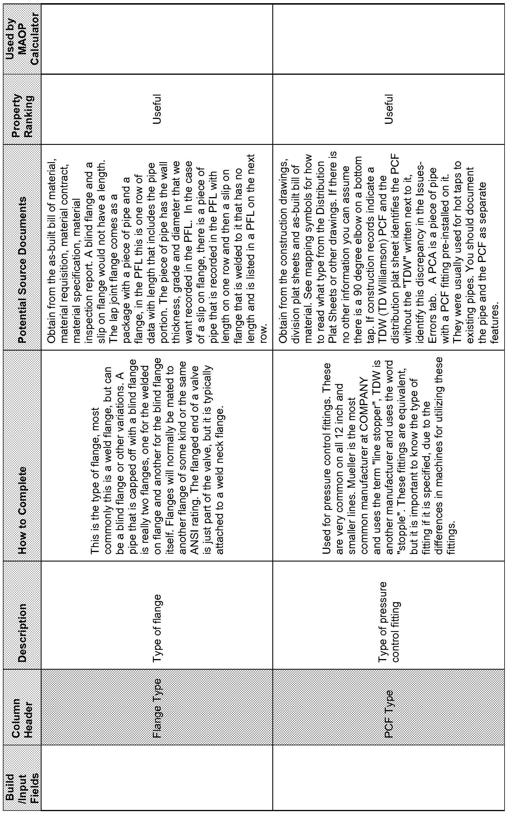


Build Used by
Co lui nn Property
/Input Description How to Complete Potential Source Documents WIAOP
He ad er Ranking
Fields Calculator
This feature can only be used when
construction drawings detailing the farm
tap are not found. You must enter the
Find the date of the installation on the
drawing number from the drop down list
service order or as-built drawings. Use
that matches the appropriate standard
the installation date of the mainline if
drawing for Farm Taps. Refer to the
the service date is not available. The
chart lower on this page that is labeled
pressure should be found using drawing
This is a farm tap as Farm Tap Regulator. Look up the
086868 or operating diagrams. If you
regulator supplying date of your installation in column D and
have more than one cut in pressure,
Farm Tap 1 or 2 adjoining the pressure along row 136. If the
enter multiple rows with the feature type Important
Regulator residential or small corresponding cell is blank use the
of Farm Tap Reg, with the appropriate
commercial closest value. The feature boundaries
Type for the individual pressure cuts. If
customers. represented by the Farm Tap regulator
construction drawings detailing the farm
vary depending on the selected
tap are found, the reg set must be built
configuration. Refer to Guideline - feature by feature, in which case
Stations and Farm Tap Regulator Sets
existing templates found in the Tools
for specific details. Long term this
directory should be utilized.
option will be eliminated as we detail all
pipe feature by feature specifically for
each installation.
Gather from the detailed construction
The Appurtenance is something attached
drawings. Revetment material (such as
Appurtenanc Type of featu to; or around the pipe, such as pipe Nice to
a pile of rocks) is used to protect slopes
e Tvpe this row. hangers, straps, pipe supports, pipe Have
and facilities from erosion by natural
anchors and related items.
forces.
Use the drop down to indicate the type of Gather from the detailed construction
Pig Type Type of trap Important
pig trap. drawings.
FVE Fields


MAOP Report Fields


[00166] It will be appreciated by those skilled in the art that while the invention has been described above in connection with particular embodiments and examples, the invention is not necessarily so limited, and that numerous other embodiments, examples, uses, modifications and departures from the embodiments, examples and uses are intended to be encompassed by the invention.
Claims
1. A pipeline analysis system comprising: a processor; a first non-transitory computer-readable storage medium for tangibly storing thereon program logic for execution by the processor, the program logic comprising: logic executed by the processor for receiving and tangibly storing on a second non-transitory computer-readable storage medium a dataset including pipeline component data corresponding to an existing or planned physical pipeline; logic executed by the processor for analyzing the dataset to determine compliance with desired maximum allowable pipeline operating pressures; logic executed by the processor for enabling revision of the pipeline component data to specify pipeline components that are in compliance with desired maximum allowable pipeline operating pressures; and logic executed by the processor for providing an exception report listing non- compliant pipeline components.
2. The pipeline analysis system of Claim 1, wherein the pipeline component data includes data corresponding to pipe segments, pipe fittings and pipe valves.
3. The pipeline analysis system of Claim 1, wherein the dataset is analyzed using batch processing techniques.
4. The pipeline analysis system of Claim 3, wherein the dataset contains pipeline component data for an entire pipeline.
The pipeline analysis system of Claim 1 , wherein the dataset is analyzed at least in part by comparing the pipeline component data to an industry standard pipeline database stored on a third non-transitory computer-readable medium.
A pipeline analysis system comprising: a processor; a first non-transitory computer-readable storage medium for tangibly storing thereon program logic for execution by the processor, the program logic comprising: logic executed by the processor for receiving and tangibly storing on a second non-transitory computer-readable storage medium a dataset including pipeline component data corresponding to an existing or planned physical pipeline; logic executed by the processor for analyzing the dataset to determine compliance with desired maximum allowable pipeline operating pressures; logic executed by the processor for enabling revision of the pipeline component data to specify at least one pipeline component having at least one different characteristic than was originally specified in the dataset; and logic executed by the processor for analyzing the revised dataset to determine the maximum allowable pipeline operating pressure for the existing or planned physical pipeline.
The pipeline analysis system of Claim 6, further including logic executed by the processor for enabling a maximum allowable pipeline operating pressure and providing an exception report listing non-compliant pipeline components.
8. The pipeline analysis system of Claim 6, wherein the pipeline component data includes data corresponding to pipe segments, pipe fittings and pipe valves.
9. The pipeline analysis system of Claim 6, wherein the dataset is analyzed using batch processing techniques.
10. The pipeline analysis system of Claim 8, wherein the dataset contains pipeline component data for an entire pipeline.
11. The pipeline analysis system of Claim 6, wherein the dataset is analyzed at least in part by comparing the pipeline component data to an industry standard pipeline database stored on a third non-transitory computer-readable medium.
Applications Claiming Priority (2)
| Application Number | Priority Date | Filing Date | Title |
|---|---|---|---|
| US201261661265P | 2012-06-18 | 2012-06-18 | |
| US61/661,265 | 2012-06-18 |
Publications (1)
| Publication Number | Publication Date |
|---|---|
| WO2013192247A1 true WO2013192247A1 (en) | 2013-12-27 |
Family
ID=49756632
Family Applications (1)
| Application Number | Title | Priority Date | Filing Date |
|---|---|---|---|
| PCT/US2013/046441 WO2013192247A1 (en) | 2012-06-18 | 2013-06-18 | System and method for calculating and reporting maximum allowable operating pressure |
Country Status (2)
| Country | Link |
|---|---|
| US (1) | US20130338833A1 (en) |
| WO (1) | WO2013192247A1 (en) |
Cited By (1)
| Publication number | Priority date | Publication date | Assignee | Title |
|---|---|---|---|---|
| US20210342507A1 (en) * | 2020-05-04 | 2021-11-04 | Schlumberger Technology Corporation | Multi-disciplinary optimization-enabled design automation and optimization for pressure-controlling components |
Families Citing this family (5)
| Publication number | Priority date | Publication date | Assignee | Title |
|---|---|---|---|---|
| US20140288908A1 (en) * | 2013-03-20 | 2014-09-25 | Infosys Limited | Methods, systems and computer-readable media for determining a time-to failure of an asset |
| US11080661B2 (en) | 2018-11-02 | 2021-08-03 | NortecView Ltd. | Automated testing of utility infrastructure assets |
| US11789651B2 (en) | 2021-05-12 | 2023-10-17 | Pure Storage, Inc. | Compliance monitoring event-based driving of an orchestrator by a storage system |
| US11816068B2 (en) | 2021-05-12 | 2023-11-14 | Pure Storage, Inc. | Compliance monitoring for datasets stored at rest |
| US11888835B2 (en) | 2021-06-01 | 2024-01-30 | Pure Storage, Inc. | Authentication of a node added to a cluster of a container system |
Citations (4)
| Publication number | Priority date | Publication date | Assignee | Title |
|---|---|---|---|---|
| US6988109B2 (en) * | 2000-12-06 | 2006-01-17 | Io Informatics, Inc. | System, method, software architecture, and business model for an intelligent object based information technology platform |
| US7370075B2 (en) * | 2002-04-25 | 2008-05-06 | Digital Evolution | Method and apparatus for managing web services within a computer network system |
| US20110145286A1 (en) * | 2009-12-15 | 2011-06-16 | Chalklabs, Llc | Distributed platform for network analysis |
| US8000936B2 (en) * | 2008-11-10 | 2011-08-16 | Saudi Arabian Oil Company | Data analysis system for determining coating conditions of a buried pipeline |
Family Cites Families (20)
| Publication number | Priority date | Publication date | Assignee | Title |
|---|---|---|---|---|
| US5983164A (en) * | 1997-02-25 | 1999-11-09 | Stella, Llc | Method and apparatus for measuring and controlling the flow of natural gas from gas wells |
| US6446014B1 (en) * | 1997-02-25 | 2002-09-03 | Cham Ocondi | Method and apparatus for measuring and controlling the flow of fluids from coal seam gas wells |
| US7096092B1 (en) * | 2000-11-03 | 2006-08-22 | Schlumberger Technology Corporation | Methods and apparatus for remote real time oil field management |
| US7676420B1 (en) * | 2002-06-19 | 2010-03-09 | Accenture Global Services Gmbh | Electronic settlement of petroleum and gas distributions |
| US7647136B2 (en) * | 2006-09-28 | 2010-01-12 | Exxonmobil Research And Engineering Company | Method and apparatus for enhancing operation of a fluid transport pipeline |
| US7653497B2 (en) * | 2007-05-15 | 2010-01-26 | Spectrasensors, Inc. | Energy flow measurement in gas pipelines |
| US7823640B2 (en) * | 2007-10-23 | 2010-11-02 | Saudi Arabian Oil Company | Wellhead flowline protection and testing system with ESP speed controller and emergency isolation valve |
| US7860669B2 (en) * | 2008-06-17 | 2010-12-28 | Saudi Arabian Oil Company | System, program product, and related methods for estimating and managing crude gravity in flowlines in real-time |
| US7859403B2 (en) * | 2008-08-06 | 2010-12-28 | Elecsys Corporation | Monitoring and alarming system and method |
| TR200805998A2 (en) * | 2008-08-12 | 2009-12-21 | Kodalfa B�Lg� Ve �Let���M Teknoloj�Ler� Sanay� Ve T�Caret A.�. | Remote wireless climate monitoring and control system for greenhouses |
| US8296100B2 (en) * | 2008-10-31 | 2012-10-23 | Chevron U.S.A. Inc. | System and method for well surveillance and management |
| US8510147B2 (en) * | 2009-12-09 | 2013-08-13 | Infosys Limited | System and method for calculating a comprehensive pipeline integrity business risk score |
| US8589088B2 (en) * | 2010-11-09 | 2013-11-19 | General Electric Company | GIS enabled pipeline upgrading system |
| US9527683B2 (en) * | 2011-07-25 | 2016-12-27 | Siemens Aktiengesellschaft | Method and device for controlling and/or regulating a fluid conveyor for conveying a fluid within a fluid line |
| US9052703B2 (en) * | 2012-02-02 | 2015-06-09 | Emerson Process Management Power & Water Solutions, Inc. | Enhanced sequential method for solving pressure/flow network parameters in a real-time distributed industrial process simulation system |
| US20140172382A1 (en) * | 2012-12-19 | 2014-06-19 | Fluor Technologies Corporation | Pipeline Network Optimization Using Risk Based Well Production |
| US8548757B1 (en) * | 2013-01-14 | 2013-10-01 | RCP Inc. | Method for calculating maximum allowable operating pressure and maximum operating pressure of a pipeline |
| US8548758B1 (en) * | 2013-01-14 | 2013-10-01 | RCP Inc. | Computer readable medium for calculating maximum allowable operating pressure and maximum operating pressure of a pipeline |
| US8548756B1 (en) * | 2013-01-14 | 2013-10-01 | RCP Inc. | System for calculating maximum allowable operating pressure and maximum operating pressure of a pipeline |
| MY180147A (en) * | 2013-03-13 | 2020-11-23 | Halliburton Energy Services Inc | Diverting flow in a drilling fluid circulation system to regulate drilling fluid pressure |
-
2013
- 2013-06-18 US US13/921,183 patent/US20130338833A1/en not_active Abandoned
- 2013-06-18 WO PCT/US2013/046441 patent/WO2013192247A1/en active Application Filing
Patent Citations (4)
| Publication number | Priority date | Publication date | Assignee | Title |
|---|---|---|---|---|
| US6988109B2 (en) * | 2000-12-06 | 2006-01-17 | Io Informatics, Inc. | System, method, software architecture, and business model for an intelligent object based information technology platform |
| US7370075B2 (en) * | 2002-04-25 | 2008-05-06 | Digital Evolution | Method and apparatus for managing web services within a computer network system |
| US8000936B2 (en) * | 2008-11-10 | 2011-08-16 | Saudi Arabian Oil Company | Data analysis system for determining coating conditions of a buried pipeline |
| US20110145286A1 (en) * | 2009-12-15 | 2011-06-16 | Chalklabs, Llc | Distributed platform for network analysis |
Cited By (1)
| Publication number | Priority date | Publication date | Assignee | Title |
|---|---|---|---|---|
| US20210342507A1 (en) * | 2020-05-04 | 2021-11-04 | Schlumberger Technology Corporation | Multi-disciplinary optimization-enabled design automation and optimization for pressure-controlling components |
Also Published As
| Publication number | Publication date |
|---|---|
| US20130338833A1 (en) | 2013-12-19 |
Similar Documents
| Publication | Publication Date | Title |
|---|---|---|
| WO2013192247A1 (en) | System and method for calculating and reporting maximum allowable operating pressure | |
| KR102056320B1 (en) | Smart Plant Multidimensional Space 3D Piping Design Collaboration System | |
| Lecchi | Evaluation of predictive assessment reliability on corroded transmission pipelines | |
| KR20000011770A (en) | Apparatus for and method of designing fluid control devices | |
| US8855972B2 (en) | Manufacture of heat trace cable, design, installation, and management, and method thereof | |
| JP2008281355A (en) | Corrosion risk evaluation method, maintenance plan creation method, corrosion risk evaluation program, maintenance plan creation program, corrosion risk evaluation device, and maintenance plan creation device | |
| JP5022857B2 (en) | Pipeline information system | |
| Leis | Evolution of metal-loss severity criteria: gaps and a path forward | |
| Zhou et al. | Research and application of natural gas pipeline assessment method in Location Class upgrading areas | |
| Park et al. | Quantitative and Probabilistic Approach for Underground Pipeline Management Optimization | |
| Ellingsen et al. | First Set of Bulk Standard Specifications Set to Reduce Cost and Delays in Offshore Oil & Gas Projects | |
| Smith et al. | The Why and How of Data Integration for Integrity Management Pursuant to API TR 1178 | |
| Maksimov et al. | Comprehensive evaluation of costs at the early stages of project development: Costs of equipment not included in the construction estimate | |
| Torres et al. | Automatic Verification of Instrumentation Lessons Learned in New FPSO Projects by Using Constructability-Based Queries Applied to CAE Computer Aided Engineering Tools Databases | |
| Vinnem et al. | Use of Risk Analysis During the Operations Phase | |
| Saaud et al. | Offshore Facilities Load Out-Case Study of Jacket Superstructure Loadout by Strand Jacking Skidding Method | |
| Van Zyl | Development of a two-tier prioritisationalgorithm for the replacement of water reticulation pipes | |
| Yan | Experimental and numerical evaluation of a new composite pressure pipe for a Trenchless Rehabilitation Technology | |
| WO2020149074A1 (en) | Plant maintenance supporting apparatus | |
| Dehran et al. | Piping & Instrumentation Interface Optimization | |
| Sharma | Certificate | |
| Kosmalski et al. | Risk Factors in a Process of Gas Supply Pipeline Construcion | |
| Guillen et al. | An integrity programme to restore the MAOP of a high pressure gas pipeline in Venezuela | |
| Shih et al. | Life cycle guideline of petrochemical plant underground piping system | |
| McDonnell et al. | Pipeline ALIAS: A Universal Nomenclature System for the Pipeline Industry |
Legal Events
| Date | Code | Title | Description |
|---|---|---|---|
| 121 | Ep: the epo has been informed by wipo that ep was designated in this application |
Ref document number: 13806596 Country of ref document: EP Kind code of ref document: A1 |
|
| NENP | Non-entry into the national phase |
Ref country code: DE |
|
| 122 | Ep: pct application non-entry in european phase |
Ref document number: 13806596 Country of ref document: EP Kind code of ref document: A1 |