The nickname for the JPole antenna (J-Pole) is due to its’ 2 parallel elements forming the shape of a ‘J’. There are two versions of antenna; The 60-foot Sr version covers 10-160 meters and the 34-foot Jr version covers 6-80 meters. Whether you are using the Sr or the Jr version, you may use a tuner to achieve a near perfect SWR on these bands.
For efficiency, see the section below titled “Radiation (Signal) Patterns”.
Placement of the J-Pole (JPole) antenna for DX
For optimum DX deploy the antenna with the feed point at 30 feet or higher and slope it down to 10 feet or higher. Install the antenna with the feed-point at the lower position to increase NVIS.
Placement of the JPole antenna (J-Pole) for NVIS
Deploy the antenna horizontally at a height of 1/8 wavelength to optimize NVIS (Near Vertical Incident Skywave) performance in the 0–650 km (0–400 miles) range.
What not to do
We do not recommend installing this antenna as a Vertical in high noise environments. As verticals are inherently prone to high noise (RFI).
Installation Tips
Here are a few tips that have proven to help other operators during and after deployment of the JPole antenna (J-Pole):
- Install an RF Choke for common mode current if you hear feedback through speakers, etc. when you transmit.
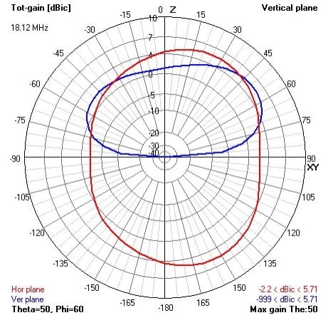
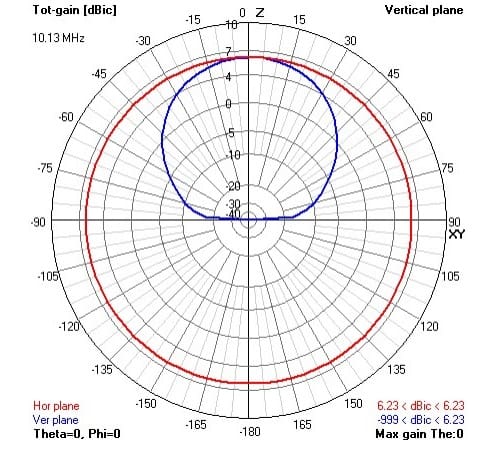
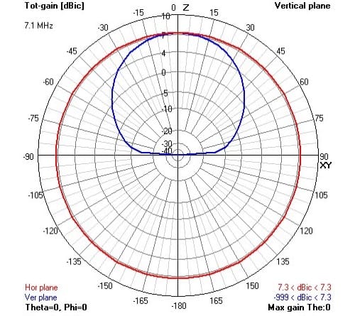
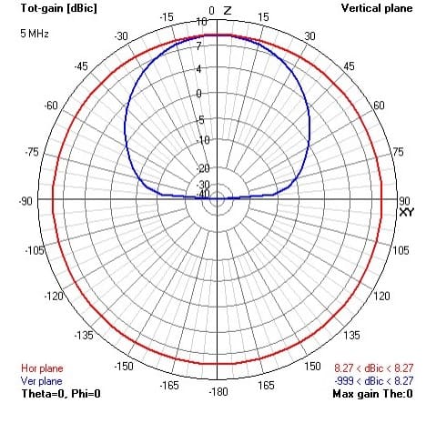
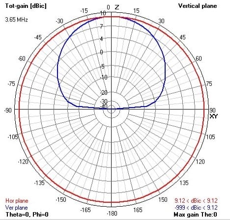
Radiation (Signal) Patterns
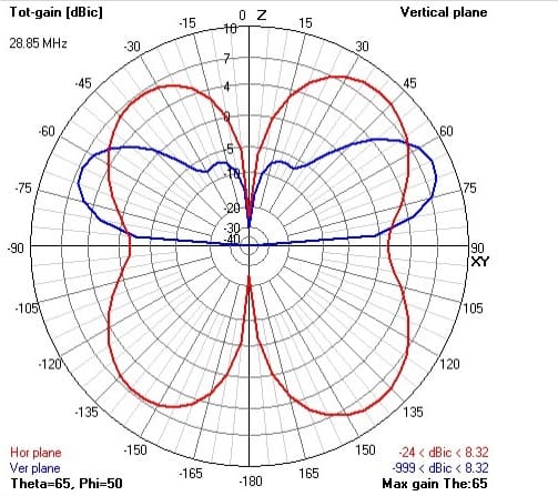
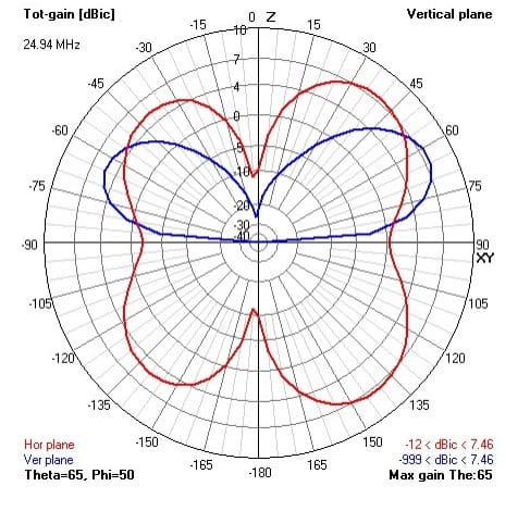
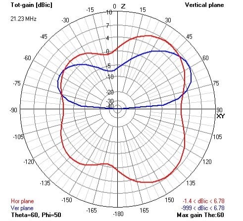
A benefit of using the HF JPole antenna (J-Pole) on lower bands are the bulbous radiation patterns. These patterns have a more omnidirectional pattern when it is placed in free space. These charts are the gain figures for the Jr version. Simply add approximately 40% more gain for the Sr version.

SWR Analysis of the Jr and Sr J-Pole Antennas


-
 10-160M 60ft end fed HF Sr$219.00
 -
6-80M 34ft end fed HF Jr$199.00
- Install an RF Choke for common mode current if you hear feedback through speakers, etc. when you transmit.
Radiation (Signal) Patterns
A benefit of using the HF JPole antenna (J-Pole) on lower bands are the bulbous radiation patterns. These patterns have a more omnidirectional pattern when it is placed in free space. These charts are the gain figures for the Jr version. Simply add approximately 40% more gain for the Sr version.
SWR Analysis of the Jr and Sr J-Pole Antennas
- We do not recommend installing this HF antenna as a Vertical. Verticals are inherently prone to high noise (RFI) and unpredictable radiation patterns due to proximity of coax.
- The curve after deployment of the wire once deployed should be done so the element does not ‘see’ itself. This is accomplished by ensuring that the angle of the wire is greater than 140 degrees.
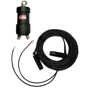
- Ground your equipment using the ground bolt on the back of each component.
- Do not install a BaLun or Air Choke for the initial installation at the antenna.
- Install an RF Choke for common mode current if you hear feedback through speakers, etc. when you transmit.
Radiation (Signal) Patterns
A benefit of using the HF JPole antenna (J-Pole) on lower bands are the bulbous radiation patterns. These patterns have a more omnidirectional pattern when it is placed in free space. These charts are the gain figures for the Jr version. Simply add approximately 40% more gain for the Sr version.
SWR Analysis of the Jr and Sr J-Pole Antennas