
Related Manuals for Gigabyte GA-945GCMX-S2


Summary of Contents for Gigabyte GA-945GCMX-S2
- Page 1 GIGABYTE Motherboards Supports lntel®Core™2 Duo Processors GA-94SGCM(X)-SS User's Manual S Features Smart Safe...
- Page 2 GA-945GCM-S2 GA-945GCMX-S2 Intel® Core™ 2 Extreme dual-core I Core™ 2 Duo I Intel® Pentium® D / Pentium® 41 Celeron® D LGA775 Processor Motherboard User's Manual Rev. 6602 12ME-945CMX2R-6602R * The WEEE marking on the product indicates this product must not be disposed of with user's other household waste and must be handed over to a designated collection point for the recycling of waste electrical and electronic equipment!! * The WEEE marking applies only in European Union's member states.
- Page 3 Ausschlager Weg 41,1F 20537 Hamburg, Germany declare thai (he product (descriplion of ihe apparatus, system, installation lo which it refers) Motherboard GA-945GCMX-S2 is in confomiity with (reference to the specification under which conformity is declared) in accordance with 89/336 EEC-EMC Directive...
- Page 4 DECLARATION OF CONFORMITY Per FCC Part 2 Section 2.1077(a) Responsible Party Name:G.B.T. INC. (U.S.A.) Address: 17358 Railroad Street City of Industry, CA 91748 Phone/Fax No: (818) 854-9338/ (818) 854-9339 hereby declares that the product Product Name: M o t h e r b o a r d Model Number: G A - 9 4 5 G C M X - S 2 Conforms to the following specifications: FCC Part 15, Subpart B, Section 15.107(a) and Section 15.109...
- Page 5 Declaration of Conformity We, Manufacturer/Importer (fun address) G.B.T, Technology Trading GMbH Ausschlager Wog 41,1F 20537 Hamburg, Germany declare thai the product (description of the apparatus, system, installation to which it refers) Motherboard GA-945GCM-S2 is in conformity with (reference to (he specification under which conformity is declared) in accordance with 89/336 EEC-EMC Directive Limits and methods of measurement 3 EN 61000-3-2...
- Page 6 DECLARATION OF CONFORMITY Per FCC Part 2 Section 2.1077(a) Responsible P a r t y Name:G.B.T. INC. (U.S.A.) Address: 17358 Railroad Street City of Industry, CA 91748 Phone/Fax No: (818) 854-9338/ (818) 854-9339 hereby declares that the product Product Name: M o t h e r b o a r d Model Number: G A - 9 4 5 G C M - S 2 Conforms to the following specifications: FCC Part 15, Subpart B, Section 15.107(a) and Section 15.109...
- Page 7 Gigabyte's prior written permission. Specifications and features are subject to change without prior notice. Product Manual Classification In order to assist in the use of this product, Gigabyte has categorized the user manual in the following: •...
-
Page 8: Table Of Contents
Installation of Expansion Cards I/O Back Panel Introduction Connectors Introduction Chapter 2 BIOS Setup T h e Main Menu (For example: GA-945GCMX-S2 BIOS V e r . : F5a) Standard C M O S Features Advanced BIOS Features Integrated Peripherals... - Page 9 Chapter 3 Install Drivers Install Chipset Drivers Software Applications Driver CD Information Hardware information Contact Us Chapter 4 Appendix Unique Software Utilities 4 - 1 - 1 E a s y T u n e 5 I n t r o d u c t i o n 4 - 1 - 2 X p r e s s R e c o v e r y 2 I n t r o d u c t i o n 4 - 1 - 3...
-
Page 10: Item Checklist
Item Checklist IDE Cable x 1 and FDD Cable x 1 SATA 3Gb/s Cable x 2 I/O Shield * The items listed above are for reference only, and are subject to change without notice. Optional Accessories • 2 Ports USB 2.0 Cable (Part Number: 12CR1-1UB030-51/R) •... -
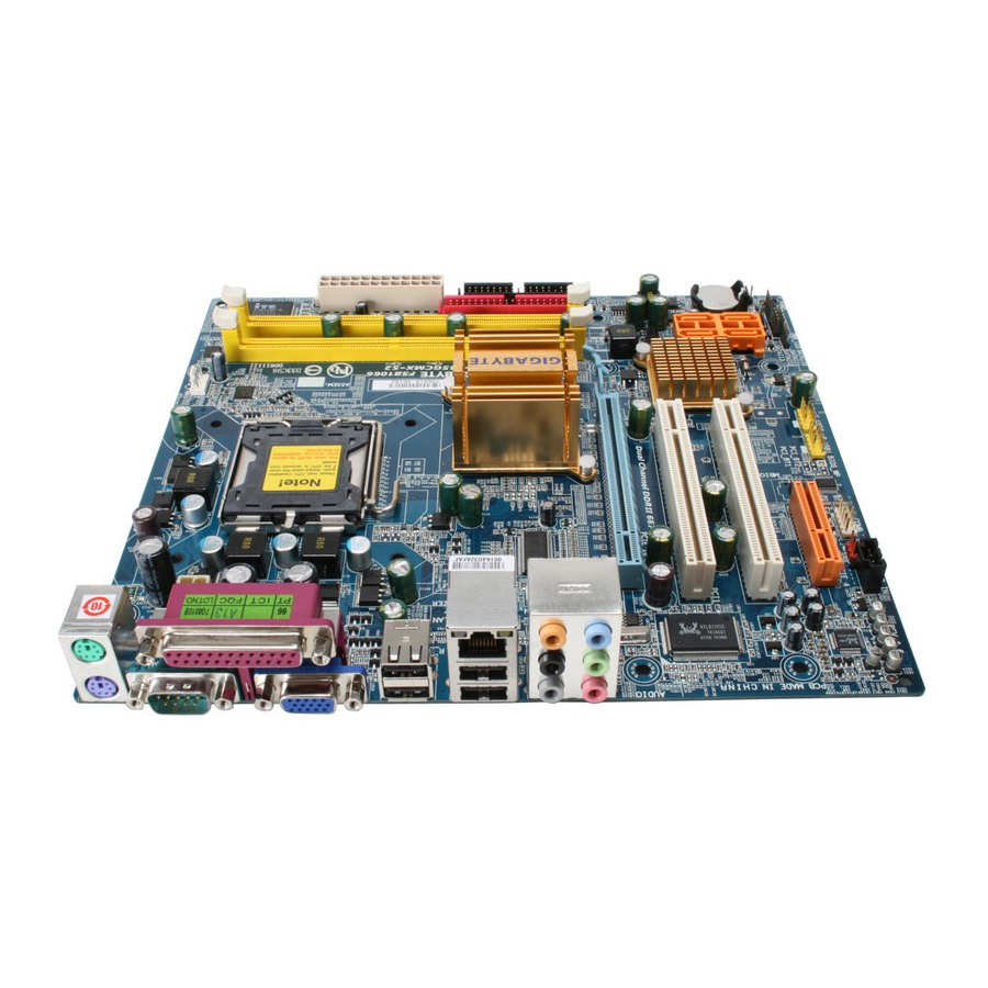
Page 11: Ga-945Gcmx-S2 Motherboard Layout
GA-945GCMX-S2 Motherboard Layout CPU_FAN р г т д PCIE_4 BATTERY С iniiiiiini iiifjmiiRriniiin Д г ' т 1,.11итт*ттпппттитптттпгч • л CLR_CM0S<33 F_usBiEnmnO ШШШ CODEC r ^ l H p i И11Ш1 о з з Е ш а з ш ш... -
Page 12: Ga-945Gcm-S2 Motherboard Layout
GA-945GCIVI-S2 Motherboard Layout S P D 1 F J O... -
Page 13: Block Diagram
FSB 1333 MHz Core™ 2 CPU with DDR2 533 (or above) memory module(s). (Note 2) Use of a 1066/800 MHz FSB CPU is required if you wish to install DDR2 667 MHz memory. ® Only for GA-945GCMX-S2, © Only for GA-945GCM-S2. -
Page 14: Chapter 1 Hardware Installation
Damage as a result of violating the conditions recommended in the user manual. Damage due to improper installation. Damage due to use of uncertified components. Damage due to use exceeding the permitted parameters. Product determined to be an unofficial Gigabyte product. - 11 - "Hardware Installation... -
Page 15: Feature Summary
1 CD In connector 1 S/PDIF in/Out connector 2 USB 2.0/1.1 connectors for additional 4 ports by cables 1 COMB connector 1 Chassis Intrusion connector 1 power LED connector © Only for GA-945GCMX-S2. © Only for GA-945GCM-S2. GA-945GCM(X)-S2 Motherboard - 12 -... - Page 16 Rear Panel I/O 1 PS/2 keyboard port 1 PS/2 mouse port 1 parallel port 1 serial port 1 D-Sub port 4 USB 2.0/1.1 ports 1 RJ-45 port 6 audio jacks (Line In / Line Out / MIC In/Surround Speaker Out (Rear Speaker Out)/Center/Subwoofer Speaker Out/Side Speaker Out) I/O Control IT8718 chip...
-
Page 17: Installation Of The Cpu And Cpu Cooler
Installation of the CPU and CPU Cooler Before installing the CPU, please comply with the following conditions: Please make sure that the motherboard supports the CPU. Please take note of the one indented corner of the CPU. If you install the CPU in the wrong direction, the CPU will not insert properly. -
Page 18: I N S T A L L A T I O N Of T H E C P U C O O L E
1-3-2 Installation of the CPU Cooler Push Pin top of Female Push Pin Female Push Pin Fig.1 Fig. 2 Please apply an even layer of CPU cooler paste (Turning the push pin along the direction of arrow is to on the surface of the installed CPU. remove the CPU cooler, on the contrary, is to install.) Please note the direction of arrow sign on the male push pin doesn't face inwards before installation. -
Page 19: Installation Of Memory
Installation of Memory Before installing the memory modules, please comply with the following conditions: Please make sure that the memory used is supported by the motherboard. It is recommended that memory of similar capacity, specifications and brand be used. Before installing or removing memory modules, please make sure that the computer power is switched off to prevent hardware damage. - Page 20 Technology. After operating the Dual Channel Technology, the bandwidth of memory bus will double. The GA-945GCMX-S2/GA-945GCM-S2 includes 2 DIMM sockets. If you want to operate the Dual Channel Technology, please note the following explanations due to the limitation of Intel chipset specifications.
-
Page 21: Installation Of Expansion Cards
Installation of Expansion Cards To install your expansion card, follow the steps below. Disconnect your system from its power source and read the expansion card's installation manual before installing the expansion card in the computer. Remove your computer's chassis cover, screws and slot bracket from the computer. Ground yourself to prevent damage to your computer resulting from Electrostatic discharge (ESD). -
Page 22: I/O Back Panel Introduction
I/O Back Panel Introduction @ © ® o © • © о ( о ) в ( о ) « > PS/2 Keyboard and PS/2 Mouse Connector To install a PS/2 port keyboard and mouse, plug the mouse to the upper port (green) and the keyboard to the lower port (purple). -
Page 23: Connectors Introduction
MIC In The default MIC In jack. Microphone must be connected to MIC In jack. ^ ч ^ In addition to the default speakers settings, t h e @ ~ 0 audio jacks can be reconfigured to perform different functions via the audio software. Only microphones still MUST be connected to the default Mic In jack ( ®... - Page 24 1/2) A T X J 2 V I ATX (Power Connector) With the use of the power connector, the power supply can supply enough stable power to all the components on the motherboard. Before connecting the power connector, please make sure that all components and devices are properly installed.
- Page 25 3/4) CPU_FAN / SYS_FAN (Cooler Fan Power Connector) The cooler fan power connector supplies a +12V power voltage via a 3-pin/4-pin(CPU_FAN) power connector and possesses a foolproof connection design. Most coolers are designed with color-coded power connector wires. A red power connector wire indicates a positive connection and requires a +12V power voltage.
- Page 26 6) IDE (IDE Connector) An IDE device connects to the computer via an IDE connector. One IDE connector can connect to one IDE cable, and the single IDE cable can then connect to two IDE devices (hard drive or optical drive). It you wish to connect two IDE devices, please set the jumper on one IDE device as Master and the other as Slave (for information on settings, please refer to the instructions located on the IDE device).
- Page 27 PWR_LED T h e P W R _ L E D c o n n e c t o r is c o n n e c t e d w i t h the s y s t e m p o w e r indicator to indicate w h e t h e r the s y s t e m is on/off.
- Page 28 10) F_PANEL (Front Panel Jumper) Please c o n n e c t the p o w e r LED, PC s p e a k e r , reset s w i t c h and p o w e r s w i t c h etc. of your chassis front panel to the F _ P A N E L c o n n e c t o r according to the pin a s s i g n m e n t below.
- Page 29 11) F_AUDIO (Front Audio Connector) This connector supports either HD (High Definition) or AC'97 front panel audio module. If you wish to use the front audio function, connect the front panel audio module to this connector. Check the pin assignments carefully while you connect the front panel audio module. Incorrect connection between the module and connector will make the audio device unable to work or even damage it.
- Page 30 13) SPDIFJO (S/PDIF In/Out Connector) The S/PDIF output is capable of providing digital audio to external speakers or compressed AC3 data to an external Dolby Digital Decoder. Use this feature only when your stereo system has digital input function. Use S/PDIF IN feature only when your device has digital output function. Be careful with the polarity of the S P D I F J O connector.
- Page 31 15) COMB (COMB Connector) Be careful with the polarity of the COMB connector. Check the pin assignments while you connect the COMB cable. Please contact your nearest dealer for optional COMB cable. Pin No. Definition NDCDB- щ NSINB NSOUTB NDTRB- NDSRB- NRTSB- NCTSB-...
- Page 32 17) Cl ( C h a s s i s I n t r u s i o n , C a s e O p e n ) This 2-pin connector allows your system to detect if the chassis cover is removed. You can check the "Case Opened"...
-
Page 33: Chapter 2 Bios Setup
CMOS SETUP screen. You can enter the BIOS setup screen by pressing "Ctrl + F1". If you wish to upgrade to a new BIOS, either GIGABYTE'S Q-Flash or @BIOS utility can be used. Q-Flash allows the user to quickly and easily update or backup BIOS without entering the operating s y s t e m . -
Page 34: The Main Menu (For Example: Ga-945Gcmx-S2 Bios Ver.: F5A)
USB-HDD •t4.:Move Enter :Accept ESC:Exit The Main Menu (For example: GA-945GCMX-S2 BIOS Ver.: F5a) Once you enter Award BIOS CMOS Setup Utility, the Main Menu (as figure below) will appear on the screen. Use arrow keys to select among the items and press <Enter> to accept or enter the sub-menu. - Page 35 н S t a n d a r d C M O S F e a t u r e s This setup page includes all the items in standard compatible BIOS. В A d v a n c e d B I O S F e a t u r e s This setup page includes all the items of Award special enhanced features.
-
Page 36: Standard Cmos Features
Standard CMOS Features C M O S S e t u p U t i l i t y - C o p y r i g h t (C) 1984-2007 Award S o f t w a r e Standard C M O S Features Г... - Page 37 • • Access Mode Use this to set the access mode for the hard drive. The two options are: Large/Auto(default:Auto) >• Capacity Capacity of currently installed hard drive. Hard drive information should be labeled on the outside drive casing. Enter the appropriate option based on this information.
-
Page 38: Advanced Bios Features
The system will boot, but access to Setup will be denied if the correct password is not entered at the prompt. (Default value) (Note) This item will show up when you install a processor which supports this function. © Only for GA-945GCMX-S2. GA-945GCM(X)-S2 Motherboard - 36 -... - Page 39 Virtualization Technology (No,e| •• Enabled Enable Virtualization technology function. (Default value) >• Disabled Disable this function. (Note) This item will show up when you install a processor which supports this function. ® Only for GA-945GCMX-S2. - 37 - BiOS Setup...
-
Page 40: Integrated Peripherals
Integrated Peripherals C M O S Setup U t i l i t y - C o p y r i g h t (C) 1984-2007 Award S o f t w a r e I n t e g r a t e d P e r i p h e r a l s O n - Q h i p P r i m a r y PCI I D E [ E n a b l e d ] Iteir... - Page 41 O- USB 2.0 Controller You can disable this function if you are not using onboard USB 2.0 feature. • • Enabled Enable USB 2.0 controller. (Default value) • • Disabled Disable USB 2.0 controller, o- USB Keyboard Support •• Enabled Enable USB keyboard support.
- Page 42 о- SMART LAN (LAN Cable Diagnostic Function) C M O S Setup Utility-Copyright (C) 1984-2007 Award Software S M A R T LAN toff Rair.1 Status = Open / Length O.Om Menu Level* Pat_r3j;6 Status Open / Length O.Om Pair4-5 Status - Open •...
- Page 43 О- Onboard LAN Boot ROM This function decide whether to invoke the boot ROM of the onboard LAN chip. • • Enabled Enable this function. • • Disabled Disable this function. (Default value) Onboard Serial Port 1 • • Auto BIOS will automatically setup the port 1 address.
-
Page 44: Power Management Setup
Power Management Setup C M O S Setup U t i l i t y - C o p y r i g h t (C) 1984-2007 Award S o f t w a r e P o w e r M a n a g e m e n t S e t u p A C P I S u s p e n d Type t S l ( P O S ) ] I t e m H e l p... - Page 45 о- Power On By Keyboard •• Disabled Disable this function. (Default value) • • Password Enter from 1 to 5 characters to set the keyboard power on password. •• Keyboard 98 If your keyboard have "POWER Key" button, you can press the key to power on the system.
-
Page 46: Pnp/Pci Configurations
PnP/PCI Configurations C M O S Setup U t i l i t y - C o p y r i g h t (C) 1984-2007 Award S o f t w a r e P n P / P C I C o n f i g u r a t i o n s PCI 1 IRQ A s s i g n m e n t Item H e l p PCI 2 I R Q A s s i g n m e n t... -
Page 47: Pc Health Status
PC Health Status C M O S S e t u p Utility-Copyright (C) 1 9 S 4 - 2 0 0 7 Award S o f t w a r e P C Health Status [ D i s a b l e d ] Reset C a s e O p e n Status Menu Level* C u r r e n t C P U Т... - Page 48 CPU Smart FAN Control •• Disabled Disable this function. •• Enabled When this function is enabled, CPU fan will run at different speed depending on CPU temperature. Users can adjust the fan speed with Easy Tune based on their requirements. (Default value) o - CPU Smart FAN Mode This option is available only when CPU Smart FAN Control is enabled.
-
Page 49: Frequency/Voltage Control
If you use a 1333 MHz FSB processor, set "CPU Host Frequency" to 333 MHz. Incorrect using it may cause your system broken. For power End-User use only! (Note) This item will show up when you install a processor which supports this function. © Only for GA-945GCMX-S2. - 47 - BiOS Setup... - Page 50 Please note that by overclocking your system through the increase of the CPU voltage, damage to the CPU or decrease in the CPU life expectancy may occur, o- Normal CPU Vcore ® Display your CPU vcore voltage. ® Only for GA-945GCMX-S2. GA-945GCM(X)-S2 Motherboard ^ 4 8 ^...
-
Page 51: Load Fail-Safe Defaults
Load Fail-Safe Defaults C M O S Setup Utility-Copyright (C') 1984-2007 Award S o f t w a r e Fail-Safe defaults contain the most appropriate values of the system parameters that allow minimum system performance. Load Optimized Defaults C M O S Setup Utility-Copyright (C) 1984-2007 Award S o f t w a r e Standard C M O S F e a t u r e s Load F a i l - S a f e D e f a u l t s Load O p t i m i z e d D e f a u l t s... -
Page 52: 2-10 Set Supervisor/User Password
2-10 Set Supervisor/User Password C M O S S e t u p Utility-Copyright (C') 1984-2007 Award S o f t w a r e • Standard C M O S Features L o a d F a i l - S a f e D e f a u l t s ? ' . •... -
Page 53: 2-11 Save & Exit Setup
2-11 Save & Exit Setup C M O S Setup Utility-Copyright (C) 1 9 8 4 - 2 0 0 7 Award S o f t w a r e S t a n d a r d C M O S F e a t u r e s L o a d F a i l - S a f e D e f a u l t s A d v a n c e d B I O S F e a t u r e s L o a d O p t i m i z e d D e f a u l t s... -
Page 54: Chapter 3 Install Drivers
Chapter 3 Install Drivers Pictures below are shown in Windows XP. Insert the driver CD-title that came with your motherboard into your CD-ROM drive, the driver CD-title will auto start and show the installation guide. If not, please double click the CD-ROM device icon in "My computer", and execute the Run.exe. -
Page 55: Software Applications
Software Applications This page displays all the tools that Gigabyte developed and some free software, you can choose anyone you want and press "install" to install them. | A i a * a d •, v . . awn mart 1.». Ш all»»«>•< am Ьапйшо inftmwrfo* su.h м W J лЛ memoi. and gr<t>i . -
Page 56: Hardware Information
Contact Us Please see the last page for details. [ B 975/955/5451.14 07jdi05.1. Г | GIGABYTE" I n t e l * 9 7 5 / 9 5 5 / 9 4 5 Chipset Family UtUftiesCD GIGABYTE Cnipses Driver- . -
Page 57: Chapter 4 Appendix
Display screen Display panel of CPU frequency Function display LEDs Shows the current functions status GIGABYTE Logo Log on to GIGABYTE website Help button Display EasyTune™ 5 Help file Exit or Minimize button Quit or Minimize EasyTune™ 5 software (Note) EasyTune 5 functions may vary depending on different motherboards. - Page 58 4-1-2 Xpress Recovery2 Introduction Xpress Recovery2 is designed to provide quick backup and restora- tion of hard disk data. Supporting Microsoft operating systems including Windows XP/2000/NT/98/Me and DOS, and file systems including FAT16, FAT32, and NTFS, Xpress Recovery2 is able to back up data on hard disks on PATA and SATA IDE controllers.
- Page 59 The Main Screen of Xpress Recovery2 1. RESTORE: Restore the backed-up data to your hard disk. (This button will not appear if there is no backup file.) 2. BACKUP: Back up data from hard disk. 3. REMOVE: Remove previously-created backup files to release disk space.
-
Page 60: F L A S H B I O S M E T H O D I N T R O D U C T I O
Before Use: Follow the steps below before using Q-Flash to update BIOS: From GIGABYTE'S website, download the latest compressed BIOS update file that matches your motherboard model. Extract the downloaded BIOS files and save the new BIOS file (e.g. 9gcmxs2.F1) to your floppy diskor hard disk. - Page 61 с. Select the BIOS file and press ENTER. Make sure again the BIOS file matches your motherboard model. Step 2: The process of system reading the BIOS file from the floppy disk is displayed on the screen. When the message "Are you sure to update BIOS?" appears, press ENTER. The BIOS update will begin and the current process will be displayed.
- Page 62 ! 3. The @B!OS Utility Please select ©BIOS server site: • . . - • • . Gigabyte ©BIOS server 2 in Tat :an Gigabyte ©BIOS ser\ -л in China Gigabyte ©BIOS server in Japan Cancel Gigabyte ©BIOS server in U.\ A 1.
- Page 63 In method I, if the BIOS file you need cannot be found in @BIOS™ server, please go onto Gigabyte's web site for downloading and updating it according to method II. IV. Please note that any interruption during updating will cause system unbooted.
-
Page 64: Channel Audio Function Introduction -
4-1-4 2-14-16-18- Channel Audio Function Introduction The default speaker settings for the 6 audio jacks are as shown in the picture to the right. The jack retasking capability supported by HD Audio allows users to change the function for each audio jack by the audio software provided. - Page 65 STEP 3: Connect a speaker or headphone to the rear Line Out jack, a smali window will pop up and ask y o u w h a t t y p e of e q u i p m e n t is c o n n e c t e d . Choose Headphone or Line Out depending on the device connected and click OK.
- Page 66 STEP 3: Connect the 4-channel speakers to the audio jacks on the motherboard and the surround cable, a small window will pop up and ask you what type of equipment is connected. Choose a device de- pending on the type of speaker connected (4- channel audio consists of Front Speaker Out (Line Out) and Rear Speaker Out) and then click OK.
- Page 67 STEP 2: In the Audio Control Panel, click the Audio I/O tab. In the upper left list, click 6CH Speaker. STEP 3: Connect the 6-channel speakers to the audio jacks on the motherboard and the surround cable, a small window will pop up and ask you what type of equipment is connected.
- Page 68 STEP 3: Connect the 8-channel speakers to the audio jacks on the motherboard and the surround cable, a small window will pop up and ask you what type of equipment is connected. Choose a device de- pending on the type of speaker connected (8- channel audio consists of Front Speaker Out (Line Out), Rear S p e a k e r Out, C e n t e r / S u b w o o f e r Speaker Out, and Side Speaker Out) then click...
-
Page 69: Troubleshooting
Below is a collection of general asked questions. To check general asked questions based on a specific motherboard model, please log on to http://www.gigabyte.com.tw Question 1:1 cannot see some options that were included in previous BIOS after updating BIOS. Why? Answer: Some advanced options are hidden in new BIOS version. - Page 70 WEB address: http://www.gigabyte.cn Taipei 231, Taiwan Shanghai TEL:+886-2-8912-4888 TEL:+86-21-63410999 FAX:+886-2-89124003 FAX:+86-21-63410100 Tech. and Non-Tech. Support (Sales/Marketing): Beijing http://ggts.gigabyte.com.tw TEL:+86-10-62102838 WEB address (English): http://www.gigabyte.com.tw FAX:+86-10-62102848 Wuhan WEB address (Chinese): http://www.gigabyte.tw » U . S A TEL:+86-27-87851061 G.B.T. INC. FAX:+86-27-87851330 TEL:+1-626-854-9338 GuangZhou...
- Page 71 WEB address: http://www.gigabyte.co.yu О Czech Republic Representative Office Of GIGA-BYTE Technology Co., Ltd. You may go to the GIGABYTE website, select your language in CZECH REPUBLIC in the language list on the top right corner of the website. WEB address: http://www.gigabyte.cz о...